EP2154297A2 - Brauseanordnung - Google Patents
Brauseanordnung Download PDFInfo
- Publication number
- EP2154297A2 EP2154297A2 EP09167263A EP09167263A EP2154297A2 EP 2154297 A2 EP2154297 A2 EP 2154297A2 EP 09167263 A EP09167263 A EP 09167263A EP 09167263 A EP09167263 A EP 09167263A EP 2154297 A2 EP2154297 A2 EP 2154297A2
- Authority
- EP
- European Patent Office
- Prior art keywords
- shower
- wall
- fitting
- connection
- flush
- Prior art date
- Legal status (The legal status is an assumption and is not a legal conclusion. Google has not performed a legal analysis and makes no representation as to the accuracy of the status listed.)
- Granted
Links
Images

Classifications
-
- E—FIXED CONSTRUCTIONS
- E03—WATER SUPPLY; SEWERAGE
- E03C—DOMESTIC PLUMBING INSTALLATIONS FOR FRESH WATER OR WASTE WATER; SINKS
- E03C1/00—Domestic plumbing installations for fresh water or waste water; Sinks
- E03C1/02—Plumbing installations for fresh water
- E03C1/04—Water-basin installations specially adapted to wash-basins or baths
- E03C1/0408—Water installations especially for showers
-
- E—FIXED CONSTRUCTIONS
- E03—WATER SUPPLY; SEWERAGE
- E03C—DOMESTIC PLUMBING INSTALLATIONS FOR FRESH WATER OR WASTE WATER; SINKS
- E03C1/00—Domestic plumbing installations for fresh water or waste water; Sinks
- E03C1/02—Plumbing installations for fresh water
- E03C1/06—Devices for suspending or supporting the supply pipe or supply hose of a shower-bath
Definitions
- the invention relates to a shower assembly with a concealed fitting and to be controlled by means of the flush-mounted shower.
- a shower assembly should be installed without having to make too much structural changes.
- the space for a concealed fitting may be present or can be created.
- a concealed fitting is already present, which may need to be replaced only.
- the invention is based on the object to provide a certain particular for retrofitting shower arrangement, which is provided with a concealed fitting.
- the invention proposes a shower arrangement with the features mentioned in claim 1. Further developments of the invention are the subject of dependent claims.
- the wall bar itself which can be designed as a standard wall bar, serves at the same time the water supply to the overhead shower and to the representation of a conventional wall bar, with the possibility to place there objects that should be adjustable in height. These include, for example, mirrors, holders for shower additives or the like.
- the wall bar can also serve to form the holder of the overhead shower, so not only a way to attach an overhead shower to her, but form the overhead shower as a conclusion and final element of the wall bar.
- it may be provided, of course, to bend or bend the wall bar in its end region into the room or to arrange the overhead shower with a horizontal distance from the wall.
- the wall bar of her Starting from the connection with the concealed fitting is formed straight-line, so that their connection with the flush-mounted fitting is arranged outside the wall.
- the wall bar practically grows out of the concealed fitting upwards.
- the wall bar can be designed such that it rests directly on the wall surface. It can also be attached to this wall surface. According to the invention may also be provided in a further development that the wall bar is arranged at a distance from the wall, in particular with such a distance, which not only allows easy cleaning behind the wall bar, but also the attachment of holders, which rotates around the wall bar can be. This should allow objects to be turned to the side. For connection to the wall, a fastening element can then be provided in the upper area.
- an adapter element For hydraulic connection between the not specifically adapted to the wall rod flush-mounted fitting and the wall rod, an adapter element is provided which produces this connection. It can be provided in particular that the adapter element is at least partially contained in a covering rosette of the flush-mounted fitting. This cover rosette can be designed so that it visually enters into a connection with the wall rod, in particular adapted to this.
- the adapter element can thereby pass through the covering rosette.
- the shower arrangement has a device for angular alignment of the wall bar with respect to the flush-mounted fitting. Since the wall bar has a considerable length up to the overhead shower, However, an angular error in the alignment of the rosette, which is not detectable on the back with the naked eye, on the wall rod but still be determined. To avoid such and beauty is proposed by the invention of this alignment.
- the adapter element which produces the hydraulic connection, be designed so that this orientation is still allowed.
- a line piece between the outlet of the sanitary fitting and the wall bar can be arranged in the adapter element or in the rosette, which allows a length compensation and / or an angle compensation.
- length compensation two pipe parts can be inserted telescopically into one another.
- angle compensation a line end can be inserted into a bore, which can be rotated relative to it.
- a deformable line piece such as a hose.
- a shower arrangement which is particularly suitable for retrofitting or cultivation, may be provided in a development that the shower assembly also has a connection for a shower hose. This is especially true because you can then attach a holder for a hand shower on the anyway existing wall bar.
- connection for a shower hose outside the flush-mounted fitting receiving wall is arranged and in particular also runs parallel to the wall surface.
- the connection for the shower hose points in a direction opposite the wall bar.
- connection for the shower hose is arranged in a straight line extension of the wall rod.
- the wall bar and / or the connection for the shower hose is arranged laterally on the flush-mounted fitting.
- an adapter element is present between the connection for the shower hose and the sanitary fitting, which is also expediently arranged in the rosette and passes through it.
- the adapter element between the sanitary fitting and the wall rod or between the sanitary fitting and the connection for the shower hose form such that the wall bar and / or the connection for the shower hose either right or left side of the fitting can be attached , You can therefore decide when installing, where exactly the wall bar should be.
- the connection for the wall bar and the Connection for the shower hose are identical. In this case, the adapter just needs to be turned over.
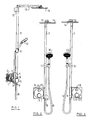
- FIG. 1 shows the side view of the shower arrangement proposed by the invention, as it would be arranged before or in a wall.
- the shower assembly contains a conventional Sanitary fitting 1, with connections 2 for a domestic installation.
- the sanitary fitting is intended for installation in a wall.
- a cover rosette 3 is arranged, whose back four is intended to bear against the front of the wall outside the recess in which the sanitary fitting 1 is installed.
- Through the cover escutcheon 3 grip actuators, to actuate the front two rotary knobs 4, 5 are attached.
- a pipe socket 6 is additionally arranged, at the top of a wall rod 7 is attached.
- connection 8 for a shower hose 9 is present on the opposite lower side of the cover rosette 3.
- the shower hose 9 hangs down freely, and its other end is provided with a hand shower 10 which is fixed in a holder 11.
- the holder 11 is attached to the wall bar 7 and can be moved there in height.
- the wall rod 7 which extends in a straight line, provided with a wall holder 12 which can be screwed to the wall and thereby fixed the wall bar 7.
- the wall rod 7 is angled at right angles and thereby forms a leg 13 which extends horizontally.
- a shower head 14 of a shower head is attached.
- the wall bar 7 is hollow, and it not only serves to attach the overhead shower 14, but also to their water supply.
- FIG. 2 shows a front view of the shower assembly of FIG. 1 So from the right in FIG. 1 ,
- the covering rosette 3 is square with the right attached pipe socket 6, which is offset from the front front of the covering rosette 3 to the front. Centered to the square cover rosette 3, a lid 15 is arranged, which is circular. Through this cover 15 through the sanitary fitting using the two knobs 4, 5 are operated.
- the pipe socket 6 has such a length that it is flush with the upper edge 16 and the lower edge 17 of the Abdeckrosette 3 both at its upper and at its lower end.
- FIG. 3 shows that the arrangement of the nozzle 6 can be solved laterally on the Abdeckros 3 also differently, namely just on the other side. This can be achieved by removing the covering rosette 3 and fixing it upside down again.
- the connection point for the shower hose which in the arrangement of the FIG. 2 is still down, therefore moves upward, and the connection point for the wall bar 7 down. This possibility is given by the fact that the two connections are identically faded out.
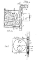
- FIG. 4 shows in enlarged scale the side view of the sanitary fitting 1, in the same representation as in FIG. 1 , but this time inside a flush-mounted box 16.
- the flush-mounted box 16 is shown in section.
- the sanitary fitting 1 is mounted within the flush-mounting box 16 so that the line connections with the sanitary fitting 1 through openings 17 in the side walls of the flush-mounting box 16 reach through.
- the sanitary fitting 1 is thus defined in the flush-mounted box 16.
- Rear side 4 of the Abdeckrosette 3 in the installed state abut the surface of the wall.
- the wall bar 7 still has a distance, as well as the connection 8 for the shower hose. 9
- the sanitary fitting 1 has at its front two ports 19, 20, which are controlled by the sanitary fitting. From each of the two ports 19, 20 leads a line piece 18 and 21 angled to the nozzle 6. One of the two line pieces, namely the in FIG. 5 Lower line piece 18, leads within the Abdeckrosette to the connection 8 for the shower hose, while the other line piece 21 leads to the wall rod 7. Both pipe sections 18, 21 contain two sub-elements, which are inserted into one another, so that they allow a length compensation. In the terminals 19, 20, the pipe sections 18, 21 are pivotally supported.
- FIG. 5 shows the front view of the arrangement with the cover removed 15. If the neck 6 are placed on the other side, this can be done by loosening screws 22. These screws 22 engage through slots 23 in tabs of Abdeckrosette 3 therethrough. As a result, an angular orientation of the cover escutcheon 3 with respect to the specified flush-mounted box 16 and the sanitary fitting 1 contained therein is possible. This change in orientation is made possible by the fact that the pipe sections 18, 21 allow a length compensation.
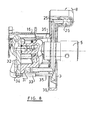
- FIG. 6 shows a section through the sanitary fitting and the flush-mounted box 16 in a different plane than the sectional plane of FIG. 4 ,
- the one leg 24 of the pipe section 18 can be seen, which engages in the port 19 of the sanitary fitting.
- the front section runs in FIG. 5 can still be seen in front view.
- the second part of the pipe section 18 engages, so that here a telescopic guide is given, which allows a length compensation.
- This second part of the line piece 18 also has a leg 25 bent at right angles, which engages in a receptacle 26.
- the receptacle 26 is in communication with the interior of the nozzle 6. In this way, a line connection between the sanitary fitting 1 and the connection 8 for the shower hose 9 is made. In the same way, there is also a connection between the sanitary fitting and the wall rod 7.
- FIG. 7 now shows a section through the connecting piece 6 in a plane parallel to the wall surface.
- the nozzle 6 has from its top and bottom side in each case a blind hole 27, 28.
- the two blind holes 27, 28 are thus separated from each other by a partition wall. Perpendicular to the axis of the nozzle 6 opens into the respective blind hole 27 and 28, a channel 29, 30, which is in communication with the end of a line piece 18, 21.
- FIG. 8 While in the embodiment of the FIG. 8 the cover rosette 3 is fastened by means of screws to the flush-mounting box 16, shows the FIG. 8 an embodiment with a different type of attachment.
- the fitting housing 31 For fixing the fitting housing 31 to the base part 32 are screws 33 which have an elongated screw head, which has a threaded bore on the threaded shank 34 side facing away. In this threaded hole in the screw head then the fastening screw 35 is screwed for the Abdeckros 3. This applies to all mounting screws 35. In addition to a greater stability of attachment this attachment has the advantage that the rosette 3 is attached to the valve, which is in the bushings for the lines against the wall-mounted flush-mounted box 16 is sound-decoupled.
- a foam rubber seal 36 is arranged in a groove for decoupling and isolating the covering rosette 3 with respect to the wall.
Landscapes
- Health & Medical Sciences (AREA)
- Life Sciences & Earth Sciences (AREA)
- Engineering & Computer Science (AREA)
- Hydrology & Water Resources (AREA)
- Public Health (AREA)
- Water Supply & Treatment (AREA)
- Bathtubs, Showers, And Their Attachments (AREA)
- Domestic Plumbing Installations (AREA)
Abstract
Description
- Die Erfindung betrifft eine Brausenanordnung mit einer Unterputzarmatur und einer mithilfe der Unterputzarmatur anzusteuernden Brause.
- Insbesondere in Altbauten oder bei der Modernisierung auch von neueren Gebäuden kann das Problem auftreten, dass nachträglich eine Brausenanordnung eingebaut werden soll, ohne allzu viel bauliche Änderungen vornehmen zu müssen. Der Platz für eine Unterputzarmatur ist dabei möglicherweise vorhanden oder kann geschaffen werden. In vielen Fällen ist eine Unterputzarmatur auch schon vorhanden, die eventuell nur ausgetauscht zu werden braucht.
- Es ist bereits eine Brausevorrichtung mit einer vor einer Wand angeordneten Mischbatterie bekannt an deren Oberseite eine Wasser führende Wandstange angeschlossen ist. Am Ende der Wandstange ist eine Kopfbrause angebracht. (
DE 19649004 A1 ). - Ebenfalls bekannt ist eine Sanitärarmatur zu Unterputzmontage (
DE 102004014126 B3 ), bei der ebenfalls an der Oberseite der unter Putz anzuordnenden Armatur ein Anschluss für eine Ausgangsleitung vorhanden ist. - Der Erfindung liegt die Aufgabe zu Grunde, eine insbesondere zum nachträglichen Einbau bestimmte Brausenanordnung zu schaffen, die mit einer Unterputzarmatur versehen ist.
- Zur Lösung dieser Aufgabe schlägt die Erfindung eine Brausenanordnung mit den im Anspruch 1 genannten Merkmalen vor. Weiterbildungen der Erfindung sind Gegenstand von Unteransprüchen.
- Auf diese Weise wird es möglich, einerseits eine Unterputzarmatur zu verwenden, andererseits aber ohne Aufstemmen der Wand eine auch optisch ansprechende Lösung zu finden, wie eine Brause mit Abstand von der Unterputzarmatur mit Wasser versorgt werden kann. Die Wandstange selbst, die als übliche Wandstange ausgebildet sein kann, dient gleichzeitig der Wasserführung zu der Kopfbrause und zu der Darstellung einer üblichen Wandstange, mit der Möglichkeit, dort Gegenstände anzubringen, die in der Höhe verstellbar sein sollen. Hierzu gehören beispielsweise Spiegel, Halter für Duschzusatzmittel oder dergleichen.
- Die Wandstange kann zusätzlich auch dazu dienen, die Halterung der Kopfbrause zu bilden, also nicht nur eine Möglichkeit, eine Kopfbrause an ihr anzubringen, sondern die Kopfbrause als Abschluss und Abschlusselement der Wandstange auszubilden. Insbesondere kann natürlich vorgesehen sein, die Wandstange in ihrem Endbereich in den Raum hinein abzuwinkeln oder abzubiegen, um die Kopfbrause auch mit einem horizontalen Abstand von der Wand anzuordnen.
- Um den Eindruck der üblichen Wandstange zu verstärken, kann in Weiterbildung vorgesehen sein, dass die Wandstange von ihrer Verbindung mit der Unterputzarmatur ausgehend geradlinig ausgebildet ist, so dass ihre Verbindung mit der Unterputzarmatur außerhalb der Wand angeordnet ist. Die Wandstange wächst praktisch aus der Unterputzarmatur nach oben heraus.
- Erfindungsgemäß kann die Wandstange so ausgebildet sein, dass sie direkt auf der Wandoberfläche aufliegt. Sie kann an dieser Wandoberfläche auch befestigt sein. Erfindungsgemäß kann aber in Weiterbildung auch vorgesehen sein, dass die Wandstange mit Abstand vor der Wand angeordnet ist, insbesondere mit einem solchen Abstand, der nicht nur eine leichte Reinigung hinter der Wandstange ermöglicht, sondern auch das Anbringen von Haltern, die um die Wandstange herum verdreht werden können. Damit sollen Gegenstände auch zur Seite verdreht werden können. Zur Verbindung mit der Wand kann dann im oberen Bereich ein Befestigungselement vorgesehen sein.
- Zur hydraulischen Verbindung zwischen der nicht speziell an die Wandstange angepasste Unterputzarmatur und der Wandstange ist ein Adapterelement vorgesehen, das diese Verbindung herstellt. Es kann insbesondere vorgesehen sein, dass das Adapterelement mindestens teilweise in einer Abdeckrosette der Unterputzarmatur enthalten ist. Diese Abdeckrosette kann so ausgestaltet sein, dass sie optisch mit der Wandstange eine Verbindung eingeht, insbesondere an dieser angepasst ist.
- Das Adapterelement kann dabei durch die Abdeckrosette hindurch führen.
- In nochmaliger Weiterbildung der Erfindung ist vorgesehen, dass die Brausenanordnung eine Einrichtung zum winkelmäßigen Ausrichten der Wandstange gegenüber der Unterputzarmatur aufweist. Da die Wandstange bis zu der Kopfbrause eine beachtliche Länge aufweist, kann ein Winkelfehler bei der Ausrichtung der Rosette, der an der Rückseite mit dem bloßen Auge nicht feststellbar ist, an der Wandstange aber dennoch festgestellt werden. Um eine solche und Schönheit zu vermeiden, wird von der Erfindung dieser Ausrichteinrichtung vorgeschlagen.
- Insbesondere kann das Adapterelement, das die hydraulische Verbindung herstellt, so ausgebildet sein, dass diese Ausrichtung dennoch zugelassen wird. Hierzu kann es verschiedene Möglichkeiten geben. Zum einen kann in dem Adapterelement beziehungsweise in der Rosette ein Leitungsstück zwischen dem Ausgang der Sanitärarmatur und der Wandstange angeordnet sein, das einen Längenausgleich und/oder einen Winkelausgleich ermöglicht. Für den Längenausgleich können zwei Rohrteile teleskopisch ineinander gesteckt sein. Für einen Winkelausgleich kann ein Leitungsende in eine Bohrung eingesetzt sein, der gegenüber es verdreht werden kann.
- Ebenfalls möglich ist die Verwendung eines verformbaren Leitungsstücks, beispielsweise eines Schlauchs.
- Bei einer Brauseanordnung, die sich insbesondere für den nachträglichen Einbau oder Anbau eignet, kann in Weiterbildung vorgesehen sein, dass die Brausenanordnung auch einen Anschluss für einen Brauseschlauch aufweist. Dies gilt insbesondere deswegen, weil man an der sowieso vorhandenen Wandstange ja dann auch einen Halter für eine Handbrause anbringen kann.
- Es hat sich als besonders sinnvoll herausgestellt, dass der Anschluss für einen Brauseschlauch außerhalb der die Unterputzarmatur aufnehmenden Wand angeordnet ist und insbesondere auch parallel zur Wandoberfläche verläuft. Aus optischen Gründen ist es vorzuziehen, wenn der Anschluss für den Brauseschlauch in eine der Wandstange entgegengesetzte Richtung zeigt.
- In nochmaliger Weiterbildung der Erfindung kann vorgesehen sein, dass der Anschluss für den Brauseschlauch in geradliniger Verlängerung der Wandstange angeordnet wird.
- Wegen einer einfachen Bedienung und einem geringen Platzbedarf kann erfindungsgemäß in Weiterbildung vorgesehen sein, dass die Wandstange und/oder der Anschluss für den Brauseschlauch seitlich an der Unterputzarmatur angeordnet ist.
- Da auch bei Verwendung eines Anschlusses für einen Brauseschlauch eine Winkelausrichtung sinnvoll ist, kann auch vorgesehen sein, dass zwischen dem Anschluss für den Brauseschlauch und der Sanitärarmatur ein Adapterelement vorhanden ist, das ebenfalls sinnvollerweise in der Rosette angeordnet ist und durch diese hindurchführt.
- Es wurde bereits erwähnt, dass es sinnvoll ist, wenn sowohl der Anschluss für die Wandstange als auch der Anschluss für den Brauseschlauch seitlich an der Armatur angeordnet sind. Erfindungsgemäß kann nun in Weiterbildung vorgesehen sein, das Adapterelement zwischen der Sanitärarmatur und der Wandstange beziehungsweise zwischen der Sanitärarmatur und dem Anschluss für den Brauseschlauch derart auszubilden, dass die Wandstange und/oder der Anschluss für den Brauseschlauch wahlweise rechts oder links seitlich an der Armatur anbringbar sind. Man kann daher beim Installieren noch entscheiden, wo genau die Wandstange sein soll. Um dies besonders einfach ermöglichen zu können, kann in Weiterbildung vorgesehen sein, dass der Anschluss für die Wandstange und der Anschluss für den Brauseschlauch identisch ausgebildet sind. Indiesem Fall braucht der Adapter nur umgedreht zu werden.
- Weitere Merkmale, Einzelheiten und Vorzüge der Erfindung ergeben sich aus den Ansprüchen und der Zusammenfassung, deren beider Wortlaut durch Bezugnahme zum Inhalt der Beschreibung gemacht wird, der folgenden Beschreibung bevorzugter Ausführungsformen der Erfindung sowie anhand der Zeichnung. Hierbei zeigen:
- Figur 1
- eine Seitenansicht einer Brauseanordnung nach der Erfindung;
- Figur 2
- die Ansicht der Anordnung der
Figur 1 von rechts inFigur 1 ; - Figur 3
- eine der
Figur 2 entsprechende Darstellung mit geänderter Anordnung der Wandstange; - Figur4
- in vergrößertem Maßstab eine Seitenansicht der Sanitärarmatur;
- Figur 5
- einen Querschnitt durch die Anordnung der
Figur 4 ; - Figur 6
- einen Schnitt durch die Sanitärarmatur;
- Figur 7
- einen weiteren Schnitt durch einen Teil der Sanitärarmatur;
- Figur 8
- einen der
Figur 6 entsprechenden Schnitt durch eine geänderte Ausführungsform. -
Figur 1 zeigt die Seitenansicht der von der Erfindung vorgeschlagenen Brausenanordnung, wie sie vor beziehungsweise in einer Wand angeordnet werden würde. Die Brausenanordnung enthält eine übliche Sanitärarmatur 1, mit Anschlüssen 2 für eine Hausinstallation. Die Sanitärarmatur ist zum Einbau in einer Wand bestimmt. An der Vorderseite der Sanitärarmatur 1 ist eine Abdeckrosette 3 angeordnet, deren Rückseite vier zur Anlage an der Vorderseite der Wand außerhalb der Vertiefung bestimmt ist, in der die Sanitärarmatur 1 eingebaut ist. Durch die Abdeckrosette 3 hindurch greifen Betäigungselemente, zu deren Betätigung an der Vorderseite zwei Drehknöpfe 4, 5 angebracht sind. An der Vorderseite der Abdeckrosette 3 ist zusätzlich dann noch ein Rohrstutzen 6 angeordnet, an dessen Oberseite eine Wandstange 7 angebracht ist. Auf der gegenüberliegenden unteren Seite der Abdeckrosette 3 ist ein Anschluss 8 für einen Brauseschlauch 9 vorhanden. Der Brauseschlauch 9 hängt frei herunter, und sein anderes Ende ist mit einer Handbrause 10 versehen, die in einer Halterung 11 festgelegt ist. Die Halterung 11 ist an der Wandstange 7 angebracht und kann dort in der Höhe verschoben werden. - Da der Rohrstutzen 6 und die Wandstange 7 vor der Vorderseite der Abdeckrosette 3 angebracht sind, ist zwischen der Rückseite der Wandstange 7 und der Wandoberfläche noch Platz vorhanden.
- In ihrem oberen Bereich ist die Wandstange 7, die geradlinig verläuft, mit einem Wandhalter 12 versehen, der an der Wand angeschraubt werden kann und dadurch die Wandstange 7 festgelegt. Oberhalb des Wandhalters 12 ist die Wandstange 7 rechtwinklig abgewinkelt und bildet dadurch einen Schenkel 13, der horizontal verläuft. Am Ende des Schenkels 13 der Wandstange 7 ist ein Brausekopf 14 einer Kopfbrause angebracht. Die Wandstange 7 ist hohl, und sie dient nicht nur zur Befestigung der Kopfbrause 14, sondern auch zu deren Wasserversorgung.
-
Figur 2 zeigt eine Frontansicht der Brausenanordnung derFigur 1 , also von rechts inFigur 1 . Die Abdeckrosette 3 ist quadratisch mit dem rechts angebrachten Rohrstutzen 6, der nach vorne gegenüber de Vorderseite der Abdeckrosette 3 versetzt ist. Mittig zu der quadratischen Abdeckrosette 3 ist ein Deckel 15 angeordnet, der kreisrund ist. Durch diesen Deckel 15 hindurch kann die Sanitärarmatur mithilfe der beiden Drehknöpfe 4, 5 betätigt werden. Der Rohrstutzen 6 weist eine solche Länge auf, dass er sowohl an seinem oberen als auch an seinem unteren Ende bündig mit der Oberkante 16 beziehungsweise der Unterkante 17 der Abdeckrosette 3 verläuft. - Am oberen Ende kann man sehen, dass der Schenkel 13 der Wandstange 7 zwar rechtwinklig gegenüber dem vertikalen Teil der Wandstange 7 verläuft, nicht aber senkrecht gegenüber der Oberfläche der Wand. Der Mittelpunkt der Kopfbrause 14 soll etwas seitlich versetzt sein.
-
Figur 3 zeigt, dass die Anordnung des Stutzens 6 seitlich an der Abdeckrosette 3 auch anders gelöst werden kann, nämlich gerade an der anderen Seite. Dies kann dadurch erreicht werden, dass die Abdeckrosette 3 abgenommen und umgedreht wieder befestigt wird. Die Anschlussstelle für den Brauseschlauch, die bei der Anordnung derFigur 2 noch unten ist, wandert daher nach oben, und die Anschlussstelle für die Wandstange 7 nach unten. Diese Möglichkeit wird dadurch gegeben, dass die beiden Anschlüsse identisch ausgebldet sind.
Figur 4 zeigt in vergrößertem Maßstab die Seitenansicht der Sanitärarmatur 1, in der gleichen Darstellung wie inFigur 1 , jedoch diesmal innerhalb eines Unterputzkastens 16. Der Unterputzkasten 16 ist im Schnitt gezeigt. Die Sanitärarmatur 1 ist so innerhalb des Unterputzkastens 16 befestigt, dass die Leitungsverbindungen mit der Sanitärarmatur 1 durch Öffnungen 17 in den Seitenwänden des Unterputzkastens 16 hindurch greifen. Die Sanitärarmatur 1 ist also in dem Unterputzkasten 16 festgelegt. Wie bereits erwähnt, soll die Rückseite 4 der Abdeckrosette 3 im Einbauzustand an der Oberfläche der Wand anliegen. Gegenüber der Vorderseite der Abdeckrosette 3 weist die Wandstange 7 noch einen Abstand auf, ebenso der Anschluss 8 für den Brauseschlauch 9. - Von der Vorderseite der Sanitärarmatur 1 aus führt ein im Teilschnitt dargestelltes Leitungsstück 18 durch die Abdeckrosette 3 hindurch zu der Wandstange 7 und dem Brauseanschluss 8. Dies wird in der Darstellung der
Figur 5 deutlicher sichtbar. - Die Sanitärarmatur 1 weist an ihrer Vorderseite zwei Anschlüsse 19, 20 auf, die durch die Sanitärarmatur angesteuert werden. Von jedem der beiden Anschlüsse 19, 20 führt ein Leitungsstück 18 beziehungsweise 21 abgewinkelt zu dem Stutzen 6. Eines der beiden Leitungsstücke, nämlich das in
Figur 5 untere Leitungsstück 18, führt innerhalb der Abdeckrosette zu dem Anschluss 8 für den Brauseschlauch, während das andere Leitungsstück 21 zu der Wandstange 7 führt. Beide Leitungsstücke 18, 21 enthalten zwei Teilelemente, die ineinander gesteckt sind, so dass sie einen Längenausgleich ermöglichen. In den Anschlüssen 19, 20 sind die Leitungsstücke 18, 21 verschwenkbar gehaltert. - Die
Figur 5 zeigt die vordere Ansicht der Anordnung bei abgenommenem Deckel 15. Soll der Stutzen 6 auf die andere Seite gelegt werden, so kann dies durch Lösen von Schrauben 22 geschehen. Diese Schrauben 22 greifen durch Langlöcher 23 in Laschen der Abdeckrosette 3 hindurch. Dadurch ist auch eine winkelmäßige Ausrichtung der Abdeckrosette 3 gegenüber dem festgelegten Unterputzkasten 16 und der darin enthaltenen Sanitärarmatur 1 möglich. Diese Änderung der Ausrichtung wird dadurch ermöglicht, dass die Leitungsstücke 18, 21 einen Längenausgleich zulassen. - Die
Figur 6 zeigt einen Schnitt durch die Sanitärarmatur und den Unterputzkasten 16 in einer anderen Ebene als der Schnittebene derFigur 4 . Hier ist der eine Schenkel 24 des Leitungsstücks 18 zu sehen, der in den Anschluss 19 der Sanitärarmatur eingreift. Senkrecht zu diesem Abschnitt 24 verläuft der vordere Abschnitt, der inFigur 5 noch in Stirnansicht zu sehen ist. In diesen Abschnitt greift der zweite Teil des Leitungsstücks 18 ein, so dass hier eine teleskopische Führung gegeben ist, die einen Längenausgleich ermöglicht. Auch dieser zweite Teil des Leitungsstücks 18 weist einen rechtwinklig abgebogenen Schenkel 25 auf, der in eine Aufnahme 26 eingreift. Die Aufnahme 26 steht mit dem Inneren des Stutzens 6 in Verbindung. Auf diese Weise wird eine Leitungsverbindung zwischen der Sanitärarmatur 1 und dem Anschluss 8 für den Brauseschlauch 9 hergestellt. In der gleichen Weise erfolgt auch eine Verbindung zwischen der Sanitärarmatur und der Wandstange 7. -
Figur 7 zeigt nun noch einen Schnitt durch den Anschlussstutzen 6 in einer Ebene parallel zu der Wandoberfläche. Der Stutzen 6 weist von seiner Oberseite und seiner Unterseite her jeweils eine Sacklochbohrung 27, 28 auf. Die beiden Sacklochbohrungen 27, 28 sind also durch eine Trennwand voneinander getrennt. Senkrecht zur Achse des Stutzens 6 mündet in die jeweilige Sacklochbohrung 27 beziehungsweise 28 ein Kanal 29, 30, der mit dem Ende eines Leitungsstücks 18, 21 in Verbindung steht. - Die eigentlichen Anschlüsse für die Wandstange 7 und den Brauseschlauch 9 sind identisch ausgebildet, so dass ihre Rollen vertauscht werden können.
- Während bei der Ausführungsform der
Figur 8 die Abdeckrosette 3 mithilfe von Schrauben an dem Unterputzkasten 16 befestigt ist, zeigt dieFigur 8 eine Ausführungsform mit einer anderen Art der Befestigung. - Zur Festlegung des Armaturengehäuses 31 an dem Basisteil 32 dienen Schrauben 33, die einen verlängerten Schraubenkopf aufweisen, der auf der dem Gewindeschaft 34 abgewandten Seite eine Gewindebohrung aufweist. In diese Gewindebohrung im Schraubenkopf ist dann die Befestigungsschraube 35 für die Abdeckrosette 3 eingeschraubt. Dies gilt für alle Befestigungsschrauben 35. Neben einer größeren Stabilität der Anbringung hat dieser Anbringungsart den Vorteil, dass die Rosette 3 an der Armatur befestigt wird, die in den Durchführungen für die Leitungen gegenüber dem mit der Wand verbundenen Unterputzkasten 16 schallentkoppelt ist.
- Auf der Rückseite der Abdeckrosette 3 ist eine Schaumgummidichtung 36 in einer Nut angeordnet, zur Entkopplung und Isolierung der Abdeckrosette 3 gegenüber der Wand.
Claims (15)
- Brausenanordnung, mit1.1 einer Unterputzarmatur (1),1.2 einer mit der Unterputzarmatur (1) mechanisch und hydraulisch verbundenen wasserführenden Wandstange (7), die1.3 außerhalb der die Unterputzarmatur (1) aufweisenden Wand anzuordnen ist, sowie mit1.4 einer an der Wandstange (7) angebrachten und durch diese hindurch mit Wasser versorgten Kopfbrause (14), sowie mit1.5 einem Adapterelement zwischen der Unterputzarmatur (1) und der Wandstange (7) und1.6 einer Einrichtung zum winkelmäßigen Ausrichten der Wandstange (7), ggf. mit der Rosette (3), gegenüber der Unterputzarmatur (1)...
- Brausenanordnung nach Anspruch 1, bei der die Kopfbrause (14) an einem von der Wand abragenden Ende der Wandstange (7) angebracht ist.
- Brausenanordnung nach Anspruch 1 oder 2, bei der die Wandstange (7) von ihrer Verbindung mit der Unterputzarmatur (1) ausgehend geradlinig ausgebildet ist derart, dass ihre Verbindung mit der Unterputzarmatur (1) außerhalb der Wand angeordnet ist.
- Brausenanordnung nach einem der vorhergehenden Ansprüche, bei der die Wandstange (7) mit Abstand vor der Wand angeodnet ist.
- Brausenanordnung nach einem der vorhergehenden Ansprüche, bei der das Adapterelement mindestens teilweise in einer Abdeckrosette (3) der Unterputzarmatur (1) enthalten ist und/oder durch eine Abdeckrosette (3) der Unterputzarmatur (1) hindurchführt.
- Brausenanordnung nach einem der vorhergehenden Ansprüche, bei der das Adapterelement derart ausgebildet ist, dass es das Ausrichten der Wandstange (7) gegenüber der Unterputzarmatur (1) zulässt.
- Brausenanordnung nach Anspruch 6, bei der das Adapterelement zwischen der Sanitärarmatur (1) und der Wandstange (7) beziehungsweise zwischen der Sanitärarmatur (1) und einem Anschluss ein Leitungsstück (18, 21) mit Längenausgleich und/oder Winkelausgleich aufweist.
- Brausenanordnung nach Anspruch 7, bei der das Leitungsstück verformbar ausgebildet ist.
- Brausenanordnung nach Anspruch 7 oder 8, bei der das Leitungsstück (18, 21) in der Abdeckrosette (3) fixiert ist
- Brausenanordnung nach einem der vorhergehenden Ansprüche, mit einem Anschluss (8) für einen Brauseschlauch (9), wobei insbesondere der Anschluss (8) für den Brauseschlauch (9) außerhalb der die Unterputzarmatur (1) aufnehmenden Wand angeordnet ist und parallel zur Wandoberfläche verläuft.
- Brausenanordnung nach Anspruch 10, bei der der Anschluss (8) für den Brauseschlauch (9) in eine der Wandstange (7) entgegengesetzte Richtung zeigt und insbesondere in geradliniger Verlängerung der Wandstange (7) angeordnet ist.
- Brausenanordnung nach einem der vorhergehenden Ansprüche, bei der die Wandstange (7) und/oder der Anschluss (8) für den Brauseschlauch (9) seitlich an der Unterputzarmatur angeordnet ist.
- Brausenanordnung nach einem der Ansprüche 10 bis 12, mit einem Adapterelement zwischen der Unterputzarmatur (1) und dem Anschluss (8) für den Brauseschlauch (9).
- Brausenanordnung nach einem der vorhergenden Ansprüche, bei der das Adapterelement zwischen der Sanitärarmatur (1) und der Wandstange (7) beziehungsweise zwischen der Sanitärarmatur (1) und dem Anschluss (8) für den Brauseschlauch (9) derart ausgebildet ist, dass die Wandstange (7) und/oder der Anschluss (8) für den Brauseschlauch (9) wahlweise rechts oder links seitlich an der Armatur anbringbar sind.
- Brausenanordnung nach einem der Ansprüche 10 bis 14, bei der der Anschluss für die Wandstange (7) und der Anschluss (8) für den Brauseschlauch (9) identisch ausgebildet sind.
Priority Applications (1)
| Application Number | Priority Date | Filing Date | Title |
|---|---|---|---|
| PL09167263T PL2154297T3 (pl) | 2008-08-15 | 2009-08-05 | Układ natryskowy |
Applications Claiming Priority (1)
| Application Number | Priority Date | Filing Date | Title |
|---|---|---|---|
| DE102008039797A DE102008039797A1 (de) | 2008-08-15 | 2008-08-15 | Brausenanordnung |
Publications (3)
| Publication Number | Publication Date |
|---|---|
| EP2154297A2 true EP2154297A2 (de) | 2010-02-17 |
| EP2154297A3 EP2154297A3 (de) | 2011-08-03 |
| EP2154297B1 EP2154297B1 (de) | 2016-11-02 |
Family
ID=41152198
Family Applications (1)
| Application Number | Title | Priority Date | Filing Date |
|---|---|---|---|
| EP09167263.4A Not-in-force EP2154297B1 (de) | 2008-08-15 | 2009-08-05 | Brauseanordnung |
Country Status (8)
| Country | Link |
|---|---|
| US (1) | US8429769B2 (de) |
| EP (1) | EP2154297B1 (de) |
| CN (1) | CN101672053B (de) |
| DE (1) | DE102008039797A1 (de) |
| DK (1) | DK2154297T3 (de) |
| ES (1) | ES2608983T3 (de) |
| PL (1) | PL2154297T3 (de) |
| PT (1) | PT2154297T (de) |
Cited By (2)
| Publication number | Priority date | Publication date | Assignee | Title |
|---|---|---|---|---|
| WO2012083193A1 (en) | 2010-12-17 | 2012-06-21 | Kohler Co. | Shower bar system |
| US9068325B2 (en) | 2012-03-21 | 2015-06-30 | Speakman Company | Adapter for attachment to water supply pipes and exterior conduits |
Families Citing this family (31)
| Publication number | Priority date | Publication date | Assignee | Title |
|---|---|---|---|---|
| DE102010002535B4 (de) | 2010-03-03 | 2017-08-31 | Hansgrohe Se | Sanitärarmatur mit relingartigem Bügel |
| DE102010023962A1 (de) * | 2010-06-16 | 2011-12-22 | Neoperl Gmbh | Dichtring, Durchflussmengenregler sowie Brausearmatur mit einem Durchflussmengenregler |
| US9468939B2 (en) | 2012-03-12 | 2016-10-18 | Kohler Co. | Faceplate for shower device |
| USD692527S1 (en) | 2012-03-12 | 2013-10-29 | Kohler Co. | Shower faceplate |
| DE102012008406A1 (de) | 2012-04-27 | 2013-10-31 | Grohe Ag | Wandbefestigung für ein Duschsystem |
| US9687859B2 (en) | 2012-11-16 | 2017-06-27 | Kohler Co. | Shower device |
| USD715896S1 (en) | 2013-03-15 | 2014-10-21 | Kohler Co. | Shower faceplate |
| USD716415S1 (en) | 2013-03-15 | 2014-10-28 | Kohler Co. | Shower faceplate |
| USD740917S1 (en) | 2013-03-16 | 2015-10-13 | Kohler Co. | Shower faceplate for shower device |
| USD715398S1 (en) | 2013-03-16 | 2014-10-14 | Kohler Co. | Shower faceplate |
| CN103277577A (zh) * | 2013-06-04 | 2013-09-04 | 苏州原点工业设计有限公司 | 一种水龙头 |
| US9410309B2 (en) | 2013-07-31 | 2016-08-09 | Waxman Consumer Products Group Inc. | Wall shower bar assembly |
| USD719240S1 (en) | 2013-08-23 | 2014-12-09 | Kohler Co. | Shower device |
| US9707574B2 (en) | 2014-06-16 | 2017-07-18 | Kohler Co. | Diverter valve assembly and shower system |
| US10322058B1 (en) * | 2015-09-08 | 2019-06-18 | Lianna Patch | Sexual stimulation device |
| US10245610B2 (en) | 2015-12-07 | 2019-04-02 | Delta Faucet Company | On-wall shower system |
| US10352025B2 (en) | 2016-04-29 | 2019-07-16 | Moen Incorporated | Plumbing fixture fitting with mounting system |
| USD960302S1 (en) | 2017-06-28 | 2022-08-09 | Phoenix Industries Pty Ltd | Shower head |
| US10376904B2 (en) * | 2017-07-24 | 2019-08-13 | Diane Jack | Head and shoulder showerhead system |
| US10655310B2 (en) | 2018-01-05 | 2020-05-19 | Delta Faucet Company | Shower bar system |
| US11105075B2 (en) | 2018-05-08 | 2021-08-31 | Delta Faucet Company | Adjustable height shower head assembly |
| GB2574420B (en) | 2018-06-05 | 2020-12-16 | Kohler Mira Ltd | Diverter for ablutionary installation |
| USD939047S1 (en) | 2019-02-22 | 2021-12-21 | Phoenix Industries Pty Ltd | Rail shower |
| USD954900S1 (en) * | 2019-02-22 | 2022-06-14 | Phoenix Industries Pty Ltd | Rail shower |
| USD943709S1 (en) * | 2019-02-22 | 2022-02-15 | Phoenix Industries Pty Ltd | Twin showers |
| USD939046S1 (en) | 2019-02-22 | 2021-12-21 | Phoenix Industries Pty Ltd | Hand shower |
| USD942599S1 (en) | 2019-02-22 | 2022-02-01 | Phoenix Industries Pty Ltd | Hand shower bracket |
| USD939664S1 (en) | 2019-02-22 | 2021-12-28 | Phoenix Industries Pty Ltd | Hand shower |
| USD972922S1 (en) | 2019-02-22 | 2022-12-20 | Phoenix Industries Pty Ltd | Hand shower bracket |
| US11951493B2 (en) * | 2019-07-21 | 2024-04-09 | Delta Faucet Company | Exposed secondary shower system |
| USD965741S1 (en) * | 2022-03-06 | 2022-10-04 | Wenzhou Maitewusi Household Co., Ltd | Shower system |
Citations (2)
| Publication number | Priority date | Publication date | Assignee | Title |
|---|---|---|---|---|
| DE19649004A1 (de) | 1996-11-27 | 1998-05-28 | Grohe Armaturen Friedrich | Brausevorrichtung |
| DE102004014126B3 (de) | 2004-03-23 | 2005-11-24 | Schell Gmbh & Co. Kg | Sanitär-Armatur zur Unterputz-Montage |
Family Cites Families (18)
| Publication number | Priority date | Publication date | Assignee | Title |
|---|---|---|---|---|
| US2336402A (en) * | 1940-08-04 | 1943-12-07 | Albert G Kaiser | Shower bath mechanism |
| US2846691A (en) * | 1956-11-19 | 1958-08-12 | Milwaukee Faucets | Spout-shower plumbing fixture |
| US3564621A (en) * | 1968-09-09 | 1971-02-23 | Samuel L Fletcher | Shower fixture |
| SE386701B (sv) * | 1973-10-29 | 1976-08-16 | L J Yxfeldt | Duschanordning |
| US3982285A (en) * | 1975-07-17 | 1976-09-28 | Roberts Jr R Douglas | Combined grab bar and shower head fixture |
| DE3327829A1 (de) * | 1983-08-02 | 1985-02-14 | Hansa Metallwerke Ag, 7000 Stuttgart | Sanitaere unterputzarmatur |
| GB2251378B (en) * | 1990-12-14 | 1994-11-23 | Christopher Terrell | Personal shower |
| US6438767B1 (en) * | 2001-04-26 | 2002-08-27 | I. W. Industries, Inc. | Adjustable height showerhead |
| DE20115533U1 (de) * | 2001-09-20 | 2002-01-03 | Aloys F. Dornbracht GmbH & Co. KG, 58640 Iserlohn | Vorrichtung zum Verteilen von Wasser |
| JP3747893B2 (ja) * | 2002-02-06 | 2006-02-22 | 東陶機器株式会社 | シャワー装置 |
| DE20304879U1 (de) | 2003-03-25 | 2003-06-05 | Delvac Sanitär GmbH, 31632 Husum | Duschvorrichtung |
| DE60316855D1 (de) | 2003-09-30 | 2007-11-22 | Rubinetterie Cristina S P A | Duschsäule |
| DE20319171U1 (de) * | 2003-12-10 | 2004-02-26 | Yang, Tsai Chen, Lugang | Duschvorrichtung mit Einstellmechanismus |
| DE102004010327A1 (de) * | 2004-02-25 | 2005-09-15 | Hansgrohe Ag | Brauseanordnung |
| KR100559161B1 (ko) * | 2004-11-23 | 2006-03-13 | 주식회사 피아이피 | 벽체매립형 수전함 |
| DE102005002627A1 (de) | 2005-01-12 | 2006-07-20 | Hansgrohe Ag | Duscheinrichtung |
| DE102005011294A1 (de) * | 2005-03-04 | 2006-09-07 | Hansgrohe Ag | Brauseeinrichtung |
| CN201007390Y (zh) * | 2006-12-27 | 2008-01-16 | 和成欣业股份有限公司 | 水龙头结构 |
-
2008
- 2008-08-15 DE DE102008039797A patent/DE102008039797A1/de not_active Withdrawn
-
2009
- 2009-08-03 US US12/534,391 patent/US8429769B2/en not_active Expired - Fee Related
- 2009-08-05 PL PL09167263T patent/PL2154297T3/pl unknown
- 2009-08-05 EP EP09167263.4A patent/EP2154297B1/de not_active Not-in-force
- 2009-08-05 ES ES09167263.4T patent/ES2608983T3/es active Active
- 2009-08-05 PT PT91672634T patent/PT2154297T/pt unknown
- 2009-08-05 DK DK09167263.4T patent/DK2154297T3/en active
- 2009-08-14 CN CN200910166735.0A patent/CN101672053B/zh not_active Expired - Fee Related
Patent Citations (2)
| Publication number | Priority date | Publication date | Assignee | Title |
|---|---|---|---|---|
| DE19649004A1 (de) | 1996-11-27 | 1998-05-28 | Grohe Armaturen Friedrich | Brausevorrichtung |
| DE102004014126B3 (de) | 2004-03-23 | 2005-11-24 | Schell Gmbh & Co. Kg | Sanitär-Armatur zur Unterputz-Montage |
Cited By (10)
| Publication number | Priority date | Publication date | Assignee | Title |
|---|---|---|---|---|
| WO2012083193A1 (en) | 2010-12-17 | 2012-06-21 | Kohler Co. | Shower bar system |
| EP2652215A4 (de) * | 2010-12-17 | 2016-09-07 | Kohler Co | Duschstangensystem |
| US9677256B2 (en) | 2010-12-17 | 2017-06-13 | Kohler Co. | Shower bar system |
| US10024038B2 (en) | 2010-12-17 | 2018-07-17 | Kohler Co. | Shower bar system |
| US10422113B2 (en) | 2010-12-17 | 2019-09-24 | Kohler Co. | Shower bar system |
| US11174627B2 (en) | 2010-12-17 | 2021-11-16 | Kohler Co. | Shower bar system |
| US11624175B2 (en) | 2010-12-17 | 2023-04-11 | Kohler Co. | Shower bar system |
| US11761186B2 (en) | 2010-12-17 | 2023-09-19 | Kohler Co. | Shower bar system |
| US12049747B2 (en) | 2010-12-17 | 2024-07-30 | Kohler Co. | Shower bar system |
| US9068325B2 (en) | 2012-03-21 | 2015-06-30 | Speakman Company | Adapter for attachment to water supply pipes and exterior conduits |
Also Published As
| Publication number | Publication date |
|---|---|
| US8429769B2 (en) | 2013-04-30 |
| CN101672053B (zh) | 2015-02-18 |
| EP2154297A3 (de) | 2011-08-03 |
| EP2154297B1 (de) | 2016-11-02 |
| CN101672053A (zh) | 2010-03-17 |
| DE102008039797A1 (de) | 2010-02-25 |
| US20100037389A1 (en) | 2010-02-18 |
| ES2608983T3 (es) | 2017-04-17 |
| PL2154297T3 (pl) | 2017-04-28 |
| PT2154297T (pt) | 2017-02-03 |
| DK2154297T3 (en) | 2017-02-06 |
Similar Documents
| Publication | Publication Date | Title |
|---|---|---|
| EP2154297B1 (de) | Brauseanordnung | |
| EP2101002B1 (de) | Einbaukasten zum variablen Einbau von Sanitärarmaturen | |
| EP2236683A1 (de) | Duschrinnenanordnung für Wandeinbau | |
| DE102006033352B4 (de) | Sanitäre Unterputzarmatur mit einem Basiskörper | |
| EP2053168B1 (de) | Wandeinbau-Ablaufgarnitur für einen sanitären Ablauf | |
| WO2015042726A1 (de) | Montageplatte für einen klosettkörper | |
| DE202013001133U1 (de) | WC mit Unterdusche | |
| EP3733986B1 (de) | Montagerahmen für einen sanitärartikel mit einer elektrodose | |
| EP1723285B1 (de) | Brauseanordnung | |
| DE19710647A1 (de) | Waschbeckeninstallation | |
| DE19856157B4 (de) | Anschlussblock für Sanitärarmaturen | |
| EP0790448B1 (de) | Sanitärarmatur | |
| DE19943307A1 (de) | Schutzeinrichtung für Sanitärarmaturen | |
| AT396269B (de) | Einrichtung zur montage einer handbrause an der seite einer badewanne | |
| WO2006108605A1 (de) | System mit einer sanitären armatur und einem wasserauslass an einer wand und einer plattenartigen abdeckung | |
| EP1570136A1 (de) | Brausehalter | |
| EP1435414B1 (de) | Sanitärhalterung | |
| AT410812B (de) | Anordnung zur aufnahme von anschluss- und ableitungselementen | |
| DE20312627U1 (de) | Anordnung aus einer Sanitärarmatur und einer Befestigungseinrichtung für ein Accessoireteil | |
| EP0790359A1 (de) | Befestigungsvorrichtung für ein Sanitärelement | |
| DE102022119002A1 (de) | Unterputzbox für einen Anschlusskörper zum Anschluss einer Armatur | |
| EP3957801A1 (de) | Verbindungsvorrichtung zwischen einem unterputzwasserkasten und einer spüle | |
| DE10312863A1 (de) | Brausenanordnung | |
| EP1441078A2 (de) | Anordnung eines Brauseschlauchaufrollers in einem Hartschaum-Badewannenträger | |
| DE3907337A1 (de) | Anschlussdose fuer wasserleitungsinstallationen |
Legal Events
| Date | Code | Title | Description |
|---|---|---|---|
| PUAI | Public reference made under article 153(3) epc to a published international application that has entered the european phase |
Free format text: ORIGINAL CODE: 0009012 |
|
| AK | Designated contracting states |
Kind code of ref document: A2 Designated state(s): AT BE BG CH CY CZ DE DK EE ES FI FR GB GR HR HU IE IS IT LI LT LU LV MC MK MT NL NO PL PT RO SE SI SK SM TR |
|
| AX | Request for extension of the european patent |
Extension state: AL BA RS |
|
| PUAL | Search report despatched |
Free format text: ORIGINAL CODE: 0009013 |
|
| AK | Designated contracting states |
Kind code of ref document: A3 Designated state(s): AT BE BG CH CY CZ DE DK EE ES FI FR GB GR HR HU IE IS IT LI LT LU LV MC MK MT NL NO PL PT RO SE SI SK SM TR |
|
| AX | Request for extension of the european patent |
Extension state: AL BA RS |
|
| RIC1 | Information provided on ipc code assigned before grant |
Ipc: E03C 1/04 20060101AFI20110627BHEP Ipc: E03C 1/06 20060101ALI20110627BHEP |
|
| 17P | Request for examination filed |
Effective date: 20120104 |
|
| 17Q | First examination report despatched |
Effective date: 20120518 |
|
| RAP1 | Party data changed (applicant data changed or rights of an application transferred) |
Owner name: HANSGROHE SE |
|
| GRAP | Despatch of communication of intention to grant a patent |
Free format text: ORIGINAL CODE: EPIDOSNIGR1 |
|
| INTG | Intention to grant announced |
Effective date: 20160523 |
|
| GRAS | Grant fee paid |
Free format text: ORIGINAL CODE: EPIDOSNIGR3 |
|
| GRAA | (expected) grant |
Free format text: ORIGINAL CODE: 0009210 |
|
| AK | Designated contracting states |
Kind code of ref document: B1 Designated state(s): AT BE BG CH CY CZ DE DK EE ES FI FR GB GR HR HU IE IS IT LI LT LU LV MC MK MT NL NO PL PT RO SE SI SK SM TR |
|
| REG | Reference to a national code |
Ref country code: GB Ref legal event code: FG4D Free format text: NOT ENGLISH |
|
| REG | Reference to a national code |
Ref country code: AT Ref legal event code: REF Ref document number: 842007 Country of ref document: AT Kind code of ref document: T Effective date: 20161115 Ref country code: CH Ref legal event code: EP |
|
| REG | Reference to a national code |
Ref country code: IE Ref legal event code: FG4D Free format text: LANGUAGE OF EP DOCUMENT: GERMAN |
|
| REG | Reference to a national code |
Ref country code: DE Ref legal event code: R096 Ref document number: 502009013291 Country of ref document: DE |
|
| REG | Reference to a national code |
Ref country code: CH Ref legal event code: NV Representative=s name: DR. LUSUARDI AG, CH |
|
| REG | Reference to a national code |
Ref country code: NL Ref legal event code: FP |
|
| REG | Reference to a national code |
Ref country code: PT Ref legal event code: SC4A Ref document number: 2154297 Country of ref document: PT Date of ref document: 20170203 Kind code of ref document: T Free format text: AVAILABILITY OF NATIONAL TRANSLATION Effective date: 20170123 |
|
| REG | Reference to a national code |
Ref country code: DK Ref legal event code: T3 Effective date: 20170130 |
|
| PG25 | Lapsed in a contracting state [announced via postgrant information from national office to epo] |
Ref country code: LV Free format text: LAPSE BECAUSE OF FAILURE TO SUBMIT A TRANSLATION OF THE DESCRIPTION OR TO PAY THE FEE WITHIN THE PRESCRIBED TIME-LIMIT Effective date: 20161102 |
|
| REG | Reference to a national code |
Ref country code: LT Ref legal event code: MG4D |
|
| REG | Reference to a national code |
Ref country code: ES Ref legal event code: FG2A Ref document number: 2608983 Country of ref document: ES Kind code of ref document: T3 Effective date: 20170417 |
|
| PG25 | Lapsed in a contracting state [announced via postgrant information from national office to epo] |
Ref country code: GR Free format text: LAPSE BECAUSE OF FAILURE TO SUBMIT A TRANSLATION OF THE DESCRIPTION OR TO PAY THE FEE WITHIN THE PRESCRIBED TIME-LIMIT Effective date: 20170203 Ref country code: NO Free format text: LAPSE BECAUSE OF FAILURE TO SUBMIT A TRANSLATION OF THE DESCRIPTION OR TO PAY THE FEE WITHIN THE PRESCRIBED TIME-LIMIT Effective date: 20170202 Ref country code: LT Free format text: LAPSE BECAUSE OF FAILURE TO SUBMIT A TRANSLATION OF THE DESCRIPTION OR TO PAY THE FEE WITHIN THE PRESCRIBED TIME-LIMIT Effective date: 20161102 Ref country code: SE Free format text: LAPSE BECAUSE OF FAILURE TO SUBMIT A TRANSLATION OF THE DESCRIPTION OR TO PAY THE FEE WITHIN THE PRESCRIBED TIME-LIMIT Effective date: 20161102 |
|
| PG25 | Lapsed in a contracting state [announced via postgrant information from national office to epo] |
Ref country code: IS Free format text: LAPSE BECAUSE OF FAILURE TO SUBMIT A TRANSLATION OF THE DESCRIPTION OR TO PAY THE FEE WITHIN THE PRESCRIBED TIME-LIMIT Effective date: 20170302 Ref country code: HR Free format text: LAPSE BECAUSE OF FAILURE TO SUBMIT A TRANSLATION OF THE DESCRIPTION OR TO PAY THE FEE WITHIN THE PRESCRIBED TIME-LIMIT Effective date: 20161102 |
|
| PG25 | Lapsed in a contracting state [announced via postgrant information from national office to epo] |
Ref country code: RO Free format text: LAPSE BECAUSE OF FAILURE TO SUBMIT A TRANSLATION OF THE DESCRIPTION OR TO PAY THE FEE WITHIN THE PRESCRIBED TIME-LIMIT Effective date: 20161102 Ref country code: CZ Free format text: LAPSE BECAUSE OF FAILURE TO SUBMIT A TRANSLATION OF THE DESCRIPTION OR TO PAY THE FEE WITHIN THE PRESCRIBED TIME-LIMIT Effective date: 20161102 Ref country code: EE Free format text: LAPSE BECAUSE OF FAILURE TO SUBMIT A TRANSLATION OF THE DESCRIPTION OR TO PAY THE FEE WITHIN THE PRESCRIBED TIME-LIMIT Effective date: 20161102 Ref country code: SK Free format text: LAPSE BECAUSE OF FAILURE TO SUBMIT A TRANSLATION OF THE DESCRIPTION OR TO PAY THE FEE WITHIN THE PRESCRIBED TIME-LIMIT Effective date: 20161102 |
|
| REG | Reference to a national code |
Ref country code: DE Ref legal event code: R097 Ref document number: 502009013291 Country of ref document: DE |
|
| REG | Reference to a national code |
Ref country code: FR Ref legal event code: PLFP Year of fee payment: 9 |
|
| PG25 | Lapsed in a contracting state [announced via postgrant information from national office to epo] |
Ref country code: SM Free format text: LAPSE BECAUSE OF FAILURE TO SUBMIT A TRANSLATION OF THE DESCRIPTION OR TO PAY THE FEE WITHIN THE PRESCRIBED TIME-LIMIT Effective date: 20161102 Ref country code: BG Free format text: LAPSE BECAUSE OF FAILURE TO SUBMIT A TRANSLATION OF THE DESCRIPTION OR TO PAY THE FEE WITHIN THE PRESCRIBED TIME-LIMIT Effective date: 20170202 |
|
| PLBE | No opposition filed within time limit |
Free format text: ORIGINAL CODE: 0009261 |
|
| STAA | Information on the status of an ep patent application or granted ep patent |
Free format text: STATUS: NO OPPOSITION FILED WITHIN TIME LIMIT |
|
| 26N | No opposition filed |
Effective date: 20170803 |
|
| PGFP | Annual fee paid to national office [announced via postgrant information from national office to epo] |
Ref country code: FI Payment date: 20170821 Year of fee payment: 9 Ref country code: ES Payment date: 20170901 Year of fee payment: 9 |
|
| PG25 | Lapsed in a contracting state [announced via postgrant information from national office to epo] |
Ref country code: SI Free format text: LAPSE BECAUSE OF FAILURE TO SUBMIT A TRANSLATION OF THE DESCRIPTION OR TO PAY THE FEE WITHIN THE PRESCRIBED TIME-LIMIT Effective date: 20161102 |
|
| PGFP | Annual fee paid to national office [announced via postgrant information from national office to epo] |
Ref country code: TR Payment date: 20170802 Year of fee payment: 9 Ref country code: PL Payment date: 20170725 Year of fee payment: 9 Ref country code: DK Payment date: 20170824 Year of fee payment: 9 Ref country code: PT Payment date: 20170726 Year of fee payment: 9 |
|
| PG25 | Lapsed in a contracting state [announced via postgrant information from national office to epo] |
Ref country code: MC Free format text: LAPSE BECAUSE OF FAILURE TO SUBMIT A TRANSLATION OF THE DESCRIPTION OR TO PAY THE FEE WITHIN THE PRESCRIBED TIME-LIMIT Effective date: 20161102 |
|
| REG | Reference to a national code |
Ref country code: IE Ref legal event code: MM4A |
|
| PG25 | Lapsed in a contracting state [announced via postgrant information from national office to epo] |
Ref country code: LU Free format text: LAPSE BECAUSE OF NON-PAYMENT OF DUE FEES Effective date: 20170805 |
|
| PG25 | Lapsed in a contracting state [announced via postgrant information from national office to epo] |
Ref country code: IE Free format text: LAPSE BECAUSE OF NON-PAYMENT OF DUE FEES Effective date: 20170805 |
|
| REG | Reference to a national code |
Ref country code: FR Ref legal event code: PLFP Year of fee payment: 10 |
|
| PG25 | Lapsed in a contracting state [announced via postgrant information from national office to epo] |
Ref country code: MT Free format text: LAPSE BECAUSE OF FAILURE TO SUBMIT A TRANSLATION OF THE DESCRIPTION OR TO PAY THE FEE WITHIN THE PRESCRIBED TIME-LIMIT Effective date: 20161102 |
|
| REG | Reference to a national code |
Ref country code: DK Ref legal event code: EBP Effective date: 20180831 |
|
| PG25 | Lapsed in a contracting state [announced via postgrant information from national office to epo] |
Ref country code: FI Free format text: LAPSE BECAUSE OF NON-PAYMENT OF DUE FEES Effective date: 20180805 |
|
| PG25 | Lapsed in a contracting state [announced via postgrant information from national office to epo] |
Ref country code: PT Free format text: LAPSE BECAUSE OF NON-PAYMENT OF DUE FEES Effective date: 20190205 |
|
| PG25 | Lapsed in a contracting state [announced via postgrant information from national office to epo] |
Ref country code: HU Free format text: LAPSE BECAUSE OF FAILURE TO SUBMIT A TRANSLATION OF THE DESCRIPTION OR TO PAY THE FEE WITHIN THE PRESCRIBED TIME-LIMIT; INVALID AB INITIO Effective date: 20090805 |
|
| PG25 | Lapsed in a contracting state [announced via postgrant information from national office to epo] |
Ref country code: DK Free format text: LAPSE BECAUSE OF NON-PAYMENT OF DUE FEES Effective date: 20180831 |
|
| REG | Reference to a national code |
Ref country code: ES Ref legal event code: FD2A Effective date: 20190918 |
|
| PGFP | Annual fee paid to national office [announced via postgrant information from national office to epo] |
Ref country code: NL Payment date: 20190821 Year of fee payment: 11 |
|
| PG25 | Lapsed in a contracting state [announced via postgrant information from national office to epo] |
Ref country code: ES Free format text: LAPSE BECAUSE OF NON-PAYMENT OF DUE FEES Effective date: 20180806 Ref country code: CY Free format text: LAPSE BECAUSE OF NON-PAYMENT OF DUE FEES Effective date: 20161102 |
|
| PGFP | Annual fee paid to national office [announced via postgrant information from national office to epo] |
Ref country code: IT Payment date: 20190821 Year of fee payment: 11 Ref country code: FR Payment date: 20190822 Year of fee payment: 11 Ref country code: DE Payment date: 20190822 Year of fee payment: 11 |
|
| PG25 | Lapsed in a contracting state [announced via postgrant information from national office to epo] |
Ref country code: MK Free format text: LAPSE BECAUSE OF FAILURE TO SUBMIT A TRANSLATION OF THE DESCRIPTION OR TO PAY THE FEE WITHIN THE PRESCRIBED TIME-LIMIT Effective date: 20161102 |
|
| PGFP | Annual fee paid to national office [announced via postgrant information from national office to epo] |
Ref country code: BE Payment date: 20190821 Year of fee payment: 11 |
|
| PGFP | Annual fee paid to national office [announced via postgrant information from national office to epo] |
Ref country code: GB Payment date: 20190827 Year of fee payment: 11 Ref country code: AT Payment date: 20190820 Year of fee payment: 11 |
|
| PGFP | Annual fee paid to national office [announced via postgrant information from national office to epo] |
Ref country code: CH Payment date: 20190826 Year of fee payment: 11 |
|
| PG25 | Lapsed in a contracting state [announced via postgrant information from national office to epo] |
Ref country code: PL Free format text: LAPSE BECAUSE OF NON-PAYMENT OF DUE FEES Effective date: 20180805 |
|
| REG | Reference to a national code |
Ref country code: DE Ref legal event code: R119 Ref document number: 502009013291 Country of ref document: DE |
|
| REG | Reference to a national code |
Ref country code: CH Ref legal event code: PL |
|
| REG | Reference to a national code |
Ref country code: NL Ref legal event code: MM Effective date: 20200901 |
|
| REG | Reference to a national code |
Ref country code: AT Ref legal event code: MM01 Ref document number: 842007 Country of ref document: AT Kind code of ref document: T Effective date: 20200805 |
|
| GBPC | Gb: european patent ceased through non-payment of renewal fee |
Effective date: 20200805 |
|
| PG25 | Lapsed in a contracting state [announced via postgrant information from national office to epo] |
Ref country code: LI Free format text: LAPSE BECAUSE OF NON-PAYMENT OF DUE FEES Effective date: 20200831 Ref country code: CH Free format text: LAPSE BECAUSE OF NON-PAYMENT OF DUE FEES Effective date: 20200831 |
|
| REG | Reference to a national code |
Ref country code: BE Ref legal event code: MM Effective date: 20200831 |
|
| PG25 | Lapsed in a contracting state [announced via postgrant information from national office to epo] |
Ref country code: AT Free format text: LAPSE BECAUSE OF NON-PAYMENT OF DUE FEES Effective date: 20200805 |
|
| PG25 | Lapsed in a contracting state [announced via postgrant information from national office to epo] |
Ref country code: IT Free format text: LAPSE BECAUSE OF NON-PAYMENT OF DUE FEES Effective date: 20200805 Ref country code: FR Free format text: LAPSE BECAUSE OF NON-PAYMENT OF DUE FEES Effective date: 20200831 Ref country code: DE Free format text: LAPSE BECAUSE OF NON-PAYMENT OF DUE FEES Effective date: 20210302 |
|
| PG25 | Lapsed in a contracting state [announced via postgrant information from national office to epo] |
Ref country code: GB Free format text: LAPSE BECAUSE OF NON-PAYMENT OF DUE FEES Effective date: 20200805 Ref country code: BE Free format text: LAPSE BECAUSE OF NON-PAYMENT OF DUE FEES Effective date: 20200831 |
|
| PG25 | Lapsed in a contracting state [announced via postgrant information from national office to epo] |
Ref country code: NL Free format text: LAPSE BECAUSE OF NON-PAYMENT OF DUE FEES Effective date: 20200901 |
|
| PG25 | Lapsed in a contracting state [announced via postgrant information from national office to epo] |
Ref country code: TR Free format text: LAPSE BECAUSE OF NON-PAYMENT OF DUE FEES Effective date: 20180805 |