EP2149805A1 - Optischer steckverbinder und verfahren zu seiner montage - Google Patents
Optischer steckverbinder und verfahren zu seiner montage Download PDFInfo
- Publication number
- EP2149805A1 EP2149805A1 EP08752563A EP08752563A EP2149805A1 EP 2149805 A1 EP2149805 A1 EP 2149805A1 EP 08752563 A EP08752563 A EP 08752563A EP 08752563 A EP08752563 A EP 08752563A EP 2149805 A1 EP2149805 A1 EP 2149805A1
- Authority
- EP
- European Patent Office
- Prior art keywords
- optical fiber
- ferrule
- optical connector
- positioning mechanism
- optical
- Prior art date
- Legal status (The legal status is an assumption and is not a legal conclusion. Google has not performed a legal analysis and makes no representation as to the accuracy of the status listed.)
- Withdrawn
Links
Images


Classifications
-
- G—PHYSICS
- G02—OPTICS
- G02B—OPTICAL ELEMENTS, SYSTEMS OR APPARATUS
- G02B6/00—Light guides; Structural details of arrangements comprising light guides and other optical elements, e.g. couplings
- G02B6/24—Coupling light guides
- G02B6/36—Mechanical coupling means
- G02B6/38—Mechanical coupling means having fibre to fibre mating means
- G02B6/3807—Dismountable connectors, i.e. comprising plugs
- G02B6/381—Dismountable connectors, i.e. comprising plugs of the ferrule type, e.g. fibre ends embedded in ferrules, connecting a pair of fibres
- G02B6/3818—Dismountable connectors, i.e. comprising plugs of the ferrule type, e.g. fibre ends embedded in ferrules, connecting a pair of fibres of a low-reflection-loss type
- G02B6/382—Dismountable connectors, i.e. comprising plugs of the ferrule type, e.g. fibre ends embedded in ferrules, connecting a pair of fibres of a low-reflection-loss type with index-matching medium between light guides
-
- G—PHYSICS
- G02—OPTICS
- G02B—OPTICAL ELEMENTS, SYSTEMS OR APPARATUS
- G02B6/00—Light guides; Structural details of arrangements comprising light guides and other optical elements, e.g. couplings
- G02B6/24—Coupling light guides
- G02B6/36—Mechanical coupling means
- G02B6/38—Mechanical coupling means having fibre to fibre mating means
- G02B6/3807—Dismountable connectors, i.e. comprising plugs
- G02B6/381—Dismountable connectors, i.e. comprising plugs of the ferrule type, e.g. fibre ends embedded in ferrules, connecting a pair of fibres
- G02B6/3818—Dismountable connectors, i.e. comprising plugs of the ferrule type, e.g. fibre ends embedded in ferrules, connecting a pair of fibres of a low-reflection-loss type
- G02B6/3821—Dismountable connectors, i.e. comprising plugs of the ferrule type, e.g. fibre ends embedded in ferrules, connecting a pair of fibres of a low-reflection-loss type with axial spring biasing or loading means
-
- G—PHYSICS
- G02—OPTICS
- G02B—OPTICAL ELEMENTS, SYSTEMS OR APPARATUS
- G02B6/00—Light guides; Structural details of arrangements comprising light guides and other optical elements, e.g. couplings
- G02B6/24—Coupling light guides
- G02B6/36—Mechanical coupling means
- G02B6/38—Mechanical coupling means having fibre to fibre mating means
- G02B6/3807—Dismountable connectors, i.e. comprising plugs
- G02B6/381—Dismountable connectors, i.e. comprising plugs of the ferrule type, e.g. fibre ends embedded in ferrules, connecting a pair of fibres
- G02B6/3823—Dismountable connectors, i.e. comprising plugs of the ferrule type, e.g. fibre ends embedded in ferrules, connecting a pair of fibres containing surplus lengths, internal fibre loops
-
- G—PHYSICS
- G02—OPTICS
- G02B—OPTICAL ELEMENTS, SYSTEMS OR APPARATUS
- G02B6/00—Light guides; Structural details of arrangements comprising light guides and other optical elements, e.g. couplings
- G02B6/24—Coupling light guides
- G02B6/36—Mechanical coupling means
- G02B6/38—Mechanical coupling means having fibre to fibre mating means
- G02B6/3807—Dismountable connectors, i.e. comprising plugs
- G02B6/3833—Details of mounting fibres in ferrules; Assembly methods; Manufacture
- G02B6/3855—Details of mounting fibres in ferrules; Assembly methods; Manufacture characterised by the method of anchoring or fixing the fibre within the ferrule
- G02B6/3858—Clamping, i.e. with only elastic deformation
-
- Y—GENERAL TAGGING OF NEW TECHNOLOGICAL DEVELOPMENTS; GENERAL TAGGING OF CROSS-SECTIONAL TECHNOLOGIES SPANNING OVER SEVERAL SECTIONS OF THE IPC; TECHNICAL SUBJECTS COVERED BY FORMER USPC CROSS-REFERENCE ART COLLECTIONS [XRACs] AND DIGESTS
- Y10—TECHNICAL SUBJECTS COVERED BY FORMER USPC
- Y10T—TECHNICAL SUBJECTS COVERED BY FORMER US CLASSIFICATION
- Y10T29/00—Metal working
- Y10T29/49—Method of mechanical manufacture
- Y10T29/49826—Assembling or joining
Definitions
- the present invention relates to an optical connector and a method of assembling the same.
- An optical connector 100 shown herein has been disclosed in the following Patent Document 1 and serves to match a site optical fiber 104 maintained in a coated state with an end of a built-in optical fiber 102 provided in a ferrule 101 and to thus couple them to a rear end of the ferrule 101, and furthermore, to interpose and fix the site optical fiber 104 by means of a positioning mechanism 105 covering a periphery of a matched part.
- the positioning mechanism 105 is a so-called splice member and includes a base member 111 provided with V grooves 111a and 111b for positioning the respective optical fibers 102 and 104 in such a manner that a center of the coated optical fiber 104 is coincident with that of the built-in optical fiber 102, a cover member 112 superposed on the base member 111 to press each of the optical fibers 102 and 104 against each of the V grooves 111a and 111b, and a clamp member 114 for energizing the base member 111 and the cover member 112 in a bonding direction.
- a wedge is inserted in a joining surface of both the base member 111 and the cover member 112 and can be thus opened against an energizing force of the clamp member 114, and the optical fiber 104 is inserted in the V groove 111b and the wedge is then pulled out so that the optical fiber 104 is interposed and positioned between the base member 111 and the cover member 112 by the energizing force of the clamp member 114, which is not shown.
- a plug housing 121 is put on and attached to the positioning mechanism 105.
- the plug housing 121 is constituted by a front housing 125 having a step-like positioning portion 123 for positioning front end portions of the base member 111 and the cover member 112 which form the positioning mechanism 105 through a collision, and a rear housing 127 which accommodates the positioning mechanism 105 from a rear end side thereof and is thus coupled to a rear end of the front housing 125.
- the rear housing 127 is coupled to and integrated with the front housing 125 by engaging an engaging projection 127b of an engaging portion 127a extended forward with an engaging portion 125a provided on the front housing 125.
- the rear housing 127 includes a spring member 129 for energizing the positioning mechanism 105 forward to elastically position the front end portions of the base member 111 and the cover member 112 in an abutting state on the positioning portion 123 of the front housing 125.
- a boot 131 for protecting the optical fiber 104 extended from the positioning mechanism 105 is put on and attached to a rear part of the rear housing 127. Moreover, a connector knob for offering an appearance is put on and attached to an outer periphery of the plug housing 121, which is not shown.
- the positioning mechanism 105 and the ferrule 101 are elastically supported by the spring member 129 accommodated in the rear housing 127. In a connection to a partner optical connector, therefore, the ferrule 101 abutting on the partner optical connector can be moved backward by an elastic force to relieve a shock.
- the optical connector 100 moreover, it is possible to finish a connector assembling work by simply matching the site optical fiber 104 with the end of the built-in optical fiber 102 in the positioning mechanism 105 without peeling the coating. In the assembling work on the site, therefore, peeling of the coating of the site optical fiber 104 to expose a core wire, and furthermore, a time and labor for cleaning the exposed core wire arc not required. Consequently, it is possible to simplify a processing on the site, thereby enhancing a workability.
- Patent Document 1 Japanese Laid-Ope Patent Publication No. 2005-345753
- the end face of the built-in optical fiber 102 provided in the ferrule 101 directly collides with the end face of the site optical fiber 104 in the positioning mechanism 105. Therefore, there is a possibility that a problem might be caused, for example the end face of the built-in optical fiber 102 might be broken depending on a colliding state in an insertion of the site optical fiber 104 into the positioning mechanism 105.
- an object of the invention to provide an optical connector which does not cause a problem, for example, a breakage of an end face of a built-in optical fiber and does not need a polishing processing over the end face of the built-in optical fiber when assembling a site optical fiber, thereby enabling a more reduction in a cost of a work for carrying out an assembly into the site optical fiber, and a method of assembling the optical connector.
- an optical connect according to the invention is an optical connector in which a protecting member for transmitting a light in a predetermined refractive index is stuck to a tip surface of a ferrule having a fiber inserting hole penetrating therethrough with the fiber inserting hole covered, wherein an optical fiber positioned by a positioning mechanism to be coupled to a rear part of the ferrule has a tip surface inserted through the fiber inserting hole of the ferrule to abut on the protecting member with an elastic force.
- the site optical fiber is inserted through the positioning mechanism and the ferrule and is positioned and fixed by the positioning mechanism until the end face is subjected to the cut processing and a fresh end face then abuts on the protecting member with the elastic force.
- the optical connector is completely assembled.
- the tip surface of the ferrule is provided with the protecting member. Therefore, it is not necessary to previously carry out the polishing processing over the end face of the built-in optical fiber.
- the protecting member provided on the tip surface of the ferrule, furthermore, an adhesiveness is given to only the ferrule side.
- the protecting member can easily be attached to the ferrule and dust can be prevented from sticking onto an external surface.
- the protecting member may have a refractive index which is equal to a refractive index of a core of the optical fiber. Consequently, it is possible to reduce a light transmission loss as greatly as possible, and furthermore, to obtain a high return loss.
- the protecting member may take a shape of a sheet having a thickness of 5 to 30 ⁇ m.
- a flexure space for accommodating the optical fiber in a flexing state may be provided between a rear end of the ferrule and a tip side of the positioning mechanism. Consequently it is possible to obtain a state in which the tip of the site optical fiber abuts on the protecting member by a predetermined elastic force through a simple insertion of the optical fiber to generate a flexure in the flexure space. Accordingly, it is possible to maintain a stable connecting state in which the tip surface of the optical fiber always abuts on the protecting member even if the optical connector having a different coefficient of linear expansion from that of the optical fiber is extended in an axial direction depending on an ambient environment.
- the ferrule and the positioning mechanism may be fabricated by integral molding. Consequently, it is possible to reduce the number of the components constituting the optical connector, thereby promoting an enhancement in an assembling property and a reduction in a cost.
- a method of assembling the optical connector according to the invention is a method of assembling the optical connector according to any of claims 1 to 5, wherein an end of an optical fiber is subjected to a cut processing, the optical fiber subjected to the cut processing is inserted through a ferrule of the optical connector to cause a tip of the optical fiber to come in elastic contact with the protecting member, and the optical fiber is fixed by the positioning mechanism in this state.
- the site optical fiber is inserted through the ferrule by simply cutting the end without peeling the coating. Consequently, it is possible to save a time and labor required for peeling the coating, thereby easing a work for assembling an optical connector on the site.
- the site optical fiber is inserted through the positioning mechanism and the ferrule and is positioned and fixed by the positioning mechanism until the end face is subjected to the cut processing and a fresh end face then abuts on the protecting member with the elastic force.
- the optical connector is completely assembled.
- the tip surface of the ferrule is provided with the protecting member.
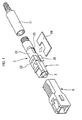
- Fig. 1 is an exploded perspective view showing a schematic structure according to an embodiment of the optical connector in accordance with the invention
- Fig. 2 is a cross-sectional view showing an operation for opening/closing a positioning mechanism of the optical connector illustrated in Fig. 1 by inserting a wedge
- Fig. 3 is a longitudinal sectional view showing a connector plug assembly illustrated in Fig. 1
- Fig. 4 is an enlarged view showing an A portion in Fig. 3
- Fig. 5 is an explanatory view showing a procedure for a method of assembling a site optical fiber into the optical connector illustrated in Fig. 1 .
- An optical connector 1 is an SC connector to be assembled into a site optical fiber and is constituted by a plug housing 7 for accommodating a ferrule 3 and a positioning mechanism 5 to be coupled to a rear end of the ferrule 3, thereby forming a connector plug assembly, a connector knob 9 put on and attached to the plug housing 7 from a forward part, and a boot 11 put on and attached to a rear end of the plug housing 7 as shown in Figs. 1 to 3 .
- a fiber inserting hole 15 (see Fig. 4 ) for inserting a site optical fiber 14 having a coating is formed on a central axis to penetrate the ferrule 3.
- An almost sheet-like protecting member 17 for transmitting a light in a predetermined refractive index is stuck to a tip surface of the ferrule 3 with the fiber inserting hole 15 covered.
- the protecting member 17 has a refractive index which is equal to that of a core of the optical fiber 14.
- the protecting member 17 takes a shape of a sheet having a thickness of 5 to 30 ⁇ m, and an adhesiveness for applying an adhesive material and sticking to the ferrule 3 is given to a surface on a side to come in contact with the ferrule 3.
- An external surface 17a of the protecting member 17 has no adhesiveness and dust sticks thereto with difficulty.
- the positioning mechanism 5 is a so-called splice member and includes a base member 21 provided with a V groove 21a for positioning the optical fiber 14 in such a manner that a center of the optical fiber 14 having a coating is coincident with that of the positioning mechanism 5, a cover member 22 superposed on the base member 21 to press the optical fiber 14 against the V groove 21a, and a clamp member 24 for energizing the base member 21 and the cover member 22 in a bonding direction as shown in Fig. 2 .
- the base member 21 and the cover member 22 in the positioning mechanism 5 can be opened against an energizing force of the clamp member 24 through an insertion of a wedge 26 into a wedge inserting portion 25 formed on a joining surface of both of them as shown in Fig. 2(a) , and the optical fiber 14 is inserted into the V groove 21a and the wedge 26 is then pulled out as shown in Fig. 2(b) so that the optical fiber 14 is interposed and positioned between the base member 21 and the cover member 22 by the energizing force of the clamp member 24.
- a flexure space 41 for causing the inserted optical fiber 14 to have an elastic force toward the protecting member 17 side by accommodating the optical fiber 14 in a flexing state is provided between the rear end of the ferrule 3 and a tip side of the positioning mechanism 5.
- the flexure space 41 is formed by hollowing a tip side of the base member 21 and the cover member 22 which form the positioning mechanism 5.
- the optical fiber 14 inserted through the ferrule 3 and the positioning mechanism 5 is interposed and fixed by the positioning mechanism 5 after an amount of the insertion of the optical fiber 14 into the positioning mechanism 5 is regulated to generate a flexure 43 in the flexure space 41.
- a tip surface of the optical fiber 14 which is positioned is maintained in an abutting state on the protecting member 17 provided on the tip of the ferrule 3 with an elastic force.
- the plug housing 7 is constituted by a front housing 33 having a step-like positioning portion 31 which positions, through a collision, the front end portions of the base member 21 and the cover member 22 which form the positioning mechanism 5, and a rear housing 35 which accommodates the positioning mechanism 5 from a rear end side thereof and is thus coupled to a rear end of the front housing 33.
- the rear housing 35 is coupled to and integrated with the front housing 33 by engaging an engaging projection 35b of an engaging portion 35a extended forward with an engaging portion 3 3 a provided on the front housing 33.
- the rear housing 35 includes a spring member 37 for energizing the positioning mechanism 5 forward to elastically position the front end portions of the base member 21 and the cover member 22 in an abutting state on the positioning portion 31 of the front housing 33.
- the boot 11 put on and attached to the rear part of the rear housing 35 covers a periphery of the optical fiber 14 extended from the positioning mechanism 5 and protects the optical fiber 14 to prevent bending from being suddenly applied to the optical fiber 14.
- the positioning mechanism 5 and the ferrule 3 are elastically supported movably in a rearward direction by means of the spring member 37 accommodated in the rear housing 35. In a connection to a partner optical connector, therefore, the ferrule 3 abutting on the partner optical connector can be moved rearward by an elastic force to relieve a shock.
- the optical connector 1 is assembled in a procedure shown in Figs. 5(a) to 5(d) .
- the positioning mechanism 5 coupled to the rear end of the ferrule 3 is prepared in a state in which it is opened by the insertion of the wedge 26, and the end of the site optical fiber 14 is subjected to a cut processing.
- the optical fiber 14 subjected to the cut processing is inserted through the positioning mechanism 5 and the ferrule 3.
- Fig. 5(a) the positioning mechanism 5 coupled to the rear end of the ferrule 3 is prepared in a state in which it is opened by the insertion of the wedge 26, and the end of the site optical fiber 14 is subjected to a cut processing.
- the optical fiber 14 subjected to the cut processing is inserted through the positioning mechanism 5 and the ferrule 3.
- the amount of the insertion of the optical fiber 14 is regulated in such a manner that the optical fiber 14 inserted through the ferrule 3 generates the flexure 43 in a proper amount in the flexure space 41, and the wedge 26 is then pulled out of the positioning mechanism 5. Consequently, the optical fiber 14 inserted in the ferrule 3 is fixed by the positioning mechanism 5 with the tip coming in elastic contact with the protecting member 17.
- the front housing 33 and the rear housing 35 in the plug housing 7 are put on and attached to the positioning mechanism 5.
- the boot 11 is attached to the rear end of the plug housing 7 and the connector knob 9 is attached to the outer periphery of the plug housing 7, which is not shown.
- the optical connector 1 is completely assembled.
- an end face of the site optical fiber 14 is subjected to a cut processing, and the optical fiber 14 is inserted through the positioning mechanism 5 and the ferrule 3 until the end face abuts on the protecting member 17 with an elastic force, and furthermore, the optical fiber 14 is caused to have the flexure 43 in the flexure space 41 and is then positioned and fixed by the positioning mechanism 5.
- the assembly is completed.
- the built-in optical fiber is omitted, there is not caused a problem, for example, a breakage of the end face of the built-in optical fiber due to the collision of the site optical fiber 14 which is inserted in the ferrule 3.
- the protecting member is provided on the tip surface of the ferrule so that it is not necessary to carry out a polishing processing over the end face of the built-in optical fiber. Therefore, it is also possible to reduce a cost correspondingly. Accordingly, it is possible to reduce a cost for assembling the connector into the site optical fiber 14 more greatly.
- the protecting member 17 provided on the tip surface of the ferrule 3 can easily be attached to the ferrule 3 by giving an adhesiveness to only the ferrule 3 side, and can prevent dust from sticking onto an external surface.
- the protecting member 17 is effective for protecting the tip surface of the optical fiber 14 to abut on the protecting member 17.
- the protecting member 17 has a refractive index which is equal to that of the core of the site optical fiber 14. Therefore, it is possible to reduce a light transmission loss as greatly as possible and to obtain a high return loss.
- the protecting member 17 takes a shape of a sheet having a thickness of 5 to 30 ⁇ m.
- the film thickness of the protecting member 17 is small, thus, it is possible to reduce the light transmission loss as greatly as possible.
- the flexure space 41 for accommodating the optical fiber 14 in a flexing state to cause the optical fiber 14 to have an elastic force turned toward the protecting member 17 side is provided between the rear end of the ferrule 3 and the tip side of the positioning mechanism 5.
- the end of the site optical fiber 14 is subjected to the cut processing, the optical fiber 14 subjected to the cut processing is exactly inserted through the positioning mechanism 5 and the ferrule 3 in the optical connector 1 without the coating peeled and the tip of the optical fiber 14 is thus caused to come in elastic contact with the protecting member 17, and the optical fiber 14 is fixed by the positioning mechanism 5 in this state. Consequently, it is possible to bring a state in which the optical connector 1 is assembled into the optical fiber 14.
- the ferrule 3 and the positioning mechanism 5 are separate members. However, it is also possible to employ a structure in which the ferrule 3 and the positioning mechanism 5 are fabricated by integral molding. With the integral structure, thus, it is possible to reduce the number of the components constituting the optical connector 1, thereby promoting an enhancement in an assembling property and a reduction in a cost.
Applications Claiming Priority (2)
| Application Number | Priority Date | Filing Date | Title |
|---|---|---|---|
| JP2007137201A JP2008292710A (ja) | 2007-05-23 | 2007-05-23 | 光コネクタ及びその組立方法 |
| PCT/JP2008/058680 WO2008143038A1 (ja) | 2007-05-23 | 2008-05-09 | 光コネクタ及びその組立方法 |
Publications (2)
| Publication Number | Publication Date |
|---|---|
| EP2149805A1 true EP2149805A1 (de) | 2010-02-03 |
| EP2149805A4 EP2149805A4 (de) | 2013-05-01 |
Family
ID=40031748
Family Applications (1)
| Application Number | Title | Priority Date | Filing Date |
|---|---|---|---|
| EP08752563.0A Withdrawn EP2149805A4 (de) | 2007-05-23 | 2008-05-09 | Optischer steckverbinder und verfahren zu seiner montage |
Country Status (6)
| Country | Link |
|---|---|
| US (1) | US8511910B2 (de) |
| EP (1) | EP2149805A4 (de) |
| JP (1) | JP2008292710A (de) |
| CN (1) | CN101681000A (de) |
| TW (1) | TW200918976A (de) |
| WO (1) | WO2008143038A1 (de) |
Families Citing this family (17)
| Publication number | Priority date | Publication date | Assignee | Title |
|---|---|---|---|---|
| JP2008292710A (ja) * | 2007-05-23 | 2008-12-04 | Sumitomo Electric Ind Ltd | 光コネクタ及びその組立方法 |
| EP2299305A4 (de) | 2008-06-13 | 2017-11-15 | Fujikura, Ltd. | Verbindungsverfahren, verbindungswerkzeug und verbidungslehre für glasfaser |
| JP5027789B2 (ja) * | 2008-12-03 | 2012-09-19 | 住友電気工業株式会社 | 光コネクタの組立方法及び光コネクタ |
| JP5027788B2 (ja) * | 2008-12-03 | 2012-09-19 | 住友電気工業株式会社 | 光コネクタの組立方法及び光コネクタ |
| JP5199946B2 (ja) * | 2009-05-19 | 2013-05-15 | 住友電気工業株式会社 | 光コネクタ及びその組立方法 |
| JP5182955B2 (ja) * | 2009-08-10 | 2013-04-17 | 日本電信電話株式会社 | 光ファイバの調心構造及びこれを用いた光コネクタ並びに光ファイバの調心方法 |
| US9158075B2 (en) * | 2009-10-15 | 2015-10-13 | Corning Incorporated | Fiber optic connectors and structures for large core optical fibers and methods for making the same |
| US8998502B2 (en) * | 2010-09-03 | 2015-04-07 | Corning Incorporated | Fiber optic connectors and ferrules and methods for using the same |
| JP2013210418A (ja) * | 2012-03-30 | 2013-10-10 | Furukawa Electric Co Ltd:The | 光コネクタ、光コネクタ用雄型コネクタハウジング、及び光コネクタ用雌型コネクタハウジング |
| RU2606700C2 (ru) * | 2012-04-27 | 2017-01-10 | 3М Инновейтив Пропертиз Компани | Волоконно-оптический коннектор |
| CN102928923B (zh) * | 2012-11-01 | 2014-01-29 | 南京普天天纪楼宇智能有限公司 | 一种热熔型现场组装式光纤连接器 |
| JP5483502B2 (ja) * | 2012-12-13 | 2014-05-07 | 日本電信電話株式会社 | 光ファイバの調心構造及びこれを用いた光コネクタ並びに光ファイバの調心方法 |
| CN103823278B (zh) * | 2014-02-20 | 2016-05-04 | 深圳日海通讯技术股份有限公司 | 一种光纤连接器及其制造方法 |
| DE102014105523A1 (de) * | 2014-04-17 | 2015-10-22 | Reichle & De-Massari Ag | Steckverbindervorrichtung |
| DE102014105524A1 (de) * | 2014-04-17 | 2015-10-22 | Reichle & De-Massari Ag | Steckverbindervorrichtung |
| US9784924B2 (en) * | 2014-06-30 | 2017-10-10 | Ultra Communications, Inc. | Fiber optic end-face transparent protector |
| JP7213369B2 (ja) * | 2019-03-26 | 2023-01-26 | スリーエム イノベイティブ プロパティズ カンパニー | 光コネクタアセンブリ |
Citations (2)
| Publication number | Priority date | Publication date | Assignee | Title |
|---|---|---|---|---|
| EP0195355A2 (de) * | 1985-03-12 | 1986-09-24 | Toray Silicone Company Limited | Brechungsindexangepasste elastische Zusammensetzung zur Verbindung optischer Übertragungsfasern |
| JP2007108358A (ja) * | 2005-10-12 | 2007-04-26 | Fujikura Ltd | 単心光コネクタ及び多心光コネクタ |
Family Cites Families (30)
| Publication number | Priority date | Publication date | Assignee | Title |
|---|---|---|---|---|
| US3871744A (en) * | 1974-08-19 | 1975-03-18 | Gte Laboratories Inc | Optical fiber connector |
| US4147402A (en) * | 1977-06-30 | 1979-04-03 | International Standard Electric Corporation | Process for manufacturing an optical fiber termination |
| US4373777A (en) * | 1980-08-11 | 1983-02-15 | International Telephone And Telegraph Corporation | Connector and cable assembly |
| US4436366A (en) * | 1981-02-17 | 1984-03-13 | E. I. Du Pont De Nemours And Company | End capping an optical fiber |
| US4518220A (en) * | 1983-03-30 | 1985-05-21 | Gte Products Corporation | Fiber optic drawer connector assembly |
| US4770488A (en) * | 1985-12-18 | 1988-09-13 | Gte Service Corporation | Fiber optical connector with lens |
| JPS63141906A (ja) | 1986-12-03 | 1988-06-14 | G C Dental Ind Corp | 歯科鋳造用埋没材 |
| JPS63141906U (de) * | 1987-03-10 | 1988-09-19 | ||
| US5067226A (en) * | 1988-06-20 | 1991-11-26 | Amp Incorporated | Method of assembling an optical fiber by applying pressure to abutting optical faces |
| JP2676705B2 (ja) * | 1989-12-05 | 1997-11-17 | 株式会社フジクラ | 光ファイバコネクタ |
| JPH06511565A (ja) * | 1991-05-09 | 1994-12-22 | アイテイーテイー・インダストリーズ・インコーポレーテッド | 接触する先端部を有する光ファイバコネクタ |
| US5434940A (en) * | 1994-03-24 | 1995-07-18 | The Whitaker Corporation | Active fiber needle |
| US6409394B1 (en) * | 2000-03-21 | 2002-06-25 | Sumitomo Electric Industries, Ltd. | Optical connector |
| US6565265B2 (en) * | 2000-03-23 | 2003-05-20 | Sumitomo Electric Industries, Ltd. | Optical connector and method of assembling optical connector |
| JP2002031745A (ja) * | 2000-07-19 | 2002-01-31 | Nippon Telegr & Teleph Corp <Ntt> | 光コネクタプラグ及びこれを備えた装置の光接続部構造 |
| AU2002243312A1 (en) * | 2000-10-25 | 2002-07-24 | Tyco Electronics | Optical ferrule-less connector |
| JP2005245753A (ja) | 2004-03-04 | 2005-09-15 | Sharp Corp | 食器洗い乾燥機 |
| JP2005345753A (ja) | 2004-06-03 | 2005-12-15 | Sumitomo Electric Ind Ltd | 光コネクタ及びその組み立て方法 |
| JP4821209B2 (ja) * | 2005-04-14 | 2011-11-24 | 住友電気工業株式会社 | 光コネクタ及び光コネクタの組立方法 |
| JP2007137201A (ja) | 2005-11-16 | 2007-06-07 | Aisin Seiki Co Ltd | 車両用サンバイザー装置 |
| US7534051B2 (en) * | 2006-04-12 | 2009-05-19 | Sumitomo Electric Industries, Ltd. | Optical fiber connector, optical fiber connecting method, and connector converter |
| US7572064B2 (en) * | 2006-07-24 | 2009-08-11 | Corning Cable Systems Llc | Optical fiber mechanical splice connector |
| EP1903361B1 (de) * | 2006-09-22 | 2020-04-01 | Nippon Electric Glass Co., Ltd. | Optisches Element und lichtemittierende Vorrichtung unter Verwendung desselben |
| US7452138B2 (en) * | 2006-09-27 | 2008-11-18 | Fujikura Ltd. | Optical connector |
| US7628549B2 (en) * | 2007-01-25 | 2009-12-08 | Fujikura Ltd. | Optical connector |
| JP5034650B2 (ja) * | 2007-04-23 | 2012-09-26 | 住友電気工業株式会社 | 光ファイバ接続器及び光ケーブル |
| JP2008292710A (ja) * | 2007-05-23 | 2008-12-04 | Sumitomo Electric Ind Ltd | 光コネクタ及びその組立方法 |
| JP2008292708A (ja) * | 2007-05-23 | 2008-12-04 | Sumitomo Electric Ind Ltd | 光コネクタ及びその組立方法 |
| JP5297025B2 (ja) * | 2007-11-20 | 2013-09-25 | 住友電気工業株式会社 | 光コネクタ及び該光コネクタの被覆付き光ファイバへの装着方法 |
| JP4714207B2 (ja) * | 2007-11-21 | 2011-06-29 | 住友電気工業株式会社 | 光接続部材およびその装着方法 |
-
2007
- 2007-05-23 JP JP2007137201A patent/JP2008292710A/ja active Pending
-
2008
- 2008-05-09 EP EP08752563.0A patent/EP2149805A4/de not_active Withdrawn
- 2008-05-09 WO PCT/JP2008/058680 patent/WO2008143038A1/ja active Application Filing
- 2008-05-09 US US12/601,375 patent/US8511910B2/en not_active Expired - Fee Related
- 2008-05-09 CN CN200880017014A patent/CN101681000A/zh active Pending
- 2008-05-22 TW TW097118949A patent/TW200918976A/zh unknown
Patent Citations (2)
| Publication number | Priority date | Publication date | Assignee | Title |
|---|---|---|---|---|
| EP0195355A2 (de) * | 1985-03-12 | 1986-09-24 | Toray Silicone Company Limited | Brechungsindexangepasste elastische Zusammensetzung zur Verbindung optischer Übertragungsfasern |
| JP2007108358A (ja) * | 2005-10-12 | 2007-04-26 | Fujikura Ltd | 単心光コネクタ及び多心光コネクタ |
Non-Patent Citations (1)
| Title |
|---|
| See also references of WO2008143038A1 * |
Also Published As
| Publication number | Publication date |
|---|---|
| JP2008292710A (ja) | 2008-12-04 |
| US20100290740A1 (en) | 2010-11-18 |
| CN101681000A (zh) | 2010-03-24 |
| EP2149805A4 (de) | 2013-05-01 |
| TW200918976A (en) | 2009-05-01 |
| WO2008143038A1 (ja) | 2008-11-27 |
| US8511910B2 (en) | 2013-08-20 |
Similar Documents
| Publication | Publication Date | Title |
|---|---|---|
| EP2149805A1 (de) | Optischer steckverbinder und verfahren zu seiner montage | |
| JP5184865B2 (ja) | 光コネクタ | |
| US8317406B2 (en) | Optical connector | |
| WO2006019161A1 (ja) | 光コネクタ、及び光コネクタの組立方法 | |
| TWI439745B (zh) | 光連接部件及其裝設方法 | |
| JP3602339B2 (ja) | 光コネクタ | |
| EP2149806A1 (de) | Optischer steckverbinder und verfahren zu seiner montage | |
| US9235009B2 (en) | Optical connector and method of preventing protection tube from coming off from optical connector | |
| JP4191168B2 (ja) | メカニカル接続型光コネクタ | |
| JP4969976B2 (ja) | 光ファイバ心線への光コネクタ取付方法、光ファイバ心線保護チューブ及びそれに用いられる心線仮固定具 | |
| JP5898510B2 (ja) | 光コネクタ | |
| KR20020021112A (ko) | 광커넥터 플러그, 그 제조방법 및 조립공구 | |
| US8388237B2 (en) | Optical connector and method of assembling optical connector | |
| JP3504567B2 (ja) | 光コネクタ | |
| JP2009139837A (ja) | 光コネクタ | |
| JP2005345753A (ja) | 光コネクタ及びその組み立て方法 | |
| JP4477409B2 (ja) | メカニカル接続型光コネクタ。 | |
| JP2005121988A (ja) | 光ファイバ接続器、光ファイバ接続方法及びコネクタ変換器 | |
| JP2001051159A (ja) | 光コネクタプラグ、その製造方法および組立工具 | |
| JP2013015787A (ja) | 光コネクタおよびその組立方法 | |
| JP3501440B2 (ja) | 光コネクタ | |
| JP4192749B2 (ja) | 光ファイバ接続器、光ファイバ接続方法及び光モジュール | |
| JP2008262245A (ja) | 光コネクタ組立工具 | |
| JP2000338367A (ja) | 光コネクタおよび光コネクタ接続方式 | |
| JP5324895B2 (ja) | 光コネクタプラグ |
Legal Events
| Date | Code | Title | Description |
|---|---|---|---|
| PUAI | Public reference made under article 153(3) epc to a published international application that has entered the european phase |
Free format text: ORIGINAL CODE: 0009012 |
|
| 17P | Request for examination filed |
Effective date: 20091123 |
|
| AK | Designated contracting states |
Kind code of ref document: A1 Designated state(s): AT BE BG CH CY CZ DE DK EE ES FI FR GB GR HR HU IE IS IT LI LT LU LV MC MT NL NO PL PT RO SE SI SK TR |
|
| AX | Request for extension of the european patent |
Extension state: AL BA MK RS |
|
| DAX | Request for extension of the european patent (deleted) | ||
| A4 | Supplementary search report drawn up and despatched |
Effective date: 20130402 |
|
| RIC1 | Information provided on ipc code assigned before grant |
Ipc: G02B 6/38 20060101AFI20130325BHEP |
|
| STAA | Information on the status of an ep patent application or granted ep patent |
Free format text: STATUS: THE APPLICATION HAS BEEN WITHDRAWN |
|
| 18W | Application withdrawn |
Effective date: 20130529 |