EP2140212B1 - Kippanordnung für nachlauf-sonnenkollektoranordnung - Google Patents
Kippanordnung für nachlauf-sonnenkollektoranordnung Download PDFInfo
- Publication number
- EP2140212B1 EP2140212B1 EP08728137.4A EP08728137A EP2140212B1 EP 2140212 B1 EP2140212 B1 EP 2140212B1 EP 08728137 A EP08728137 A EP 08728137A EP 2140212 B1 EP2140212 B1 EP 2140212B1
- Authority
- EP
- European Patent Office
- Prior art keywords
- drive
- assembly
- solar collector
- drive arm
- tilt
- Prior art date
- Legal status (The legal status is an assumption and is not a legal conclusion. Google has not performed a legal analysis and makes no representation as to the accuracy of the status listed.)
- Not-in-force
Links
- 230000000712 assembly Effects 0.000 claims description 58
- 238000000429 assembly Methods 0.000 claims description 58
- 230000033001 locomotion Effects 0.000 claims description 24
- 230000008901 benefit Effects 0.000 description 9
- 238000009434 installation Methods 0.000 description 7
- 238000000034 method Methods 0.000 description 5
- 238000003491 array Methods 0.000 description 3
- 238000009412 basement excavation Methods 0.000 description 3
- 238000002360 preparation method Methods 0.000 description 3
- 239000000853 adhesive Substances 0.000 description 2
- 230000001070 adhesive effect Effects 0.000 description 2
- 238000010276 construction Methods 0.000 description 2
- 230000007246 mechanism Effects 0.000 description 2
- 230000009467 reduction Effects 0.000 description 2
- 230000000284 resting effect Effects 0.000 description 2
- 229910000831 Steel Inorganic materials 0.000 description 1
- 230000001413 cellular effect Effects 0.000 description 1
- 230000008878 coupling Effects 0.000 description 1
- 238000010168 coupling process Methods 0.000 description 1
- 238000005859 coupling reaction Methods 0.000 description 1
- 238000011161 development Methods 0.000 description 1
- 230000000694 effects Effects 0.000 description 1
- 238000010438 heat treatment Methods 0.000 description 1
- 230000002452 interceptive effect Effects 0.000 description 1
- 238000012423 maintenance Methods 0.000 description 1
- 238000004519 manufacturing process Methods 0.000 description 1
- 239000000463 material Substances 0.000 description 1
- 238000012986 modification Methods 0.000 description 1
- 230000004048 modification Effects 0.000 description 1
- 230000002093 peripheral effect Effects 0.000 description 1
- 238000011160 research Methods 0.000 description 1
- 238000012552 review Methods 0.000 description 1
- 239000011435 rock Substances 0.000 description 1
- 239000002689 soil Substances 0.000 description 1
- 239000007787 solid Substances 0.000 description 1
- 239000010959 steel Substances 0.000 description 1
- 238000012546 transfer Methods 0.000 description 1
Images


Classifications
-
- F—MECHANICAL ENGINEERING; LIGHTING; HEATING; WEAPONS; BLASTING
- F24—HEATING; RANGES; VENTILATING
- F24S—SOLAR HEAT COLLECTORS; SOLAR HEAT SYSTEMS
- F24S30/00—Arrangements for moving or orienting solar heat collector modules
- F24S30/40—Arrangements for moving or orienting solar heat collector modules for rotary movement
- F24S30/42—Arrangements for moving or orienting solar heat collector modules for rotary movement with only one rotation axis
- F24S30/428—Arrangements for moving or orienting solar heat collector modules for rotary movement with only one rotation axis with inclined axis
-
- F—MECHANICAL ENGINEERING; LIGHTING; HEATING; WEAPONS; BLASTING
- F24—HEATING; RANGES; VENTILATING
- F24S—SOLAR HEAT COLLECTORS; SOLAR HEAT SYSTEMS
- F24S25/00—Arrangement of stationary mountings or supports for solar heat collector modules
- F24S25/10—Arrangement of stationary mountings or supports for solar heat collector modules extending in directions away from a supporting surface
- F24S25/11—Arrangement of stationary mountings or supports for solar heat collector modules extending in directions away from a supporting surface using shaped bodies, e.g. concrete elements, foamed elements or moulded box-like elements
-
- F—MECHANICAL ENGINEERING; LIGHTING; HEATING; WEAPONS; BLASTING
- F24—HEATING; RANGES; VENTILATING
- F24S—SOLAR HEAT COLLECTORS; SOLAR HEAT SYSTEMS
- F24S25/00—Arrangement of stationary mountings or supports for solar heat collector modules
- F24S25/60—Fixation means, e.g. fasteners, specially adapted for supporting solar heat collector modules
- F24S25/61—Fixation means, e.g. fasteners, specially adapted for supporting solar heat collector modules for fixing to the ground or to building structures
- F24S25/617—Elements driven into the ground, e.g. anchor-piles; Foundations for supporting elements; Connectors for connecting supporting structures to the ground or to flat horizontal surfaces
-
- H—ELECTRICITY
- H02—GENERATION; CONVERSION OR DISTRIBUTION OF ELECTRIC POWER
- H02S—GENERATION OF ELECTRIC POWER BY CONVERSION OF INFRARED RADIATION, VISIBLE LIGHT OR ULTRAVIOLET LIGHT, e.g. USING PHOTOVOLTAIC [PV] MODULES
- H02S20/00—Supporting structures for PV modules
-
- H—ELECTRICITY
- H02—GENERATION; CONVERSION OR DISTRIBUTION OF ELECTRIC POWER
- H02S—GENERATION OF ELECTRIC POWER BY CONVERSION OF INFRARED RADIATION, VISIBLE LIGHT OR ULTRAVIOLET LIGHT, e.g. USING PHOTOVOLTAIC [PV] MODULES
- H02S20/00—Supporting structures for PV modules
- H02S20/30—Supporting structures being movable or adjustable, e.g. for angle adjustment
- H02S20/32—Supporting structures being movable or adjustable, e.g. for angle adjustment specially adapted for solar tracking
-
- F—MECHANICAL ENGINEERING; LIGHTING; HEATING; WEAPONS; BLASTING
- F24—HEATING; RANGES; VENTILATING
- F24S—SOLAR HEAT COLLECTORS; SOLAR HEAT SYSTEMS
- F24S25/00—Arrangement of stationary mountings or supports for solar heat collector modules
- F24S2025/01—Special support components; Methods of use
- F24S2025/012—Foldable support elements
-
- F—MECHANICAL ENGINEERING; LIGHTING; HEATING; WEAPONS; BLASTING
- F24—HEATING; RANGES; VENTILATING
- F24S—SOLAR HEAT COLLECTORS; SOLAR HEAT SYSTEMS
- F24S25/00—Arrangement of stationary mountings or supports for solar heat collector modules
- F24S2025/01—Special support components; Methods of use
- F24S2025/013—Stackable support elements
-
- F—MECHANICAL ENGINEERING; LIGHTING; HEATING; WEAPONS; BLASTING
- F24—HEATING; RANGES; VENTILATING
- F24S—SOLAR HEAT COLLECTORS; SOLAR HEAT SYSTEMS
- F24S30/00—Arrangements for moving or orienting solar heat collector modules
- F24S2030/10—Special components
- F24S2030/13—Transmissions
- F24S2030/131—Transmissions in the form of articulated bars
-
- F—MECHANICAL ENGINEERING; LIGHTING; HEATING; WEAPONS; BLASTING
- F24—HEATING; RANGES; VENTILATING
- F24S—SOLAR HEAT COLLECTORS; SOLAR HEAT SYSTEMS
- F24S30/00—Arrangements for moving or orienting solar heat collector modules
- F24S2030/10—Special components
- F24S2030/13—Transmissions
- F24S2030/136—Transmissions for moving several solar collectors by common transmission elements
-
- F—MECHANICAL ENGINEERING; LIGHTING; HEATING; WEAPONS; BLASTING
- F24—HEATING; RANGES; VENTILATING
- F24S—SOLAR HEAT COLLECTORS; SOLAR HEAT SYSTEMS
- F24S30/00—Arrangements for moving or orienting solar heat collector modules
- F24S2030/10—Special components
- F24S2030/16—Hinged elements; Pin connections
-
- H—ELECTRICITY
- H02—GENERATION; CONVERSION OR DISTRIBUTION OF ELECTRIC POWER
- H02S—GENERATION OF ELECTRIC POWER BY CONVERSION OF INFRARED RADIATION, VISIBLE LIGHT OR ULTRAVIOLET LIGHT, e.g. USING PHOTOVOLTAIC [PV] MODULES
- H02S10/00—PV power plants; Combinations of PV energy systems with other systems for the generation of electric power
- H02S10/30—Thermophotovoltaic systems
-
- H—ELECTRICITY
- H02—GENERATION; CONVERSION OR DISTRIBUTION OF ELECTRIC POWER
- H02S—GENERATION OF ELECTRIC POWER BY CONVERSION OF INFRARED RADIATION, VISIBLE LIGHT OR ULTRAVIOLET LIGHT, e.g. USING PHOTOVOLTAIC [PV] MODULES
- H02S20/00—Supporting structures for PV modules
- H02S20/10—Supporting structures directly fixed to the ground
-
- Y—GENERAL TAGGING OF NEW TECHNOLOGICAL DEVELOPMENTS; GENERAL TAGGING OF CROSS-SECTIONAL TECHNOLOGIES SPANNING OVER SEVERAL SECTIONS OF THE IPC; TECHNICAL SUBJECTS COVERED BY FORMER USPC CROSS-REFERENCE ART COLLECTIONS [XRACs] AND DIGESTS
- Y02—TECHNOLOGIES OR APPLICATIONS FOR MITIGATION OR ADAPTATION AGAINST CLIMATE CHANGE
- Y02E—REDUCTION OF GREENHOUSE GAS [GHG] EMISSIONS, RELATED TO ENERGY GENERATION, TRANSMISSION OR DISTRIBUTION
- Y02E10/00—Energy generation through renewable energy sources
- Y02E10/40—Solar thermal energy, e.g. solar towers
- Y02E10/47—Mountings or tracking
-
- Y—GENERAL TAGGING OF NEW TECHNOLOGICAL DEVELOPMENTS; GENERAL TAGGING OF CROSS-SECTIONAL TECHNOLOGIES SPANNING OVER SEVERAL SECTIONS OF THE IPC; TECHNICAL SUBJECTS COVERED BY FORMER USPC CROSS-REFERENCE ART COLLECTIONS [XRACs] AND DIGESTS
- Y02—TECHNOLOGIES OR APPLICATIONS FOR MITIGATION OR ADAPTATION AGAINST CLIMATE CHANGE
- Y02E—REDUCTION OF GREENHOUSE GAS [GHG] EMISSIONS, RELATED TO ENERGY GENERATION, TRANSMISSION OR DISTRIBUTION
- Y02E10/00—Energy generation through renewable energy sources
- Y02E10/50—Photovoltaic [PV] energy
-
- Y—GENERAL TAGGING OF NEW TECHNOLOGICAL DEVELOPMENTS; GENERAL TAGGING OF CROSS-SECTIONAL TECHNOLOGIES SPANNING OVER SEVERAL SECTIONS OF THE IPC; TECHNICAL SUBJECTS COVERED BY FORMER USPC CROSS-REFERENCE ART COLLECTIONS [XRACs] AND DIGESTS
- Y10—TECHNICAL SUBJECTS COVERED BY FORMER USPC
- Y10T—TECHNICAL SUBJECTS COVERED BY FORMER US CLASSIFICATION
- Y10T29/00—Metal working
- Y10T29/49—Method of mechanical manufacture
- Y10T29/4935—Heat exchanger or boiler making
- Y10T29/49355—Solar energy device making
Definitions
- This invention relates to solar energy collection, and in particular to an arrangement for driving a row of solar collector assemblies to track the motion of the sun relative to the earth.
- the invention applies to solar collectors in which the solar collector modules include arrays of photovoltaic cells for generating electrical power, but the same principles can be applied also to arrangements for solar heating, for example.
- Photovoltaic arrays are used for a variety of purposes, including as a utility interactive power system, as a power supply for a remote or unmanned site, a cellular phone switch-site power supply, or a village power supply. These arrays can have a capacity from a few kilowatts to a hundred kilowatts or more, and are typically installed where there is a reasonably flat area with exposure to the sun for significant portions of the day.
- these solar collector assemblies have their solar collector modules, typically photovoltaic modules, supported on a frame.
- the frame commonly includes a frame member, sometimes referred to as a torque tube or torque member, which serves as an axis.
- a tracker drive system also called a tilt assembly, may be used to rotate or rock the solar collector assemblies of the one or more rows of solar collector assemblies about their tilt axes to keep the photovoltaic modules as square to the sun as possible.
- the rows are arranged with the tilt axes of the solar collector assemblies disposed in a north-south direction, and the tilt assemblies gradually rotate the one or more rows of solar collector assemblies throughout the day from an east-facing direction in the morning to a west-facing direction in the afternoon.
- the solar collector assemblies are brought back to the east-facing orientation for the next day.
- each row of panels is affixed to a horizontal pivot shaft that is supported on two or more support piers on which the pivot shaft is journaled.
- a drive mechanism is mounted on one of the piers, and pushes against the solar panel at some point that is displaced from the shaft.
- the drive is of the screw type, and as a drive motor rotates, a shaft retracts or extends to rotate the row of panels in one direction or the other.
- each row of panels has its own respective drive mechanism.
- Other designs such as that shown in US patent number 6,058,930 , employ a single actuator to control multiple rows of solar panels.
- WO 2004/083741 A2 relates to a tracking solar collector assembly having a plurality of supports and support structures.
- a tilt assembly is used with a solar collector assembly of the type comprising a frame, supporting a solar collector, for movement about a tilt axis by pivoting a drive element between first and second orientations.
- the tilt assembly comprises a drive element coupler connected to the drive element at a position along the drive element spaced apart from the tilt axis by a first distance.
- the tilt assembly also comprises a driver, the driver comprising a drive frame, a drive arm and a drive arm driver.
- the drive arm is mounted to the drive frame for pivotal movement about a drive arm axis.
- the drive arm is pivotal between third and fourth orientations.
- the drive arm has an inner portion extending from the drive frame and an outer portion drivingly connected to the drive element coupler at a drive position along the drive arm.
- the drive position is spaced apart from the drive arm axis by a second distance.
- the drive arm driver is drivingly coupled to the drive arm for movement of the drive arm between the third and fourth orientations.
- the drive frame is constructed so that the drive element coupler can pass beneath a portion of the drive frame as the drive arm pivots between the third and fourth orientations.
- the driver further comprises a drive arm support pivotally mounted to the drive frame for pivotal movement about the drive arm axis, the drive arm being mounted to the drive arm support.
- the drive arm axis is orientable to be substantially parallel to the tilt axis.
- the driver is configured such that movement of the drive arm between the third and fourth orientations substantially mimics movement of the drive element between the first and second orientations.
- first and second of the drive element couplers extend in substantially opposite directions from the outer portion of the drive arm, whereby the assembly can be used between adjacent solar collector assemblies in a row of solar collector assemblies.
- One of the advantages accruing from some examples of the invention is that the movement of the drive arm of the tilt assembly mimics the movement of the drive element of the solar collector assembly for improved drive efficiency.
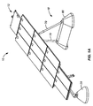
- Fig. 1 illustrates a solar collector assembly 10 including broadly a solar collector module assembly 12 mounted above a support surface 14, typically the ground, by a first support 16, sometimes referred to as south side support 16, and by a second support 18, sometimes referred to as north side support 18.
- Solar collector module assembly 12 includes a frame 20 supporting a number of solar collector modules 22.
- frame 20 includes a frame member 24, sometimes referred to as torque member 24, supporting transversely oriented rails 26.
- Solar collector modules 22 are secured to rails 26 by clips 27 (see Figs. 6 and 7A ) or other mounting structure appropriate to the construction of the solar collector modules.
- clips 27 see Figs. 6 and 7A
- An example of clips suitable for use with solar collector modules 22 having a peripheral frame is disclosed in U.S. Patent Application No. 11/681,972 filed 05 March 2007 , attorney docket number PWRL 1044-2.
- Fig. 5A illustrates an alternative example in which solar collector module 22 is a frameless module secured to rails 26 of frame 20 using an adhesive.
- the use of a frameless solar collector module can provide several advantages, including saving the cost of solar collector module frames, increasing the stack density due to lower overall height, and helping to prevent theft because frameless modules can be adhered to the substructure which makes it difficult to remove the module without damaging it.
- south side support 16 includes a first surface mount 28, sometimes referred to as south base 28, resting on and substantially above support surface 14. In appropriate cases some surface preparation of support surface 14 may be necessary or desirable to provide a stable surface for base 28.
- South base 28 is an anchorless, ballast type base designed to be sufficiently heavy to secure the south end 30 of torque member 24 in place without the need for substantial excavation of the support surface, such as would be necessary if base 28 were buried within the support surface, or the need to otherwise anchor the south base to support surface 14.
- South base 28 is typically made of concrete.
- south base 28 preferably has a weight of at least 680 kg (1500 lbs.)
- Torque member 24 is pivotally secured to south base 28 by a south side joint 34.
- South side joint 34 includes a south bearing assembly 36 having an inner bearing member 38 affixed to south end 30 of torque member 24 and an outer bearing member 40 rotatable about inner bearing member 38. This permits torque member 24 to rotate or pivot about a tilt axis 42 defined by the torque member.
- South side joint 34 also includes a south pivot mount 44 securing outer bearing member 40 of south bearing assembly 36 to south base 28 for pivotal movement about a generally horizontal south pivot axis 46. This permits tilt angle 32 to be changed.
- the orientation of south pivot mount 44 relative to south base 28 can also be adjusted about a vertical axis.
- the ability to adjust the orientation of south pivot mount and the ability of torque member 24 to pivot about tilt axis 42 and about south pivot axis 46 helps to accommodate unevenness in support surface 14 thereby helping to eliminate extensive preparation of support surface 14 prior to installation.
- north side support 18 includes second surface mounts 66, sometimes referred to as north bases 66, resting on support surface 14.
- North side support 18 includes a support strut 70 extending from each north base 66 and pivotally secured to north end 68 of torque member 24 by a north bearing assembly 72.
- north bases 66 are anchorless, ballast type bases designed to be sufficiently heavy to secure the north end 68 of torque member 24, and therefore solar collector module assembly 12, against wind and other forces without need to excavate or otherwise anchor the north bases to support surface 14.
- North base 66 is typically made of concrete.
- each north base 66 may have a weight of at least 2270 kg (5000 lbs.).
- north base 66 can function as a shared, unitary north base when used between adjacent solar collector assemblies 10 in a row 90 of assemblies 10.
- the north base 66 between assembly 10A and assembly 10B and between assembly 10B and assembly 10C are shared, unitary north bases. This is important because loads, in particular wind loads, on assemblies 10 are not the same and are typically constantly changing. Therefore, loads, in particular lateral loads, exerted on assemblies 10 in the same row 90 can be distributed among the other assemblies in the row through north bases 66. Therefore, the total weight of all of the north bases 10 in row 90 can be less than if north bases were not shared between adjacent solar collector assemblies 10 while making the possibility of overturning solar collector assemblies 10 highly unlikely.
- each north base 66 would be used with a single solar collector module assembly 12; see Fig. 1A .
- a combination of the two can be used in a single row 90 with only some of solar collector assemblies 10 sharing a north base 66.
- Each north bearing assembly 72 is similar to south bearing assembly 36 and includes an inner bearing member 74 affixed to torque member 24 and an outer bearing member 76 rotatably mounted over inner bearing member 74 so to be free to pivot about tilt axis 42.
- the upper end of 78 of each support strut 70 is pivotally mounted to outer bearing member 76 by a clevis-type strut mount 80 so that support strut 70 can pivot about a strut mount axis 82.
- the lower end 84 of support strut 70 see Fig. 4 , is pivotally mounted to north base 66 by a north pivot mount 86.
- North pivot mount 86 is substantially the same as south pivot mount 44 and permits support strut 70 to pivot about a generally horizontal axis corresponding to south pivot axis 46. In addition, north pivot mount 86 can be rotated about a generally vertical axis to aid securing support strut 70 to torque member 24 and north base 66. Support struts 70 are also variable length, telescoping struts. The pivotal connections between support strut 70 and torque member 24, the pivotal connections between support strut 70 and north base 66, and the use of the variable length, telescoping struts 70 enhances the ease of installation of solar collector assembly 10 because exact placement of north bases 66 is not required nor must support surface 14 be extensively graded or otherwise prepared to accept the north bases. The ability to place north and south bases 66, 28 without substantial excavation, that is with only that excavation required to provide a stable support surface for the ballast-type north and south bases, provides a significant cost advantage during installation.
- FIG. 1 solar collector module assembly 12 is pivoted about tilt axis 42, thus allowing the assembly to follow the movement of the sun during the day, by a tilt assembly.
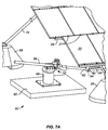
- Figs. 7, 7A and 7B show one example of a tilt assembly 50.
- Tilt assembly 50 includes a driver 52 connected by a drive rod 56 to a torque arm type of drive element 54 extending from torque member 24.
- the inner end 58 of drive element 54 is secured to torque member 24 and extends from the torque member generally perpendicular to a plane defined by solar collector modules 22.
- Drive element 54 includes a clevis-type outer end 60 which receives the clevis-type distal end 62 of drive rod 56 with ends 60, 62 pivotally secured to one another by a pivot element 64, typically a round pin secured by two roll pins.
- Driver 52 causes drive rod 56 to move in a generally linear, generally horizontal fashion; this movement causes outer end 60 of drive element 54 to rotate about tilt axis 42 thus allowing solar collector modules 22 to generally follow the sun.
- Driver 52 is mounted to a footing or foundation 65 which, like south base 28 and north base 66, is typically concrete and is heavy enough not to require burying within the ground. As shown in Fig. 7B , driver 52 is oriented at an angle 69 equal to tilt angle 32 to best accommodate the motion of outer end 60 of drive element 54. Therefore, it is typically desired that foundation 65 be generally horizontal. However, the need for foundation 65 to be generally horizontal can be eliminated by constructing tilt assembly 50 in a manner to eliminate this requirement. For example, the angular orientation between driver 52 and foundation 65 can be made to be adjustable.
- Figs. 19 , 20 and 21 illustrate a tilt assembly 402 comprising a driver 400 and drive element couplers 92.
- Driver 400 is connected to and drives drive element couplers 92.
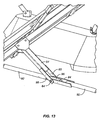
- Drive element couplers 92 extend to drive elements 54, see Fig. 13 , of the solar collector assembly 10 on either side of tilt assembly 402.
- Driver 400 includes a drive frame 406 including a base 408 adapted to be secured an appropriate foundation or other support, not shown.
- the foundation could be an aboveground structure or a fully or partially buried structure.
- base 408 could be bolted, welded or otherwise secured to a large, heavy steel plate with, or without, rods or spikes driven into the earth.
- Other examples for the foundation include a screw-in foundation, a vibration or pressure (or both) driven tube or tubes, and a ballasted vessel filled with (typically local) soil or gravel.
- Drive frame 406 also includes a generally vertical post 410 and a transversely extending member 412 extending from the upper end of post 410 to create a generally L-shaped structure.
- Member 412 extends upwardly and outwardly at an angle to the horizontal generally equal to the inclination of tilt axis 42.
- a pair of support arms 414 extend from either end of member 412.
- a drive arm support 416 is mounted to the distal ends of support arms 414 by bearings 418. This permits drive arm support 416 to rotate about a drive arm axis 420.
- Drive arm axis 420 is arranged to be generally parallel to and generally laterally aligned with pivot axes 42 of the solar collector assemblies 10 on either side of tilt assembly 402.
- Driver 400 also includes a drive arm 422 extending from drive arm support 416 and connected to the clevis-type ends 94 of drive element couplers 92 at a drive position 424.
- the distance from drive position 424 to drive arm support axis 420 is termed second distance 426.
- Second distance 426 is equal to a first distance measured between pivot element 64 and tilt axis 42 passing through the center of torque number 24; see Figs. 7 and 13 .
- Driver 400 also includes a drive arm driver 428 including a motor 430 connected to a drive rod 432 by a gear arrangement 434.
- the gear arrangement 434 typically uses a worm gear reduction to a screw jack; however drive rod 432 can also be driven by a hydraulic pump and jack or other actuation devices.
- the configuration of tilt assembly 402, and especially drive frame 406, permits drive element couplers 92 to freely pass beneath a portion of the drive frame.
- Drive frame 406 accomplishes this in a cantilevered fashion using a single post 410; however, drive frame 406 could be otherwise configured, such as with a post 406 on both sides of drive element couplers 92, to provide this feature.
- Driver 400 also includes an enclosure 436 containing an electronic controller used to control the actuation of motor 430 throughout the day.
- Tilt assembly 402 provides several advantages over tilt assembly 50.
- certain forces specifically non-horizontal forces acting on the solar collector module assemblies 12, are exerted by drive elements 54 on torque members 24 of solar collector assemblies 10 and increase towards the end of the row away from tilt assembly 50.
- Drive arm 422 thus mimics the movement of drive elements 54; this effectively eliminates this transfer of an increasing force from one solar assembly 10 to the adjacent solar assembly 10 when the solar assemblies and are all in line.
- Placing driver 400 midway along row 90 of solar collector assemblies 10 which is a known technique, allows a single driver 400 to drive twice the number of solar collector assemblies 10 while using the same strength drive element couplers 92 as the drive element coupler 92 needed adjacent to drive rod 52 of the embodiment of Fig. 1 . Placing driver 400 midway along row 90 of solar collector assemblies 10 also increases the number of solar collector assemblies 10 that can be driven by a single driver when the number of solar collector assemblies 10 that can be driven by a single driver is limited by the effects of thermal expansion.
- drivers 52, 400 can be preprogrammed and adjusted to the particular location of the solar site. The location can be determined using information from a GPS device. Also, the operation of drivers 52, 400 can be controlled remotely as a matter of course.
- One benefit of remotely controlling all the solar collector assemblies 10 from a central electronic controller is a reduction in the cost of the entire installation by not needing a fully functional electronic controller at every solar collector assembly 10, just a simplified controller at each assembly 10 and a fully functional central electronic controller. Another benefit would be that the operator would not need to physically go from assembly 10 to assembly 10 to do any sort of maintenance on the electronic controllers associated with each assembly 10, which can prove to be very time consuming at large sites.
- Solar collector assemblies 10 are designed to be strong enough so as not to need to be tilted to a safe tilt angle (stowed) during high winds conditions. However, using a central electronic controller would facilitate stowing solar collector assemblies 10 during wind events.
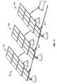
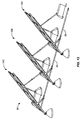
- Fig. 10 shows a row 90 of solar collector assemblies 10A, 10B, 10C shown in a morning, generally east-facing orientation while Figs. 11 and 12 illustrate row 90 in noon time and evening, generally west-facing orientations.
- Tilt assembly 50 includes driver 52 and drive rod 56 as is shown in Fig. 1 .
- tilt assembly 50 includes drive element couplers 92 coupling the outer ends 60 of drive elements 54 of assemblies 10A, 10B and of assemblies 10B, 10C.
- Fig. 13 is an enlarged view of a portion of assembly 10B of Fig. 12 illustrating the pivotal connections between drive element couplers 92 and outer end 60 of drive element 54.
- Drive element couplers 92 are similar to drive rod 56 having one clevis-type end 94 and a plain, cylindrical end 96 sized to fit within the clevis type end 94. Cylindrical end 96 has a number of holes 98 to permit the effective length of couplers 92 to be changed. Other techniques for changing the length of couplers 92 may also be used.
- the use of the pivotal connections at outer ends 60 of drive elements 54 makes the alignment of assemblies 10 in a row 90 of assemblies much less critical. This helps to permit rows 90 of assemblies 10 to be used on uneven, undulating or other support surfaces 14 that are not flat without the need for extensive, and expensive, site preparation.
- FIG. 18 A further example of a row 90 of solar collector assemblies 10 is illustrated in Fig. 18 .
- Some of the differences between the example of Fig. 18 and that shown in Figs. 1 and 11 include the use of a different arrangement for solar collector modules 22 and the use of a tilt assembly 402 midway along the row 90 instead of a tilt assembly 50 at the end of the row as shown in Fig. 1 .
- the construction of, and advantages accruing through the use of, tilt assembly 402 has been discussed above with reference to Figs. 19 , 20 and 21 .
- all solar collector assemblies 10 in Fig. 18 can be considered to be two rows of solar collector assemblies positioned along generally the same East-West path or line. Although three solar collector assemblies are shown one each side of tilt assembly 402 in row 90, in practice many more solar collector assemblies will typically constitute a single row 90.
- Another difference between row 90 of Fig. 18 and row 90 of Fig. 11 is the use of north bases 66 between adjacent solar collector assemblies 10 but the use of smaller north bases 66A, similar to south bases 28, at the ends of the rows and located in the gap 404 between assemblies 10 on either side of driver 400. It has been found that it is typically not necessary to use the larger north bases 66 when only a single support strut 70 is connected to the north base.
- Figs. 14-17 illustrate another example which uses a combiner box assembly 280 along each row of solar collector assemblies 10. Wires from each solar collector assembly 10 pass along drive element 54 and along drive element couplers 92 until reaching combiner box assembly 280. The wires, not shown in Figs. 14-17 , pass through an opening, not shown, in drive element coupler 92, into the open end 282 of a flexible hose 284, through flexible hose 284 and into combiner box 286. The proper movement of hose 284 is aided by the use of tray 287 which helps keep hose 284 from tangling, binding or reducing the minimum wire bend radius as drive element coupler 92 moves during the day. As shown in Fig. 17 , the angular orientation of hose 284 is such as to generally lie in a plane parallel to drive element 54.
- the determination of the weight for south bases 28 and north bases 66 can be made to be site-specific based upon the size and configuration of assemblies 12 or can be made based upon typical configurations for assemblies 12 and expected wind loads.
- the weight determination can be made by the final user or installer or by the manufacture of assemblies 12.
- One typical way for determining the weight of south and north bases 28, 66 is to provide the user or installer guidelines so that for a particular range of surface areas for assembly 12 oriented over a particular range of tilt angles, recommended weights for south and north bases 28, 66 can be provided for different ranges of expected wind speeds.
- the manufacturer can provide the user or installer with recommended weights for south and north bases 28, 66 based upon information for the particular installation.
- torque member 24 may have a variety of cross-sectional shapes including round and square, may have a partially or fully solid interior, may be made of one or more materials, and may have its various structural features vary along its length.
- Torque member 24 and rails 26, which act as a support or frame for solar collector modules 22, could be replaced by other solar collector support structure, such as a rigid rectangular platform. Therefore, tilt assembly 50 could be secured to structure other than torque member 24.
- the solar collector support structure could be mounted so to tilt not about a fixed tilt axis 42 but, for example, about a range of instantaneous tilt axes.
Claims (7)
- Kippanordnung für die Verwendung mit einer Sonnenkollektoranordnung (10) des Typs, der einen Rahmen (20) zum Halten eines Sonnenkollektors umfasst, für eine Bewegung um eine Kippachse (42) durch das Schwenken eines Antriebselements (54) zwischen ersten und zweiten Ausrichtungen, wobei die Kippanordnung umfasst:einen Antriebselement-Koppler (92), der mit dem Antriebselement (54) an einer Position entlang des Antriebselements (54), die durch eine erste Distanz von der Kippachse (42) beabstandet ist, verbunden ist, undeine Antriebseinrichtung (400), die umfasst:einen Antriebsrahmen (406),einen Antriebsarm (422), der an dem Antriebsrahmen (406) für eine Schwenkbewegung um eine Antriebsarmachse (420) montiert ist,wobei der Antriebsarm (422) zwischen dritten und vierten Ausrichtungen geschwenkt werden kann, wobei der Antriebsarm (422) einen inneren Teil, der sich von dem Antriebsrahmen (406) erstreckt, und einen äußeren Teil, der antreibend mit dem Antriebselement-Koppler (92) an einer Antriebsposition (424) entlang des Antriebsarms (422) verbunden ist, umfasst, wobei die Antriebsposition (424) von der Antriebsarmachse (420) durch eine zweite Distanz (426) beabstandet ist, undeinen Antriebsarm-Antriebsteil (428), der mit dem Antriebsarm (422) für eine Bewegung des Antriebsarms (422) zwischen den dritten und vierten Ausrichtungen gekoppelt ist,dadurch gekennzeichnet, dass der Antriebsrahmen (406) derart aufgebaut ist, dass der Antriebselement-Koppler (92) unter einem Teil des Antriebsrahmens (406) hindurchgeht, wenn der Antriebsarm (422) zwischen den dritten und vierten Ausrichtungen schwenkt.
- Anordnung nach Anspruch 1, wobei:die Antriebseinrichtung (400) weiterhin einen Antriebsarm-Halter (416) umfasst, der schwenkbar an dem Antriebsrahmen (406) für eine Schwenkbewegung um die Antriebsarmachse (420) montiert ist, wobei der Antriebsarm (422) an dem Antriebsarm-Halter (416) montiert ist, undder Antriebsarm-Antriebsteil (428) durch den Antriebsrahmen (406) gehalten wird.
- Anordnung nach Anspruch 1, wobei die ersten und zweiten Distanzen im Wesentlichen gleich sind.
- Anordnung nach Anspruch 1 oder 3, wobei die Antriebsarmachse (420) derart ausgerichtet werden kann, dass sie im Wesentlichen parallel zu der Kippachse (42) ist.
- Anordnung nach Anspruch 4, die weiterhin eine zweite Linie umfasst, die durch die zweite Distanz definiert wird, wobei die zweite Linie derart ausgerichtet werden kann, dass sie im Wesentlichen parallel zu einer durch die erste Distanz definierten ersten Linie ist, sodass die Bewegung des Antriebsarms (422) die Bewegung des Antriebselements (54) nachahmt.
- Anordnung nach Anspruch 4, wobei die Antriebseinrichtung (400) derart konfiguriert ist, dass eine Bewegung des Antriebsarms (422) zwischen den dritten und vierten Ausrichtungen im Wesentlichen eine Bewegung des Antriebselements (54) zwischen den ersten und zweiten Ausrichtungen nachahmt.
- Anordnung nach Anspruch 1 oder 6, die erste und zweite Antriebselement-Koppler umfasst, die sich in im Wesentlichen gegenüberliegenden Richtungen von dem äußeren Teil des Antriebsarms (422) erstrecken, sodass die Anordnung zwischen benachbarten Sonnenkollektoranordnungen in einer Reihe von Sonnenkollektoranordnungen verwendet werden kann.
Applications Claiming Priority (3)
| Application Number | Priority Date | Filing Date | Title |
|---|---|---|---|
| US89677507P | 2007-03-23 | 2007-03-23 | |
| US99159707P | 2007-11-30 | 2007-11-30 | |
| PCT/US2008/051800 WO2008118520A1 (en) | 2007-03-23 | 2008-01-23 | Tilt assembly for tracking solar collector assembly |
Publications (3)
| Publication Number | Publication Date |
|---|---|
| EP2140212A1 EP2140212A1 (de) | 2010-01-06 |
| EP2140212A4 EP2140212A4 (de) | 2013-07-24 |
| EP2140212B1 true EP2140212B1 (de) | 2016-03-23 |
Family
ID=39773478
Family Applications (3)
| Application Number | Title | Priority Date | Filing Date |
|---|---|---|---|
| EP08728118A Withdrawn EP2140211A1 (de) | 2007-03-23 | 2008-01-23 | Nachlauf-solarkollektorbaugruppe |
| EP08728137.4A Not-in-force EP2140212B1 (de) | 2007-03-23 | 2008-01-23 | Kippanordnung für nachlauf-sonnenkollektoranordnung |
| EP08713938.2A Not-in-force EP2130231B1 (de) | 2007-03-23 | 2008-01-23 | Solarkollektorbaugruppe und verfahren zur montage einer solarkollektor-anlage |
Family Applications Before (1)
| Application Number | Title | Priority Date | Filing Date |
|---|---|---|---|
| EP08728118A Withdrawn EP2140211A1 (de) | 2007-03-23 | 2008-01-23 | Nachlauf-solarkollektorbaugruppe |
Family Applications After (1)
| Application Number | Title | Priority Date | Filing Date |
|---|---|---|---|
| EP08713938.2A Not-in-force EP2130231B1 (de) | 2007-03-23 | 2008-01-23 | Solarkollektorbaugruppe und verfahren zur montage einer solarkollektor-anlage |
Country Status (9)
| Country | Link |
|---|---|
| US (3) | US8101849B2 (de) |
| EP (3) | EP2140211A1 (de) |
| JP (3) | JP5404431B2 (de) |
| KR (3) | KR20100015818A (de) |
| CN (2) | CN102176473B (de) |
| AU (2) | AU2008231261B2 (de) |
| CA (2) | CA2678786A1 (de) |
| IL (2) | IL200583A0 (de) |
| WO (3) | WO2008118518A1 (de) |
Families Citing this family (158)
| Publication number | Priority date | Publication date | Assignee | Title |
|---|---|---|---|---|
| US20070204860A1 (en) * | 2006-03-06 | 2007-09-06 | Rose Andrew F | Device for supporting, aligning, and cooling a solar panel |
| US8776781B2 (en) * | 2007-07-31 | 2014-07-15 | Sunpower Corporation | Variable tilt tracker for photovoltaic arrays |
| US8748733B2 (en) * | 2008-03-27 | 2014-06-10 | Panelclaw, Inc. | Solar module integration system |
| US8832938B2 (en) * | 2008-03-27 | 2014-09-16 | Panelclaw, Inc. | Ground mounted solar module integration system |
| CN102245979A (zh) * | 2008-10-11 | 2011-11-16 | 美国太阳能股份有限公司 | 高效安装的太阳能面板系统 |
| US8188414B2 (en) | 2008-12-23 | 2012-05-29 | Opel, Inc. | Grid support system for a tracker-mounted solar panel array for rooftop applications |
| ES2345084B1 (es) * | 2008-12-24 | 2011-07-22 | Global Solar Fund Partners Sarl | Dispositivo de seguimiento solar para paneles. |
| EP2394108A2 (de) * | 2009-01-26 | 2011-12-14 | Single Source Roofing Corporation | Mobile photovoltaik-panel-struktur und baugruppe |
| US7958886B2 (en) * | 2009-02-02 | 2011-06-14 | Sunpower Corporation | Torque arm assembly and method |
| US8500060B2 (en) * | 2009-02-10 | 2013-08-06 | The Boeing Company | Aircraft with a pressurized vessel |
| US8056865B2 (en) | 2009-03-05 | 2011-11-15 | The Boeing Company | Mechanism for changing the shape of a control surface |
| US8245459B2 (en) * | 2009-03-11 | 2012-08-21 | First Solar, Inc | Rooftop photovoltaic module mounting system |
| US8316590B2 (en) | 2009-03-20 | 2012-11-27 | Northern States Metals Company | Support system for solar panels |
| US8256169B2 (en) | 2009-03-20 | 2012-09-04 | Northern States Metals Company | Support system for solar panels |
| WO2010118236A1 (en) * | 2009-04-08 | 2010-10-14 | Ap Alternatives, Llc | Solar panel supports and method |
| EP2244031A3 (de) * | 2009-04-24 | 2012-09-19 | ZYRUS Beteiligungsgesellschaft mbH & Co. Patente I KG | Solarkollektor, Verbundscheibe und Absorber sowie Verwendung eines derartigen Absorbers |
| KR101040754B1 (ko) * | 2009-05-07 | 2011-06-14 | 오쏠라 유한회사 | 태양광 트래킹 장치용 합성수지재 베어링 |
| WO2010129087A2 (en) * | 2009-05-08 | 2010-11-11 | Sunpower Corporation | Photovoltaic solar collection and tracking system |
| DE102009020446A1 (de) * | 2009-05-08 | 2010-11-11 | A+F Gmbh | Photovoltaikanlage und Verfahren zum Betrieb einer Photovoltaikanlage |
| ES2384844B1 (es) * | 2009-05-26 | 2013-07-04 | Young & Franklin, Inc | Sistema de accionamiento basado en actuador para colector solar. |
| US8291653B2 (en) * | 2009-06-19 | 2012-10-23 | Unirac, Inc. | Modular structural framing system |
| US8640423B2 (en) * | 2009-09-04 | 2014-02-04 | The University Of Houston System | Apparatus and method for mounting a renewable energy panel on a roof |
| US20100139741A1 (en) * | 2009-10-12 | 2010-06-10 | Wares Brian S | Frame-Integrated Pivot Bearing For Solar Collector Assembly |
| ES2375042B2 (es) * | 2009-10-27 | 2012-09-07 | Hierros Y Aplanaciones S.A. (Hiasa) | Seguidor solar fotovoltaico. |
| US20120222372A1 (en) * | 2009-11-18 | 2012-09-06 | Hilber Franz | Adjusting device of a stationary photovoltaic system |
| US9347692B2 (en) * | 2009-11-24 | 2016-05-24 | Guy A. Pizzarello | Low profile solar tracking systems and methods |
| US20110137466A1 (en) * | 2009-12-08 | 2011-06-09 | Miller Daniel H | Method, system, and controller for controlling heliostat mirrors |
| US9929296B1 (en) | 2009-12-22 | 2018-03-27 | Sunpower Corporation | Edge reflector or refractor for bifacial solar module |
| WO2011080335A2 (en) * | 2009-12-31 | 2011-07-07 | Saint-Gobain Performance Plastics Pampus Gmbh | Renewable energy source including an energy conversion structure and a bearing component |
| US8455806B2 (en) | 2010-01-18 | 2013-06-04 | Sunpower Corporation | Photovoltaic assembly for use in diffuse weather conditions and related methods |
| US9321583B2 (en) | 2010-05-24 | 2016-04-26 | Opterra Energy Services, Inc. | Pallet assembly for transport of solar module array pre-assembly |
| US8584338B2 (en) | 2010-05-24 | 2013-11-19 | Chevron U.S.A. Inc. | Solar module array pre-assembly method |
| CN101893896B (zh) * | 2010-06-18 | 2012-05-30 | 苏州正信电子科技有限公司 | 一种太阳能板的定时追日装置 |
| CN201724457U (zh) * | 2010-06-24 | 2011-01-26 | 威升开发股份有限公司 | 太阳能追日面板的单轴传动装置 |
| CA2712036A1 (en) * | 2010-07-05 | 2012-01-05 | George G. Lessard | Low profile roof mountable multi axis solar tracker |
| US20110138599A1 (en) * | 2010-07-29 | 2011-06-16 | John Bellacicco | Mounting system supporting slidable installation of a plurality of solar panels as a unit |
| WO2012018360A1 (en) * | 2010-08-06 | 2012-02-09 | First Solar, Inc. | Folding mount for photovoltaic modules |
| AT510324B1 (de) * | 2010-08-23 | 2012-08-15 | Hartmut Dipl Ing Schneider | Spiegelmodul |
| KR101022987B1 (ko) * | 2010-09-17 | 2011-03-22 | (주) 파루 | 태양 추적 센서를 이용한 단축 대형 구동 장치 |
| US8684190B2 (en) * | 2010-11-19 | 2014-04-01 | Warren Abar | Multi-position solar panel rack |
| US9127724B2 (en) | 2010-12-10 | 2015-09-08 | Means Industries, Inc. | Electromechanical apparatus for use with a coupling assembly and controllable coupling assembly including such apparatus |
| US9541141B2 (en) | 2010-12-10 | 2017-01-10 | Means Industries, Inc. | Electronic vehicular transmission, controllable coupling assembly and coupling member for use in the assembly |
| US9186977B2 (en) | 2011-08-26 | 2015-11-17 | Means Industries, Inc. | Drive system including a transmission for a hybrid electric vehicle |
| US9255614B2 (en) | 2010-12-10 | 2016-02-09 | Means Industries, Inc. | Electronic vehicular transmission and coupling and control assembly for use therein |
| US8813929B2 (en) | 2010-12-10 | 2014-08-26 | Means Industries, Inc. | Controllable coupling assembly |
| US10677296B2 (en) | 2010-12-10 | 2020-06-09 | Means Industries, Inc. | Electronic, high-efficiency vehicular transmission, overrunning, non-friction coupling and control assembly and switchable linear actuator device for use therein |
| US8888637B2 (en) | 2010-12-10 | 2014-11-18 | Means Industries, Inc. | Vehicle drive system including a transmission |
| US9377061B2 (en) | 2010-12-10 | 2016-06-28 | Means Industries, Inc. | Electromagnetic system for controlling the operating mode of an overrunning coupling assembly and overrunning coupling and control assembly including the system |
| US9874252B2 (en) | 2010-12-10 | 2018-01-23 | Means Industries, Inc. | Electronic, high-efficiency vehicular transmission, overrunning, non-friction coupling and control assembly and switchable linear actuator device for use therein |
| US9638266B2 (en) | 2010-12-10 | 2017-05-02 | Means Industries, Inc. | Electronic vehicular transmission including a sensor and coupling and control assembly for use therein |
| US9435387B2 (en) | 2010-12-10 | 2016-09-06 | Means Industries, Inc. | Device and apparatus for controlling the operating mode of a coupling assembly, coupling and control assembly and electric motor disconnect and pass through assemblies |
| US8646587B2 (en) | 2010-12-10 | 2014-02-11 | Means Industries, Inc. | Strut for a controllable one-way clutch |
| US9234552B2 (en) | 2010-12-10 | 2016-01-12 | Means Industries, Inc. | Magnetic system for controlling the operating mode of an overrunning coupling assembly and overrunning coupling and magnetic control assembly having same |
| EP2649339A4 (de) | 2010-12-10 | 2018-03-14 | Means Industries, Inc. | Elektromechanisch betätigbare kupplung und steuereinheit dafür |
| ES2401184B1 (es) * | 2011-01-04 | 2014-02-28 | Ingenieria Ambiental Helios S.L. | Sistema de captacion de energia solar |
| US9482449B2 (en) | 2011-01-14 | 2016-11-01 | Sunpower Corporation | Support for solar energy collectors |
| TWM413839U (en) * | 2011-01-14 | 2011-10-11 | Moteck Electric Corp | Sun-tracking device for solar panel |
| US8407950B2 (en) | 2011-01-21 | 2013-04-02 | First Solar, Inc. | Photovoltaic module support system |
| US8650811B2 (en) * | 2011-02-04 | 2014-02-18 | The Boeing Company | Solar collector frame |
| US8839573B2 (en) | 2011-02-11 | 2014-09-23 | Northern States Metals Company | Spring clip |
| TR201101718A2 (tr) * | 2011-02-22 | 2012-09-21 | Hse H�T�T Solar Enerj� Anon�M ��Rket� | Güneş oluğu sistemlerindeki termal alıcılar için destek mekanizması. |
| US8572909B2 (en) * | 2011-03-24 | 2013-11-05 | Solar Mounting Solutions, LLC | Flat roof solar racking system |
| US9117951B2 (en) * | 2011-03-30 | 2015-08-25 | Enersolar Co., Ltd. | Solar cell module support structure |
| AU2012283945B2 (en) * | 2011-07-19 | 2017-09-28 | Brittmore Group LLC | Installation system for photovoltaic modules |
| EP3009766B1 (de) | 2011-08-12 | 2017-10-04 | First Solar, Inc | Sonnenverfolgungssystem |
| US9207000B2 (en) * | 2011-08-22 | 2015-12-08 | Darin Kruse | Solar apparatus support structures and systems |
| US8920077B2 (en) | 2011-08-22 | 2014-12-30 | Darin Kruse | Post tensioned foundations, apparatus and associated methods |
| DE202011106790U1 (de) * | 2011-10-17 | 2011-11-18 | A+F Gmbh | Sonnenkollektorgestell |
| ES2408505B1 (es) * | 2011-11-03 | 2014-03-17 | Mecanizados Solares, S.L. | Seguidor solar de eje polar. |
| KR101248597B1 (ko) * | 2011-11-07 | 2013-03-28 | 한국전력기술 주식회사 | 태양광발전모듈의 적층시스템 |
| WO2013085776A2 (en) * | 2011-12-08 | 2013-06-13 | Sunedison, Llc | Adjustable tilt angle device for photovoltaic arrays |
| US9035168B2 (en) | 2011-12-21 | 2015-05-19 | Sunpower Corporation | Support for solar energy collectors |
| JP5936864B2 (ja) * | 2012-01-18 | 2016-06-22 | Sus株式会社 | 太陽光発電装置 |
| US10965241B2 (en) * | 2012-02-05 | 2021-03-30 | Tien Solar LLC | Solar plant support structure |
| WO2013119218A1 (en) * | 2012-02-08 | 2013-08-15 | Preformed Line Products | Solar panel clamp |
| CN102738272B (zh) * | 2012-04-25 | 2016-08-03 | 杭州帷盛科技有限公司 | 一种太阳能光伏系统及其安装方法 |
| US20130333689A1 (en) * | 2012-06-19 | 2013-12-19 | Bruce Sho Umemoto | Dual axis synchronized tracking system |
| US20130334393A1 (en) * | 2012-06-19 | 2013-12-19 | Bruce Sho Umemoto | Dual axis solar array tracker |
| US10720541B2 (en) | 2012-06-26 | 2020-07-21 | Lockheed Martin Corporation | Foldable solar tracking system, assembly and method for assembly, shipping and installation of the same |
| CA2889317A1 (en) * | 2012-07-23 | 2014-01-30 | Magna International Inc. | Single axis solar tracker |
| CN102790105B (zh) * | 2012-08-13 | 2014-08-06 | 友达光电股份有限公司 | 太阳能模块 |
| US9093582B2 (en) | 2012-09-19 | 2015-07-28 | Opterra Energy Services, Inc. | Solar canopy assembly |
| US9093583B2 (en) | 2012-09-19 | 2015-07-28 | Opterra Energy Services, Inc. | Folding solar canopy assembly |
| US20140077055A1 (en) | 2012-09-19 | 2014-03-20 | Chevron U.S.A Inc.. | Bracing assembly |
| US9496822B2 (en) | 2012-09-24 | 2016-11-15 | Lockheed Martin Corporation | Hurricane proof solar tracker |
| US9395104B2 (en) * | 2012-09-28 | 2016-07-19 | Sunpower Corporation | Integrated torque coupling and mount |
| WO2017019719A2 (en) * | 2015-07-27 | 2017-02-02 | Smash Solar, Inc. | Sensing, interlocking solar panel system and installation method |
| US9142700B2 (en) | 2012-10-16 | 2015-09-22 | Ironridge, Inc. | Assembly for supporting and grounding solar panels |
| US9466749B1 (en) | 2012-12-10 | 2016-10-11 | Nextracker Inc. | Balanced solar tracker clamp |
| US10008975B2 (en) | 2012-12-10 | 2018-06-26 | Nextracker Inc. | Clamp assembly for solar tracker |
| JP2016504901A (ja) | 2012-12-10 | 2016-02-12 | ネクストラッカー インコーポレイテッドNEXTracker Inc. | 水平バランス太陽光追尾装置 |
| US9766319B2 (en) | 2012-12-10 | 2017-09-19 | Nextracker Inc. | Off-set drive assembly for solar tracker |
| US9568900B2 (en) | 2012-12-11 | 2017-02-14 | Opterra Energy Services, Inc. | Systems and methods for regulating an alternative energy source that is decoupled from a power grid |
| US9347691B2 (en) | 2013-02-26 | 2016-05-24 | Solarcity Corporation | Torque Tube Mounted Photovoltaic Apparatus, System, and Method |
| US9279457B2 (en) | 2013-03-15 | 2016-03-08 | Sunpower Corporation | Nested torque tubes for photovoltaic tracking systems |
| US10254011B2 (en) * | 2013-04-02 | 2019-04-09 | Energy Related Devices, Inc. | Photovoltaic module mounting to rubber tires |
| US9303663B2 (en) | 2013-04-11 | 2016-04-05 | Northern States Metals Company | Locking rail alignment system |
| CN103258885B (zh) | 2013-06-05 | 2015-12-23 | 友达光电股份有限公司 | 用以支撑太阳能模块的支架 |
| USD747262S1 (en) | 2013-06-28 | 2016-01-12 | Dow Global Technologies Llc | Photovoltaic back panel |
| USD733645S1 (en) | 2013-06-28 | 2015-07-07 | Dow Global Technologies Llc | Corner connector for a photovoltaic module frame |
| US9080792B2 (en) | 2013-07-31 | 2015-07-14 | Ironridge, Inc. | Method and apparatus for mounting solar panels |
| US9371868B2 (en) | 2013-08-27 | 2016-06-21 | Means Industries, Inc. | Coupling member subassembly for use in controllable coupling assembly and electromechanical apparatus having a pair of simultaneously actuated elements for use in the subassembly |
| US10533618B2 (en) | 2013-09-26 | 2020-01-14 | Means Industries, Inc. | Overrunning, non-friction coupling and control assembly, engageable coupling assembly and locking member for use in the assemblies |
| US10250183B2 (en) * | 2013-10-25 | 2019-04-02 | Joseph O. Edmunds | Modular solar power generator |
| JP6260269B2 (ja) * | 2013-12-27 | 2018-01-17 | ダイキン工業株式会社 | 太陽光発電システムの設置方法及び太陽光発電システム |
| US9482294B2 (en) | 2014-02-19 | 2016-11-01 | Means Industries, Inc. | Coupling and control assembly including a sensor |
| US9562574B2 (en) | 2014-02-19 | 2017-02-07 | Means Industries, Inc. | Controllable coupling assembly and coupling member for use in the assembly |
| WO2015166855A1 (ja) * | 2014-04-28 | 2015-11-05 | クリーンエナジーファクトリー株式会社 | 太陽光発電プラント施工法 |
| USD747111S1 (en) * | 2014-06-18 | 2016-01-12 | Daniel Raul Simoes | Picture mount |
| ES2557501B1 (es) * | 2014-07-25 | 2016-11-02 | Solatom Csp, S.L. | Sistema solar fresnel lineal transportable en un contenedor de mercancías |
| US10619681B2 (en) | 2014-09-16 | 2020-04-14 | Means Industries, Inc. | Overrunning, non-friction coupling and control assemblies and switchable linear actuator device and reciprocating electromechanical apparatus for use therein |
| US20160195303A1 (en) * | 2015-01-05 | 2016-07-07 | Sunpower Corporation | Solar tracker drive mount |
| US9482297B2 (en) | 2015-04-01 | 2016-11-01 | Means Industries, Inc. | Controllable coupling assembly having forward and reverse backlash |
| JP6231515B2 (ja) * | 2015-04-22 | 2017-11-15 | クリーンエナジーファクトリー株式会社 | 太陽光発電プラント施工法 |
| US10938218B2 (en) | 2015-12-28 | 2021-03-02 | Sunpower Corporation | Solar tracker system |
| US9923513B2 (en) * | 2016-05-13 | 2018-03-20 | Boson Robotics Ltd. | Cleaning mechanism having water spray function and photovoltaic panel cleaning equipment having same |
| US10236690B2 (en) * | 2016-06-30 | 2019-03-19 | Sunpower Corporation | Backfeed power supply for solar power system |
| USD822890S1 (en) | 2016-09-07 | 2018-07-10 | Felxtronics Ap, Llc | Lighting apparatus |
| WO2018045423A1 (en) * | 2016-09-07 | 2018-03-15 | C I Corporation Pty Ltd | A dual axis solar tracker assembly |
| CN106452322B (zh) * | 2016-11-04 | 2018-10-02 | 浙江电腾云光伏科技有限公司 | 一种太阳能光伏板的调节支架 |
| CN108233851A (zh) * | 2016-12-12 | 2018-06-29 | 浙江海洋大学 | 一种太阳能智能电量控制系统 |
| CN107340785B (zh) * | 2016-12-15 | 2021-05-18 | 江苏林洋新能源科技有限公司 | 一种基于智能化控制的双面光伏电池组件跟踪方法及控制器 |
| US20180175782A1 (en) * | 2016-12-20 | 2018-06-21 | Sane Innovations, LLC. | Support Structure for Maximizing Solar-Panel Efficiency and Facilitating Solar-Panel Installation |
| WO2018115942A1 (en) * | 2016-12-22 | 2018-06-28 | Woosnam Calvin Henry | Universal mount tripod solar tracker system |
| PT3364123T (pt) | 2017-02-17 | 2020-01-15 | Nexans Solar Tech | Rastreador solar com acoplamento cinemático |
| CN106988457A (zh) * | 2017-03-29 | 2017-07-28 | 武汉理工大学 | 一种光热互补发电的智能玻璃幕墙及工作方法 |
| CN106972821B (zh) * | 2017-04-28 | 2023-07-04 | 湖南合汇光伏科技有限公司 | 一种可旋转双倾角的光伏组件安装塔架 |
| US10775030B2 (en) | 2017-05-05 | 2020-09-15 | Flex Ltd. | Light fixture device including rotatable light modules |
| USD846793S1 (en) | 2017-08-09 | 2019-04-23 | Flex Ltd. | Lighting module locking mechanism |
| USD833061S1 (en) | 2017-08-09 | 2018-11-06 | Flex Ltd. | Lighting module locking endcap |
| USD877964S1 (en) | 2017-08-09 | 2020-03-10 | Flex Ltd. | Lighting module |
| USD832494S1 (en) | 2017-08-09 | 2018-10-30 | Flex Ltd. | Lighting module heatsink |
| USD872319S1 (en) | 2017-08-09 | 2020-01-07 | Flex Ltd. | Lighting module LED light board |
| USD862777S1 (en) | 2017-08-09 | 2019-10-08 | Flex Ltd. | Lighting module wide distribution lens |
| USD832495S1 (en) | 2017-08-18 | 2018-10-30 | Flex Ltd. | Lighting module locking mechanism |
| USD862778S1 (en) | 2017-08-22 | 2019-10-08 | Flex Ltd | Lighting module lens |
| USD888323S1 (en) | 2017-09-07 | 2020-06-23 | Flex Ltd | Lighting module wire guard |
| WO2019113137A2 (en) | 2017-12-04 | 2019-06-13 | Gordon John Taylor Ii | Data retrieval and transmitting marine exploration vessel systems |
| FR3074985B1 (fr) * | 2017-12-07 | 2020-05-08 | Electricite De France | Module photovoltaique flottant |
| TWI645145B (zh) * | 2018-02-14 | 2018-12-21 | 吳建興 | 追日系統與追日方法 |
| US11283395B2 (en) | 2018-03-23 | 2022-03-22 | Nextracker Inc. | Multiple actuator system for solar tracker |
| US11165384B1 (en) | 2018-05-18 | 2021-11-02 | Joseph McCABE | Method for hanging PV modules |
| US11387771B2 (en) | 2018-06-07 | 2022-07-12 | Nextracker Llc | Helical actuator system for solar tracker |
| WO2020006575A1 (en) | 2018-06-29 | 2020-01-02 | Nextracker Inc. | Solar module tracker system optimized for bifacial solar modules |
| US11121671B2 (en) * | 2018-09-05 | 2021-09-14 | Ojjo, Inc. | A-frame foundation system for single-axis trackers with weak axis support |
| US10615739B2 (en) * | 2018-09-05 | 2020-04-07 | Ojjo, Inc. | Optimized truss foundations, adapters for optimized truss foundations, and related systems and methods |
| CN113906669B (zh) * | 2019-03-21 | 2024-02-02 | Ojjo股份有限公司 | 用于单轴跟踪器的力矩优化桁架基础 |
| US11050383B2 (en) | 2019-05-21 | 2021-06-29 | Nextracker Inc | Radial cam helix with 0 degree stow for solar tracker |
| USD905626S1 (en) | 2019-07-25 | 2020-12-22 | Nextracker Inc. | Panel rail saddle for solar module |
| US11466900B2 (en) | 2019-09-20 | 2022-10-11 | King Fahd University Of Petroleum And Minerals | Dual-axis hydraulic system for solar tracking |
| EP4197099A1 (de) * | 2020-08-17 | 2023-06-21 | Nextracker LLC | Mehrwandige verbindung über pfeiler |
| IT202100009347A1 (it) * | 2021-04-14 | 2022-10-14 | Johann Czaloun | Un impianto fotovoltaico con una struttura orientabile |
| WO2022241548A1 (en) * | 2021-05-17 | 2022-11-24 | Stella Power Inc. | Solar panel ground anchoring system |
| JP6966137B1 (ja) * | 2021-06-03 | 2021-11-10 | 晟平 李 | ソーラーパネル用架台 |
| US11728760B2 (en) * | 2021-06-16 | 2023-08-15 | Tectonicus Constructs, Llc | Pivotable support structure for cross canal solar array |
| WO2023059835A1 (en) * | 2021-10-06 | 2023-04-13 | Boguess Brian C | Transportable and multi configurable, modular power platforms |
| CN114524056B (zh) * | 2022-02-16 | 2023-04-25 | 广西柳工机械股份有限公司 | 一种自动安装设备 |
| WO2023240029A2 (en) * | 2022-06-07 | 2023-12-14 | Mark Holtzapple | Systems and methods for providing a solar structure |
Family Cites Families (61)
| Publication number | Priority date | Publication date | Assignee | Title |
|---|---|---|---|---|
| US3716234A (en) * | 1970-10-29 | 1973-02-13 | J Lancellotti | Basketball equipment support with carrying case |
| US4187123A (en) | 1975-10-21 | 1980-02-05 | Diggs Richard E | Directionally controlled array of solar power units |
| US4000734A (en) | 1975-11-06 | 1977-01-04 | Matlock William C | Solar energy converter |
| US4103672A (en) * | 1976-05-21 | 1978-08-01 | Meyer Warren A | Solar collector |
| US4173213A (en) * | 1976-09-15 | 1979-11-06 | Kelly Donald A | Solar power system, with high concentration, linear reflective solar panels |
| US4108154A (en) * | 1976-11-22 | 1978-08-22 | Homer Van Dyke | Solar energy collection system |
| GB1600705A (en) * | 1977-05-19 | 1981-10-21 | Guernsey Gas Light | Solar tracking device |
| DE2758067A1 (de) * | 1977-12-24 | 1979-07-05 | Bbc Brown Boveri & Cie | Solarkollektoranlage |
| US4184482A (en) * | 1978-09-29 | 1980-01-22 | Cohen Elie | Solar energy collecting system |
| FR2461331A1 (fr) * | 1979-07-10 | 1981-01-30 | Soterem Sa | Support orienteur 1 axe |
| US4345582A (en) * | 1979-11-19 | 1982-08-24 | Aharon Naaman B | System for the utilization of solar energy |
| US4404465A (en) | 1980-01-21 | 1983-09-13 | Rca Corporation | Array positioning system |
| US4365617A (en) | 1980-10-02 | 1982-12-28 | Eckhard Bugash | Solar energy heating system |
| US4316448A (en) * | 1980-10-06 | 1982-02-23 | Pennwalt Corporation | Solar energy concentrator system |
| US4429178A (en) | 1981-07-13 | 1984-01-31 | Acurex Solar Corporation | Solar tracking apparatus utilizing photovoltaic flat panels and method |
| DE3371689D1 (en) * | 1983-01-14 | 1987-06-25 | Seifert Dieter | Tracking device |
| JPS606912A (ja) * | 1983-06-24 | 1985-01-14 | Takashi Mori | 太陽光収集装置 |
| JPS60169173A (ja) | 1984-02-13 | 1985-09-02 | Agency Of Ind Science & Technol | 太陽光発電装置 |
| AU581977B2 (en) | 1985-04-09 | 1989-03-09 | Raymond Henry Dow | Solar array assembly |
| AP29A (en) | 1985-07-24 | 1988-12-26 | The State Of Western Australia C/O Western Australian Dept Of Agriculture | Solar tracking device. |
| US4832001A (en) | 1987-05-28 | 1989-05-23 | Zomeworks Corporation | Lightweight solar panel support |
| US4855167A (en) * | 1988-09-22 | 1989-08-08 | Biehl Harold A | Shaded outdoor parking area |
| JPH03145168A (ja) | 1989-10-31 | 1991-06-20 | Canon Inc | 太陽光発電装置の追尾架台 |
| US4995377A (en) * | 1990-06-29 | 1991-02-26 | Eiden Glenn E | Dual axis solar collector assembly |
| US5228924A (en) | 1991-11-04 | 1993-07-20 | Mobil Solar Energy Corporation | Photovoltaic panel support assembly |
| US5253637A (en) * | 1992-03-12 | 1993-10-19 | Maiden Miles M | Hyperfocal tracking solar thermal collector |
| US5319905A (en) * | 1992-09-28 | 1994-06-14 | Spar Aerospace Limited | Panel array deployment apparatus |
| JP3343744B2 (ja) * | 1993-05-20 | 2002-11-11 | 三菱電機照明株式会社 | 緩衝包装材組立体 |
| JP2605251B2 (ja) * | 1993-05-31 | 1997-04-30 | セイコープレシジョン株式会社 | 三脚の固定装置 |
| RU2145692C1 (ru) * | 1993-06-01 | 2000-02-20 | Александр Эдуардович Бергер | Механизм наведения на солнце |
| JPH0769344A (ja) * | 1993-08-31 | 1995-03-14 | Takashima Kk | 積重ね可能な折畳式コンテナー |
| JPH07263736A (ja) * | 1994-03-18 | 1995-10-13 | Sanyo Electric Co Ltd | 太陽電池架台 |
| JPH0878715A (ja) * | 1994-09-07 | 1996-03-22 | Showa Shell Sekiyu Kk | 太陽電池ユニット |
| US5685151A (en) | 1994-09-30 | 1997-11-11 | Ross; Randy | U.S. solar power supply |
| US5542409A (en) * | 1995-01-06 | 1996-08-06 | Sampayo; Eduardo A. | Solar concentrator system |
| JPH08260608A (ja) * | 1995-03-23 | 1996-10-08 | Misawa Homes Co Ltd | 屋根ユニット |
| JP3825843B2 (ja) * | 1996-09-12 | 2006-09-27 | キヤノン株式会社 | 太陽電池モジュール |
| EP0945343A1 (de) * | 1998-03-26 | 1999-09-29 | Fokker Space B.V. | System zur kinematischen Verbindung von benachbarten Paneelen in einer Paneelanordnung |
| US6058930A (en) | 1999-04-21 | 2000-05-09 | Shingleton; Jefferson | Solar collector and tracker arrangement |
| JP3577430B2 (ja) * | 1999-06-09 | 2004-10-13 | シャープ株式会社 | 太陽電池セルおよびその製造方法 |
| JP4313897B2 (ja) * | 1999-06-22 | 2009-08-12 | 三井造船株式会社 | 太陽電池モジュールの可動式架台 |
| ES2322224T3 (es) * | 1999-09-01 | 2009-06-18 | Kaneka Corporation | Modulo de celula solar de capa fina y su procedimiento de fabricacion. |
| KR200182863Y1 (ko) | 1999-12-27 | 2000-05-15 | 라제건 | 텐트폴의 연결구조 |
| WO2001055651A1 (en) | 2000-01-27 | 2001-08-02 | Haber Michael B | Solar panel tilt mechanism |
| JP2001332756A (ja) * | 2000-05-25 | 2001-11-30 | Canon Inc | 太陽電池モジュール及びその施工方法及び梱包方法 |
| JP2002026342A (ja) * | 2000-06-30 | 2002-01-25 | Canon Inc | 太陽電池モジュール及び太陽電池モジュールの梱包方法 |
| JP3958518B2 (ja) * | 2000-12-07 | 2007-08-15 | 積水樹脂株式会社 | 太陽光発電装置付き防雪柵 |
| US6971756B2 (en) * | 2000-12-18 | 2005-12-06 | Svv Technology Innovations, Inc. | Apparatus for collecting and converting radiant energy |
| US6563040B2 (en) * | 2001-10-11 | 2003-05-13 | Pinnacle West Capital Corporation | Structure for supporting a photovoltaic module in a solar energy collection system |
| JP3855160B2 (ja) * | 2002-03-25 | 2006-12-06 | 幹夫 木下 | 太陽放射集中装置 |
| WO2004063567A2 (en) * | 2002-09-13 | 2004-07-29 | Skybuilt Power, Llc | Mobile power system |
| US6760988B2 (en) * | 2002-11-25 | 2004-07-13 | William C. Bardeleben | Novelty device for mounting on a vehicle antenna |
| AU2004221388B2 (en) * | 2003-03-18 | 2007-02-01 | Sunpower Corporation, Systems | Tracking solar collector assembly |
| JP4737940B2 (ja) * | 2004-02-26 | 2011-08-03 | 京セラ株式会社 | 太陽電池素子の梱包方法 |
| US7905227B2 (en) * | 2004-03-30 | 2011-03-15 | Energy Innovations, Inc. | Self-ballasting solar collector |
| JP2005317588A (ja) * | 2004-04-27 | 2005-11-10 | Kyocera Corp | 太陽光発電装置 |
| DE102004023043B4 (de) * | 2004-05-06 | 2007-01-18 | Doko, Gilbert, Dr.-Ing. | Transportable Anlage zur Solarstromerzeugung |
| JP4663372B2 (ja) * | 2005-03-31 | 2011-04-06 | 三洋電機株式会社 | 太陽電池モジュール |
| CZ16891U1 (cs) * | 2006-08-16 | 2006-09-21 | Fvi S. R. O. | Soustava fotovoltaických clánku na panelech s polohováním |
| WO2008154945A1 (en) * | 2007-06-21 | 2008-12-24 | Conergy Ag | Modular pivotable solar collector arrangement |
| US8776781B2 (en) * | 2007-07-31 | 2014-07-15 | Sunpower Corporation | Variable tilt tracker for photovoltaic arrays |
-
2008
- 2008-01-23 KR KR1020097022134A patent/KR20100015818A/ko not_active Application Discontinuation
- 2008-01-23 CN CN2011100843009A patent/CN102176473B/zh not_active Expired - Fee Related
- 2008-01-23 JP JP2009554604A patent/JP5404431B2/ja not_active Expired - Fee Related
- 2008-01-23 AU AU2008231261A patent/AU2008231261B2/en not_active Ceased
- 2008-01-23 EP EP08728118A patent/EP2140211A1/de not_active Withdrawn
- 2008-01-23 EP EP08728137.4A patent/EP2140212B1/de not_active Not-in-force
- 2008-01-23 WO PCT/US2008/051767 patent/WO2008118518A1/en active Application Filing
- 2008-01-23 KR KR1020097022132A patent/KR20100015816A/ko not_active Application Discontinuation
- 2008-01-23 CN CN200880009482XA patent/CN101641798B/zh not_active Expired - Fee Related
- 2008-01-23 CA CA002678786A patent/CA2678786A1/en not_active Abandoned
- 2008-01-23 KR KR1020097022130A patent/KR20100015814A/ko not_active Application Discontinuation
- 2008-01-23 WO PCT/US2008/051779 patent/WO2008118519A1/en active Application Filing
- 2008-01-23 EP EP08713938.2A patent/EP2130231B1/de not_active Not-in-force
- 2008-01-23 CA CA002678790A patent/CA2678790A1/en not_active Abandoned
- 2008-01-23 JP JP2009554605A patent/JP5230025B2/ja not_active Expired - Fee Related
- 2008-01-23 AU AU2008231262A patent/AU2008231262B2/en not_active Ceased
- 2008-01-23 WO PCT/US2008/051800 patent/WO2008118520A1/en active Application Filing
- 2008-01-29 US US12/021,727 patent/US8101849B2/en active Active
- 2008-01-29 US US12/021,682 patent/US9243818B2/en active Active
-
2009
- 2009-08-25 IL IL200583A patent/IL200583A0/en unknown
- 2009-08-25 IL IL200584A patent/IL200584A0/en unknown
-
2012
- 2012-01-23 US US13/356,476 patent/US20120187058A1/en not_active Abandoned
-
2013
- 2013-09-04 JP JP2013183260A patent/JP5850344B2/ja not_active Expired - Fee Related
Also Published As
Similar Documents
| Publication | Publication Date | Title |
|---|---|---|
| EP2140212B1 (de) | Kippanordnung für nachlauf-sonnenkollektoranordnung | |
| EP1604407B1 (de) | Nachlauf-sonnenkollektorbaugruppe | |
| CA2678803C (en) | Tilt assembly for tracking solar collector assembly | |
| AU2011204772B2 (en) | Tilt assembly for tracking solar collector assembly | |
| AU2011211412B2 (en) | Stackable tracking solar collector assembly |
Legal Events
| Date | Code | Title | Description |
|---|---|---|---|
| PUAI | Public reference made under article 153(3) epc to a published international application that has entered the european phase |
Free format text: ORIGINAL CODE: 0009012 |
|
| 17P | Request for examination filed |
Effective date: 20091009 |
|
| AK | Designated contracting states |
Kind code of ref document: A1 Designated state(s): AT BE BG CH CY CZ DE DK EE ES FI FR GB GR HR HU IE IS IT LI LT LU LV MC MT NL NO PL PT RO SE SI SK TR |
|
| DAX | Request for extension of the european patent (deleted) | ||
| A4 | Supplementary search report drawn up and despatched |
Effective date: 20130621 |
|
| RIC1 | Information provided on ipc code assigned before grant |
Ipc: F24J 2/54 20060101ALI20130617BHEP Ipc: H01L 31/042 20060101ALI20130617BHEP Ipc: F24J 2/46 20060101AFI20130617BHEP |
|
| REG | Reference to a national code |
Ref country code: DE Ref legal event code: R079 Ref document number: 602008043040 Country of ref document: DE Free format text: PREVIOUS MAIN CLASS: F24J0002380000 Ipc: F24J0002460000 |
|
| GRAP | Despatch of communication of intention to grant a patent |
Free format text: ORIGINAL CODE: EPIDOSNIGR1 |
|
| RIC1 | Information provided on ipc code assigned before grant |
Ipc: H01L 31/042 20140101ALI20151006BHEP Ipc: F24J 2/54 20060101ALI20151006BHEP Ipc: F24J 2/46 20060101AFI20151006BHEP |
|
| INTG | Intention to grant announced |
Effective date: 20151027 |
|
| GRAS | Grant fee paid |
Free format text: ORIGINAL CODE: EPIDOSNIGR3 |
|
| GRAA | (expected) grant |
Free format text: ORIGINAL CODE: 0009210 |
|
| AK | Designated contracting states |
Kind code of ref document: B1 Designated state(s): AT BE BG CH CY CZ DE DK EE ES FI FR GB GR HR HU IE IS IT LI LT LU LV MC MT NL NO PL PT RO SE SI SK TR |
|
| REG | Reference to a national code |
Ref country code: GB Ref legal event code: FG4D |
|
| REG | Reference to a national code |
Ref country code: CH Ref legal event code: EP |
|
| REG | Reference to a national code |
Ref country code: AT Ref legal event code: REF Ref document number: 783557 Country of ref document: AT Kind code of ref document: T Effective date: 20160415 |
|
| REG | Reference to a national code |
Ref country code: IE Ref legal event code: FG4D |
|
| REG | Reference to a national code |
Ref country code: DE Ref legal event code: R096 Ref document number: 602008043040 Country of ref document: DE |
|
| REG | Reference to a national code |
Ref country code: LT Ref legal event code: MG4D |
|
| REG | Reference to a national code |
Ref country code: NL Ref legal event code: MP Effective date: 20160323 |
|
| PG25 | Lapsed in a contracting state [announced via postgrant information from national office to epo] |
Ref country code: NO Free format text: LAPSE BECAUSE OF FAILURE TO SUBMIT A TRANSLATION OF THE DESCRIPTION OR TO PAY THE FEE WITHIN THE PRESCRIBED TIME-LIMIT Effective date: 20160623 Ref country code: GR Free format text: LAPSE BECAUSE OF FAILURE TO SUBMIT A TRANSLATION OF THE DESCRIPTION OR TO PAY THE FEE WITHIN THE PRESCRIBED TIME-LIMIT Effective date: 20160624 Ref country code: FI Free format text: LAPSE BECAUSE OF FAILURE TO SUBMIT A TRANSLATION OF THE DESCRIPTION OR TO PAY THE FEE WITHIN THE PRESCRIBED TIME-LIMIT Effective date: 20160323 |
|
| REG | Reference to a national code |
Ref country code: AT Ref legal event code: MK05 Ref document number: 783557 Country of ref document: AT Kind code of ref document: T Effective date: 20160323 |
|
| PG25 | Lapsed in a contracting state [announced via postgrant information from national office to epo] |
Ref country code: SE Free format text: LAPSE BECAUSE OF FAILURE TO SUBMIT A TRANSLATION OF THE DESCRIPTION OR TO PAY THE FEE WITHIN THE PRESCRIBED TIME-LIMIT Effective date: 20160323 Ref country code: LV Free format text: LAPSE BECAUSE OF FAILURE TO SUBMIT A TRANSLATION OF THE DESCRIPTION OR TO PAY THE FEE WITHIN THE PRESCRIBED TIME-LIMIT Effective date: 20160323 Ref country code: NL Free format text: LAPSE BECAUSE OF FAILURE TO SUBMIT A TRANSLATION OF THE DESCRIPTION OR TO PAY THE FEE WITHIN THE PRESCRIBED TIME-LIMIT Effective date: 20160323 Ref country code: LT Free format text: LAPSE BECAUSE OF FAILURE TO SUBMIT A TRANSLATION OF THE DESCRIPTION OR TO PAY THE FEE WITHIN THE PRESCRIBED TIME-LIMIT Effective date: 20160323 |
|
| PG25 | Lapsed in a contracting state [announced via postgrant information from national office to epo] |
Ref country code: PL Free format text: LAPSE BECAUSE OF FAILURE TO SUBMIT A TRANSLATION OF THE DESCRIPTION OR TO PAY THE FEE WITHIN THE PRESCRIBED TIME-LIMIT Effective date: 20160323 Ref country code: IS Free format text: LAPSE BECAUSE OF FAILURE TO SUBMIT A TRANSLATION OF THE DESCRIPTION OR TO PAY THE FEE WITHIN THE PRESCRIBED TIME-LIMIT Effective date: 20160723 Ref country code: EE Free format text: LAPSE BECAUSE OF FAILURE TO SUBMIT A TRANSLATION OF THE DESCRIPTION OR TO PAY THE FEE WITHIN THE PRESCRIBED TIME-LIMIT Effective date: 20160323 |
|
| PG25 | Lapsed in a contracting state [announced via postgrant information from national office to epo] |
Ref country code: RO Free format text: LAPSE BECAUSE OF FAILURE TO SUBMIT A TRANSLATION OF THE DESCRIPTION OR TO PAY THE FEE WITHIN THE PRESCRIBED TIME-LIMIT Effective date: 20160323 Ref country code: PT Free format text: LAPSE BECAUSE OF FAILURE TO SUBMIT A TRANSLATION OF THE DESCRIPTION OR TO PAY THE FEE WITHIN THE PRESCRIBED TIME-LIMIT Effective date: 20160725 Ref country code: SK Free format text: LAPSE BECAUSE OF FAILURE TO SUBMIT A TRANSLATION OF THE DESCRIPTION OR TO PAY THE FEE WITHIN THE PRESCRIBED TIME-LIMIT Effective date: 20160323 Ref country code: ES Free format text: LAPSE BECAUSE OF FAILURE TO SUBMIT A TRANSLATION OF THE DESCRIPTION OR TO PAY THE FEE WITHIN THE PRESCRIBED TIME-LIMIT Effective date: 20160323 Ref country code: AT Free format text: LAPSE BECAUSE OF FAILURE TO SUBMIT A TRANSLATION OF THE DESCRIPTION OR TO PAY THE FEE WITHIN THE PRESCRIBED TIME-LIMIT Effective date: 20160323 Ref country code: CZ Free format text: LAPSE BECAUSE OF FAILURE TO SUBMIT A TRANSLATION OF THE DESCRIPTION OR TO PAY THE FEE WITHIN THE PRESCRIBED TIME-LIMIT Effective date: 20160323 |
|
| PG25 | Lapsed in a contracting state [announced via postgrant information from national office to epo] |
Ref country code: IT Free format text: LAPSE BECAUSE OF FAILURE TO SUBMIT A TRANSLATION OF THE DESCRIPTION OR TO PAY THE FEE WITHIN THE PRESCRIBED TIME-LIMIT Effective date: 20160323 Ref country code: BE Free format text: LAPSE BECAUSE OF FAILURE TO SUBMIT A TRANSLATION OF THE DESCRIPTION OR TO PAY THE FEE WITHIN THE PRESCRIBED TIME-LIMIT Effective date: 20160323 |
|
| REG | Reference to a national code |
Ref country code: DE Ref legal event code: R097 Ref document number: 602008043040 Country of ref document: DE |
|
| PLBE | No opposition filed within time limit |
Free format text: ORIGINAL CODE: 0009261 |
|
| STAA | Information on the status of an ep patent application or granted ep patent |
Free format text: STATUS: NO OPPOSITION FILED WITHIN TIME LIMIT |
|
| PG25 | Lapsed in a contracting state [announced via postgrant information from national office to epo] |
Ref country code: DK Free format text: LAPSE BECAUSE OF FAILURE TO SUBMIT A TRANSLATION OF THE DESCRIPTION OR TO PAY THE FEE WITHIN THE PRESCRIBED TIME-LIMIT Effective date: 20160323 |
|
| PG25 | Lapsed in a contracting state [announced via postgrant information from national office to epo] |
Ref country code: BG Free format text: LAPSE BECAUSE OF FAILURE TO SUBMIT A TRANSLATION OF THE DESCRIPTION OR TO PAY THE FEE WITHIN THE PRESCRIBED TIME-LIMIT Effective date: 20160623 |
|
| 26N | No opposition filed |
Effective date: 20170102 |
|
| PG25 | Lapsed in a contracting state [announced via postgrant information from national office to epo] |
Ref country code: SI Free format text: LAPSE BECAUSE OF FAILURE TO SUBMIT A TRANSLATION OF THE DESCRIPTION OR TO PAY THE FEE WITHIN THE PRESCRIBED TIME-LIMIT Effective date: 20160323 |
|
| REG | Reference to a national code |
Ref country code: DE Ref legal event code: R119 Ref document number: 602008043040 Country of ref document: DE |
|
| REG | Reference to a national code |
Ref country code: CH Ref legal event code: PL |
|
| GBPC | Gb: european patent ceased through non-payment of renewal fee |
Effective date: 20170123 |
|
| PG25 | Lapsed in a contracting state [announced via postgrant information from national office to epo] |
Ref country code: MC Free format text: LAPSE BECAUSE OF FAILURE TO SUBMIT A TRANSLATION OF THE DESCRIPTION OR TO PAY THE FEE WITHIN THE PRESCRIBED TIME-LIMIT Effective date: 20160323 |
|
| REG | Reference to a national code |
Ref country code: FR Ref legal event code: ST Effective date: 20170929 |
|
| PG25 | Lapsed in a contracting state [announced via postgrant information from national office to epo] |
Ref country code: FR Free format text: LAPSE BECAUSE OF NON-PAYMENT OF DUE FEES Effective date: 20170131 Ref country code: LI Free format text: LAPSE BECAUSE OF NON-PAYMENT OF DUE FEES Effective date: 20170131 Ref country code: CH Free format text: LAPSE BECAUSE OF NON-PAYMENT OF DUE FEES Effective date: 20170131 |
|
| REG | Reference to a national code |
Ref country code: IE Ref legal event code: MM4A |
|
| PG25 | Lapsed in a contracting state [announced via postgrant information from national office to epo] |
Ref country code: DE Free format text: LAPSE BECAUSE OF NON-PAYMENT OF DUE FEES Effective date: 20170801 Ref country code: LU Free format text: LAPSE BECAUSE OF NON-PAYMENT OF DUE FEES Effective date: 20170123 Ref country code: GB Free format text: LAPSE BECAUSE OF NON-PAYMENT OF DUE FEES Effective date: 20170123 |
|
| PG25 | Lapsed in a contracting state [announced via postgrant information from national office to epo] |
Ref country code: IE Free format text: LAPSE BECAUSE OF NON-PAYMENT OF DUE FEES Effective date: 20170123 |
|
| PG25 | Lapsed in a contracting state [announced via postgrant information from national office to epo] |
Ref country code: MT Free format text: LAPSE BECAUSE OF NON-PAYMENT OF DUE FEES Effective date: 20170123 |
|
| PG25 | Lapsed in a contracting state [announced via postgrant information from national office to epo] |
Ref country code: HU Free format text: LAPSE BECAUSE OF FAILURE TO SUBMIT A TRANSLATION OF THE DESCRIPTION OR TO PAY THE FEE WITHIN THE PRESCRIBED TIME-LIMIT; INVALID AB INITIO Effective date: 20080123 |
|
| PG25 | Lapsed in a contracting state [announced via postgrant information from national office to epo] |
Ref country code: CY Free format text: LAPSE BECAUSE OF NON-PAYMENT OF DUE FEES Effective date: 20160323 |
|
| PG25 | Lapsed in a contracting state [announced via postgrant information from national office to epo] |
Ref country code: HR Free format text: LAPSE BECAUSE OF FAILURE TO SUBMIT A TRANSLATION OF THE DESCRIPTION OR TO PAY THE FEE WITHIN THE PRESCRIBED TIME-LIMIT Effective date: 20160323 |
|
| PG25 | Lapsed in a contracting state [announced via postgrant information from national office to epo] |
Ref country code: TR Free format text: LAPSE BECAUSE OF NON-PAYMENT OF DUE FEES Effective date: 20190123 |