EP2138416A2 - Cuvette et procédé et outil de formage pour la fabrication de celle-ci - Google Patents
Cuvette et procédé et outil de formage pour la fabrication de celle-ci Download PDFInfo
- Publication number
- EP2138416A2 EP2138416A2 EP09151135A EP09151135A EP2138416A2 EP 2138416 A2 EP2138416 A2 EP 2138416A2 EP 09151135 A EP09151135 A EP 09151135A EP 09151135 A EP09151135 A EP 09151135A EP 2138416 A2 EP2138416 A2 EP 2138416A2
- Authority
- EP
- European Patent Office
- Prior art keywords
- cap
- neck
- side body
- closing part
- cap according
- Prior art date
- Legal status (The legal status is an assumption and is not a legal conclusion. Google has not performed a legal analysis and makes no representation as to the accuracy of the status listed.)
- Granted
Links
Images


Classifications
-
- B—PERFORMING OPERATIONS; TRANSPORTING
- B65—CONVEYING; PACKING; STORING; HANDLING THIN OR FILAMENTARY MATERIAL
- B65D—CONTAINERS FOR STORAGE OR TRANSPORT OF ARTICLES OR MATERIALS, e.g. BAGS, BARRELS, BOTTLES, BOXES, CANS, CARTONS, CRATES, DRUMS, JARS, TANKS, HOPPERS, FORWARDING CONTAINERS; ACCESSORIES, CLOSURES, OR FITTINGS THEREFOR; PACKAGING ELEMENTS; PACKAGES
- B65D47/00—Closures with filling and discharging, or with discharging, devices
- B65D47/04—Closures with discharging devices other than pumps
- B65D47/06—Closures with discharging devices other than pumps with pouring spouts or tubes; with discharge nozzles or passages
- B65D47/08—Closures with discharging devices other than pumps with pouring spouts or tubes; with discharge nozzles or passages having articulated or hinged closures
- B65D47/0804—Closures with discharging devices other than pumps with pouring spouts or tubes; with discharge nozzles or passages having articulated or hinged closures integrally formed with the base element provided with the spout or discharge passage
- B65D47/0833—Hinges without elastic bias
- B65D47/0838—Hinges without elastic bias located at an edge of the base element
-
- B—PERFORMING OPERATIONS; TRANSPORTING
- B65—CONVEYING; PACKING; STORING; HANDLING THIN OR FILAMENTARY MATERIAL
- B65D—CONTAINERS FOR STORAGE OR TRANSPORT OF ARTICLES OR MATERIALS, e.g. BAGS, BARRELS, BOTTLES, BOXES, CANS, CARTONS, CRATES, DRUMS, JARS, TANKS, HOPPERS, FORWARDING CONTAINERS; ACCESSORIES, CLOSURES, OR FITTINGS THEREFOR; PACKAGING ELEMENTS; PACKAGES
- B65D2401/00—Tamper-indicating means
- B65D2401/15—Tearable part of the closure
Definitions
- the invention relates to caps, containers and methods for manufacturing and opening caps.
- Pressure caps (200) are known that are made of plastic, shown in Figures 1 and 2 , that are associable with a container (204). These caps comprise a closing part (201) provided with a retaining element (202) that engages a neck (203) of the container.
- the known caps are furthermore provided with a tamperproof ring (205) that, before opening, surrounds the neck.
- the tamperproof ring is connected to the closing part of the cap by means of fracturable elements.
- the tamperproof ring is furthermore provided with hooking elements that prevent the closing part from being removed from the tamperproof ring, and thus the opening of the container, without breaking of the fracturable elements occurring.
- an appendage (206) projects arranged for being grasped by a user.
- the user by acting on the closing part, can remove the retaining element from the neck and thus open the container.
- a drawback of known pressure caps consists of the fact that they are removable from the respective containers with a certain difficulty.
- a first phase the user in fact has to break the fracturable elements by acting on the appendage of the tamperproof ring and subsequently removing the closing part from the neck.
- the user To open the containers the user necessarily has to use both hands, one hand is in fact used to grasp the container whereas the other hand is used to act on the appendage in order to break the fracturable elements.
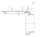
- Screw caps (300) are furthermore known, shown in Figures 3 and 4 , provided with a body (301) screwable on a threaded end of a container and of a closing part (302) connected to the body by means of a hinge element (303).
- Each of FR 2.215.361 and GB 2 164 028 discloses a cap as in the preamble of claim 1.
- An object of the invention is to improve known pressure caps.
- Another object of the invention is to obtain pressure caps that can be opened easily.
- a further object of the invention is to obtain pressure caps that are easily reclosable after a first opening.
- a still further object of the invention is to obtain caps provided with a hinge interposed between a closing part and a fixing part fixing to a container that can be manufactured without the use of complex moulds.
- a still further object of the invention is to obtain pressure caps that can be associated with usual threaded necks of containers.
- a still further object is to obtain containers that are particularly suitable for being shut with pressure caps.
- a pressure cap comprising a closure part associable with an opening of a container, engaging means associable with a neck of said container, said engaging means being provided with retaining means for engaging a projection of said container, a line of intended opening in said engaging means interposed between a side body of said engaging means and said closing part, said line of intended opening being defined by fracturable means, characterised in that said line of intended opening and said closing part are positioned in relation to one another so that said fracturable means break along said line of intended opening when said closing part is induced to detach itself from said side body.
- a first type consisting of easily openable caps, but devoid of opening indicating means
- a second type consisting of caps provided with opening indicating means but which are complicated to open.
- the fracturable means when the first opening of the container occurs the fracturable means is substantially fractured simultaneously to the removal of the closing part. It is not therefore necessary to perform two distinct operations, a first breaking operation of the fracturable elements and a second removing operation of the closing part.
- a screw cap comprising a side body screwable on a neck of a container and a closing part associable with an opening of said container, characterised in that it furthermore comprises a line of intended opening arranged substantially at the interface between said side body and said closing part.
- the closing part can define a pressure closing element associated with an opening of the container.
- a pressure closing element associated with an opening of the container.
- a method for opening a screw cap comprising a side body screwable on a neck of a container, a closing part associable with an opening of said container and a line of intended opening defined by fracturable means and arranged substantially at the interface between said side body and said closing part, comprising screwing said side body onto said neck so that an edge of said neck interacts with said closing part to break said fracturable means along said line of intended opening.
- a screw cap comprising a side body screwable on a neck of a container and a closing part associable with an opening of said container, characterised in that it furthermore comprises unscrewing promoting means arranged for partially unscrewing said side body from said neck after a first opening of said cap.
- the unscrewing promoting means partially unscrews the side body from the neck so as to position the side body suitably with respect to the neck.
- the unscrewing promoting means positions the side body so that the closing part, by rotating around the hinge, can engage the neck correctly for enabling the container to be closed again after a first opening.
- a cap comprising a side body associable with a neck of a container, a closing part associable with an opening of said container and a line of intended opening interposed between said side body and said closing part, characterised in that it furthermore comprises a wall thickening on said line of intended opening so as form hinge means that connect said side body and said closing part.
- the portion of the line of intended opening that is not affected by the wall thickening fractures, whereas the wall thickening, owing to the greater section, is not fractured and defines the hinge means around which the closing part can rotate in relation to the side body to enable the dispensing of a product contained in the container.
- a container comprising a neck provided with a dispensing end having a transverse dimension that is greater than the transverse dimension of a remaining part of neck, characterised in that the dispensing end comprises wall means having a substantially uniform thickness.
- a container comprising a neck provided with a dispensing end defined by wall means, characterised in that it furthermore comprises projection means extending from an intermediate portion of said wall means.
- a container comprising a neck provided with a dispensing end having a transverse dimension that is greater than the transverse dimension of a remaining part of neck, said dispensing end defining in said container a projection in which retaining means of a cap is engageable, characterised in that it furthermore comprises a further projection that cooperates with said projection to define seat means in which said retaining means is receivable.
- a combination of a cap comprising retaining means with a container comprising a neck provided with a dispensing end having a transverse dimension that is greater than the transverse dimension of a remaining part of neck is provided, said dispensing end defining in said container a projection in which said retaining means is engageable, and a further projection that cooperates with said projection to define seat means in which said retaining means is receivable.
- the further projection acts as a positioning element for preventing a move of the retaining means with respect to the container, so that the container can be easily closed after a first opening.
- a move of a side body of the container that is integral with the retaining means with respect to the neck could in fact prevent a closing part from engaging correctly with the neck.
- a container comprising a neck provided with an opening and with a projection projecting from said neck, said neck comprising wall means extending between said projection and said opening, characterised in that said wall means comprises a substantially smooth external surface.
- a method for producing a cap provided with a hinge comprising forming a side body of said cap, weakening said side body for obtaining a line of intended opening, characterised in that said weakening comprises obtaining in said side body, along said line of intended opening, a less weakened zone of a remaining part of said side body, said less weakened zone defining a hinge precursor.
- the method according to the invention does not therefore involve any additional complication with respect to the usual method of manufacture of the caps.
- a cap comprising a side body associable with a neck of a container, a closing part associable with an opening of said container and a line of intended opening defined by fracturable means and interposed between said side body and said closing part, characterised in that said fracturable means has non-uniform breaking resistance.
- a cap 1 is shown that is associable with a neck 2 of a container 3.
- the cap 1 can be made of plastic material, for example through injection or compression moulding of plastics.
- the container 3 comprises a substantially cylindrical first wall 4 and a substantially cylindrical second wall 5 arranged substantially coaxially, the second wall 5 having a diameter less than that of the first wall 4.
- the first wall 4 has a substantially constant thickness and defines a dispensing end of the container 3.
- annular wall 6 extends transversely to the latter that defines a collar 7.
- a variation of the container 3 is shown in which from the first wall 4 a projection 25 extends that is arranged for interacting with the cap 1, as will be disclosed in greater detail below.
- the projection 25 comprises a further annular wall 26 extending substantially perpendicular with respect to the first wall 4 and a tilted wall 27 interposed between the further annular wall 26 and the first wall 4.
- FIG. 14 Another variation of the container 3 is shown comprising a side wall 28 from which a projection element 29 projects, nearer an opening 30 of the container 3, and a second projection element 31, further away from the opening 30.
- the side wall 28 comprises a first substantially cylindrical portion 32, interposed between the first projection element 29 and the opening 30, and a second substantially cylindrical portion 33, interposed between the first projection 29 and the second projection element 31.
- the first portion 32 comprises a substantially smooth external surface 34.
- the first portion 32 and the second portion 33 can have a substantially constant thickness.
- first portion 32 and the second portion 33 are shaped so that the container 3 is provided with a dispensing end 35 having a substantially constant inner diameter.
- the cap 1 comprises a closing part 8 removably associable with the opening 30 and engaging means 10 provided with retaining means 11, provided with a hook-shaped end, that engages the collar 7.
- the engaging means 10 comprises a side body 12 having a first end 13 from which the retaining means 11 projects and a second end 14, opposite the first end 13, at which a line of intended opening 15 is provided extending between the side body 12 and the closing part 8.
- the line of intended opening 15 is defined by a plurality of fracturable elements 16 that connect the closing part 8 to the side body 12, between adjacent fracturable elements 16 there being interposed a weakened zone, for example a through cut 17.
- the engaging means 10 owing to the retaining means 11 that prevents the cap 1 from being able to be removed from the container without breakage of the fracturable elements 16 occurring, acts like an antitamper ring that assures the integrity of the cap 1.
- the closing part 8 comprises closing means 18 provided with an annular appendage 19 that projects from a face 23 of the closing part 8 to be received inside the first wall 4.
- the annular appendage 19 is shaped so as to interact with interference with an internal surface 20 of the first wall 4.
- the closing means 18 enables a seal to be achieved between the closing part 8 and the neck 2.
- Closing means comprising the annular appendage 19 is also provided in the embodiments of the cap 1 shown in the Figures 8 and from 10 to 14.
- the embodiment of the cap 1 shown in Figure 7 is provided with a closing part 8 provided with closing means 18 comprising a further annular appendage 21 that projects from the face 23 for surrounding the first wall 4.
- the further annular appendage 21 is shaped so as interact with interference with a substantially smooth external surface 22 of the first wall 4.
- the further annular appendage 21 comprises a groove 65 arranged for receiving in a shapingly formed manner a fashioned edge 66 extending from the external surface 22.
- the closing means 18 may comprise, instead of the annular appendage 19, or of the further annular appendage 21, substantially annular and circumferentially fragmentary bodies, defined, for example, by a plurality of protruding elements extending from the face 23.
- the cap 1 may comprise a hinge 36 that connects the closing part 8 to the engaging means 10, so as to enable the cap 1 to be closed again after a first opening.
- the hinge 36 may comprise a portion of the plastic material with which the cap 1 is made.
- the hinge 36 can be obtained in different ways, which will be illustrated below.
- the caps are obtained through injection or compression moulding of plastics.
- each cap comprises a continuous side wall, i.e. devoid of a line of intended opening.
- the cap comprises a closing part that is connected to respective engaging means without a line of intended opening being defined between the closing part and a side body.
- the line of intended opening is preferably but not necessarily obtained in the course of a subsequent step of the production cycle by making weakening between the closing part and the side body.
- This weakening can be obtained by making, using a suitable tool, a fragmentary cut - possibly a through cut - through the side wall of the cap. In this way fracturable elements are obtained having a thickness, radially measured, that is substantially the same as the initial thickness of the side wall.
- the weakening can be obtained by crushing the side wall so as to reduce the section thereof to promote breakage during first opening of the cap.
- the cap may comprise ribs distributed circumferentially on the side wall.
- the weakening can be obtained by making a cut that traverses, possibly completely, the entire thickness of the side wall but which does not substantially cut the ribs.
- the ribs form fracturable elements arranged for being fractured during first opening of the cap.
- the engaging means 10 may comprise a wall thickening 37 that forms the hinge 36 and a plurality of ribs 38 arranged for forming the fracturable elements 16.
- the ribs 38 project inside the cap 1.
- the ribs can project outside the cap 1.
- the engaging means 10 is made to interact with a tool that makes a cut that cuts the entire circumferal extent of the engaging means 10.
- the cut weakens the engaging means 10, for example by completely traversing the latter or extending for a substantial part of the thickness thereof, but does not completely traverse the wall thickening 37, or the ribs 38.
- the fracturable elements 16 are fractured whereas the thickening 37 that is provided with a greater section, and therefore with greater resistance to breakage, does not break but is deformed, giving rise to the hinge 16.
- the moulds can in fact easily be designed with a geometry that is such as to enable the wall thickening 37 to be obtained in the caps.
- the caps provided with hinges are thus obtained without increased costs or complications to the productive cycle, inasmuch as the wall thickening is obtained directly in the moulding step.
- the closing part 8 comprises opening promoting means 39 arranged at a zone of the closing part 8 substantially opposite the thickening 37.
- the ribs 38 have a growing circumferal extent proceeding from the opening promoting means 39 to the thickening 37.
- fracturable elements 16 are obtained having a section and therefore a resistance to fracturing that is variable.
- first ribs 38a, second ribs 38b and third ribs 38c are provided having gradually increasing circumferal extents.
- the first ribs 38a which are those having a lesser circumferal extent, can be easily fractured by a user who acts on the opening promoting means 39.
- the user can fracture the second ribs 38b and the third ribs 38c easily, although the second ribs 38b and the third ribs 38c have greater resistance to breakage than the first ribs 38a.
- a cap is obtained the fracturable elements of which have significant resistance, when the cap is applied to a container, to ensure a hermetic seal, even if inside the container the pressure differs with respect to the pressure outside the latter, as occurs in the case of containers filled with gassy drinks.
- the fracturable elements can easily be broken to ensure good inviolability and to facilitate opening by the consumer.
- a cap is shown provided with the wall thickening 37 and with fracturable elements 16a, 16b and 16c having variable circumferal extents.
- the fracturable elements 16 are obtained by cutting, for example with a through cut, the engaging means 10 using a suitably fashioned tool, in particular a tool provided with a fragmentary blade, or anyway provided with a discontinuity, at least at the fracturable elements 16, and possibly also the thickening 37.
- a cap is shown that is not provided with the wall thickening 37.
- a hinge precursor 24 and the fracturable elements 16 are obtained by making a cut, possibly a through cut, through the engaging means 10, this cut not affecting zones of the engaging means 11 in which the fracturable elements 16 and the hinge precursor 24 have to be defined.
- a cap 1 is shown provided with a thickening 37 that projects outside the engaging means 10.
- the fracturable elements 36 are obtained by using a tool shaped so as not to interact with the thickening 37.
- a cap 1 is shown provided with a line of intended opening 15 made by crushing the engaging means 10 so as to cause a decrease in the section thereof to promote breakage at the line of intended opening 15.
- the crushing can be irregular so as to obtain engaging means provided with a lesser thickness at a zone nearer the opening promoting means 39 and a larger thickness at a zone that is more distant from the opening promoting means 39.
- a cap 1 to be obtained comprising a fracturable part provided with limited resistance to breakage in an initial step of a first opening of the cap.
- irregular crushing has a similar effect to that obtained by providing fracturable elements having variable circumferal extents.
- the moulding mould can be shaped so as to mould engaging means 10 having an irregular thickness.
- a cap 1 is shown provided with engaging means 10 the side body 12 of which is shaped as a frustoconical wall, the diameter of the side body 12 decreasing proceeding from the closing part 8 to the retaining means 11.
- the cap 1 comprises positioning means 40 arranged for substantially preventing a movement of the engaging means 10 with respect to the neck 2, particularly after a first opening of the cap 1.
- the positioning means 40 enables the cap to be easily closed again after a first opening.
- the positioning means 40 comprises an arresting element 59 provided at an end of the retaining means 11 and arranged for being supportingly received on a further collar 9 that protrudes from neck 2.
- the collar 7 and the further collar 9 define a cavity 62 in which the hook-shaped portion of the retaining means 11 is received.
- the cavity can be delimited below by a convex part of the container 3.
- a container 3 is shown in which the cavity 62 is defined by the collar 7 and by an enlargement 63 extending above the projection 7 and connected to it by a connecting wall 64 extending substantially perpendicularly to the collar 7.
- the positioning means 40 comprises shoulder means 41 extending inside the cap 1 so as be interposed between the retaining means 11 and the line of intended opening 15.
- the retaining means 11 and the shoulder means 41 are shaped so as to surround the projection 25.
- the positioning means 40 comprises abutting means 42 arranged for interacting with the neck 2.
- the abutting means 42 comprises portions 43 of the ribs 38 associated with the side body 12 and supportingly received on the projection 25.
- the abutting means 42 comprises an abutting element 45, with which the engaging means 10 is provided, that interacts with an end zone 44 of the neck 2.
- the side body 12 comprises a first annular body 46, that surrounds the first wall 4, and a second annular body 47 having a smaller dimension than that of the first annular body 46.
- the abutting element 45 comprises a portion of tilted wall that connects the first annular body 46 to the second annular body 47.
- the line of intended opening 15 extends between the second annular body 47 and the closing part 8.
- the abutting means 42 comprises a ring 48 provided at an end of the engaging means 10 and arranged for interacting with an upper edge 49 of the neck 2.
- the ring 48 also acts as a seal element for preventing part of the contents of the container 3 from penetrating and possibly partially remaining in a gap defined between the neck 3 and the side body 12.
- a cap 1 comprising engaging means 10 provided with a side body 12 provided with a thread 55 arranged for engaging a further thread 56 obtained on a neck 2 of a container 3.
- the neck 2 furthermore comprises projection means 57, that cooperates with retaining means 11 with which the engaging means 10 is provided, and collar means 58.
- the cap 1 furthermore comprises a closing part 8, between the closing part 8 and the side body 12 a line of intended opening 15 being provided.
- the cap is openable with remarkable simplicity, possibly using a sole hand.
- the closing part 8 can be provided with an annular appendage 19 - or with a further annular appendage 21, similarly to what was disclosed with reference to Figures 7 and 9 - arranged to engage, respectively, an internal surface 20, or a substantially smooth external surface 22, of the neck 2.
- a hinge 36 that enables the cap 1 to be reclosed after a first opening.
- promoting means 39 is provided that is obtained in a zone of the closing part 8 substantially opposite a further zone in which the hinge 36 is obtained.
- the opening promoting means 39 comprises an activating surface 50, on which the user exerts a force, which can be obtained, for example, in an appendage 51 projecting from the closing part 8, as shown in Figure 21 , or in a recess 52 obtained in the closing part 8, as shown in Figure 23 .
- the activating surface 50 can peripherally affect the entire perimeter extent of the closing part 8.
- the annular appendage 19 can have a variable height, for example a decreasing height, by moving from the opening promoting means 39 to the hinge 36, so as to promote the insertion of the annular appendage inside the wall 4.
- the cap 1 furthermore comprises a further line of intended opening 53 interposed between the side body 12 and hooking means 11 with which the engaging means 10 is provided.
- the line of intended opening 15, the further line of intended opening 53 and the hinge 36 can be obtained with the methods disclosed with reference to Figures 5 to 19 .
- caps provided with the line of intended opening 15 can be obtained from the same semifinished product manufactured by moulding plastics.
- a manufacturer of caps can choose to weaken the side wall of the aforesaid semifinished product for obtaining the line of intended opening 15, if he is interested in manufacturing caps according to the invention, or can decide not to weaken the aforementioned side wall, obtaining in this way usual caps that are applicable to threaded necks.
- a method of cap production is provided that is very versatile, inasmuch as it enables a change from the production of caps of a certain type to caps of a different type to be made with extreme facility.
- the further line of intended opening 53 acts as an indicating element for indicating a possible opening of the container 3 achieved by unscrewing the side body 2 from the neck 3.
- a hood 71 is shown that is associable, for example by pressure, with the cap 1 so as to substantially cover the closing part 8.
- the hood 71 protects a part of the cap 1 from impurities that may come into direct contact with the mouth of a user.
- the hood 71 can easily be removed before opening of the cap 1.
- cap embodiment specified in Figure 14 can be equipped with a hood 71.
- a container 3 After being filled with a product, is closed with a cap 1, which is screwed onto the neck 3 by a capping head.
- An opening mode of the cap according to the invention may consist of further screwing of the cap 1 onto the neck 2, which makes an edge 44 of the neck 2 interact with the closing part 8, so as to break fracturable elements 36 that define the line of intended opening 15 and to remove the closing part 8 from the neck 2.
- a cap 1 comprising unscrewing promoting means 67 arranged for partially unscrewing the side body 12 from the neck 2 after a first opening of the cap 1, for example carried out through the method disclosed above.
- the unscrewing promoting means 67 acts as a positioning means that positions the side body 12 so that the closing part 8, by rotating around the hinge 36, can correctly engage the neck 2 to enable the container 3 to be closed again after a first opening.
- the unscrewing promoting means 67 comprises resilient means 68, for example an appendage 69 of the side body 12, shaped so as to interact with activating means 70 associated with the neck 2.
- antiscrewing means 54 is provided for.
- the antiscrewing means 54 also acts as positioning means that prevents a movement of the side body 12 with respect to the neck 2, to enable the cap 1 to be able to be closed again easily after a first opening.
- the antiscrewing means 54 comprises portions 43 of ribs 38 that define the fracturable elements 36 of the line of intended opening 15.
- the portions 43 are supportingly received on the further thread 56.
- the antiscrewing means 54 comprises a ring 48 provided at an end of the side body 12 and arranged for being supportingly received on an upper edge 49 of the neck 2.
- the side body 12 prevents portions of a product contained in the container 3 from penetrating a gap defined between the side body 12 and the neck 2.
- the antiscrewing means 54 comprises shoulder means 41 arranged for interacting with the projection means 57, so that the latter is received between the shoulder means 41 and the retaining means 11.
- the antiscrewing means 54 comprises an arresting element 59 associated with the thread 55 and arranged for interacting with the further thread 56 for arresting the screwing of the side body 12 on the neck 2.
- the ring 48 acts as a seal element to prevent part of the contents of the container 3 from penetrating and possibly stagnating in a gap defined between the neck 3 and the side body 12.
- the antiscrewing means 54 comprises a further arresting element 60 provided at an end 61 of the retaining means 11 and arranged for being supportingly received on the collar means 58.
Landscapes
- Engineering & Computer Science (AREA)
- Mechanical Engineering (AREA)
- Closures For Containers (AREA)
- Pharmaceuticals Containing Other Organic And Inorganic Compounds (AREA)
Priority Applications (1)
| Application Number | Priority Date | Filing Date | Title |
|---|---|---|---|
| EP10180371.6A EP2298660B1 (fr) | 2005-04-27 | 2006-04-26 | Bouchons pour récipients |
Applications Claiming Priority (2)
| Application Number | Priority Date | Filing Date | Title |
|---|---|---|---|
| IT000099A ITMO20050099A1 (it) | 2005-04-27 | 2005-04-27 | Capsule, contenitori e metodi. |
| EP06755841A EP1885612A2 (fr) | 2005-04-27 | 2006-04-26 | Bouchons, contenants et procedes |
Related Parent Applications (2)
| Application Number | Title | Priority Date | Filing Date |
|---|---|---|---|
| EP06755841A Division EP1885612A2 (fr) | 2005-04-27 | 2006-04-26 | Bouchons, contenants et procedes |
| EP06755841.1 Division | 2006-04-26 |
Related Child Applications (2)
| Application Number | Title | Priority Date | Filing Date |
|---|---|---|---|
| EP10180371.6A Division-Into EP2298660B1 (fr) | 2005-04-27 | 2006-04-26 | Bouchons pour récipients |
| EP10180371.6A Division EP2298660B1 (fr) | 2005-04-27 | 2006-04-26 | Bouchons pour récipients |
Publications (3)
| Publication Number | Publication Date |
|---|---|
| EP2138416A2 true EP2138416A2 (fr) | 2009-12-30 |
| EP2138416A3 EP2138416A3 (fr) | 2010-03-17 |
| EP2138416B1 EP2138416B1 (fr) | 2011-11-30 |
Family
ID=36928365
Family Applications (3)
| Application Number | Title | Priority Date | Filing Date |
|---|---|---|---|
| EP09151135A Active EP2138416B1 (fr) | 2005-04-27 | 2006-04-26 | Capuchon |
| EP06755841A Withdrawn EP1885612A2 (fr) | 2005-04-27 | 2006-04-26 | Bouchons, contenants et procedes |
| EP10180371.6A Active EP2298660B1 (fr) | 2005-04-27 | 2006-04-26 | Bouchons pour récipients |
Family Applications After (2)
| Application Number | Title | Priority Date | Filing Date |
|---|---|---|---|
| EP06755841A Withdrawn EP1885612A2 (fr) | 2005-04-27 | 2006-04-26 | Bouchons, contenants et procedes |
| EP10180371.6A Active EP2298660B1 (fr) | 2005-04-27 | 2006-04-26 | Bouchons pour récipients |
Country Status (10)
| Country | Link |
|---|---|
| US (1) | US8424697B2 (fr) |
| EP (3) | EP2138416B1 (fr) |
| JP (1) | JP2008539135A (fr) |
| CN (2) | CN102815448B (fr) |
| AT (1) | ATE535461T1 (fr) |
| BR (1) | BRPI0610767B1 (fr) |
| ES (2) | ES2523746T3 (fr) |
| IT (1) | ITMO20050099A1 (fr) |
| MX (2) | MX351936B (fr) |
| WO (1) | WO2006114697A2 (fr) |
Families Citing this family (8)
| Publication number | Priority date | Publication date | Assignee | Title |
|---|---|---|---|---|
| FR2954935B1 (fr) * | 2010-01-06 | 2012-04-20 | Hema | Procede et dispositif de traitement de recipients |
| ITMO20130242A1 (it) * | 2013-08-29 | 2015-03-01 | Ativa | Capsula di sicurezza per contenitori. |
| KR101581161B1 (ko) * | 2015-05-28 | 2015-12-30 | 김장식 | 용기뚜껑 |
| US10155609B2 (en) * | 2017-03-23 | 2018-12-18 | Bway Corporation | Tamper evident tub |
| CN108100446A (zh) * | 2018-01-23 | 2018-06-01 | 浙江亿隆包装有限公司 | 一种奶粉盖 |
| WO2019165529A1 (fr) * | 2018-03-01 | 2019-09-06 | MARTINS, Andrea Luciana | Dispositif d'ouverture automatique d'un récipient pourvu de moyens pour la rupture d'un élément de fermeture hermétique d'un récipient |
| MX2021001855A (es) | 2018-09-09 | 2021-05-13 | Novembal Usa Inc | Tapon de plastico sujetado. |
| IT201900018737A1 (it) * | 2019-10-14 | 2021-04-14 | Sacmi | Tappo per un contenitore |
Citations (2)
| Publication number | Priority date | Publication date | Assignee | Title |
|---|---|---|---|---|
| FR2215361A1 (en) | 1973-01-26 | 1974-08-23 | Dale Ltd John | Polyethylene tamper-proof container - has tear strips securing closure to container |
| GB2164028A (en) | 1984-09-05 | 1986-03-12 | Asepta Ag | Container with a flexible lid |
Family Cites Families (29)
| Publication number | Priority date | Publication date | Assignee | Title |
|---|---|---|---|---|
| US3908855A (en) * | 1972-07-18 | 1975-09-30 | Dorn Co V | Bail receiver for plastic containers |
| BE810244A (fr) * | 1973-01-26 | 1974-05-16 | Combinaison de recipient et de fermeture | |
| US4126244A (en) * | 1977-08-30 | 1978-11-21 | Owens-Illinois, Inc. | Container component with easy-opening wall section |
| FR2499519A1 (fr) * | 1981-02-11 | 1982-08-13 | Grussen Jean | Capsule de bouchage a vis avec anneau d'inviolabilite |
| DE3346928A1 (de) * | 1983-12-24 | 1985-07-04 | Friedrich Sanner GmbH & Co KG Spritzgußwerk, 6140 Bensheim | Originalitaetsgesicherte verschlussanordnung |
| JPH0344659Y2 (fr) * | 1984-12-20 | 1991-09-19 | ||
| JPH033491Y2 (fr) * | 1985-05-10 | 1991-01-29 | ||
| JPH0610017B2 (ja) * | 1986-05-22 | 1994-02-09 | 日本クラウンコルク株式会社 | 合成樹脂製容器蓋 |
| JPH0547086Y2 (fr) * | 1988-10-13 | 1993-12-10 | ||
| JPH0725318Y2 (ja) * | 1989-04-17 | 1995-06-07 | 株式会社柴崎製作所 | 防爆キャップ |
| JPH03648A (ja) * | 1989-05-29 | 1991-01-07 | Johnsen & Jorgensen Plast Ltd | 容器の閉蓋具 |
| JP2526433Y2 (ja) * | 1990-12-26 | 1997-02-19 | 株式会社柴崎製作所 | 合成樹脂製キャップ |
| JP2619999B2 (ja) | 1991-08-19 | 1997-06-11 | 松下電器産業株式会社 | 磁気記録再生装置 |
| FR2719559B1 (fr) * | 1994-05-06 | 1996-07-26 | Rical Sa | Capsule de bouchage pour un récipient ayant un col à collerette d'accrochage unique. |
| TW338413U (en) * | 1994-05-17 | 1998-08-11 | Mikasa Industry Co Ltd | Closing device of a container |
| US5944207A (en) * | 1995-10-30 | 1999-08-31 | Reidenbach; Bryan L. | Bottle closure assembly |
| JP3764994B2 (ja) * | 1996-03-19 | 2006-04-12 | 三笠産業株式会社 | 容器の開閉装置 |
| US5915601A (en) * | 1996-12-06 | 1999-06-29 | Phoenix Closures, Inc. | Scored dispensing liner |
| CN2360358Y (zh) * | 1998-12-05 | 2000-01-26 | 深圳市聚德实业发展有限公司 | 具有防伪功能的饮料瓶 |
| US7059485B1 (en) * | 1999-06-03 | 2006-06-13 | Reidenbach Bryan L | Tamper-resistant bottle closure |
| JP2001088857A (ja) * | 1999-09-17 | 2001-04-03 | Dainippon Printing Co Ltd | フィルムインサート注出口 |
| DE20003011U1 (de) * | 2000-02-18 | 2000-07-13 | Bergi Plast Gmbh Kunststofftec | Schutzkappe |
| JP4447733B2 (ja) * | 2000-05-11 | 2010-04-07 | 日本クラウンコルク株式会社 | キャップ |
| US6474490B1 (en) * | 2000-11-10 | 2002-11-05 | Label Makers, Inc. | Combined container cap and lift tab opener |
| US20030051440A1 (en) * | 2001-09-13 | 2003-03-20 | Preco Laser Systems, Llc | Method of creating easy-open load carrying bags |
| US6726043B2 (en) * | 2001-10-04 | 2004-04-27 | Coors Global Properties, Inc. | Container and plastic threadless closure member |
| JP4560320B2 (ja) * | 2004-03-30 | 2010-10-13 | 日本クラウンコルク株式会社 | 開口形成用スコア付プラスチックキャップ |
| US7832580B2 (en) * | 2004-09-13 | 2010-11-16 | Brian Francis Jackman | Tamper evident container seal with integral pull opener |
| US7303088B2 (en) * | 2005-03-11 | 2007-12-04 | Berry Plastics Corporation | Tamper-evident closure |
-
2005
- 2005-04-27 IT IT000099A patent/ITMO20050099A1/it unknown
-
2006
- 2006-04-26 MX MX2011008812A patent/MX351936B/es unknown
- 2006-04-26 CN CN201210298134.7A patent/CN102815448B/zh active Active
- 2006-04-26 EP EP09151135A patent/EP2138416B1/fr active Active
- 2006-04-26 BR BRPI0610767A patent/BRPI0610767B1/pt active IP Right Grant
- 2006-04-26 US US11/919,335 patent/US8424697B2/en active Active
- 2006-04-26 EP EP06755841A patent/EP1885612A2/fr not_active Withdrawn
- 2006-04-26 EP EP10180371.6A patent/EP2298660B1/fr active Active
- 2006-04-26 ES ES10180371.6T patent/ES2523746T3/es active Active
- 2006-04-26 WO PCT/IB2006/001020 patent/WO2006114697A2/fr active Application Filing
- 2006-04-26 ES ES09151135T patent/ES2379432T3/es active Active
- 2006-04-26 JP JP2008508325A patent/JP2008539135A/ja active Pending
- 2006-04-26 AT AT09151135T patent/ATE535461T1/de active
- 2006-04-26 CN CN200680020068XA patent/CN101208243B/zh active Active
- 2006-04-26 MX MX2007013546A patent/MX2007013546A/es unknown
Patent Citations (2)
| Publication number | Priority date | Publication date | Assignee | Title |
|---|---|---|---|---|
| FR2215361A1 (en) | 1973-01-26 | 1974-08-23 | Dale Ltd John | Polyethylene tamper-proof container - has tear strips securing closure to container |
| GB2164028A (en) | 1984-09-05 | 1986-03-12 | Asepta Ag | Container with a flexible lid |
Also Published As
| Publication number | Publication date |
|---|---|
| BRPI0610767B1 (pt) | 2018-11-06 |
| EP2138416B1 (fr) | 2011-11-30 |
| MX2007013546A (es) | 2008-04-04 |
| EP1885612A2 (fr) | 2008-02-13 |
| CN102815448B (zh) | 2015-08-26 |
| WO2006114697A3 (fr) | 2007-03-01 |
| CN101208243A (zh) | 2008-06-25 |
| ES2379432T3 (es) | 2012-04-26 |
| CN102815448A (zh) | 2012-12-12 |
| ITMO20050099A1 (it) | 2006-10-28 |
| BRPI0610767A2 (pt) | 2011-02-22 |
| WO2006114697A2 (fr) | 2006-11-02 |
| US8424697B2 (en) | 2013-04-23 |
| US20090314776A1 (en) | 2009-12-24 |
| EP2138416A3 (fr) | 2010-03-17 |
| ES2523746T3 (es) | 2014-12-01 |
| EP2298660A1 (fr) | 2011-03-23 |
| ATE535461T1 (de) | 2011-12-15 |
| CN101208243B (zh) | 2012-10-03 |
| JP2008539135A (ja) | 2008-11-13 |
| MX351936B (es) | 2017-11-01 |
| EP2298660B1 (fr) | 2014-08-20 |
Similar Documents
| Publication | Publication Date | Title |
|---|---|---|
| EP2138416B1 (fr) | Capuchon | |
| CA2501327C (fr) | Capsule de bouteille inviolable | |
| US7281638B2 (en) | Snap-hinge closure with tamper-evident lid and method of making | |
| US4494664A (en) | Tamper evident closure | |
| EP3877281B1 (fr) | Capuchon pour récipient, combinaison d'un capuchon et d'un col du récipient et son procédé de production | |
| JP5877557B2 (ja) | 合成樹脂製ヒンジキャップ | |
| CN113631485B (zh) | 用于封闭容器的盖子以及盖子和颈部的组合 | |
| WO2007085896A9 (fr) | Dispositif de fermeture | |
| CN114007952B (zh) | 用于封闭容器的盖子以及用于制造盖子的方法 | |
| EP4001157B1 (fr) | Bouchon de fermeture d'un récipient, combinaison d'un bouchon et d'un goulot | |
| US20040011757A1 (en) | Screw cap of synthetic resin | |
| CN114007948A (zh) | 用于容器的盖、以及盖和容器颈部的组合 | |
| CN109153479B (zh) | 包括显窃启装置的容器盖 | |
| EP3532399A1 (fr) | Fermeture à tirette pour récipients | |
| CN113924257A (zh) | 用于容器的封闭盖及其制造方法 | |
| EP1796980B1 (fr) | Bouchon pour contenants | |
| EP2380820B1 (fr) | Ensemble de fermeture | |
| US20060043053A1 (en) | Tamper-evident plug seal closure | |
| AU2008264964B2 (en) | Closure system and its method of forming | |
| JP5889011B2 (ja) | 封緘付きネジキャップの成形金型 | |
| AU2008351584B2 (en) | Closure | |
| EP2088090A1 (fr) | Capuchon de fermeture anti-sabotage et combinaison de fermeture et de récipient | |
| JP4634994B2 (ja) | 合成樹脂製容器蓋 | |
| JP2002274558A (ja) | 分別廃棄可能なキャップ | |
| RU78474U1 (ru) | Устройство для укупоривания бутылки |
Legal Events
| Date | Code | Title | Description |
|---|---|---|---|
| PUAI | Public reference made under article 153(3) epc to a published international application that has entered the european phase |
Free format text: ORIGINAL CODE: 0009012 |
|
| AC | Divisional application: reference to earlier application |
Ref document number: 1885612 Country of ref document: EP Kind code of ref document: P |
|
| AK | Designated contracting states |
Kind code of ref document: A2 Designated state(s): AT BE BG CH CY CZ DE DK EE ES FI FR GB GR HU IE IS IT LI LT LU LV MC NL PL PT RO SE SI SK TR |
|
| PUAL | Search report despatched |
Free format text: ORIGINAL CODE: 0009013 |
|
| AK | Designated contracting states |
Kind code of ref document: A3 Designated state(s): AT BE BG CH CY CZ DE DK EE ES FI FR GB GR HU IE IS IT LI LT LU LV MC NL PL PT RO SE SI SK TR |
|
| 17P | Request for examination filed |
Effective date: 20100909 |
|
| AKX | Designation fees paid |
Designated state(s): AT BE BG CH CY CZ DE DK EE ES FI FR GB GR HU IE IS IT LI LT LU LV MC NL PL PT RO SE SI SK TR |
|
| RTI1 | Title (correction) |
Free format text: CAPS |
|
| GRAP | Despatch of communication of intention to grant a patent |
Free format text: ORIGINAL CODE: EPIDOSNIGR1 |
|
| RIN1 | Information on inventor provided before grant (corrected) |
Inventor name: PUCCI, FABRIZIO |
|
| GRAS | Grant fee paid |
Free format text: ORIGINAL CODE: EPIDOSNIGR3 |
|
| GRAA | (expected) grant |
Free format text: ORIGINAL CODE: 0009210 |
|
| AC | Divisional application: reference to earlier application |
Ref document number: 1885612 Country of ref document: EP Kind code of ref document: P |
|
| AK | Designated contracting states |
Kind code of ref document: B1 Designated state(s): AT BE BG CH CY CZ DE DK EE ES FI FR GB GR HU IE IS IT LI LT LU LV MC NL PL PT RO SE SI SK TR |
|
| RAP1 | Party data changed (applicant data changed or rights of an application transferred) |
Owner name: SACMI COOPERATIVA MECCANICI IMOLA SOCIETA' COOPERA |
|
| REG | Reference to a national code |
Ref country code: GB Ref legal event code: FG4D Ref country code: CH Ref legal event code: EP |
|
| REG | Reference to a national code |
Ref country code: IE Ref legal event code: FG4D |
|
| RAP2 | Party data changed (patent owner data changed or rights of a patent transferred) |
Owner name: SACMI COOPERATIVA MECCANICI IMOLA SOCIETA' COOPERA |
|
| REG | Reference to a national code |
Ref country code: DE Ref legal event code: R096 Ref document number: 602006026226 Country of ref document: DE Effective date: 20120216 |
|
| REG | Reference to a national code |
Ref country code: NL Ref legal event code: T3 |
|
| REG | Reference to a national code |
Ref country code: CH Ref legal event code: NV Representative=s name: FIAMMENGHI-FIAMMENGHI |
|
| LTIE | Lt: invalidation of european patent or patent extension |
Effective date: 20111130 |
|
| REG | Reference to a national code |
Ref country code: ES Ref legal event code: FG2A Ref document number: 2379432 Country of ref document: ES Kind code of ref document: T3 Effective date: 20120426 |
|
| PG25 | Lapsed in a contracting state [announced via postgrant information from national office to epo] |
Ref country code: LT Free format text: LAPSE BECAUSE OF FAILURE TO SUBMIT A TRANSLATION OF THE DESCRIPTION OR TO PAY THE FEE WITHIN THE PRESCRIBED TIME-LIMIT Effective date: 20111130 Ref country code: IS Free format text: LAPSE BECAUSE OF FAILURE TO SUBMIT A TRANSLATION OF THE DESCRIPTION OR TO PAY THE FEE WITHIN THE PRESCRIBED TIME-LIMIT Effective date: 20120330 |
|
| PG25 | Lapsed in a contracting state [announced via postgrant information from national office to epo] |
Ref country code: PT Free format text: LAPSE BECAUSE OF FAILURE TO SUBMIT A TRANSLATION OF THE DESCRIPTION OR TO PAY THE FEE WITHIN THE PRESCRIBED TIME-LIMIT Effective date: 20120330 Ref country code: GR Free format text: LAPSE BECAUSE OF FAILURE TO SUBMIT A TRANSLATION OF THE DESCRIPTION OR TO PAY THE FEE WITHIN THE PRESCRIBED TIME-LIMIT Effective date: 20120301 Ref country code: LV Free format text: LAPSE BECAUSE OF FAILURE TO SUBMIT A TRANSLATION OF THE DESCRIPTION OR TO PAY THE FEE WITHIN THE PRESCRIBED TIME-LIMIT Effective date: 20111130 Ref country code: SE Free format text: LAPSE BECAUSE OF FAILURE TO SUBMIT A TRANSLATION OF THE DESCRIPTION OR TO PAY THE FEE WITHIN THE PRESCRIBED TIME-LIMIT Effective date: 20111130 Ref country code: SI Free format text: LAPSE BECAUSE OF FAILURE TO SUBMIT A TRANSLATION OF THE DESCRIPTION OR TO PAY THE FEE WITHIN THE PRESCRIBED TIME-LIMIT Effective date: 20111130 |
|
| PG25 | Lapsed in a contracting state [announced via postgrant information from national office to epo] |
Ref country code: CY Free format text: LAPSE BECAUSE OF FAILURE TO SUBMIT A TRANSLATION OF THE DESCRIPTION OR TO PAY THE FEE WITHIN THE PRESCRIBED TIME-LIMIT Effective date: 20111130 |
|
| PG25 | Lapsed in a contracting state [announced via postgrant information from national office to epo] |
Ref country code: EE Free format text: LAPSE BECAUSE OF FAILURE TO SUBMIT A TRANSLATION OF THE DESCRIPTION OR TO PAY THE FEE WITHIN THE PRESCRIBED TIME-LIMIT Effective date: 20111130 Ref country code: CZ Free format text: LAPSE BECAUSE OF FAILURE TO SUBMIT A TRANSLATION OF THE DESCRIPTION OR TO PAY THE FEE WITHIN THE PRESCRIBED TIME-LIMIT Effective date: 20111130 Ref country code: DK Free format text: LAPSE BECAUSE OF FAILURE TO SUBMIT A TRANSLATION OF THE DESCRIPTION OR TO PAY THE FEE WITHIN THE PRESCRIBED TIME-LIMIT Effective date: 20111130 Ref country code: BG Free format text: LAPSE BECAUSE OF FAILURE TO SUBMIT A TRANSLATION OF THE DESCRIPTION OR TO PAY THE FEE WITHIN THE PRESCRIBED TIME-LIMIT Effective date: 20120229 Ref country code: SK Free format text: LAPSE BECAUSE OF FAILURE TO SUBMIT A TRANSLATION OF THE DESCRIPTION OR TO PAY THE FEE WITHIN THE PRESCRIBED TIME-LIMIT Effective date: 20111130 |
|
| PG25 | Lapsed in a contracting state [announced via postgrant information from national office to epo] |
Ref country code: PL Free format text: LAPSE BECAUSE OF FAILURE TO SUBMIT A TRANSLATION OF THE DESCRIPTION OR TO PAY THE FEE WITHIN THE PRESCRIBED TIME-LIMIT Effective date: 20111130 Ref country code: RO Free format text: LAPSE BECAUSE OF FAILURE TO SUBMIT A TRANSLATION OF THE DESCRIPTION OR TO PAY THE FEE WITHIN THE PRESCRIBED TIME-LIMIT Effective date: 20111130 |
|
| PLBE | No opposition filed within time limit |
Free format text: ORIGINAL CODE: 0009261 |
|
| STAA | Information on the status of an ep patent application or granted ep patent |
Free format text: STATUS: NO OPPOSITION FILED WITHIN TIME LIMIT |
|
| 26N | No opposition filed |
Effective date: 20120831 |
|
| PG25 | Lapsed in a contracting state [announced via postgrant information from national office to epo] |
Ref country code: MC Free format text: LAPSE BECAUSE OF NON-PAYMENT OF DUE FEES Effective date: 20120430 |
|
| GBPC | Gb: european patent ceased through non-payment of renewal fee |
Effective date: 20120426 |
|
| REG | Reference to a national code |
Ref country code: DE Ref legal event code: R097 Ref document number: 602006026226 Country of ref document: DE Effective date: 20120831 |
|
| REG | Reference to a national code |
Ref country code: HU Ref legal event code: AG4A Ref document number: E014668 Country of ref document: HU |
|
| REG | Reference to a national code |
Ref country code: IE Ref legal event code: MM4A |
|
| PG25 | Lapsed in a contracting state [announced via postgrant information from national office to epo] |
Ref country code: GB Free format text: LAPSE BECAUSE OF NON-PAYMENT OF DUE FEES Effective date: 20120426 Ref country code: IE Free format text: LAPSE BECAUSE OF NON-PAYMENT OF DUE FEES Effective date: 20120426 |
|
| PG25 | Lapsed in a contracting state [announced via postgrant information from national office to epo] |
Ref country code: FI Free format text: LAPSE BECAUSE OF FAILURE TO SUBMIT A TRANSLATION OF THE DESCRIPTION OR TO PAY THE FEE WITHIN THE PRESCRIBED TIME-LIMIT Effective date: 20111130 |
|
| PGFP | Annual fee paid to national office [announced via postgrant information from national office to epo] |
Ref country code: NL Payment date: 20140320 Year of fee payment: 9 Ref country code: LU Payment date: 20140325 Year of fee payment: 9 |
|
| PGFP | Annual fee paid to national office [announced via postgrant information from national office to epo] |
Ref country code: BE Payment date: 20140328 Year of fee payment: 9 |
|
| PGFP | Annual fee paid to national office [announced via postgrant information from national office to epo] |
Ref country code: CH Payment date: 20150324 Year of fee payment: 10 |
|
| PGFP | Annual fee paid to national office [announced via postgrant information from national office to epo] |
Ref country code: TR Payment date: 20150421 Year of fee payment: 10 |
|
| PGFP | Annual fee paid to national office [announced via postgrant information from national office to epo] |
Ref country code: AT Payment date: 20150320 Year of fee payment: 10 Ref country code: HU Payment date: 20150528 Year of fee payment: 10 Ref country code: IT Payment date: 20150325 Year of fee payment: 10 |
|
| PG25 | Lapsed in a contracting state [announced via postgrant information from national office to epo] |
Ref country code: LU Free format text: LAPSE BECAUSE OF NON-PAYMENT OF DUE FEES Effective date: 20150426 |
|
| REG | Reference to a national code |
Ref country code: NL Ref legal event code: MM Effective date: 20150501 |
|
| REG | Reference to a national code |
Ref country code: FR Ref legal event code: PLFP Year of fee payment: 11 |
|
| PG25 | Lapsed in a contracting state [announced via postgrant information from national office to epo] |
Ref country code: NL Free format text: LAPSE BECAUSE OF NON-PAYMENT OF DUE FEES Effective date: 20150501 |
|
| REG | Reference to a national code |
Ref country code: CH Ref legal event code: PL |
|
| REG | Reference to a national code |
Ref country code: AT Ref legal event code: MM01 Ref document number: 535461 Country of ref document: AT Kind code of ref document: T Effective date: 20160426 |
|
| PG25 | Lapsed in a contracting state [announced via postgrant information from national office to epo] |
Ref country code: HU Free format text: LAPSE BECAUSE OF NON-PAYMENT OF DUE FEES Effective date: 20160427 Ref country code: LI Free format text: LAPSE BECAUSE OF NON-PAYMENT OF DUE FEES Effective date: 20160430 Ref country code: CH Free format text: LAPSE BECAUSE OF NON-PAYMENT OF DUE FEES Effective date: 20160430 |
|
| PG25 | Lapsed in a contracting state [announced via postgrant information from national office to epo] |
Ref country code: AT Free format text: LAPSE BECAUSE OF NON-PAYMENT OF DUE FEES Effective date: 20160426 Ref country code: IT Free format text: LAPSE BECAUSE OF NON-PAYMENT OF DUE FEES Effective date: 20160426 |
|
| REG | Reference to a national code |
Ref country code: FR Ref legal event code: PLFP Year of fee payment: 12 |
|
| PG25 | Lapsed in a contracting state [announced via postgrant information from national office to epo] |
Ref country code: BE Free format text: LAPSE BECAUSE OF NON-PAYMENT OF DUE FEES Effective date: 20150430 |
|
| REG | Reference to a national code |
Ref country code: FR Ref legal event code: PLFP Year of fee payment: 13 |
|
| PG25 | Lapsed in a contracting state [announced via postgrant information from national office to epo] |
Ref country code: TR Free format text: LAPSE BECAUSE OF NON-PAYMENT OF DUE FEES Effective date: 20160426 |
|
| PGFP | Annual fee paid to national office [announced via postgrant information from national office to epo] |
Ref country code: FR Payment date: 20230321 Year of fee payment: 18 |
|
| P01 | Opt-out of the competence of the unified patent court (upc) registered |
Effective date: 20230529 |
|
| PGFP | Annual fee paid to national office [announced via postgrant information from national office to epo] |
Ref country code: ES Payment date: 20230502 Year of fee payment: 18 Ref country code: DE Payment date: 20230321 Year of fee payment: 18 |