EP2136255A2 - Bilderzeugungsvorrichtung - Google Patents
Bilderzeugungsvorrichtung Download PDFInfo
- Publication number
- EP2136255A2 EP2136255A2 EP09162146A EP09162146A EP2136255A2 EP 2136255 A2 EP2136255 A2 EP 2136255A2 EP 09162146 A EP09162146 A EP 09162146A EP 09162146 A EP09162146 A EP 09162146A EP 2136255 A2 EP2136255 A2 EP 2136255A2
- Authority
- EP
- European Patent Office
- Prior art keywords
- count value
- unit
- section
- replacement
- life duration
- Prior art date
- Legal status (The legal status is an assumption and is not a legal conclusion. Google has not performed a legal analysis and makes no representation as to the accuracy of the status listed.)
- Withdrawn
Links
- 238000000034 method Methods 0.000 description 36
- 238000012423 maintenance Methods 0.000 description 31
- 238000012546 transfer Methods 0.000 description 26
- 238000004891 communication Methods 0.000 description 13
- 238000010586 diagram Methods 0.000 description 11
- 230000015556 catabolic process Effects 0.000 description 6
- 238000013500 data storage Methods 0.000 description 3
- 238000013459 approach Methods 0.000 description 2
- 238000004140 cleaning Methods 0.000 description 2
- 230000006870 function Effects 0.000 description 2
- 238000003825 pressing Methods 0.000 description 2
- 230000000712 assembly Effects 0.000 description 1
- 238000000429 assembly Methods 0.000 description 1
- 210000003323 beak Anatomy 0.000 description 1
- 230000005540 biological transmission Effects 0.000 description 1
- 238000006243 chemical reaction Methods 0.000 description 1
- 238000013461 design Methods 0.000 description 1
- 239000011521 glass Substances 0.000 description 1
- 238000010438 heat treatment Methods 0.000 description 1
- 238000005286 illumination Methods 0.000 description 1
- 238000003384 imaging method Methods 0.000 description 1
- 230000001788 irregular Effects 0.000 description 1
- 239000004973 liquid crystal related substance Substances 0.000 description 1
- 230000007774 longterm Effects 0.000 description 1
- 230000003287 optical effect Effects 0.000 description 1
- 238000012545 processing Methods 0.000 description 1
- 230000004044 response Effects 0.000 description 1
Images


Classifications
-
- G—PHYSICS
- G03—PHOTOGRAPHY; CINEMATOGRAPHY; ANALOGOUS TECHNIQUES USING WAVES OTHER THAN OPTICAL WAVES; ELECTROGRAPHY; HOLOGRAPHY
- G03G—ELECTROGRAPHY; ELECTROPHOTOGRAPHY; MAGNETOGRAPHY
- G03G15/00—Apparatus for electrographic processes using a charge pattern
- G03G15/50—Machine control of apparatus for electrographic processes using a charge pattern, e.g. regulating differents parts of the machine, multimode copiers, microprocessor control
- G03G15/5016—User-machine interface; Display panels; Control console
- G03G15/502—User-machine interface; Display panels; Control console relating to the structure of the control menu, e.g. pop-up menus, help screens
-
- G—PHYSICS
- G03—PHOTOGRAPHY; CINEMATOGRAPHY; ANALOGOUS TECHNIQUES USING WAVES OTHER THAN OPTICAL WAVES; ELECTROGRAPHY; HOLOGRAPHY
- G03G—ELECTROGRAPHY; ELECTROPHOTOGRAPHY; MAGNETOGRAPHY
- G03G15/00—Apparatus for electrographic processes using a charge pattern
- G03G15/50—Machine control of apparatus for electrographic processes using a charge pattern, e.g. regulating differents parts of the machine, multimode copiers, microprocessor control
- G03G15/5075—Remote control machines, e.g. by a host
- G03G15/5079—Remote control machines, e.g. by a host for maintenance
-
- G—PHYSICS
- G03—PHOTOGRAPHY; CINEMATOGRAPHY; ANALOGOUS TECHNIQUES USING WAVES OTHER THAN OPTICAL WAVES; ELECTROGRAPHY; HOLOGRAPHY
- G03G—ELECTROGRAPHY; ELECTROPHOTOGRAPHY; MAGNETOGRAPHY
- G03G15/00—Apparatus for electrographic processes using a charge pattern
- G03G15/55—Self-diagnostics; Malfunction or lifetime display
- G03G15/553—Monitoring or warning means for exhaustion or lifetime end of consumables, e.g. indication of insufficient copy sheet quantity for a job
-
- G—PHYSICS
- G03—PHOTOGRAPHY; CINEMATOGRAPHY; ANALOGOUS TECHNIQUES USING WAVES OTHER THAN OPTICAL WAVES; ELECTROGRAPHY; HOLOGRAPHY
- G03G—ELECTROGRAPHY; ELECTROPHOTOGRAPHY; MAGNETOGRAPHY
- G03G2215/00—Apparatus for electrophotographic processes
- G03G2215/00025—Machine control, e.g. regulating different parts of the machine
- G03G2215/00109—Remote control of apparatus, e.g. by a host
Definitions
- the present invention relates to an image forming apparatus.
- an image forming apparatus comprising a detachable unit in which a plurality of replaceable parts are grouped in one.
- an unit in which the part is installed is pulled out from the image forming apparatus and is replaced.
- the unit after the replacement is collected, and is reused by the part which reached its life duration or which broke down being replaced with a new part (for example, see JP 2005-107440 (hereinafter, called patent document 1)).
- an image forming apparatus with a design of improved replaceability of units.
- an image forming apparatus which measures life durations of parts of each unit and which urges a user to replace the unit by warning a user that it is a replacement time when the life duration approaches.
- a user pulls out the unit which has been warned from the image forming apparatus and replaces with a backup unit.
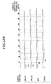
- FIGS. 11A and 11B a unit replacement time in a case where the conventional unit replacement which has been carried out by a service man at the time of routine maintenance is carried out by a user.
- the routine maintenance is carried out in a cycle of 2 million print cycle
- the replacement time (shown as MC in FIGS. 11A and 11B ) of the roller 1, the roller 2, the belt and the sleeve which are installed in the fixing unit are set to every 200,000 prints, every 200,000 prints, every 400,000 prints and every 600, 000 prints, respectively, according to the cycle of the routine maintenance in advance.
- 11A shows a case where break down of a part which is installed in the fixing unit has not occurred and where the unit replacement was carried out only at the time of routine maintenance, and the unit replacement is carried out at the time shown in dashed line.
- the number of times of the unit replacement up to 2 million prints is 10 times.
- a user replaces the whole unit and a service man collects the unit and carries out the part replacement of the replaced unit at a base.
- the apparatus When a user carries out the unit replacement, the apparatus itself manages the number of times each part is used (count value of number of sheets printed), determines whether each part reached the time where the part needs to be replaced or not based on the number of times each part is used. When the part reached the replacement time, the apparatus urges a user to replace the unit including the part and there is no room for a service's determination to intervene as in the conventional case. Therefore, for example, when the roller 1 breaks down and is replaced before reaching the 400,000 prints (for example, at the time of 370,000 prints) which is the next replacement time after the roller 1 is replaced once after reaching 200,000 prints as shown in FIG.
- An object of the present invention is to attempt to reduce the down time in the image forming apparatus by reducing the unit replacement frequency where a user carries out the unit replacement.
- an image forming apparatus comprises a replaceable unit in which a plurality of replaceable parts are installed, a storage section to store a replacement time count value showing a replacement time of each or the parts installed in the unit, a life duration time count value showing a life duration time of each of the parts and a use count value showing a number of times of use of each of the parts, a display section and a control section to update the use count value in the storage section by counting the number of times of use of each of the parts installed in the unit, to determine whether a part which reached the life duration time exists or not based on the use count value of each of the parts which are update and the life duration time count value, and to display information for urging a replacement of the part which reached the life duration time and a part in which the use count value reached between the replacement time count value and the life duration time count value in the display section when the control section determines that the part which reached the life duration time exists.
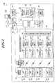
- the image forming apparatus 100 comprises a control section 10, an operation section 20, a scanner section 30, a communication section 40, a printer section 50, a reader/writer section 60 a power supply section 80 and the like.
- the control section 10 is constituted with a CPU (Central Processing Unit), a ROM (Read Only Memory), a RAM (Random Access Memory) and the like.
- Various types of process programs are stored in the ROM of the control section 10, and the CPU of the control section 10 reads the various types of programs stored in the ROM and expands the programs in the RAM and controls the operation of each part of the image forming apparatus 100 according to the expanded programs.
- the storage section 11 which is constituted with a non-volatile memory is connected to the control section 10.
- the storage section 11 stores a replacement time count value MC, a life duration time count value LC and a use count value CNT.
- replaceable units U1 to Un in which a plurality of parts P which are replaceable are installed are provided at the printer section 50 of the image forming apparatus 100.
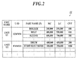
- identification information (called, U-ID) of a unit and the replacement time count value MC, the life duration time count value LC and the use count value CNT of each part P which is installed in the unit are stored in the storage section 11 for each of the units U1 to Un which are installed in the printer section 50.
- the replacement time count value MC is a print count value showing a replacement time of a part P, and is set by a maker for each part P so as to have a certain time of grace period till the life duration count value.
- the life duration count value LC is a print count value showing a life duration time of a part P, and is a value set by a maker based on a number of sheets printed which is a limit where the maker cannot assure the quality of the printed matter when the part is used thereafter, for example.
- the replacement time count value MC a conventional maintenance count which is set as the part replacement time at the time of routine maintenance by a service man can be used.
- the maintenance count is set by a maker so that the parts P in which the difference between the life duration count value LC is within a certain range can be replaced at once at the time of routine maintenance.
- the use count value CNT is a print count value in which the part P has been used.
- the operation section 20 comprises the key input section 21, the display section 22 and the like.
- the key input section 21 comprises various types of operation keys (see FIG. 7 ) such as ten keys 211, a start key 212, a YES key 213, a NO key 214, a power supply key for switching ON/OFF of the power supply and the like, and the operation signal by the key operation is outputted to the control section 10.
- operation keys see FIG. 7
- ten keys 211 such as ten keys 211, a start key 212, a YES key 213, a NO key 214, a power supply key for switching ON/OFF of the power supply and the like, and the operation signal by the key operation is outputted to the control section 10.
- the display section 22 is constituted with a LCD (Liquid Crystal Display) and the like, and displays various types of operation screens, a condition display of an image, an operation condition of each function and the like according to an instruction of a display signal inputted from the control section 10.
- LCD Liquid Crystal Display
- the scanner section 30 comprises a platen glass, a CCD (Charge Coupled Device) and a light source.
- the scanner section 30 reads an image of a document which is set at a predetermined position as signals of R, G and B by imaging the reflection light of a light which is illumination scanned to the document from the light source by the CCD to carry out the photoelectric conversion, and converts the read analog image signal to image data of R, G and B to output to the control section 10.
- the communication section 40 is an interface which can be connected to a transmission medium connected to the communication network such as the LAN (Local Area Network), the WAN (Wide Area Network) and the like.
- the communication section 40 is constituted with a communication control card such as a LAN card or the like, for example, and carries out sending and receiving of various types of data between an external device of the host device 200 or the like which is connected to the communication network via the communication circuit such as the LAN cable or the like.
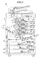
- the printer section 50 forms an toner image on a paper by the electrophotographic process based on the image data inputted from the control section 10.
- the printer section 50 comprises laser sections 40Y, 40M, 40C and 40K which write the latent image on the photoconductor drums by exposing laser to the photoconductor drums 51Y, 51M, 51C and 51K based on the image data inputted by the control section 10, image forming sections 50Y, 50M, 50C and 50K which form toner images of each color of Y, M, C and K, an intermediate transfer belt 56 as an intermediate transferring body to which the toner images formed at the image forming sections 50Y, 50M, 50C and 50K are temporarily transferred, a resist roller 58 which conveys a paper to the secondary transfer roller 59 by synchronizing with the toner image formed on the intermediate transfer belt 56, a secondary transfer roller 59 which carries out the secondary transfer of the toner images which are formed on the intermediate transfer belt 56 to the paper, a fixing unit 63 to fix the toner images on the paper and a paper e
- the image forming section 50Y comprises the photoconductor drum 51Y, the developer 52Y, the charger 53Y, the cleaner 54Y and the primary transfer roller 55Y.
- the image forming sections 50M, 50C and 50K are also structured in a similar manner.
- the print operation in the printer section 50 will be described.
- the photoconductor drum 51Y is rotated and the surface of the photoconductor drum is charged by the charger 53Y, and a latent image of the Y data is formed at the charged portion by the exposure of the laser light source of the laser section 40Y.
- the latent portion is developed by the developer 52Y to form the toner image of yellow.
- the toner image is primary transferred to the intermediate transfer belt 56 by the pressing of the primary transfer roller 55Y.
- the toner image becomes the image of yellow corresponding to the image data of the output subject. Toner which was not primary transferred is removed by the cleaner 54Y.
- a toner image of magenta, the toner image of cyan and a toner image of black are respectively formed and transferred in a similar manner.
- the intermediate transfer belt 56 is rotated by the rotation of the roller 57, the primary transfer rollers 55Y, 55M, 55C and 55K, the secondary transfer roller 59, and the toner image of YMCK are orderly layered on the intermediate transfer belt 56 to be transferred. Further, paper is conveyed one by one from any of the paper feeding trays 66A to 66C by any of the paper feeding rollers 68A to 68C rotating, and the paper is conveyed to the secondary transfer roller 59 by the rotation of the resist roller 58.
- the toner image of YMCK on the intermediate transfer belt 56 is secondary transferred to the paper.
- the paper on which the toner image of YMCK is transferred passes through the fixing unit 63.
- the toner image of YMCK is fixed on the paper and the colored toner image is formed.
- the paper on which the image is formed is ejected by the paper ejection roller 67.
- the paper in which an image is formed on one side is sent to the both-side conveyance unit 65 by the conveyance switching board 64 and the surface of the paper is reversed by the both-side conveyance unit 65. Then, the paper is conveyed to the secondary transfer roller 59 by the resist roller 58 so that the image forming is to be carried out again to the surface (back side) on which an image is not formed to carry out the image forming.
- the paper on which images are formed on both sides and in which the toner is fixed is conveyed to the paper ejection tray 69 and the like by the paper ejection roller 67.
- residual toner on the intermediate transfer belt 56 is removed by the belt cleaning 62. Further, by applying a current of plus polarity and a current of minus polarity from the power supply 67 to the secondary transfer roller 59 by switching between the currents for a predetermined period of time, the residual toner at the secondary transfer roller 59 is retransferred to the intermediate transfer belt 56 to carry out the cleaning of the secondary transfer roller 59.
- Each part of the printer section 50 described above is driven via various types of motors (omitted from the drawing) by a command of the control section 10.
- the printer section 50 is constituted by using a plurality of replaceable units U1 to Un as described above.
- one or a plurality of parts P are collected and grouped as individual assemblies.
- parts P including replaceable parts P
- the printer section 50 is constituted by using a plurality of replaceable units U1 to Un as described above.
- one or a plurality of parts P are collected and grouped as individual assemblies.
- the IC tag 70 as a recording medium is attached to each of the units U1 to Un which are installed in the printer section 50.
- FIG. 4 an example of data storage in the IC tag 70 is shown.
- the U-ID for identifying the unit to which the IC tag 70 is attached and the replacement time count value MC, the life duration time count value LC and the use count value CNT for each of the parts P (for example, a roller, a belt, a sleeve ...) which are installed in the unit are stored in the IC tag 70.
- the replacement time count value MC, the life duration time count value LC and the use count value CNT of each of the parts P are stored in the IC tag 70 to manage the information.
- the U-ID may be stored in the IC tag 70 and the replacement time count value MC, the life duration time count value LC and the use count value CNT of each of the parts P may be stored in the external device such as a server by being corresponded with the U-ID.
- the reader/writer section 60 comprises an IC tag communication control section 61, an antenna drive circuits 621 to 62n and the antennas 631 to 63n.
- the antenna drive circuits 621 to 62n and the antennas 631 to 63n are respectively corresponded to the units U1 to Un, and the antenna 631 to 63n are respectively provided at positions opposite to the units U1 to Un.
- the IC tag communication control section. 61 controls the antenna drive circuits 621 to 62n based on the instruction from the control section 10 and electromagnetically induces the IC tag 70 of the units U1 to Un via the antennas 631 to 63n to carryout sending and receiving of data by noncontact communication. Then, reading and writing of the data to the IC tag 70 of the units U1 to Un are carried out.
- the power supply section 80 is connected to the commercial AC power supply (omitted from the drawing), and converts the AC source power inputted from the commercial AC power supply to the DC source power to supply to each of the parts which needs electric voltage.
- the power supply section 80 supplies power according to the control command from the control section 10.
- the unit replacement check process (see FIG. 5 ) is executed at the time when the power supply is turned ON to check whether unit replacement was carried out while the power supply of the main body is OFF.
- FIG. 5 a flow of the unit replacement check process to be executed by the control section 10 at the time when the power supply is turned ON is shown.
- the U-ID is read from each of the IC tags 70 attached to the units U1 to Un installed in the printer section 50 via the reader/writer section 60 (step S1).
- step S2 whether a unit in which the U-ID is changed exists or not is determined by comparing the U-ID read from the IC tags 70 of the Units U1 to Un to the U-ID of the units U1 to Un stored in the storage section 11 (step S2).
- step S4 When it is determined that a unit in which the U-ID is changed does not exist (step S2; NO), the image forming apparatus is switched to a standby state (step S4) and the process is finished.
- step S2 when it is determined that there is a unit in which the U-ID is changed (step S2; YES), the U-ID in the IC tag 70 of the unit in which the U-ID is changed and the replacement time count value MC, the life duration time count value LC and the use count value CNT of each of the parts P are read via the reader/writer section 60 to update the storage section 11 (step S3). Then, the image forming apparatus is switched to a standby state (step S4) and the process is finished.
- the image forming apparatus 100 After the above described unit replacement check process, the image forming apparatus 100 will be in a standby state. However, when a job execution is instructed via the operation section 20 or the communication section 40, the print process (see FIG. 6 ) is executed.
- FIG. 6 a flow of the print process to be executed by the control section 10 is shown.
- step S11 printing of the number of sheets to be printed (set to number of sheets printed m) which is instructed via the operation section 20 or the communication section 40 is executed (step S11).
- step S12 printing of the number of sheets to be printed (set to number of sheets printed m) which is instructed via the operation section 20 or the communication section 40 is executed (step S11).
- step S12 the counter i is set to 1 (step S12), and 1-count up (step S14) and the 1-incliment (step S15) of the use count value CNT of each of the parts P in the storage section 11 are repeated until i>number of sheets printed m is achieved.
- step S13 When it is determined that i>number of print sheets m (step S13; YES), the use count value CNT of each part P in the IC tag 70 of the units Un to Un is updated according to the use count value CNT of each part P in the storage section 11 via the reader/writer section 60 (step S16).
- the image forming process is switched to a standby state (step S21) and the process is finished.
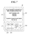
- FIG. 7 an example of the notification screen 221 to be displayed in the display section 22 in step S18 of FIG. 6 is shown.
- name of the part to be replaced and a message for urging replacement of a unit in which the part P to be replaced is installed are displayed in the notification screen 221. Further, a message for asking whether to transfer to the maintenance mode or not is displayed.
- the YES key 213 of the key input section 21 is pushed, the process is transferred to the maintenance mode.
- the NO key 214 of the key input section 21 is pushed, the image forming apparatus is switched to a standby state.
- step S19; YES When the YES key 213 of the key input section 21 is pressed to instruct the process to transfer to the maintenance mode in a condition where the notification screen 221 is displayed in the display section 22 (step S19; YES), the maintenance mode process is executed (step S20) and the process is finished.
- step S19; NO When the NO key 214 of the key input section 21 is pushed to instruct the process not to transfer to the maintenance mode in a condition where the notification screen 221 is displayed in the display section 22 (step S19; NO), the image forming apparatus is switched to a standby state (step S21) and the process is finished.
- a notification screen 221 which urges to replace the one part P and the other parts P in which the use count value CNT is within the range between the replacement time count value MC and the life duration time count value LC (called, period Z) is displayed in the display section 22.
- the notification screen 221 is also displayed in a case where breakdown occurs in any of the parts P and the units. Then, when the YES key 213 of the key input section 21 is pushed in a condition where the notification screen 221 is displayed in the display section 22 to transfer to the maintenance mode, the maintenance mode process is executed.
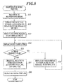
- FIG. 8 a flow of the maintenance mode process to be executed in the control section 10 is shown.
- the image forming apparatus is switched to the maintenance mode and power supply to the scanner section 30, the printer section 50 and the like is stopped (step S31).
- the use count value CNT of each part P in each of the IC tags 70 is updated according to the updated use count value CNT in the storage section 11 via the reader/writer section 60 (step S32).
- a message such as "Please start replacement” or the like is displayed in the display section 22 (step S33).
- a message such as "Please push YES key when replacement is completed” or the like is also displayed in the display section 22 and an input of replacement completion is awaited.
- a user pulls out a unit in which the part P which is urged to be replaced in the display section 22 is installed from the printer section 50 to carry out a unit replacement.
- the unit to be newly installed is a backup unit which followed the after-mentioned part replacement procedure by a service man (see FIG. 9 ) or a unit which is constituted with brand new parts P.
- step S34 When the YES key 213 of the key input section 21 is pushed and when an input indicating replacement completion is carried out (step S34), the U-ID is read from the IC tag 70 of the unit which is the replacement target and whether the U-ID of the unit which is the replacement target is changed or not is determined by comparing to the U-ID of the unit which is stored in the storage section 11 (step S35). When it is determined that the U-ID of the unit which is the replacement target is not changed (step S35; NO), a message urging replacement such as "Unit is not replaced. Please replace with new unit.” or the like is displayed in the display section 22 (step S36) and the process returns to waiting for the input of replacement completion of step S34.
- step S35 When it is determined that the U-ID of the unit which is the replacement target is changed (step S35; YES), the U-ID in the storage section 11 is updated to the U-ID of the unit which is replaced, and also, the life duration time count value LC, the replacement time count value MC, the use count value CNT of each part P stored in the IC tag 70 of the pertinent unit are read to update the life duration time count value LC, the replacement time count value MC and the use count value CNT in the storage section 11 according to the read values (step S37). Then, power supply to the scanner section 30, the printer section 50 and the like is resumed, and also, a message such as "copy, OK" or the like is displayed in the display section 22 (step S38) and the process is finished.
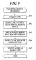
- the unit which is pulled out from the case of the printer section 50 by a user in the above maintenance mode process is to be replaced by a service man in the procedure shown in FIG. 9 .
- a service man in the procedure shown in FIG. 9 .
- the part replacement procedure carried out by a service man will be described.
- step S41 a unit is collected (step S41).
- step S42 the life duration time count value LC, the replacement time count value MC and the use count value CNT of the IC tag 70 which is attached to the unit is read by a special IC tag reader/writer (step S42).
- the read life duration count value IC, replacement time count value MC, use count value CNT are referred to replace the part P which has reached the period Z with a new part P (step S43).
- the use count value CNT of the replaced part P in the IC tag 70 is reset (step S44).
- the unit in which the part P is replaces is sent to a user as a backup unit (step S45).
- the use count value CNT of the part P which is replaced with a new part P is reset and the use count value CNT remains as it is for the parts P which are not replaced. Then, when the unit is sent to a user as a backup unit and when a unit replacement is carried out during the maintenance mode process shown in FIG. 8 , the use count value CNT is started from 0 for the new part P. However, counting of number of sheets printed is carried out from the use count value CNT which shows the number of times the part is used until now for the parts P other than the new part P which have been used. In such way, each of the parts P can be continuously used until reaching the period Z.
- the control section 10 updates the use count value CNT of the IC tag 70 of each of the units U1 to Un according to the updated use count value CNT in the storage section 11.
- the unit replacement check process shown in FIG. 5 is executed. Therefore, variance does not occur in the use count value CNT of each of the parts P even when the unit replacement is carried out when the power supply is OFF.
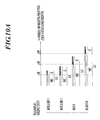
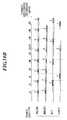
- FIGS. 10A to 10C are diagrams for explaining part replacement time in the image forming apparatus 100.
- the FIG. 10A shows the replacement time count value MC, the life duration time count value LC and the period Z which is between the replacement time count value MC and the life duration time count value LC of a roller 1, a roller 2, a belt and a sleeve installed in the fixing unit 63.
- FIG. 10B shows a unit replacement which takes place when 2 million prints are carried out without each part P breaking down in one fixing unit 63 in which each of the parts P having the replacement time count value MC, the life duration time count value LC and the period Z shown in FIG. 10A (shown in dashed line in FIG. 10B ).
- FIG. 10A shows the replacement time count value MC, the life duration time count value LC and the period Z which is between the replacement time count value MC and the life duration time count value LC of a roller 1, a roller 2, a belt and a sleeve installed in the fixing unit 63
- 10C shows a unit replacement which takes place when the roller 1 breaks down just when the number of sheets printed exceeded 400,000, when the sleeve breaks down just when the number of sheets printed exceeded 700,000 and when the belt breaks down just when the number of sheets printed exceeded 1, 100, 000 for one fixing unit 63 in which each part P having the replacement time count value MC, the life duration time count value LC and the period Z shown in FIG. 10A (shown in dashed line in FIG. 10C ).
- the one fixing unit 63 when unit replacement is carried out before the number of sheets printed of the one fixing unit 63 reaches 2 million, the one fixing unit 63 will be temporarily removed from the image forming apparatus 100. However, when the unit is reinstalled, as shown in the part replacement procedure of a service man in FIG. 9 , the use count value CNT of the replaced part P will be reset to 0 and the use count value CNT of the part P which is not replaced will be carried over. Therefore, the relation between the use count value CNT of each part P in the same fixing unit 63 and the unit replacement can be shown as in FIGS. 10B and 10C .
- the image forming apparatus 100 of the embodiment when a part P in the units U1 to Un reached the life duration time count value LC, it is determined whether any other parts P which have reached the period Z exist among other parts P or not by the print process shown in FIG. 6 .
- a notification screen 221 indicating to replace the part P which has reached the period Z at the same time along with the part P which have reached the life duration time count value LC is displayed.
- a user replaces the unit in which the part P which is notified by the notification screen 221 is installed and a service man carried out the part replacement for the pars which are in the period Z in the replaced unit.
- the control section 10 detects for part P in which the replacement time count value MC ⁇ the use count value CNT ⁇ the life duration time count value LC among other parts P and displays the notification screen to urge the replacement of all of the parts P in which the replacement time count value MC ⁇ the use count value CNT ⁇ the life duration time count value LC in the display section 22.
- each unit U1 to Un the IC tag 70 in which the replacement time count value MC, the life duration time count value LC and the use count value CNT of each part P installed in the unit is stored so as to correspond to the each part P is attached.
- the control section 10 reads the replacement time count value MC, the life duration time count value LC and the use count value CNT of each part P installed in the unit which are storage in the IC tag 70 of the unit by the reader/writer section 60 and stores the read values in the storage section 11. Therefore, even when the part P having different replacement time count value MC and the life duration time count value LC is installed as the part P of same function by the part replacement, the replacement time can be managed according to the installed part P.
- the above description of the embodiment is a preferable example of the image forming apparatus 100 and the present invention is not limited to this.
Landscapes
- Physics & Mathematics (AREA)
- General Physics & Mathematics (AREA)
- Engineering & Computer Science (AREA)
- Microelectronics & Electronic Packaging (AREA)
- Human Computer Interaction (AREA)
- Control Or Security For Electrophotography (AREA)
Applications Claiming Priority (1)
| Application Number | Priority Date | Filing Date | Title |
|---|---|---|---|
| JP2008160115A JP2010002554A (ja) | 2008-06-19 | 2008-06-19 | 画像形成装置 |
Publications (2)
| Publication Number | Publication Date |
|---|---|
| EP2136255A2 true EP2136255A2 (de) | 2009-12-23 |
| EP2136255A3 EP2136255A3 (de) | 2012-08-29 |
Family
ID=41078280
Family Applications (1)
| Application Number | Title | Priority Date | Filing Date |
|---|---|---|---|
| EP09162146A Withdrawn EP2136255A3 (de) | 2008-06-19 | 2009-06-08 | Bilderzeugungsvorrichtung |
Country Status (4)
| Country | Link |
|---|---|
| US (1) | US20090317099A1 (de) |
| EP (1) | EP2136255A3 (de) |
| JP (1) | JP2010002554A (de) |
| CN (1) | CN101609279A (de) |
Cited By (2)
| Publication number | Priority date | Publication date | Assignee | Title |
|---|---|---|---|---|
| JP2013011693A (ja) * | 2011-06-28 | 2013-01-17 | Brother Ind Ltd | 画像形成装置 |
| EP2290457A3 (de) * | 2009-08-25 | 2013-12-04 | Konica Minolta Business Technologies | Bilderzeugungsvorrichtung |
Families Citing this family (6)
| Publication number | Priority date | Publication date | Assignee | Title |
|---|---|---|---|---|
| JP5413205B2 (ja) * | 2010-01-13 | 2014-02-12 | コニカミノルタ株式会社 | 画像形成装置 |
| JP2012123251A (ja) * | 2010-12-09 | 2012-06-28 | Canon Inc | 画像形成装置 |
| JP5885434B2 (ja) * | 2011-08-31 | 2016-03-15 | キヤノン株式会社 | 画像形成装置、その方法、及びプログラム |
| JP2016006488A (ja) * | 2014-05-29 | 2016-01-14 | キヤノン株式会社 | 定着器および画像形成装置 |
| JP6459562B2 (ja) * | 2015-01-28 | 2019-01-30 | コニカミノルタ株式会社 | 画像形成装置の管理プログラム、画像形成装置の管理プログラムを記録した記録媒体、および画像形成装置の管理方法 |
| JP7367320B2 (ja) * | 2019-03-28 | 2023-10-24 | ブラザー工業株式会社 | 現像カートリッジ、ドラムカートリッジ、ベルトユニットおよび画像形成装置 |
Citations (2)
| Publication number | Priority date | Publication date | Assignee | Title |
|---|---|---|---|---|
| JP2005107440A (ja) | 2003-10-02 | 2005-04-21 | Ricoh Co Ltd | プロセスカートリッジ、装置ユニット、画像形成装置、及び、リサイクル方法 |
| JP2008160115A (ja) | 2004-11-12 | 2008-07-10 | Tokai Kogaku Kk | 赤外線受発光部 |
Family Cites Families (16)
| Publication number | Priority date | Publication date | Assignee | Title |
|---|---|---|---|---|
| JPS6295552A (ja) * | 1985-10-22 | 1987-05-02 | Toshiba Corp | 画像形成装置 |
| JP3106504B2 (ja) * | 1990-12-17 | 2000-11-06 | ミノルタ株式会社 | 画像形成装置 |
| US5491540A (en) * | 1994-12-22 | 1996-02-13 | Hewlett-Packard Company | Replacement part with integral memory for usage and calibration data |
| JP3311248B2 (ja) * | 1996-07-26 | 2002-08-05 | キヤノン株式会社 | プロセスカートリッジおよび画像形成装置 |
| JP3417240B2 (ja) * | 1997-01-23 | 2003-06-16 | 富士ゼロックス株式会社 | 電子写真装置 |
| US5950038A (en) * | 1997-02-27 | 1999-09-07 | Kyocera Corporation | Image formation apparatus |
| JP2000098826A (ja) * | 1998-09-28 | 2000-04-07 | Fuji Xerox Co Ltd | 画像形成装置 |
| JP2001134153A (ja) * | 1999-11-05 | 2001-05-18 | Fujitsu Ltd | 電子写真装置 |
| US6351618B1 (en) * | 2000-12-20 | 2002-02-26 | Xerox Corporation | Method of using a security system for replaceable cartridges for printing machines |
| JP3858640B2 (ja) * | 2001-08-09 | 2006-12-20 | 村田機械株式会社 | 画像形成装置 |
| US6647213B2 (en) * | 2001-11-30 | 2003-11-11 | Kabushiki Kaisha Toshiba | Image forming apparatus having a mode in which a process unit may be replaced |
| JP3951996B2 (ja) * | 2003-09-18 | 2007-08-01 | コニカミノルタビジネステクノロジーズ株式会社 | 画像形成装置 |
| KR100553897B1 (ko) * | 2003-10-31 | 2006-02-24 | 삼성전자주식회사 | 메모리를 이용한 화상형성장치의 소모품 관리 장치 |
| KR100607961B1 (ko) * | 2004-01-24 | 2006-08-03 | 삼성전자주식회사 | 화상 형성 장치, 화상 형성 장치에 포함되는 소모품 및소모품의 상태 관리 방법 |
| JP2006085038A (ja) * | 2004-09-17 | 2006-03-30 | Ricoh Co Ltd | 画像形成ユニット及びこれを用いた画像形成装置、並びに画像形成ユニットの再生方法 |
| JP4735850B2 (ja) * | 2006-11-28 | 2011-07-27 | 富士ゼロックス株式会社 | 消耗品管理装置、画像形成装置及びプログラム |
-
2008
- 2008-06-19 JP JP2008160115A patent/JP2010002554A/ja active Pending
-
2009
- 2009-06-08 EP EP09162146A patent/EP2136255A3/de not_active Withdrawn
- 2009-06-09 US US12/480,852 patent/US20090317099A1/en not_active Abandoned
- 2009-06-17 CN CNA2009101491512A patent/CN101609279A/zh active Pending
Patent Citations (2)
| Publication number | Priority date | Publication date | Assignee | Title |
|---|---|---|---|---|
| JP2005107440A (ja) | 2003-10-02 | 2005-04-21 | Ricoh Co Ltd | プロセスカートリッジ、装置ユニット、画像形成装置、及び、リサイクル方法 |
| JP2008160115A (ja) | 2004-11-12 | 2008-07-10 | Tokai Kogaku Kk | 赤外線受発光部 |
Cited By (2)
| Publication number | Priority date | Publication date | Assignee | Title |
|---|---|---|---|---|
| EP2290457A3 (de) * | 2009-08-25 | 2013-12-04 | Konica Minolta Business Technologies | Bilderzeugungsvorrichtung |
| JP2013011693A (ja) * | 2011-06-28 | 2013-01-17 | Brother Ind Ltd | 画像形成装置 |
Also Published As
| Publication number | Publication date |
|---|---|
| US20090317099A1 (en) | 2009-12-24 |
| CN101609279A (zh) | 2009-12-23 |
| EP2136255A3 (de) | 2012-08-29 |
| JP2010002554A (ja) | 2010-01-07 |
Similar Documents
| Publication | Publication Date | Title |
|---|---|---|
| EP2136255A2 (de) | Bilderzeugungsvorrichtung | |
| EP1055979B1 (de) | Bilderzeugungsgerät und in diesem Gerät montierbare Arbeitseinheit | |
| CN102621846B (zh) | 打印装置及其控制方法以及盒 | |
| US9588460B2 (en) | Image forming apparatus | |
| US5850583A (en) | Techniques for generating status messages in image forming apparatus | |
| US8971733B2 (en) | Image forming unit and image forming apparatus | |
| JP2002287920A (ja) | 画像形成制御ソフトウェアの配信に係る情報処理装置及び情報処理方法及びプログラム及び記憶媒体 | |
| JP2011112897A (ja) | 画像処理装置、画像形成装置、及びプログラム | |
| JP6208516B2 (ja) | 画像形成装置、画像形成装置の制御方法、プログラムおよび記録媒体 | |
| JP5445776B2 (ja) | 画像形成装置 | |
| US20070177439A1 (en) | Displaying supply information of an image forming apparatus | |
| US8041235B2 (en) | Image forming apparatus, adjusting method thereof and replacement component thereof | |
| JP2011118144A (ja) | 画像形成装置 | |
| US20100150581A1 (en) | Image forming apparatus | |
| CN101063867B (zh) | 图像形成装置 | |
| JP2004341283A (ja) | 画像形成装置 | |
| CN102213923B (zh) | 图像形成设备和显示方法 | |
| US11301871B2 (en) | CRUM apparatus to extract power from clock signal having first and second periods | |
| JP2011128189A (ja) | 画像形成装置及び画像形成システム | |
| US12267474B2 (en) | Information processing apparatus and method for notifying a user at an appropriate timing that a calibration is required | |
| JP5810775B2 (ja) | 画像形成装置 | |
| JP5262629B2 (ja) | 画像形成装置及びプログラム | |
| JP5358375B2 (ja) | 画像形成装置 | |
| JP2017211679A (ja) | 画像形成装置、画像形成装置の制御方法、プログラムおよび記録媒体 | |
| JP2005257816A (ja) | 印刷装置 |
Legal Events
| Date | Code | Title | Description |
|---|---|---|---|
| PUAI | Public reference made under article 153(3) epc to a published international application that has entered the european phase |
Free format text: ORIGINAL CODE: 0009012 |
|
| AK | Designated contracting states |
Kind code of ref document: A2 Designated state(s): AT BE BG CH CY CZ DE DK EE ES FI FR GB GR HR HU IE IS IT LI LT LU LV MC MK MT NL NO PL PT RO SE SI SK TR |
|
| PUAL | Search report despatched |
Free format text: ORIGINAL CODE: 0009013 |
|
| AK | Designated contracting states |
Kind code of ref document: A3 Designated state(s): AT BE BG CH CY CZ DE DK EE ES FI FR GB GR HR HU IE IS IT LI LT LU LV MC MK MT NL NO PL PT RO SE SI SK TR |
|
| AX | Request for extension of the european patent |
Extension state: AL BA RS |
|
| RIC1 | Information provided on ipc code assigned before grant |
Ipc: G03G 15/00 20060101AFI20120725BHEP |
|
| STAA | Information on the status of an ep patent application or granted ep patent |
Free format text: STATUS: THE APPLICATION IS DEEMED TO BE WITHDRAWN |
|
| 18D | Application deemed to be withdrawn |
Effective date: 20130301 |