EP2131003A2 - Agencement d'arbres rotatifs pour une porte, notamment pour une porte roulante et une telle porte - Google Patents
Agencement d'arbres rotatifs pour une porte, notamment pour une porte roulante et une telle porte Download PDFInfo
- Publication number
- EP2131003A2 EP2131003A2 EP20090161913 EP09161913A EP2131003A2 EP 2131003 A2 EP2131003 A2 EP 2131003A2 EP 20090161913 EP20090161913 EP 20090161913 EP 09161913 A EP09161913 A EP 09161913A EP 2131003 A2 EP2131003 A2 EP 2131003A2
- Authority
- EP
- European Patent Office
- Prior art keywords
- rotary shaft
- door
- weight
- door leaf
- arrangement
- Prior art date
- Legal status (The legal status is an assumption and is not a legal conclusion. Google has not performed a legal analysis and makes no representation as to the accuracy of the status listed.)
- Granted
Links
- 238000004804 winding Methods 0.000 claims description 38
- 230000007246 mechanism Effects 0.000 claims description 10
- 230000005540 biological transmission Effects 0.000 claims description 8
- 230000008878 coupling Effects 0.000 claims description 8
- 238000010168 coupling process Methods 0.000 claims description 8
- 238000005859 coupling reaction Methods 0.000 claims description 8
- 238000002347 injection Methods 0.000 claims 1
- 239000007924 injection Substances 0.000 claims 1
- 238000009434 installation Methods 0.000 description 5
- 150000001875 compounds Chemical class 0.000 description 3
- 230000001419 dependent effect Effects 0.000 description 3
- 238000000465 moulding Methods 0.000 description 3
- XAGFODPZIPBFFR-UHFFFAOYSA-N aluminium Chemical compound [Al] XAGFODPZIPBFFR-UHFFFAOYSA-N 0.000 description 2
- 229910052782 aluminium Inorganic materials 0.000 description 2
- 230000008901 benefit Effects 0.000 description 2
- 230000003993 interaction Effects 0.000 description 2
- 229910000831 Steel Inorganic materials 0.000 description 1
- 230000015572 biosynthetic process Effects 0.000 description 1
- 239000000969 carrier Substances 0.000 description 1
- 230000008859 change Effects 0.000 description 1
- 239000000470 constituent Substances 0.000 description 1
- 238000010276 construction Methods 0.000 description 1
- 238000005553 drilling Methods 0.000 description 1
- 238000000034 method Methods 0.000 description 1
- 239000012778 molding material Substances 0.000 description 1
- 230000008569 process Effects 0.000 description 1
- 239000010959 steel Substances 0.000 description 1
Images


Classifications
-
- E—FIXED CONSTRUCTIONS
- E06—DOORS, WINDOWS, SHUTTERS, OR ROLLER BLINDS IN GENERAL; LADDERS
- E06B—FIXED OR MOVABLE CLOSURES FOR OPENINGS IN BUILDINGS, VEHICLES, FENCES OR LIKE ENCLOSURES IN GENERAL, e.g. DOORS, WINDOWS, BLINDS, GATES
- E06B9/00—Screening or protective devices for wall or similar openings, with or without operating or securing mechanisms; Closures of similar construction
- E06B9/02—Shutters, movable grilles, or other safety closing devices, e.g. against burglary
- E06B9/08—Roll-type closures
- E06B9/11—Roller shutters
- E06B9/17—Parts or details of roller shutters, e.g. suspension devices, shutter boxes, wicket doors, ventilation openings
- E06B9/174—Bearings specially adapted therefor
-
- E—FIXED CONSTRUCTIONS
- E05—LOCKS; KEYS; WINDOW OR DOOR FITTINGS; SAFES
- E05D—HINGES OR SUSPENSION DEVICES FOR DOORS, WINDOWS OR WINGS
- E05D13/00—Accessories for sliding or lifting wings, e.g. pulleys, safety catches
- E05D13/10—Counterbalance devices
- E05D13/12—Counterbalance devices with springs
- E05D13/1207—Counterbalance devices with springs with tension springs
- E05D13/1223—Spring safety devices
-
- E—FIXED CONSTRUCTIONS
- E05—LOCKS; KEYS; WINDOW OR DOOR FITTINGS; SAFES
- E05F—DEVICES FOR MOVING WINGS INTO OPEN OR CLOSED POSITION; CHECKS FOR WINGS; WING FITTINGS NOT OTHERWISE PROVIDED FOR, CONCERNED WITH THE FUNCTIONING OF THE WING
- E05F15/00—Power-operated mechanisms for wings
- E05F15/60—Power-operated mechanisms for wings using electrical actuators
- E05F15/603—Power-operated mechanisms for wings using electrical actuators using rotary electromotors
- E05F15/665—Power-operated mechanisms for wings using electrical actuators using rotary electromotors for vertically-sliding wings
- E05F15/668—Power-operated mechanisms for wings using electrical actuators using rotary electromotors for vertically-sliding wings for overhead wings
- E05F15/681—Power-operated mechanisms for wings using electrical actuators using rotary electromotors for vertically-sliding wings for overhead wings operated by flexible elongated pulling elements, e.g. belts
- E05F15/686—Power-operated mechanisms for wings using electrical actuators using rotary electromotors for vertically-sliding wings for overhead wings operated by flexible elongated pulling elements, e.g. belts by cables or ropes
-
- E—FIXED CONSTRUCTIONS
- E06—DOORS, WINDOWS, SHUTTERS, OR ROLLER BLINDS IN GENERAL; LADDERS
- E06B—FIXED OR MOVABLE CLOSURES FOR OPENINGS IN BUILDINGS, VEHICLES, FENCES OR LIKE ENCLOSURES IN GENERAL, e.g. DOORS, WINDOWS, BLINDS, GATES
- E06B9/00—Screening or protective devices for wall or similar openings, with or without operating or securing mechanisms; Closures of similar construction
- E06B9/02—Shutters, movable grilles, or other safety closing devices, e.g. against burglary
- E06B9/08—Roll-type closures
- E06B9/11—Roller shutters
- E06B9/17—Parts or details of roller shutters, e.g. suspension devices, shutter boxes, wicket doors, ventilation openings
- E06B9/171—Rollers therefor; Fastening roller shutters to rollers
-
- E—FIXED CONSTRUCTIONS
- E05—LOCKS; KEYS; WINDOW OR DOOR FITTINGS; SAFES
- E05Y—INDEXING SCHEME RELATING TO HINGES OR OTHER SUSPENSION DEVICES FOR DOORS, WINDOWS OR WINGS AND DEVICES FOR MOVING WINGS INTO OPEN OR CLOSED POSITION, CHECKS FOR WINGS AND WING FITTINGS NOT OTHERWISE PROVIDED FOR, CONCERNED WITH THE FUNCTIONING OF THE WING
- E05Y2900/00—Application of doors, windows, wings or fittings thereof
- E05Y2900/10—Application of doors, windows, wings or fittings thereof for buildings or parts thereof
- E05Y2900/106—Application of doors, windows, wings or fittings thereof for buildings or parts thereof for garages
Definitions
- the present invention relates to a rotary shaft arrangement for a gate, in particular for a roller shutter, with a rotating shaft about a rotation axis. Furthermore, the invention relates to a provided with such a rotary shaft assembly gate, in particular a roller door.
- the door leaf is designed, in particular, as a door curtain and comprises, for example, a multiplicity of panels or roller shutter rods which are joined together in an articulated manner and which can be rolled up around a rotary shaft designed as a winding shaft.
- a recessed in the winding shaft tubular motor or a flanged on the winding shaft worm gear motor is provided.
- spring compensations for the weight balance of the door leaf is carried out to reduce the drive power often by a arranged in the rotary or winding shaft torsion spring or by rotatably mounted on the rotary or winding coil spring packages.
- the object of the invention is to provide a rotary shaft arrangement and a gate, so that the rotary shaft arrangement or the door can be adapted in a simple manner to the mounting situation prevailing at the installation location.
- the weight compensation device can be fastened in different positions relative to the axis of rotation positionable and rotationally fixed to the rotary shaft.
- the equalizing characteristic is achieved not by exchanging the one counterbalancing device and replacing by another counterbalancing device, but by using one and the same counterbalancing device, which can be mounted in different positions relative to the rotary shaft. In this way, in order to set the optimum for the installation situation compensation characteristic of the weight balancing device, this brought into one of several available positions and then rotatably secured to the rotary shaft.
- a simple adjustment or adjustment, in particular a fine adjustment, of the compensation characteristic is possible.
- the positioning of the weight compensation device in the various positions is preferably achieved in that the weight compensation device can be positioned in different predetermined angular positions relative to the axis of rotation.
- a gear structure with a predetermined pitch can be provided for this purpose, which will be explained in more detail below.
- an adjusting device is provided, by means of which the weight compensation device is coupled to the rotary shaft, wherein the adjusting device provides the various positions relative to the axis of rotation. In each of these positions, the weight balancer can be attached to the rotary shaft. Depending on which of the available positions is selected, so can still be done some fine adjustment of the compensation characteristic.
- this adjustment means comprises a first adjustment unit and a second adjustment unit, the first adjustment unit being associated with the rotary shaft and the second adjustment unit being associated with the weight compensation device.
- the components forming the adjustment device can be assigned to different constituents of the rotary shaft arrangement and / or all can be integrated into the weight compensation device.
- the first adjustment unit and the second adjustment unit can be connected to one another by means of a non-positive connection and / or can be engaged and disengaged from one another as a positive connection.
- the first or second adjustment unit has projections and the other adjustment unit recesses in a manner such that the projections and recesses are positively connected with each other.
- the projections and / or recesses are formed by a gear structure having a predetermined pitch and / or a predetermined pitch angle.
- the pitch angle is between about 5 ° and about 20 °, in particular between about 8 ° and about 12 °.
- the rotary shaft is designed as a toothed shaft, with the projections forming the teeth and the recesses or grooves present between the projections extending parallel to the longitudinal direction of the rotary shaft or parallel to the axis of rotation.
- the weight compensation device has a winding device, in particular a conical winding drum, with a predetermined basic compensation characteristic.
- the weight compensation device can provide a basic compensation characteristic and at the same time an additional compensation characteristic due to its design and / or its interaction with the rotary shaft.
- the weight compensation device may comprise a spring unit.
- the spring unit comprises at least one tension spring.
- a plurality of mutually arranged tension springs can be provided.
- the tension springs may be substantially concentric with each other and / or be wound in opposite directions.
- the weight compensation device may comprise a coupling element, via which the spring unit is coupled to the winding device, wherein preferably the coupling element comprises at least one cable, in particular two cables.
- the coupling element comprises at least one cable, in particular two cables.
- At least one driver for transmitting the rotational movement of the rotary shaft is mounted on a rotary shaft housing.
- the driver is integrally connected to the rotary shaft.
- the driver is made of plastic and molded onto the rotary shaft.
- the rotary shaft may be formed of an aluminum extruded profile, which is introduced into a mold and then the molding material is introduced into the present between the rotary shaft and mold inside cavity for forming the driver under cohesive connection with the rotary shaft.
- the gate according to the invention in particular in the form of a roller shutter, comprises a door leaf and a rotary shaft arrangement according to the invention, wherein the rotary shaft is rotatably mounted on the door leaf and wherein the weight compensation device has a compensation characteristic for balancing the weight of the door leaf when opening and closing the door leaf.
- the gate according to the invention makes use of the advantages of the rotary shaft arrangement according to the invention, to which reference is hereby made.
- a drive unit is connected via a transmission device to the rotary shaft for rotationally driving the same, wherein the transmission device has a traction mechanism with a closed traction means to an endless loop. More preferably, the transmission device may have a self-locking worm gear.
- the worm gear preferably has a ratio of at least 1:20, preferably at least 1:60 and more preferably more than 1:80.
- the traction mechanism is designed for example as a positive traction mechanism.
- a rotary shaft housing which is non-rotatably connected via at least one driver with the rotary shaft, wherein on the rotary shaft housing a door curtain is attached as a door leaf. Furthermore, it can be provided that the door curtain is attached in a rotationally fixed manner to the rotary shaft via support elements mounted on the rotary shaft housing. Furthermore, the door curtain can be attached to the support element or to the rotary shaft housing via at least one spring band.
- the support element preferably has an at least arcuate outer surface and is used to attach the rotary shaft end of the door curtain and for storage in particular of the first rod element of the door curtain, but also the subsequent elements of the door curtain during winding and unwinding of the door curtain.
- at least one spring band can be used, which is fastened to the support element and / or the rotary shaft housing.
- a Montagezugstoff can be attached to the rotary shaft or the rotary shaft housing.
- Gate 100 is a roller door for opening and closing a building opening 102.
- Gate 100 includes a door leaf 110 having a door hanger 112 which has a plurality of hinged rods or fins 114.
- a closing profile 116 on the door curtain 112 In the area of a lower closing edge 117, which in the closed position touches the floor 103, there is a closing profile 116 on the door curtain 112, wherein the closing profile 116 may comprise, for example, a seal and / or an anti-pinch protection.
- the gate 100 is fixed by means of a frame 104 as a stationary frame member at the edge of the building opening 102.
- the frame 104 has two guide rails 105, 106 with attached support brackets 107, 108.
- the door curtain 112 When opening and closing the door 100 along the door path S, the door curtain 112 is guided with its lateral edges in the guide rails 105, 106. On the support brackets 107, 108 a rotary shaft assembly 10 is mounted.
- the rotary shaft assembly 10 is in the FIGS. 2 to 13 further illustrated and will be explained in more detail below.
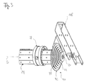
- the rotary shaft assembly 10 includes a rotary shaft 20 which is rotatably supported about two bearings 12 about a rotation axis D.
- the rotary shaft 20 has a first end 21 and a second end 22, wherein a bearing 12 is provided in the region of the first end 21 and a bearing 12 in the region of the second end 22.
- a plurality of carriers 26 are attached, to which a rotary shaft housing 24 is rotatably mounted in the form of a octagonal steel shaft.
- the driver 26 transmit the rotational movement of the rotary shaft 20 to the rotary shaft housing 24.
- rotary shaft housing 24 of the door curtain 112 is suitably mounted for winding the door curtain 112 on the rotary shaft 20 and for unwinding of the door curtain 112 of the rotary shaft 20.
- the support elements 28 and / or spring strips 29, which are explained below, are provided for the storage of the door curtain 112 during winding and unwinding.
- a drive device 120 for driving the rotary shaft 20 is provided at the second end 23 of the rotary shaft 20.
- This drive device 120 has a drive unit 122 and a transmission device 130 with a traction mechanism 132 and a traction mechanism 134.
- the relevant explanations, in particular with regard to the local authorities Figures 2 and 3 are hereby made the disclosure of the present application.
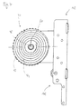
- the weight compensation device 30 comprises a winding device 40 with a conically shaped winding drum 42.
- the winding drum 42 has an outer side 44 with a spiral groove 45 having a predetermined pitch.
- the winding drum has an inner wall or inner side 48 provided by a bore 46.
- this winding device 40 with the predetermined pitch of the winding drum 42, a certain compensation characteristic for compensating the weight of the door leaf 110 is provided.
- the weight compensation device 30 has a spring unit 50 in the form of a spring assembly, which is formed from at least one inner tension spring 52 and an outer tension spring 54.
- the inner tension spring 52 is received approximately concentrically within the outer tension spring 54.
- the tension springs 52, 54 are wound in opposite directions to prevent mutual entanglement.
- the entire spring assembly is received in a cavity of the frame 104, as indicated by a dashed frame profile part in Fig. 1 is indicated.
- a first end of the spring unit 50 is connected via a spring seat with a pull hook to a stationary region of the frame 104.
- the spring unit 50 is coupled via a coupling element 60 to the winding device 40.
- the coupling element 60 comprises at least one traction means, for example in the form of a rope 62, and in particular two ropes 62, 64.
- the two ropes 62, 64 are approximately parallel, are attached with their ends to the winding drum 42 and in the groove 45 in the form of a Double groove led.
- the cables 62, 64 are wound onto the winding drum 42 or unwound from the winding drum 42.
- an adjustment of the compensation characteristic of the weight compensation device 30 is further provided, wherein the weight compensation device 30 in different positions relative to the rotational axis D positionable and rotationally fixed to the rotary shaft 20 can be fastened.
- the weight compensation device 30 can be positioned at different angular positions relative to the axis of rotation D at the latter and, after the desired setting of one of these positions, can be fastened in a rotationally fixed manner to the rotary shaft 20.
- an adjusting device 70 which provides the various positions relative to the axis of rotation D.
- the adjustment device 70 comprises a first adjustment unit 80 and a second adjustment unit 90, wherein the first adjustment unit 80 is associated with the rotary shaft 20 and the second adjustment unit 90 is associated with the weight compensation device 30 and there the winding device 40.
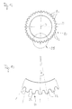
- the first adjusting unit 80 is formed by the surface configuration of the outer side 23 of the rotary shaft 20. This outer side 23 has a plurality of teeth or protrusions 82 formed by a gear structure or a tooth profile having a predetermined pitch and a predetermined pitch angle ⁇ (see FIG iguren 12, 13 ).
- the second adjustment unit 90 is formed by the surface configuration of the inside 48 of the winding drum 42.
- the inside 23 has for this purpose suitably formed recesses 92 for receiving the projections 82, wherein the recesses also according as the outer side 44 of the winding drum 42 are provided by a gear structure with a corresponding pitch and a pitch angle.
- the projections 82 and recesses 92 are engageable with each other in the form of a positive connection and disengageable.
- a frictional connection of first setting unit 80 and second setting unit 90 can be selected.
- a positive connection of the two adjusting units 80, 90 can be carried out a fast feasible and no replacement components requiring adjustment, adjustment or fine adjustment of the compensation characteristic of the weight balancing device 30.
- the rotary shaft assembly 10 by means of the support brackets 107, 108 are mounted.
- a fine adjustment of this compensation characteristic can be effected by the winding drum 42 is withdrawn from the rotary shaft 20 to a certain angle about the axis of rotation D around, for example, according to a certain number of projections 82 or recesses 92, then the winding drum 42 is pushed back in the rotated position on the rotary shaft 20 and the positive connection of projections 82 and recesses 92 a rotationally fixed connection of Rotary shaft 20 and winding drum 42 is achieved. This process can be repeated accordingly for a further adjustment or a change in the adjustment of the compensation characteristic.
- FIGS. 8 to 11 show the arrangement provided in the interior of the rotary shaft housing 24 of the rotary shaft 20 with two of the plurality of drivers 26.
- the rotary shaft 20 is formed of extruded aluminum profile and has, in particular in the region of the first end 21, a gear structure with the projections 82 on.
- the outer side 23 of the rotary shaft 20 over the entire length of this tooth structure or gear structure with the teeth or projections 82. This results in the advantage of a simple and fixed attachment of the driver 26 on the rotary shaft 20.
- the driver 26 are namely preferably made of plastic (for example, PA) and molded onto the rotary shaft 20.
- the rotary shaft 20 is introduced into a mold in such a way that a cavity corresponding to the shape of the driver 26 is formed between the rotary shaft 20 and the mold, so that subsequently the molding compound can be introduced into the mold cavity.
- the cured molding compound then forms the respective driver 26, which thus positively engages with the formation of corresponding elevations which engage in the recesses of the outer side 23 of the rotary shaft 20 formed between the projections 82 and are adhesively bonded to the rotary shaft 20 after curing of the molding compound.
- a one-piece component is provided by the rotary shaft 20 and the cohesively fastened thereon drivers 26 that can be rotatably mounted on the bearing brackets 107, 108 via the bearings 12.
- the rotary shaft housing 24 may be attached to the drivers 26.
- the traction mechanism 132 can be easily attached to the rotary shaft.
- a driver for the traction mechanism 132 is provided, which has on the inner wall of a central bore a tooth structure, which is engageable with the toothed structure of the rotary shaft 20 in engagement.
- the driver of the traction mechanism 132 can be pushed onto the rotary shaft 20.
- an additional backup can be done.
Landscapes
- Engineering & Computer Science (AREA)
- Structural Engineering (AREA)
- Architecture (AREA)
- Civil Engineering (AREA)
- Mechanical Engineering (AREA)
- Operating, Guiding And Securing Of Roll- Type Closing Members (AREA)
- Shafts, Cranks, Connecting Bars, And Related Bearings (AREA)
Applications Claiming Priority (1)
| Application Number | Priority Date | Filing Date | Title |
|---|---|---|---|
| DE102008026707.4A DE102008026707B4 (de) | 2008-06-04 | 2008-06-04 | Drehwellenanordnung für ein Tor, insbesondere für ein Rolltor, und ein solches Tor |
Publications (3)
| Publication Number | Publication Date |
|---|---|
| EP2131003A2 true EP2131003A2 (fr) | 2009-12-09 |
| EP2131003A3 EP2131003A3 (fr) | 2010-07-28 |
| EP2131003B1 EP2131003B1 (fr) | 2015-08-12 |
Family
ID=41051155
Family Applications (1)
| Application Number | Title | Priority Date | Filing Date |
|---|---|---|---|
| EP09161913.0A Active EP2131003B1 (fr) | 2008-06-04 | 2009-06-04 | Agencement d'arbres rotatifs pour une porte, notamment pour une porte roulante et une telle porte |
Country Status (2)
| Country | Link |
|---|---|
| EP (1) | EP2131003B1 (fr) |
| DE (1) | DE102008026707B4 (fr) |
Cited By (5)
| Publication number | Priority date | Publication date | Assignee | Title |
|---|---|---|---|---|
| EP2450521A2 (fr) | 2010-11-08 | 2012-05-09 | Hörmann Kg Amshausen | Elément de support pour une porte roulante ou une grille roulante |
| EP2333227A3 (fr) * | 2009-11-30 | 2013-10-02 | Hörmann Kg Amshausen | Agencement d'arbre rotatif pour un portail, notamment un portail roulant, son procédé de fabrication et portail |
| IT201800006306A1 (it) * | 2018-06-14 | 2019-12-14 | << sistema di traino per porte sezionali non bilanciate, munito di una puleggia con diametro minimale >> | |
| US20210214987A1 (en) * | 2018-06-29 | 2021-07-15 | Remorques Cft Inc. | Direct driving of doors for multi-door trailer |
| CN113597385A (zh) * | 2019-03-18 | 2021-11-02 | Hbpo有限公司 | 用于控制并引导封闭件的装置 |
Families Citing this family (1)
| Publication number | Priority date | Publication date | Assignee | Title |
|---|---|---|---|---|
| US20230417097A1 (en) * | 2022-06-23 | 2023-12-28 | Dynatect Manufacturing, Inc. | Powered door system |
Citations (4)
| Publication number | Priority date | Publication date | Assignee | Title |
|---|---|---|---|---|
| US812722A (en) | 1905-05-29 | 1906-02-13 | John Cahill | Rolling door or shutter and means for operating the same. |
| DE3005224A1 (de) | 1979-02-14 | 1980-09-04 | Le Dev De La Securite Saint Na | Hydrostatische kraftuebertragungsvorrichtung fuer ein fahrzeug, insbesondere ein brandbekaempfungsfahrzeug |
| DE4024666A1 (de) † | 1990-06-01 | 1991-12-19 | Niemetz Torbau Und Metallbau | Sektionaltor |
| DE102005049585B3 (de) † | 2005-10-17 | 2007-07-19 | Efaflex Inzeniring D.O.O. | Gewichtsausgleichseinrichtung für ein Hubtor |
Family Cites Families (6)
| Publication number | Priority date | Publication date | Assignee | Title |
|---|---|---|---|---|
| DE49843C (de) * | J. SCHMITZ in Düsseldorf, Oberstr. 26 | Aufzugsvorrichtung für Rollläden | ||
| DE3905224A1 (de) * | 1987-10-23 | 1990-08-30 | Labex Import Export Ind | Rolltor |
| US6883577B2 (en) * | 2003-02-24 | 2005-04-26 | Albany International Corp. | Rollup door with rollable door leaf |
| DE202004014167U1 (de) * | 2003-09-10 | 2005-01-13 | Weil, Lothar | Antrieb für das Torblatt eines Tores, insbesondere eines Sektionaltores |
| DE102006029913A1 (de) * | 2006-06-29 | 2008-01-03 | Erwin Laub | Rollladenantrieb |
| PL1965018T3 (pl) | 2007-03-02 | 2014-12-31 | Hoermann Kg Dissen | Brama wyposażona w mechanizm sprężynowy równoważący oraz w napęd |
-
2008
- 2008-06-04 DE DE102008026707.4A patent/DE102008026707B4/de active Active
-
2009
- 2009-06-04 EP EP09161913.0A patent/EP2131003B1/fr active Active
Patent Citations (4)
| Publication number | Priority date | Publication date | Assignee | Title |
|---|---|---|---|---|
| US812722A (en) | 1905-05-29 | 1906-02-13 | John Cahill | Rolling door or shutter and means for operating the same. |
| DE3005224A1 (de) | 1979-02-14 | 1980-09-04 | Le Dev De La Securite Saint Na | Hydrostatische kraftuebertragungsvorrichtung fuer ein fahrzeug, insbesondere ein brandbekaempfungsfahrzeug |
| DE4024666A1 (de) † | 1990-06-01 | 1991-12-19 | Niemetz Torbau Und Metallbau | Sektionaltor |
| DE102005049585B3 (de) † | 2005-10-17 | 2007-07-19 | Efaflex Inzeniring D.O.O. | Gewichtsausgleichseinrichtung für ein Hubtor |
Cited By (8)
| Publication number | Priority date | Publication date | Assignee | Title |
|---|---|---|---|---|
| EP2333227A3 (fr) * | 2009-11-30 | 2013-10-02 | Hörmann Kg Amshausen | Agencement d'arbre rotatif pour un portail, notamment un portail roulant, son procédé de fabrication et portail |
| EP2450521A2 (fr) | 2010-11-08 | 2012-05-09 | Hörmann Kg Amshausen | Elément de support pour une porte roulante ou une grille roulante |
| DE102010043530A1 (de) | 2010-11-08 | 2012-05-10 | Hörmann KG Amshausen | Auflageemelent für ein Rolltor oder Rollgitter |
| EP2450521A3 (fr) * | 2010-11-08 | 2013-08-14 | Hörmann Kg Amshausen | Elément de support pour une porte roulante ou une grille roulante |
| IT201800006306A1 (it) * | 2018-06-14 | 2019-12-14 | << sistema di traino per porte sezionali non bilanciate, munito di una puleggia con diametro minimale >> | |
| US20210214987A1 (en) * | 2018-06-29 | 2021-07-15 | Remorques Cft Inc. | Direct driving of doors for multi-door trailer |
| US11885169B2 (en) * | 2018-06-29 | 2024-01-30 | Remorques Cft Inc. | Direct driving of doors for multi-door trailer |
| CN113597385A (zh) * | 2019-03-18 | 2021-11-02 | Hbpo有限公司 | 用于控制并引导封闭件的装置 |
Also Published As
| Publication number | Publication date |
|---|---|
| EP2131003A3 (fr) | 2010-07-28 |
| DE102008026707A1 (de) | 2009-12-10 |
| EP2131003B1 (fr) | 2015-08-12 |
| DE102008026707B4 (de) | 2017-05-11 |
Similar Documents
| Publication | Publication Date | Title |
|---|---|---|
| EP1948898B1 (fr) | Porte roulante industrielle a vitesse elevee | |
| EP1954909B1 (fr) | Dispositif de compensation de poids pour porte relevable | |
| EP2131003B1 (fr) | Agencement d'arbres rotatifs pour une porte, notamment pour une porte roulante et une telle porte | |
| DE4115541A1 (de) | Rolltor, beispielsweise fuer eine garage, sowie mechanismus zum oeffnen und schliessen des rolltores | |
| DE102005013742A1 (de) | Gerät zum synchronen Aus- und Einfahren von zwei Drahtabschnitten | |
| DE2648344A1 (de) | Beschlag fuer schiebefenster, schiebetueren u.dgl. | |
| EP1965018B1 (fr) | Porte dotée d'un équilibrage du ressort de traction et dispositif d'entraînement correspondant | |
| EP2757219B1 (fr) | Dispositif d'entraînement de porte coulissante | |
| EP0864026B1 (fr) | Leve-glace a tube bowden avec compensation de longueur de cable | |
| EP2333227B1 (fr) | Agencement d'arbre rotatif pour un portail, notamment un portail roulant, son procédé de fabrication et portail | |
| CH671264A5 (fr) | ||
| EP1964700A1 (fr) | Store de fenêtre de véhicule | |
| EP1366259B1 (fr) | Porte sectionnee | |
| WO2006063565A1 (fr) | Store pour vitre de vehicule | |
| DE102007037892A1 (de) | Tor mit Zugfederausgleich sowie Antriebsvorrichtung hierfür | |
| EP3573503B1 (fr) | Dispositif d'enroulement destiné à des stores | |
| EP0150000B1 (fr) | Dispositif de manoeuvre de volet roulant comme système modulaire pour commande à gland, à manivelle et électrique | |
| DE2527843A1 (de) | Pendeltuerenantrieb | |
| DE4327230C1 (de) | Rolladen für Dachfenster | |
| DE102012210585B4 (de) | Drehtüranlage | |
| AT522526B1 (de) | Schutzrollo | |
| EP1302620A2 (fr) | Rouleau à ressort | |
| DE2716076A1 (de) | Rolladen | |
| EP1165927B1 (fr) | Dispositif d'entraínement pour porte roulante | |
| DE102008028659A1 (de) | Betätigungsanordnung für einen Schwenkflügel |
Legal Events
| Date | Code | Title | Description |
|---|---|---|---|
| PUAI | Public reference made under article 153(3) epc to a published international application that has entered the european phase |
Free format text: ORIGINAL CODE: 0009012 |
|
| AK | Designated contracting states |
Kind code of ref document: A2 Designated state(s): AT BE BG CH CY CZ DE DK EE ES FI FR GB GR HR HU IE IS IT LI LT LU LV MC MK MT NL NO PL PT RO SE SI SK TR |
|
| TPAC | Observations filed by third parties |
Free format text: ORIGINAL CODE: EPIDOSNTIPA |
|
| PUAL | Search report despatched |
Free format text: ORIGINAL CODE: 0009013 |
|
| AK | Designated contracting states |
Kind code of ref document: A3 Designated state(s): AT BE BG CH CY CZ DE DK EE ES FI FR GB GR HR HU IE IS IT LI LT LU LV MC MK MT NL NO PL PT RO SE SI SK TR |
|
| AX | Request for extension of the european patent |
Extension state: AL BA RS |
|
| RIC1 | Information provided on ipc code assigned before grant |
Ipc: E05D 13/00 20060101ALI20100618BHEP Ipc: E05F 15/16 20060101AFI20090918BHEP Ipc: E06B 9/84 20060101ALI20100618BHEP |
|
| 17P | Request for examination filed |
Effective date: 20100928 |
|
| 17Q | First examination report despatched |
Effective date: 20120531 |
|
| REG | Reference to a national code |
Ref country code: DE Ref legal event code: R079 Ref document number: 502009011395 Country of ref document: DE Free format text: PREVIOUS MAIN CLASS: E05F0015160000 Ipc: E05F0015000000 |
|
| RIC1 | Information provided on ipc code assigned before grant |
Ipc: E05F 15/686 20150101ALI20150303BHEP Ipc: E06B 9/174 20060101ALI20150303BHEP Ipc: E05F 15/00 20150101AFI20150303BHEP Ipc: E06B 9/171 20060101ALI20150303BHEP Ipc: E05D 13/00 20060101ALI20150303BHEP |
|
| GRAP | Despatch of communication of intention to grant a patent |
Free format text: ORIGINAL CODE: EPIDOSNIGR1 |
|
| INTG | Intention to grant announced |
Effective date: 20150414 |
|
| GRAS | Grant fee paid |
Free format text: ORIGINAL CODE: EPIDOSNIGR3 |
|
| GRAA | (expected) grant |
Free format text: ORIGINAL CODE: 0009210 |
|
| AK | Designated contracting states |
Kind code of ref document: B1 Designated state(s): AT BE BG CH CY CZ DE DK EE ES FI FR GB GR HR HU IE IS IT LI LT LU LV MC MK MT NL NO PL PT RO SE SI SK TR |
|
| REG | Reference to a national code |
Ref country code: GB Ref legal event code: FG4D Free format text: NOT ENGLISH |
|
| REG | Reference to a national code |
Ref country code: CH Ref legal event code: EP |
|
| REG | Reference to a national code |
Ref country code: AT Ref legal event code: REF Ref document number: 742331 Country of ref document: AT Kind code of ref document: T Effective date: 20150815 |
|
| REG | Reference to a national code |
Ref country code: IE Ref legal event code: FG4D Free format text: LANGUAGE OF EP DOCUMENT: GERMAN |
|
| REG | Reference to a national code |
Ref country code: DE Ref legal event code: R096 Ref document number: 502009011395 Country of ref document: DE |
|
| REG | Reference to a national code |
Ref country code: LT Ref legal event code: MG4D |
|
| REG | Reference to a national code |
Ref country code: NL Ref legal event code: MP Effective date: 20150812 |
|
| PG25 | Lapsed in a contracting state [announced via postgrant information from national office to epo] |
Ref country code: GR Free format text: LAPSE BECAUSE OF FAILURE TO SUBMIT A TRANSLATION OF THE DESCRIPTION OR TO PAY THE FEE WITHIN THE PRESCRIBED TIME-LIMIT Effective date: 20151113 Ref country code: FI Free format text: LAPSE BECAUSE OF FAILURE TO SUBMIT A TRANSLATION OF THE DESCRIPTION OR TO PAY THE FEE WITHIN THE PRESCRIBED TIME-LIMIT Effective date: 20150812 Ref country code: NO Free format text: LAPSE BECAUSE OF FAILURE TO SUBMIT A TRANSLATION OF THE DESCRIPTION OR TO PAY THE FEE WITHIN THE PRESCRIBED TIME-LIMIT Effective date: 20151112 Ref country code: LT Free format text: LAPSE BECAUSE OF FAILURE TO SUBMIT A TRANSLATION OF THE DESCRIPTION OR TO PAY THE FEE WITHIN THE PRESCRIBED TIME-LIMIT Effective date: 20150812 Ref country code: LV Free format text: LAPSE BECAUSE OF FAILURE TO SUBMIT A TRANSLATION OF THE DESCRIPTION OR TO PAY THE FEE WITHIN THE PRESCRIBED TIME-LIMIT Effective date: 20150812 |
|
| REG | Reference to a national code |
Ref country code: DE Ref legal event code: R082 Ref document number: 502009011395 Country of ref document: DE Representative=s name: KASTEL PATENTANWAELTE, DE Ref country code: DE Ref legal event code: R082 Ref document number: 502009011395 Country of ref document: DE Representative=s name: KASTEL PATENTANWAELTE PARTG MBB, DE |
|
| PG25 | Lapsed in a contracting state [announced via postgrant information from national office to epo] |
Ref country code: SE Free format text: LAPSE BECAUSE OF FAILURE TO SUBMIT A TRANSLATION OF THE DESCRIPTION OR TO PAY THE FEE WITHIN THE PRESCRIBED TIME-LIMIT Effective date: 20150812 Ref country code: ES Free format text: LAPSE BECAUSE OF FAILURE TO SUBMIT A TRANSLATION OF THE DESCRIPTION OR TO PAY THE FEE WITHIN THE PRESCRIBED TIME-LIMIT Effective date: 20150812 Ref country code: PL Free format text: LAPSE BECAUSE OF FAILURE TO SUBMIT A TRANSLATION OF THE DESCRIPTION OR TO PAY THE FEE WITHIN THE PRESCRIBED TIME-LIMIT Effective date: 20150812 Ref country code: HR Free format text: LAPSE BECAUSE OF FAILURE TO SUBMIT A TRANSLATION OF THE DESCRIPTION OR TO PAY THE FEE WITHIN THE PRESCRIBED TIME-LIMIT Effective date: 20150812 Ref country code: PT Free format text: LAPSE BECAUSE OF FAILURE TO SUBMIT A TRANSLATION OF THE DESCRIPTION OR TO PAY THE FEE WITHIN THE PRESCRIBED TIME-LIMIT Effective date: 20151214 Ref country code: IS Free format text: LAPSE BECAUSE OF FAILURE TO SUBMIT A TRANSLATION OF THE DESCRIPTION OR TO PAY THE FEE WITHIN THE PRESCRIBED TIME-LIMIT Effective date: 20151212 |
|
| PG25 | Lapsed in a contracting state [announced via postgrant information from national office to epo] |
Ref country code: NL Free format text: LAPSE BECAUSE OF FAILURE TO SUBMIT A TRANSLATION OF THE DESCRIPTION OR TO PAY THE FEE WITHIN THE PRESCRIBED TIME-LIMIT Effective date: 20150812 |
|
| PG25 | Lapsed in a contracting state [announced via postgrant information from national office to epo] |
Ref country code: EE Free format text: LAPSE BECAUSE OF FAILURE TO SUBMIT A TRANSLATION OF THE DESCRIPTION OR TO PAY THE FEE WITHIN THE PRESCRIBED TIME-LIMIT Effective date: 20150812 Ref country code: DK Free format text: LAPSE BECAUSE OF FAILURE TO SUBMIT A TRANSLATION OF THE DESCRIPTION OR TO PAY THE FEE WITHIN THE PRESCRIBED TIME-LIMIT Effective date: 20150812 Ref country code: SK Free format text: LAPSE BECAUSE OF FAILURE TO SUBMIT A TRANSLATION OF THE DESCRIPTION OR TO PAY THE FEE WITHIN THE PRESCRIBED TIME-LIMIT Effective date: 20150812 Ref country code: IT Free format text: LAPSE BECAUSE OF FAILURE TO SUBMIT A TRANSLATION OF THE DESCRIPTION OR TO PAY THE FEE WITHIN THE PRESCRIBED TIME-LIMIT Effective date: 20150812 Ref country code: CZ Free format text: LAPSE BECAUSE OF FAILURE TO SUBMIT A TRANSLATION OF THE DESCRIPTION OR TO PAY THE FEE WITHIN THE PRESCRIBED TIME-LIMIT Effective date: 20150812 |
|
| REG | Reference to a national code |
Ref country code: DE Ref legal event code: R097 Ref document number: 502009011395 Country of ref document: DE |
|
| PG25 | Lapsed in a contracting state [announced via postgrant information from national office to epo] |
Ref country code: RO Free format text: LAPSE BECAUSE OF FAILURE TO SUBMIT A TRANSLATION OF THE DESCRIPTION OR TO PAY THE FEE WITHIN THE PRESCRIBED TIME-LIMIT Effective date: 20150812 |
|
| PLBE | No opposition filed within time limit |
Free format text: ORIGINAL CODE: 0009261 |
|
| STAA | Information on the status of an ep patent application or granted ep patent |
Free format text: STATUS: NO OPPOSITION FILED WITHIN TIME LIMIT |
|
| REG | Reference to a national code |
Ref country code: FR Ref legal event code: PLFP Year of fee payment: 8 |
|
| 26N | No opposition filed |
Effective date: 20160513 |
|
| PG25 | Lapsed in a contracting state [announced via postgrant information from national office to epo] |
Ref country code: SI Free format text: LAPSE BECAUSE OF FAILURE TO SUBMIT A TRANSLATION OF THE DESCRIPTION OR TO PAY THE FEE WITHIN THE PRESCRIBED TIME-LIMIT Effective date: 20150812 |
|
| PG25 | Lapsed in a contracting state [announced via postgrant information from national office to epo] |
Ref country code: BE Free format text: LAPSE BECAUSE OF NON-PAYMENT OF DUE FEES Effective date: 20160630 |
|
| PG25 | Lapsed in a contracting state [announced via postgrant information from national office to epo] |
Ref country code: MC Free format text: LAPSE BECAUSE OF FAILURE TO SUBMIT A TRANSLATION OF THE DESCRIPTION OR TO PAY THE FEE WITHIN THE PRESCRIBED TIME-LIMIT Effective date: 20150812 |
|
| REG | Reference to a national code |
Ref country code: CH Ref legal event code: PL |
|
| REG | Reference to a national code |
Ref country code: IE Ref legal event code: MM4A |
|
| PG25 | Lapsed in a contracting state [announced via postgrant information from national office to epo] |
Ref country code: CH Free format text: LAPSE BECAUSE OF NON-PAYMENT OF DUE FEES Effective date: 20160630 Ref country code: LI Free format text: LAPSE BECAUSE OF NON-PAYMENT OF DUE FEES Effective date: 20160630 |
|
| PG25 | Lapsed in a contracting state [announced via postgrant information from national office to epo] |
Ref country code: IE Free format text: LAPSE BECAUSE OF NON-PAYMENT OF DUE FEES Effective date: 20160604 |
|
| REG | Reference to a national code |
Ref country code: FR Ref legal event code: PLFP Year of fee payment: 9 |
|
| PG25 | Lapsed in a contracting state [announced via postgrant information from national office to epo] |
Ref country code: HU Free format text: LAPSE BECAUSE OF FAILURE TO SUBMIT A TRANSLATION OF THE DESCRIPTION OR TO PAY THE FEE WITHIN THE PRESCRIBED TIME-LIMIT; INVALID AB INITIO Effective date: 20090604 Ref country code: CY Free format text: LAPSE BECAUSE OF FAILURE TO SUBMIT A TRANSLATION OF THE DESCRIPTION OR TO PAY THE FEE WITHIN THE PRESCRIBED TIME-LIMIT Effective date: 20150812 |
|
| REG | Reference to a national code |
Ref country code: FR Ref legal event code: PLFP Year of fee payment: 10 |
|
| PG25 | Lapsed in a contracting state [announced via postgrant information from national office to epo] |
Ref country code: MK Free format text: LAPSE BECAUSE OF FAILURE TO SUBMIT A TRANSLATION OF THE DESCRIPTION OR TO PAY THE FEE WITHIN THE PRESCRIBED TIME-LIMIT Effective date: 20150812 Ref country code: TR Free format text: LAPSE BECAUSE OF FAILURE TO SUBMIT A TRANSLATION OF THE DESCRIPTION OR TO PAY THE FEE WITHIN THE PRESCRIBED TIME-LIMIT Effective date: 20150812 Ref country code: MT Free format text: LAPSE BECAUSE OF FAILURE TO SUBMIT A TRANSLATION OF THE DESCRIPTION OR TO PAY THE FEE WITHIN THE PRESCRIBED TIME-LIMIT Effective date: 20150812 Ref country code: LU Free format text: LAPSE BECAUSE OF NON-PAYMENT OF DUE FEES Effective date: 20160604 |
|
| PG25 | Lapsed in a contracting state [announced via postgrant information from national office to epo] |
Ref country code: BG Free format text: LAPSE BECAUSE OF FAILURE TO SUBMIT A TRANSLATION OF THE DESCRIPTION OR TO PAY THE FEE WITHIN THE PRESCRIBED TIME-LIMIT Effective date: 20150812 |
|
| P01 | Opt-out of the competence of the unified patent court (upc) registered |
Effective date: 20230512 |
|
| PGFP | Annual fee paid to national office [announced via postgrant information from national office to epo] |
Ref country code: FR Payment date: 20230619 Year of fee payment: 15 |
|
| PGFP | Annual fee paid to national office [announced via postgrant information from national office to epo] |
Ref country code: AT Payment date: 20230616 Year of fee payment: 15 |
|
| PGFP | Annual fee paid to national office [announced via postgrant information from national office to epo] |
Ref country code: GB Payment date: 20230622 Year of fee payment: 15 |
|
| PGFP | Annual fee paid to national office [announced via postgrant information from national office to epo] |
Ref country code: DE Payment date: 20230822 Year of fee payment: 15 |