EP2131003A2 - Rotating shaft assembly for a door, in particular for a roller door and such a door - Google Patents
Rotating shaft assembly for a door, in particular for a roller door and such a door Download PDFInfo
- Publication number
- EP2131003A2 EP2131003A2 EP20090161913 EP09161913A EP2131003A2 EP 2131003 A2 EP2131003 A2 EP 2131003A2 EP 20090161913 EP20090161913 EP 20090161913 EP 09161913 A EP09161913 A EP 09161913A EP 2131003 A2 EP2131003 A2 EP 2131003A2
- Authority
- EP
- European Patent Office
- Prior art keywords
- rotary shaft
- door
- weight
- door leaf
- arrangement
- Prior art date
- Legal status (The legal status is an assumption and is not a legal conclusion. Google has not performed a legal analysis and makes no representation as to the accuracy of the status listed.)
- Granted
Links
- 238000004804 winding Methods 0.000 claims description 38
- 230000007246 mechanism Effects 0.000 claims description 10
- 230000005540 biological transmission Effects 0.000 claims description 8
- 230000008878 coupling Effects 0.000 claims description 8
- 238000010168 coupling process Methods 0.000 claims description 8
- 238000005859 coupling reaction Methods 0.000 claims description 8
- 238000002347 injection Methods 0.000 claims 1
- 239000007924 injection Substances 0.000 claims 1
- 238000009434 installation Methods 0.000 description 5
- 150000001875 compounds Chemical class 0.000 description 3
- 230000001419 dependent effect Effects 0.000 description 3
- 238000000465 moulding Methods 0.000 description 3
- XAGFODPZIPBFFR-UHFFFAOYSA-N aluminium Chemical compound [Al] XAGFODPZIPBFFR-UHFFFAOYSA-N 0.000 description 2
- 229910052782 aluminium Inorganic materials 0.000 description 2
- 230000008901 benefit Effects 0.000 description 2
- 230000003993 interaction Effects 0.000 description 2
- 229910000831 Steel Inorganic materials 0.000 description 1
- 230000015572 biosynthetic process Effects 0.000 description 1
- 239000000969 carrier Substances 0.000 description 1
- 230000008859 change Effects 0.000 description 1
- 239000000470 constituent Substances 0.000 description 1
- 238000010276 construction Methods 0.000 description 1
- 238000005553 drilling Methods 0.000 description 1
- 238000000034 method Methods 0.000 description 1
- 239000012778 molding material Substances 0.000 description 1
- 230000008569 process Effects 0.000 description 1
- 239000010959 steel Substances 0.000 description 1
Images


Classifications
-
- E—FIXED CONSTRUCTIONS
- E06—DOORS, WINDOWS, SHUTTERS, OR ROLLER BLINDS IN GENERAL; LADDERS
- E06B—FIXED OR MOVABLE CLOSURES FOR OPENINGS IN BUILDINGS, VEHICLES, FENCES OR LIKE ENCLOSURES IN GENERAL, e.g. DOORS, WINDOWS, BLINDS, GATES
- E06B9/00—Screening or protective devices for wall or similar openings, with or without operating or securing mechanisms; Closures of similar construction
- E06B9/02—Shutters, movable grilles, or other safety closing devices, e.g. against burglary
- E06B9/08—Roll-type closures
- E06B9/11—Roller shutters
- E06B9/17—Parts or details of roller shutters, e.g. suspension devices, shutter boxes, wicket doors, ventilation openings
- E06B9/174—Bearings specially adapted therefor
-
- E—FIXED CONSTRUCTIONS
- E05—LOCKS; KEYS; WINDOW OR DOOR FITTINGS; SAFES
- E05D—HINGES OR SUSPENSION DEVICES FOR DOORS, WINDOWS OR WINGS
- E05D13/00—Accessories for sliding or lifting wings, e.g. pulleys, safety catches
- E05D13/10—Counterbalance devices
- E05D13/12—Counterbalance devices with springs
- E05D13/1207—Counterbalance devices with springs with tension springs
- E05D13/1223—Spring safety devices
-
- E—FIXED CONSTRUCTIONS
- E05—LOCKS; KEYS; WINDOW OR DOOR FITTINGS; SAFES
- E05F—DEVICES FOR MOVING WINGS INTO OPEN OR CLOSED POSITION; CHECKS FOR WINGS; WING FITTINGS NOT OTHERWISE PROVIDED FOR, CONCERNED WITH THE FUNCTIONING OF THE WING
- E05F15/00—Power-operated mechanisms for wings
- E05F15/60—Power-operated mechanisms for wings using electrical actuators
- E05F15/603—Power-operated mechanisms for wings using electrical actuators using rotary electromotors
- E05F15/665—Power-operated mechanisms for wings using electrical actuators using rotary electromotors for vertically-sliding wings
- E05F15/668—Power-operated mechanisms for wings using electrical actuators using rotary electromotors for vertically-sliding wings for overhead wings
- E05F15/681—Power-operated mechanisms for wings using electrical actuators using rotary electromotors for vertically-sliding wings for overhead wings operated by flexible elongated pulling elements, e.g. belts
- E05F15/686—Power-operated mechanisms for wings using electrical actuators using rotary electromotors for vertically-sliding wings for overhead wings operated by flexible elongated pulling elements, e.g. belts by cables or ropes
-
- E—FIXED CONSTRUCTIONS
- E06—DOORS, WINDOWS, SHUTTERS, OR ROLLER BLINDS IN GENERAL; LADDERS
- E06B—FIXED OR MOVABLE CLOSURES FOR OPENINGS IN BUILDINGS, VEHICLES, FENCES OR LIKE ENCLOSURES IN GENERAL, e.g. DOORS, WINDOWS, BLINDS, GATES
- E06B9/00—Screening or protective devices for wall or similar openings, with or without operating or securing mechanisms; Closures of similar construction
- E06B9/02—Shutters, movable grilles, or other safety closing devices, e.g. against burglary
- E06B9/08—Roll-type closures
- E06B9/11—Roller shutters
- E06B9/17—Parts or details of roller shutters, e.g. suspension devices, shutter boxes, wicket doors, ventilation openings
- E06B9/171—Rollers therefor; Fastening roller shutters to rollers
-
- E—FIXED CONSTRUCTIONS
- E05—LOCKS; KEYS; WINDOW OR DOOR FITTINGS; SAFES
- E05Y—INDEXING SCHEME RELATING TO HINGES OR OTHER SUSPENSION DEVICES FOR DOORS, WINDOWS OR WINGS AND DEVICES FOR MOVING WINGS INTO OPEN OR CLOSED POSITION, CHECKS FOR WINGS AND WING FITTINGS NOT OTHERWISE PROVIDED FOR, CONCERNED WITH THE FUNCTIONING OF THE WING
- E05Y2900/00—Application of doors, windows, wings or fittings thereof
- E05Y2900/10—Application of doors, windows, wings or fittings thereof for buildings or parts thereof
- E05Y2900/106—Application of doors, windows, wings or fittings thereof for buildings or parts thereof for garages
Definitions
- the present invention relates to a rotary shaft arrangement for a gate, in particular for a roller shutter, with a rotating shaft about a rotation axis. Furthermore, the invention relates to a provided with such a rotary shaft assembly gate, in particular a roller door.
- the door leaf is designed, in particular, as a door curtain and comprises, for example, a multiplicity of panels or roller shutter rods which are joined together in an articulated manner and which can be rolled up around a rotary shaft designed as a winding shaft.
- a recessed in the winding shaft tubular motor or a flanged on the winding shaft worm gear motor is provided.
- spring compensations for the weight balance of the door leaf is carried out to reduce the drive power often by a arranged in the rotary or winding shaft torsion spring or by rotatably mounted on the rotary or winding coil spring packages.
- the object of the invention is to provide a rotary shaft arrangement and a gate, so that the rotary shaft arrangement or the door can be adapted in a simple manner to the mounting situation prevailing at the installation location.
- the weight compensation device can be fastened in different positions relative to the axis of rotation positionable and rotationally fixed to the rotary shaft.
- the equalizing characteristic is achieved not by exchanging the one counterbalancing device and replacing by another counterbalancing device, but by using one and the same counterbalancing device, which can be mounted in different positions relative to the rotary shaft. In this way, in order to set the optimum for the installation situation compensation characteristic of the weight balancing device, this brought into one of several available positions and then rotatably secured to the rotary shaft.
- a simple adjustment or adjustment, in particular a fine adjustment, of the compensation characteristic is possible.
- the positioning of the weight compensation device in the various positions is preferably achieved in that the weight compensation device can be positioned in different predetermined angular positions relative to the axis of rotation.
- a gear structure with a predetermined pitch can be provided for this purpose, which will be explained in more detail below.
- an adjusting device is provided, by means of which the weight compensation device is coupled to the rotary shaft, wherein the adjusting device provides the various positions relative to the axis of rotation. In each of these positions, the weight balancer can be attached to the rotary shaft. Depending on which of the available positions is selected, so can still be done some fine adjustment of the compensation characteristic.
- this adjustment means comprises a first adjustment unit and a second adjustment unit, the first adjustment unit being associated with the rotary shaft and the second adjustment unit being associated with the weight compensation device.
- the components forming the adjustment device can be assigned to different constituents of the rotary shaft arrangement and / or all can be integrated into the weight compensation device.
- the first adjustment unit and the second adjustment unit can be connected to one another by means of a non-positive connection and / or can be engaged and disengaged from one another as a positive connection.
- the first or second adjustment unit has projections and the other adjustment unit recesses in a manner such that the projections and recesses are positively connected with each other.
- the projections and / or recesses are formed by a gear structure having a predetermined pitch and / or a predetermined pitch angle.
- the pitch angle is between about 5 ° and about 20 °, in particular between about 8 ° and about 12 °.
- the rotary shaft is designed as a toothed shaft, with the projections forming the teeth and the recesses or grooves present between the projections extending parallel to the longitudinal direction of the rotary shaft or parallel to the axis of rotation.
- the weight compensation device has a winding device, in particular a conical winding drum, with a predetermined basic compensation characteristic.
- the weight compensation device can provide a basic compensation characteristic and at the same time an additional compensation characteristic due to its design and / or its interaction with the rotary shaft.
- the weight compensation device may comprise a spring unit.
- the spring unit comprises at least one tension spring.
- a plurality of mutually arranged tension springs can be provided.
- the tension springs may be substantially concentric with each other and / or be wound in opposite directions.
- the weight compensation device may comprise a coupling element, via which the spring unit is coupled to the winding device, wherein preferably the coupling element comprises at least one cable, in particular two cables.
- the coupling element comprises at least one cable, in particular two cables.
- At least one driver for transmitting the rotational movement of the rotary shaft is mounted on a rotary shaft housing.
- the driver is integrally connected to the rotary shaft.
- the driver is made of plastic and molded onto the rotary shaft.
- the rotary shaft may be formed of an aluminum extruded profile, which is introduced into a mold and then the molding material is introduced into the present between the rotary shaft and mold inside cavity for forming the driver under cohesive connection with the rotary shaft.
- the gate according to the invention in particular in the form of a roller shutter, comprises a door leaf and a rotary shaft arrangement according to the invention, wherein the rotary shaft is rotatably mounted on the door leaf and wherein the weight compensation device has a compensation characteristic for balancing the weight of the door leaf when opening and closing the door leaf.
- the gate according to the invention makes use of the advantages of the rotary shaft arrangement according to the invention, to which reference is hereby made.
- a drive unit is connected via a transmission device to the rotary shaft for rotationally driving the same, wherein the transmission device has a traction mechanism with a closed traction means to an endless loop. More preferably, the transmission device may have a self-locking worm gear.
- the worm gear preferably has a ratio of at least 1:20, preferably at least 1:60 and more preferably more than 1:80.
- the traction mechanism is designed for example as a positive traction mechanism.
- a rotary shaft housing which is non-rotatably connected via at least one driver with the rotary shaft, wherein on the rotary shaft housing a door curtain is attached as a door leaf. Furthermore, it can be provided that the door curtain is attached in a rotationally fixed manner to the rotary shaft via support elements mounted on the rotary shaft housing. Furthermore, the door curtain can be attached to the support element or to the rotary shaft housing via at least one spring band.
- the support element preferably has an at least arcuate outer surface and is used to attach the rotary shaft end of the door curtain and for storage in particular of the first rod element of the door curtain, but also the subsequent elements of the door curtain during winding and unwinding of the door curtain.
- at least one spring band can be used, which is fastened to the support element and / or the rotary shaft housing.
- a Montagezugstoff can be attached to the rotary shaft or the rotary shaft housing.
- Gate 100 is a roller door for opening and closing a building opening 102.
- Gate 100 includes a door leaf 110 having a door hanger 112 which has a plurality of hinged rods or fins 114.
- a closing profile 116 on the door curtain 112 In the area of a lower closing edge 117, which in the closed position touches the floor 103, there is a closing profile 116 on the door curtain 112, wherein the closing profile 116 may comprise, for example, a seal and / or an anti-pinch protection.
- the gate 100 is fixed by means of a frame 104 as a stationary frame member at the edge of the building opening 102.
- the frame 104 has two guide rails 105, 106 with attached support brackets 107, 108.
- the door curtain 112 When opening and closing the door 100 along the door path S, the door curtain 112 is guided with its lateral edges in the guide rails 105, 106. On the support brackets 107, 108 a rotary shaft assembly 10 is mounted.
- the rotary shaft assembly 10 is in the FIGS. 2 to 13 further illustrated and will be explained in more detail below.
- the rotary shaft assembly 10 includes a rotary shaft 20 which is rotatably supported about two bearings 12 about a rotation axis D.
- the rotary shaft 20 has a first end 21 and a second end 22, wherein a bearing 12 is provided in the region of the first end 21 and a bearing 12 in the region of the second end 22.
- a plurality of carriers 26 are attached, to which a rotary shaft housing 24 is rotatably mounted in the form of a octagonal steel shaft.
- the driver 26 transmit the rotational movement of the rotary shaft 20 to the rotary shaft housing 24.
- rotary shaft housing 24 of the door curtain 112 is suitably mounted for winding the door curtain 112 on the rotary shaft 20 and for unwinding of the door curtain 112 of the rotary shaft 20.
- the support elements 28 and / or spring strips 29, which are explained below, are provided for the storage of the door curtain 112 during winding and unwinding.
- a drive device 120 for driving the rotary shaft 20 is provided at the second end 23 of the rotary shaft 20.
- This drive device 120 has a drive unit 122 and a transmission device 130 with a traction mechanism 132 and a traction mechanism 134.
- the relevant explanations, in particular with regard to the local authorities Figures 2 and 3 are hereby made the disclosure of the present application.
- the weight compensation device 30 comprises a winding device 40 with a conically shaped winding drum 42.
- the winding drum 42 has an outer side 44 with a spiral groove 45 having a predetermined pitch.
- the winding drum has an inner wall or inner side 48 provided by a bore 46.
- this winding device 40 with the predetermined pitch of the winding drum 42, a certain compensation characteristic for compensating the weight of the door leaf 110 is provided.
- the weight compensation device 30 has a spring unit 50 in the form of a spring assembly, which is formed from at least one inner tension spring 52 and an outer tension spring 54.
- the inner tension spring 52 is received approximately concentrically within the outer tension spring 54.
- the tension springs 52, 54 are wound in opposite directions to prevent mutual entanglement.
- the entire spring assembly is received in a cavity of the frame 104, as indicated by a dashed frame profile part in Fig. 1 is indicated.
- a first end of the spring unit 50 is connected via a spring seat with a pull hook to a stationary region of the frame 104.
- the spring unit 50 is coupled via a coupling element 60 to the winding device 40.
- the coupling element 60 comprises at least one traction means, for example in the form of a rope 62, and in particular two ropes 62, 64.
- the two ropes 62, 64 are approximately parallel, are attached with their ends to the winding drum 42 and in the groove 45 in the form of a Double groove led.
- the cables 62, 64 are wound onto the winding drum 42 or unwound from the winding drum 42.
- an adjustment of the compensation characteristic of the weight compensation device 30 is further provided, wherein the weight compensation device 30 in different positions relative to the rotational axis D positionable and rotationally fixed to the rotary shaft 20 can be fastened.
- the weight compensation device 30 can be positioned at different angular positions relative to the axis of rotation D at the latter and, after the desired setting of one of these positions, can be fastened in a rotationally fixed manner to the rotary shaft 20.
- an adjusting device 70 which provides the various positions relative to the axis of rotation D.
- the adjustment device 70 comprises a first adjustment unit 80 and a second adjustment unit 90, wherein the first adjustment unit 80 is associated with the rotary shaft 20 and the second adjustment unit 90 is associated with the weight compensation device 30 and there the winding device 40.
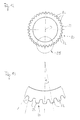
- the first adjusting unit 80 is formed by the surface configuration of the outer side 23 of the rotary shaft 20. This outer side 23 has a plurality of teeth or protrusions 82 formed by a gear structure or a tooth profile having a predetermined pitch and a predetermined pitch angle ⁇ (see FIG iguren 12, 13 ).
- the second adjustment unit 90 is formed by the surface configuration of the inside 48 of the winding drum 42.
- the inside 23 has for this purpose suitably formed recesses 92 for receiving the projections 82, wherein the recesses also according as the outer side 44 of the winding drum 42 are provided by a gear structure with a corresponding pitch and a pitch angle.
- the projections 82 and recesses 92 are engageable with each other in the form of a positive connection and disengageable.
- a frictional connection of first setting unit 80 and second setting unit 90 can be selected.
- a positive connection of the two adjusting units 80, 90 can be carried out a fast feasible and no replacement components requiring adjustment, adjustment or fine adjustment of the compensation characteristic of the weight balancing device 30.
- the rotary shaft assembly 10 by means of the support brackets 107, 108 are mounted.
- a fine adjustment of this compensation characteristic can be effected by the winding drum 42 is withdrawn from the rotary shaft 20 to a certain angle about the axis of rotation D around, for example, according to a certain number of projections 82 or recesses 92, then the winding drum 42 is pushed back in the rotated position on the rotary shaft 20 and the positive connection of projections 82 and recesses 92 a rotationally fixed connection of Rotary shaft 20 and winding drum 42 is achieved. This process can be repeated accordingly for a further adjustment or a change in the adjustment of the compensation characteristic.
- FIGS. 8 to 11 show the arrangement provided in the interior of the rotary shaft housing 24 of the rotary shaft 20 with two of the plurality of drivers 26.
- the rotary shaft 20 is formed of extruded aluminum profile and has, in particular in the region of the first end 21, a gear structure with the projections 82 on.
- the outer side 23 of the rotary shaft 20 over the entire length of this tooth structure or gear structure with the teeth or projections 82. This results in the advantage of a simple and fixed attachment of the driver 26 on the rotary shaft 20.
- the driver 26 are namely preferably made of plastic (for example, PA) and molded onto the rotary shaft 20.
- the rotary shaft 20 is introduced into a mold in such a way that a cavity corresponding to the shape of the driver 26 is formed between the rotary shaft 20 and the mold, so that subsequently the molding compound can be introduced into the mold cavity.
- the cured molding compound then forms the respective driver 26, which thus positively engages with the formation of corresponding elevations which engage in the recesses of the outer side 23 of the rotary shaft 20 formed between the projections 82 and are adhesively bonded to the rotary shaft 20 after curing of the molding compound.
- a one-piece component is provided by the rotary shaft 20 and the cohesively fastened thereon drivers 26 that can be rotatably mounted on the bearing brackets 107, 108 via the bearings 12.
- the rotary shaft housing 24 may be attached to the drivers 26.
- the traction mechanism 132 can be easily attached to the rotary shaft.
- a driver for the traction mechanism 132 is provided, which has on the inner wall of a central bore a tooth structure, which is engageable with the toothed structure of the rotary shaft 20 in engagement.
- the driver of the traction mechanism 132 can be pushed onto the rotary shaft 20.
- an additional backup can be done.
Abstract
Description
Die vorliegende Erfindung betrifft eine Drehwellenanordnung für ein Tor, insbesondere für ein Rolltor, mit einer um eine Drehachse drehbaren Drehwelle. Ferner betrifft die Erfindung ein mit einer solchen Drehwellenanordnung versehenes Tor, insbesondere ein Rolltor.The present invention relates to a rotary shaft arrangement for a gate, in particular for a roller shutter, with a rotating shaft about a rotation axis. Furthermore, the invention relates to a provided with such a rotary shaft assembly gate, in particular a roller door.
Bei Rolltoren ist das Torblatt insbesondere als Torbehang ausgebildet und umfasst beispielsweise eine Vielzahl von ineinander gelenkig zusammengefügten Paneelen oder Rolltorstäben, die um eine als Wickelwelle ausgebildete Drehwelle aufgerollt werden können. Zum Antrieb solcher Rolltore ist meist ein in der Wickelwelle eingelassener Rohrmotor oder ein auf die Wickelwelle geflanschter Schneckengetriebemotor vorgesehen. Ferner ist es bekannt, Federausgleiche für den Gewichtsausgleich des Torblattes vorzusehen. Ein solcher Federausgleich erfolgt zum Herabsetzen der Antriebsleistung oft durch eine in der Dreh- oder Wickelwelle angeordnete Drehfeder oder durch auf der Dreh- oder Wickelwelle drehbar angeordnete Spiralfederpakete.In the case of roller shutters, the door leaf is designed, in particular, as a door curtain and comprises, for example, a multiplicity of panels or roller shutter rods which are joined together in an articulated manner and which can be rolled up around a rotary shaft designed as a winding shaft. To drive such roller doors usually a recessed in the winding shaft tubular motor or a flanged on the winding shaft worm gear motor is provided. Furthermore, it is known to provide spring compensations for the weight balance of the door leaf. Such a spring compensation is carried out to reduce the drive power often by a arranged in the rotary or winding shaft torsion spring or by rotatably mounted on the rotary or winding coil spring packages.
Bei den herkömmlichen Gewichtsausgleichseinrichtungen wird beispielsweise eine Wickeltrommel mit einer vorbestimmten Steigung oder mit einer Federeinheit mit einer vorbestimmten Federcharakteristik eingesetzt. Allerdings ist es bei der Montage dann zwingend erforderlich, das Rolltor und insbesondere die Drehwellenanordnung besonders exakt zu montieren, so dass die voreingestellte Ausgleichscharakteristik erreicht wird. Allerdings ergibt sich bei der Einbaustelle oft eine mehr oder weniger abweichende Situation als vorab angenommen, so dass dann nach der Montage des Tores nicht die voreingestellte Ausgleichscharakteristik erreicht werden kann.In the conventional weight compensation devices, for example, a winding drum with a predetermined pitch or with a spring unit with a predetermined spring characteristic is used. However, it is imperative during assembly then to mount the roller shutter and in particular the rotary shaft assembly very precisely, so that the preset compensation characteristic is achieved. However, at the installation site, a more or less deviant situation often results than previously assumed, so that then after the installation of the door, the preset compensation characteristic can not be achieved.
Die Aufgabe der Erfindung besteht darin, eine Drehwellenanordnung und ein Tor zu schaffen, so dass die Drehwellenanordnung bzw. das Tor auf einfache Weise auf die am Einbauort vorherrschende Einbausituation angepasst werden kann.The object of the invention is to provide a rotary shaft arrangement and a gate, so that the rotary shaft arrangement or the door can be adapted in a simple manner to the mounting situation prevailing at the installation location.
Zur Lösung dieser Aufgabe ist eine Drehwellenanordnung mit den Merkmalen des Patentanspruchs 1 und ein Tor mit den Merkmalen des Patentanspruchs 14 vorgesehen. Vorteilhafte Ausgestaltungen der Erfindung sind Gegenstand der Unteransprüche.To solve this problem, a rotary shaft assembly with the features of
Bei einer bevorzugten Ausführungsform ist zur Verstellung der Ausgleichscharakteristik vorgesehen, dass die Gewichtsausgleichseinrichtung in verschiedenen Positionen relativ zur Drehachse positionierbar und drehfest an der Drehwelle befestigbar ist. Mit anderen Worten wird vorzugsweise die Ausgleichscharakteristik nicht durch Austauschen der einen Gewichtsausgleichseinrichtung und Ersetzen durch eine andere Gewichtsausgleichseinrichtung, sondern durch Verwendung ein und derselben Gewichtsausgleichseinrichtung erreicht, wobei diese in verschiedenen Positionen relativ zur Drehachse bzw. Drehwelle angebracht werden kann. Auf diese Weise kann, um die für die Einbausituation optimale Ausgleichscharakteristik der Gewichtsausgleichseinrichtung einzustellen, diese in eine von mehreren zur Verfügung stehenden Positionen gebracht und anschließend drehfest an der Drehwelle befestigt werden. Somit ist mittels einer einfachen Handhabung und ohne Verwendung einer Vielzahl von Bauteilen oder Einsatz von Austauschteilen eine einfache Verstellung oder Einstellung, insbesondere eine Feinjustierung, der Ausgleichscharakteristik möglich.In a preferred embodiment, it is provided for adjusting the compensation characteristic that the weight compensation device can be fastened in different positions relative to the axis of rotation positionable and rotationally fixed to the rotary shaft. In other words, preferably, the equalizing characteristic is achieved not by exchanging the one counterbalancing device and replacing by another counterbalancing device, but by using one and the same counterbalancing device, which can be mounted in different positions relative to the rotary shaft. In this way, in order to set the optimum for the installation situation compensation characteristic of the weight balancing device, this brought into one of several available positions and then rotatably secured to the rotary shaft. Thus, by means of simple handling and without the use of a plurality of components or use of replacement parts, a simple adjustment or adjustment, in particular a fine adjustment, of the compensation characteristic is possible.
Die Positionierung der Gewichtsausgleichseinrichtung in den verschiedenen Positionen wird vorzugsweise dadurch erreicht, dass die Gewichtsausgleichseinrichtung in verschiedenen vorbestimmten Winkelpositionen relativ zur Drehachse positionierbar ist. Beispielsweise kann hierfür eine Zahnradstruktur mit einer vorbestimmten Teilung vorgesehen werden, die weiter unten noch genauer erläutert wird.The positioning of the weight compensation device in the various positions is preferably achieved in that the weight compensation device can be positioned in different predetermined angular positions relative to the axis of rotation. For example, a gear structure with a predetermined pitch can be provided for this purpose, which will be explained in more detail below.
Vorteilhafterweise ist eine Einstelleinrichtung vorgesehen, mittels der die Gewichtsausgleichseinrichtung an der Drehwelle angekoppelt ist, wobei die Einstelleinrichtung die verschiedenen Positionen relativ zur Drehachse bereitstellt. In jeder dieser Positionen kann die Gewichtsausgleichseinrichtung an der Drehwelle angebracht werden. Je nachdem welche der zur Verfügung stehenden Positionen gewählt wird, kann so noch eine gewisse Feineinstellung der Ausgleichscharakteristik erfolgen.Advantageously, an adjusting device is provided, by means of which the weight compensation device is coupled to the rotary shaft, wherein the adjusting device provides the various positions relative to the axis of rotation. In each of these positions, the weight balancer can be attached to the rotary shaft. Depending on which of the available positions is selected, so can still be done some fine adjustment of the compensation characteristic.
Bei einer bevorzugten Ausführungsform umfasst diese Einstelleinrichtung eine erste Einstelleinheit und eine zweite Einstelleinheit, wobei die erste Einstelleinheit der Drehwelle und die zweite Einstelleinheit der Gewichtsausgleichseinrichtung zugeordnet ist. Mit anderen Worten können die die Einstelleinrichtung bildenden Bauteile verschiedenen Bestandteilen der Drehwellenanordnung zugeordnet sein und/oder alle in die Gewichtsausgleichseinrichtung integriert sein.In a preferred embodiment, this adjustment means comprises a first adjustment unit and a second adjustment unit, the first adjustment unit being associated with the rotary shaft and the second adjustment unit being associated with the weight compensation device. In other words, the components forming the adjustment device can be assigned to different constituents of the rotary shaft arrangement and / or all can be integrated into the weight compensation device.
Hinsichtlich des Zusammenwirkens von erster und zweiter Einstelleinheit ist vorzugsweise vorgesehen, dass die erste Einstelleinheit und die zweite Einstelleinheit mittels einer kraftschlüssigen Verbindung miteinander verbindbar sind und/oder als formschlüssige Verbindung miteinander in Eingriff und außer Eingriff bringbar sind. In bevorzugter Ausgestaltung weist die erste oder zweite Einstelleinheit Vorsprünge und die andere Einstelleinheit Ausnehmungen in einer Weise auf, so dass die Vorsprünge und Ausnehmungen formschlüssig miteinander verbindbar sind. Vorteilhafterweise sind die Vorsprünge und/oder Ausnehmungen durch eine Zahnradstruktur mit einer vorbestimmten Teilung und/oder einem vorbestimmten Teilungswinkel gebildet. Vorzugsweise beträgt der Teilungswinkel zwischen etwa 5° und etwa 20°, insbesondere zwischen etwa 8° und etwa 12°. Besonders bevorzugt ist die Drehwelle als Zahnwelle ausgebildet, wobei sich die die Zähne bildenden Vorsprünge und die zwischen den Vorsprüngen vorhandenen Ausnehmungen oder Nuten parallel zur Längsrichtung der Drehwelle beziehungsweise parallel zur Drehachse erstrecken.With regard to the interaction of the first and second adjustment unit, it is preferably provided that the first adjustment unit and the second adjustment unit can be connected to one another by means of a non-positive connection and / or can be engaged and disengaged from one another as a positive connection. In a preferred embodiment, the first or second adjustment unit has projections and the other adjustment unit recesses in a manner such that the projections and recesses are positively connected with each other. Advantageously, the projections and / or recesses are formed by a gear structure having a predetermined pitch and / or a predetermined pitch angle. Preferably, the pitch angle is between about 5 ° and about 20 °, in particular between about 8 ° and about 12 °. Particularly preferably, the rotary shaft is designed as a toothed shaft, with the projections forming the teeth and the recesses or grooves present between the projections extending parallel to the longitudinal direction of the rotary shaft or parallel to the axis of rotation.
Gemäß einer vorteilhaften Ausgestaltung weist die Gewichtsausgleichseinrichtung eine Wickeleinrichtung, insbesondere eine konische Wickeltrommel, mit einer vorbestimmten Grundausgleichscharakteristik auf. Mit anderen Worten kann die Gewichtsausgleichseinrichtung durch ihre Bauart und/oder ihr Zusammenwirken mit der Drehwelle eine Grundausgleichscharakteristik und zugleich eine Zusatzausgleichscharakteristik bereitstellen. Infolge der vorzugsweise mittels der Einstelleinrichtung verstellbaren Zusatzausgleichscharakteristik kann die Feinjustierung der Gesamtausgleichscharakteristik erfolgen.According to an advantageous embodiment, the weight compensation device has a winding device, in particular a conical winding drum, with a predetermined basic compensation characteristic. In other words, the weight compensation device can provide a basic compensation characteristic and at the same time an additional compensation characteristic due to its design and / or its interaction with the rotary shaft. As a result of the adjustable by means of the adjustment additional compensation characteristic, the fine adjustment of the overall compensation characteristic can be carried out.
Ferner kann die Gewichtsausgleichseinrichtung eine Federeinheit aufweisen. Vorzugsweise umfasst die Federeinheit wenigstens eine Zugfeder. Beispielsweise können mehrere ineinander angeordnete Zugfedern vorgesehen werden. Die Zugfedern können im Wesentlichen konzentrisch zueinander angeordnet und/oder gegenläufig zueinander gewickelt sein.Furthermore, the weight compensation device may comprise a spring unit. Preferably, the spring unit comprises at least one tension spring. For example, a plurality of mutually arranged tension springs can be provided. The tension springs may be substantially concentric with each other and / or be wound in opposite directions.
Weiterhin kann die Gewichtsausgleichseinrichtung ein Koppelelement aufweisen, über das die Federeinheit an die Wickeleinrichtung gekoppelt ist, wobei vorzugsweise das Koppelelement wenigstens ein Seil, insbesondere zwei Seile, umfasst. Diese mehreren Seile können im Wesentlichen parallel zueinander geführt sein und vorzugsweise durch Zugseile, insbesondere Drahtseile, gebildet werden.Furthermore, the weight compensation device may comprise a coupling element, via which the spring unit is coupled to the winding device, wherein preferably the coupling element comprises at least one cable, in particular two cables. These multiple ropes can be essentially parallel be guided to each other and preferably by tension cables, in particular wire ropes, are formed.
Bei einer weiteren bevorzugten Ausführungsform ist wenigstens ein Mitnehmer zur Übertragung der Drehbewegung der Drehwelle auf ein Drehwellengehäuse angebracht. Vorzugsweise ist der Mitnehmer stoffschlüssig mit der Drehwelle verbunden. Beispielsweise ist der Mitnehmer aus Kunststoff gefertigt und an die Drehwelle angespritzt. Beispielsweise kann die Drehwelle aus einem Aluminium-Strangprofil gebildet sein, das in ein Formwerkzeug eingebracht wird und dann die Formmasse in den zwischen Drehwelle und Formwerkzeuginnenseite vorhandenen Hohlraum zur Ausbildung des Mitnehmers unter stoffschlüssiger Verbindung mit der Drehwelle eingebracht wird.In a further preferred embodiment, at least one driver for transmitting the rotational movement of the rotary shaft is mounted on a rotary shaft housing. Preferably, the driver is integrally connected to the rotary shaft. For example, the driver is made of plastic and molded onto the rotary shaft. For example, the rotary shaft may be formed of an aluminum extruded profile, which is introduced into a mold and then the molding material is introduced into the present between the rotary shaft and mold inside cavity for forming the driver under cohesive connection with the rotary shaft.
Das erfindungsgemäße Tor, insbesondere in Form eines Rolltores, umfasst ein Torblatt und eine erfindungsgemäße Drehwellenanordnung, wobei die Drehwelle drehfest an dem Torblatt angebracht ist und wobei die Gewichtsausgleichseinrichtung eine Ausgleichscharakteristik zum Ausgleich des Gewichts des Torblattes beim Öffnen und Schließen des Torblattes aufweist. Das erfindungsgemäße Tor macht sich die Vorteile der erfindungsgemäßen Drehwellenanordnung zu Nutze, auf welche hiermit verwiesen wird.The gate according to the invention, in particular in the form of a roller shutter, comprises a door leaf and a rotary shaft arrangement according to the invention, wherein the rotary shaft is rotatably mounted on the door leaf and wherein the weight compensation device has a compensation characteristic for balancing the weight of the door leaf when opening and closing the door leaf. The gate according to the invention makes use of the advantages of the rotary shaft arrangement according to the invention, to which reference is hereby made.
Bei einer bevorzugten Ausgestaltungsform ist ein Antriebsaggregat über eine Getriebevorrichtung an die Drehwelle zum drehenden Antreiben derselben angeschlossen, wobei die Getriebevorrichtung ein Zugmittelgetriebe mit einem zu einer Endlosschleife geschlossenen Zugmittel aufweist. Weiter bevorzugt kann die Getriebevorrichtung ein selbsthemmendes Schneckengetriebe aufweisen. Das Schneckengetriebe hat vorzugsweise eine Übersetzung von wenigstens 1:20, vorzugsweise wenigstens 1:60 und weiter vorzugsweise von mehr als 1:80. Das Zugmittelgetriebe ist beispielsweise als formschlüssiges Zugmittelgetriebe ausgebildet.In a preferred embodiment, a drive unit is connected via a transmission device to the rotary shaft for rotationally driving the same, wherein the transmission device has a traction mechanism with a closed traction means to an endless loop. More preferably, the transmission device may have a self-locking worm gear. The worm gear preferably has a ratio of at least 1:20, preferably at least 1:60 and more preferably more than 1:80. The traction mechanism is designed for example as a positive traction mechanism.
Gemäß einer weiteren bevorzugten Ausgestaltung ist ein Drehwellengehäuse vorgesehen, das drehfest über wenigstens einen Mitnehmer mit der Drehwelle verbunden ist, wobei an dem Drehwellengehäuse ein Torbehang als Torblatt angebracht ist. Weiterhin kann vorgesehen sein, dass der Torbehang über an dem Drehwellengehäuse angebrachte Auflageelemente drehfest an der Drehwelle befestigt ist. Ferner kann der Torbehang über wenigstens ein Federband an dem Auflageelement oder an dem Drehwellengehäuse befestigt ist.According to a further preferred embodiment, a rotary shaft housing is provided which is non-rotatably connected via at least one driver with the rotary shaft, wherein on the rotary shaft housing a door curtain is attached as a door leaf. Furthermore, it can be provided that the door curtain is attached in a rotationally fixed manner to the rotary shaft via support elements mounted on the rotary shaft housing. Furthermore, the door curtain can be attached to the support element or to the rotary shaft housing via at least one spring band.
Das Auflageelement weist vorzugsweise eine zumindest bogenförmige Außenfläche auf und dient zur Befestigung des drehwellenseitigen Endes des Torbehanges sowie zur Lagerung insbesondere des ersten Stabelementes des Torbehanges, aber auch der darauffolgenden Elemente des Torbehanges beim Auf- und Abwickeln des Torbehanges. Zur Befestigung des drehwellenseitigen Endes des Torbehanges kann wenigstens ein Federband verwendet werden, das an den Auflageelement und/oder dem Drehwellengehäuse befestigt ist. Weiterhin erweist es sich als vorteilhaft, wenn mehrere Auflageelemente vorgesehen werden und zwischen diesen Auflageelementen ein Montagezugmittel an der Drehwelle bzw. dem Drehwellengehäuse angebracht werden kann. So dienen die Auflageelemente, wie oben beschrieben, zur Abstützung des Torbehanges, und die nach abgeschlossener Montage des Torbehanges an der Drehwelle vollständig aufgewickelten Montagezugbänder können als federnde Lagerelemente für den Torbehang dienen.The support element preferably has an at least arcuate outer surface and is used to attach the rotary shaft end of the door curtain and for storage in particular of the first rod element of the door curtain, but also the subsequent elements of the door curtain during winding and unwinding of the door curtain. For attachment of the rotary shaft-side end of the door curtain, at least one spring band can be used, which is fastened to the support element and / or the rotary shaft housing. Furthermore, it proves to be advantageous if a plurality of support elements are provided and between these support elements a Montagezugmittel can be attached to the rotary shaft or the rotary shaft housing. Thus, the support elements, as described above, serve to support the door curtain, and after completion of installation of the door curtain on the rotary shaft completely wound Montagezugbänder can serve as a resilient bearing elements for the door curtain.
Ausführungsbeispiele der Erfindung werden nachfolgend unter Bezugnahme auf die Zeichnungen weiter erläutert. Dabei zeigen schematisch:
- Fig. 1
- eine Innenansicht auf ein Rolltor mit Antriebsvorrichtung und Gewichtsausgleichseinrichtung;
- Fig. 2
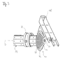
- eine perspektivische Ansicht einer Drehwellenanordnung für das Rolltor gemäß
Fig. 1 ; - Fig. 3
- eine vergrößerte Darstellung des rechtsseitigen Endbereiches der Drehwellenanordnung gemäß
Fig. 2 ; - Fig. 4
- eine Ansicht der Drehwellenanordnung gemäß
Fig. 2 ; - Fig. 5
- ein Längsschnitt durch die Drehwellenanordnung gemäß der Linie V-V in
Fig. 4 ; - Fig. 6
- ein Querschnitt gemäß der Linie VI-VI in
Fig. 4 ; - Fig. 7
- eine Ansicht des in
Fig. 4 rechtsseitigen Endes der Drehwellenanordnung; - Fig. 8
- eine perspektivische Ansicht eines Abschnittes der Drehwelle mit zwei Mitnehmern;
- Fig. 9
- eine Ansicht auf die Anordnung gemäß
Fig. 8 ; - Fig. 10
- einen Längsschnitt durch die Anordnung gemäß
Fig. 8 ; - Fig. 11
- eine Ansicht auf das in
Fig. 10 rechtsseitige Ende der Anordnung; - Fig. 12
- eine Seitenansicht eines Endes der Drehwelle, und
- Fig. 13
- eine vergrößerte Darstellung des Details XIII in
Fig. 12 .
- Fig. 1
- an inside view of a roller shutter with drive device and weight compensation device;
- Fig. 2
- a perspective view of a rotary shaft assembly for the roller door according to
Fig. 1 ; - Fig. 3
- an enlarged view of the right side end portion of the rotary shaft assembly according to
Fig. 2 ; - Fig. 4
- a view of the rotary shaft assembly according to
Fig. 2 ; - Fig. 5
- a longitudinal section through the rotary shaft assembly according to the line VV in
Fig. 4 ; - Fig. 6
- a cross section according to the line VI-VI in
Fig. 4 ; - Fig. 7
- a view of the in
Fig. 4 right-hand end of the rotary shaft assembly; - Fig. 8
- a perspective view of a portion of the rotary shaft with two drivers;
- Fig. 9
- a view of the arrangement according to
Fig. 8 ; - Fig. 10
- a longitudinal section through the arrangement according to
Fig. 8 ; - Fig. 11
- a view on the in
Fig. 10 right-hand end of the arrangement; - Fig. 12
- a side view of one end of the rotary shaft, and
- Fig. 13
- an enlarged view of detail XIII in
Fig. 12 ,
Bei dem in
Die Drehwellenanordnung 10 umfasst eine Drehwelle 20, die über zwei Lager 12 um eine Drehachse D drehbar gelagert ist. Hierbei weist die Drehwelle 20 ein erstes Ende 21 und ein zweites Ende 22 auf, wobei ein Lager 12 im Bereich des ersten Endes 21 und ein Lager 12 im Bereich des zweiten Endes 22 vorgesehen ist. An der Drehwelle 20 sind mehrere Mitnehmer 26 angebracht, an welchen ein Drehwellengehäuse 24 in Form einer Achtkantstahlwelle drehfest befestigt ist. Die Mitnehmer 26 übertragen die Drehbewegung der Drehwelle 20 auf das Drehwellengehäuse 24. An diesem Drehwellengehäuse 24 ist der Torbehang 112 in geeigneter Weise zum Aufwickeln des Torbehanges 112 auf die Drehwelle 20 sowie zum Abwickeln des Torbehangs 112 von der Drehwelle 20 angebracht. Für die Lagerung des Torbehanges 112 während des Auf- und Abwickelns sind die weiter unten noch erläuterten Auflageelemente 28 und/oder Federbänder 29 vorgesehen.The
Um eine Drehbewegung der Drehwelle 20 zu erzeugen, ist an dem zweiten Ende 23 der Drehwelle 20 eine Antriebsvorrichtung 120 zum Antreiben der Drehwelle 20 vorgesehen. Diese Antriebsvorrichtung 120 weist ein Antriebsaggregat 122 und eine Getriebevorrichtung 130 mit einem Zugmittelgetriebe 132 und einem Zugmittel 134 auf. Hinsichtlich des genauen Aufbaus und der Funktionsweise der Antriebsvorrichtung 120 wird auf die diesbezüglichen Ausführungen in der europäischen Patentanmeldung mit dem amtlichen Aktenzeichen
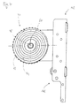
Im Bereich des ersten Endes 21 der Drehwelle 20 greift eine Gewichtsausgleichseinrichtung 30 an der Drehwelle 20 an. Im vorliegenden Ausführungsbeispiel umfasst die Gewichtsausgleichseinrichtung 30 eine Wickeleinrichtung 40 mit einer konisch geformten Wickeltrommel 42. Die Wickeltrommel 42 hat eine Aussenseite 44 mit einer spiralförmig verlaufenden Rille 45, die eine vorbestimmte Steigung aufweist. Ferner hat die Wickeltrommel eine durch eine Bohrung 46 bereitgestellte Innenwandung oder Innenseite 48.In the region of the
Insbesondere durch diese Wickeleinrichtung 40 mit der vorgegebenen Steigung der Wickeltrommel 42 wird eine bestimmte Ausgleichscharakteristik zum Ausgleich des Gewichts des Torblattes 110 bereitgestellt.In particular, by this winding
Darüber hinaus weist die Gewichtsausgleichseinrichtung 30 eine Federeinheit 50 in Form eines Federpaketes auf, das aus wenigstens einer inneren Zugfeder 52 und einer äußeren Zugfeder 54 gebildet ist. Die innere Zugfeder 52 ist innerhalb der äußeren Zugfeder 54 etwa konzentrisch aufgenommen. Die Zugfedern 52, 54 sind gegenläufig gewickelt, um ein gegenseitiges Verhaken zu verhindern. Das gesamte Federpaket ist in einem Hohlraum der Zarge 104 aufgenommen, wie dies durch ein gestrichelt dargestelltes Zargenprofilteil in
Ein erstes Ende der Federeinheit 50 ist über einen Federsitz mit einem Zughaken an einem ortsfesten Bereich der Zarge 104 angeschlossen. An seinem zweiten Ende ist die Federeinheit 50 über ein Koppelelement 60 mit der Wickeleinrichtung 40 gekoppelt. Das Koppelelement 60 umfasst wenigstens ein Zugmittel, beispielsweise in Form eines Seils 62, und insbesondere zwei Seile 62, 64. Die beiden Seile 62, 64 verlaufen etwa parallel, sind mit ihren Enden an der Wickeltrommel 42 befestigt und in der Rille 45 in Form einer Doppelrille geführt. Beim Auf- und Abwickeln des Torbehanges 112 werden die Seile 62, 64 auf die Wickeltrommel 42 aufgewickelt oder von der Wickeltrommel 42 abgewickelt.A first end of the spring unit 50 is connected via a spring seat with a pull hook to a stationary region of the
Infolge der oben erläuterten Bauweise der Gewichtsausgleichseinrichtung 30 mit Wickeleinrichtung 40, Federeinheit 50 und Koppelelement 60 und deren weiteren Bestandteilen wird die Zugkraft der Zugfedern 52, 54 insbesondere über den sich aus der jeweiligen Position der Wickeltrommel 42 ergebenden Hebelarm als ein Drehmoment auf die Wickelwelle 20 aufgebracht. Aufgrund der Steigung der Wickeltrommel 42 und die sich dadurch unterschiedlich ergebenden Hebelarme ist das durch die Zugkraft verursachte Drehmoment von der Stellung bzw. Position der Drehwelle 20 abhängig. Das jeweilige Drehmoment wirkt dem durch das Torblatt 110 in dessen verschiedenen Stellungen zwischen der geöffneten und geschlossenen Stellung wegabhängigen Drehmoment des Torblattes 110 entgegen, wodurch eine weitgehenden Kompensation der auftretenden Drehmomente erreicht wird. Diese beiden entgegenwirkenden Drehmomente bewirken eine für das jeweilige Tor charakteristische Ausgleichscharakteristik. Je geringer der sich ergebende Unterschied aus der Drehmomentkompensation ist, umso weniger leistungsstark kann eine weiter unten noch erläuterte Antriebsvorrichtung 120 des Tores 100 ausgebildet werden.As a result of the above-described construction of the
Hinsichtlich der Wirkungsweise der Gewichtsausgleichseinrichtung 30 mit der Ausgleichscharakteristik wird auf die diesbezüglichen Ausführungen in der europäischen Patentanmeldung mit dem amtlichen Aktenzeichen
Bei der in den
Zu diesem Zweck ist eine Einstelleinrichtung 70 vorgesehen, die die verschiedenen Positionen relativ zur Drehachse D bereitstellt. Die Einstelleinrichtung 70 umfasst eine erste Einstelleinheit 80 und eine zweite Einstelleinheit 90, wobei die erste Einstelleinheit 80 der Drehwelle 20 und die zweite Einstelleinheit 90 der Gewichtsausgleichseinrichtung 30 und dort der Wickeleinrichtung 40 zugeordnet ist. Die erste Einstelleinheit 80 wird durch die Oberflächenausgestaltung der Aussenseite 23 der Drehwelle 20 gebildet. Diese Aussenseite 23 weist eine Vielzahl von Zähnen oder Vorsprüngen 82 auf, die durch eine Zahnradstruktur oder ein Zahnprofil mit einer vorbestimmten Teilung und einem vorbestimmten Teilungswinkel α gebildet sind (siehe F
So kann nach der Montage der Zarge 104 mit den Führungsschienen 105, 106 die Drehwellenanordnung 10 mittels der Tragkonsolen 107, 108 montiert werden. Für den Fall, dass dann festgestellt wird, dass die Gewichtsausgleichseinrichtung 30 noch nicht die gewünschte Ausgleichscharakteristik für einen optimalen Ausgleich des Gewichts des Torblattes 110 hat, kann eine Feinjustierung dieser Ausgleichcharakteristik dadurch erfolgen, dass die Wickeltrommel 42 von der Drehwelle 20 abgezogen wird, um einen bestimmten Winkel um die Drehachse D herum, beispielsweise entsprechend einer bestimmten Anzahl von Vorsprüngen 82 oder Ausnehmungen 92, anschließend die Wickeltrommel 42 in der verdrehten Position wieder auf die Drehwelle 20 aufgeschoben wird und durch die formschlüssige Verbindung von Vorsprüngen 82 und Ausnehmungen 92 eine drehfeste Verbindung von Drehwelle 20 und Wickeltrommel 42 erreicht wird. Dieser Vorgang kann für eine weitere Justierung oder eine Änderung der Justierung der Ausgleichscharakteristik entsprechend wiederholt werden.Thus, after assembly of the
Die
- 1010
- DrehwellenanordnungRotating shaft assembly
- 1212
- Lagercamp
- 2020
- Drehwellerotary shaft
- 2121
- erstes Endefirst end
- 2222
- zweites Endesecond end
- 2323
- Aussenseiteoutside
- 2424
- DrehwellengehäuseSwivel casing
- 2626
- Mitnehmertakeaway
- 2828
- Auflageelementsupport element
- 3030
- GewichtsausgleichseinrichtungWeight balancer
- 4040
- Wickeleinrichtungwinding device
- 4242
- Wickeltrommelwinding drum
- 4444
- Aussenseiteoutside
- 4545
- Rillegroove
- 4646
- Bohrungdrilling
- 4848
- Innenseiteinside
- 5050
- Federeinheitspring unit
- 5252
- innere Zugfederinner tension spring
- 5454
- äußere Zugfederouter tension spring
- 6060
- Koppelelementcoupling element
- 6262
- Seilrope
- 6464
- Seilrope
- 7070
- Einstelleinrichtungadjustment
- 8080
- erste Einstelleinheitfirst adjustment unit
- 8282
- Vorsprunghead Start
- 9090
- zweite Einstelleinheitsecond adjustment unit
- 9292
- Ausnehmungrecess
- 100100
- Torgate
- 102102
- Gebäudeöffnungbuilding opening
- 103103
- Bodenground
- 104104
- Zargeframe
- 105105
- Führungsschieneguide rail
- 106106
- Führungsschieneguide rail
- 107107
- Tragkonsolesupport bracket
- 108108
- Tragkonsolesupport bracket
- 110110
- Torblattdoor leaf
- 112112
- TorbehangDoor curtain
- 114114
- Stäberods
- 116116
- AbschlussprofilEnd profile
- 117117
- Schließkanteclosing edge
- 120120
- Antriebsvorrichtungdriving device
- 122122
- Antriebsaggregatpower unit
- 130130
- Getriebevorrichtungtransmission device
- 132132
- Zugmittelgetriebetraction drives
- 134134
- Zugmitteltraction means
- SS
- Torwegtorweg
- DD
- Drehachseaxis of rotation
- αα
- Teilungswinkelpitch angle
Claims (17)
Applications Claiming Priority (1)
| Application Number | Priority Date | Filing Date | Title |
|---|---|---|---|
| DE102008026707.4A DE102008026707B4 (en) | 2008-06-04 | 2008-06-04 | Rotary shaft arrangement for a gate, in particular for a roller door, and such a gate |
Publications (3)
| Publication Number | Publication Date |
|---|---|
| EP2131003A2 true EP2131003A2 (en) | 2009-12-09 |
| EP2131003A3 EP2131003A3 (en) | 2010-07-28 |
| EP2131003B1 EP2131003B1 (en) | 2015-08-12 |
Family
ID=41051155
Family Applications (1)
| Application Number | Title | Priority Date | Filing Date |
|---|---|---|---|
| EP09161913.0A Active EP2131003B1 (en) | 2008-06-04 | 2009-06-04 | Rotating shaft assembly for a door, in particular for a roller door and such a door |
Country Status (2)
| Country | Link |
|---|---|
| EP (1) | EP2131003B1 (en) |
| DE (1) | DE102008026707B4 (en) |
Cited By (5)
| Publication number | Priority date | Publication date | Assignee | Title |
|---|---|---|---|---|
| EP2450521A2 (en) | 2010-11-08 | 2012-05-09 | Hörmann Kg Amshausen | Overlay element for a rolling gate or rolling grille |
| EP2333227A3 (en) * | 2009-11-30 | 2013-10-02 | Hörmann Kg Amshausen | Rotating shaft assembly for a gate, in particular for a rolling gate, a method for producing same and gate |
| IT201800006306A1 (en) * | 2018-06-14 | 2019-12-14 | << TRAILING SYSTEM FOR UNBALANCED SECTIONAL DOORS, EQUIPPED WITH A PULLEY WITH MINIMAL DIAMETER >> | |
| US20210214987A1 (en) * | 2018-06-29 | 2021-07-15 | Remorques Cft Inc. | Direct driving of doors for multi-door trailer |
| CN113597385A (en) * | 2019-03-18 | 2021-11-02 | Hbpo有限公司 | Device for controlling and guiding closures |
Families Citing this family (1)
| Publication number | Priority date | Publication date | Assignee | Title |
|---|---|---|---|---|
| US20230417097A1 (en) * | 2022-06-23 | 2023-12-28 | Dynatect Manufacturing, Inc. | Powered door system |
Citations (4)
| Publication number | Priority date | Publication date | Assignee | Title |
|---|---|---|---|---|
| US812722A (en) | 1905-05-29 | 1906-02-13 | John Cahill | Rolling door or shutter and means for operating the same. |
| DE3005224A1 (en) | 1979-02-14 | 1980-09-04 | Le Dev De La Securite Saint Na | HYDROSTATIC POWER TRANSMISSION DEVICE FOR A VEHICLE, ESPECIALLY A FIRE FIGHTING VEHICLE |
| DE4024666A1 (en) † | 1990-06-01 | 1991-12-19 | Niemetz Torbau Und Metallbau | VErtically sliding sectional door - has cable attached to each side of door with free ends of cables joining together |
| DE102005049585B3 (en) † | 2005-10-17 | 2007-07-19 | Efaflex Inzeniring D.O.O. | Weight balancing device for a lifting gate |
Family Cites Families (6)
| Publication number | Priority date | Publication date | Assignee | Title |
|---|---|---|---|---|
| DE49843C (en) * | J. SCHMITZ in Düsseldorf, Oberstr. 26 | Lifting device for roller shutters | ||
| DE3905224A1 (en) * | 1987-10-23 | 1990-08-30 | Labex Import Export Ind | ROLLING GATE |
| US6883577B2 (en) * | 2003-02-24 | 2005-04-26 | Albany International Corp. | Rollup door with rollable door leaf |
| DE202004014167U1 (en) * | 2003-09-10 | 2005-01-13 | Weil, Lothar | Compact servo drive for roller shutter door with a tube mounted motor fastened to a drive shaft fitted with cable reels and a torsion spring |
| DE102006029913A1 (en) * | 2006-06-29 | 2008-01-03 | Erwin Laub | Roller blind for winding on winding shaft, has drive spring coupled with hollow winding shaft and arranged on side between shaft and blind cabinet or in shaft, where side is turned away from engine |
| PL1965018T3 (en) | 2007-03-02 | 2014-12-31 | Hoermann Kg Dissen | Door with tension spring compensation and drive device for this purpose |
-
2008
- 2008-06-04 DE DE102008026707.4A patent/DE102008026707B4/en active Active
-
2009
- 2009-06-04 EP EP09161913.0A patent/EP2131003B1/en active Active
Patent Citations (4)
| Publication number | Priority date | Publication date | Assignee | Title |
|---|---|---|---|---|
| US812722A (en) | 1905-05-29 | 1906-02-13 | John Cahill | Rolling door or shutter and means for operating the same. |
| DE3005224A1 (en) | 1979-02-14 | 1980-09-04 | Le Dev De La Securite Saint Na | HYDROSTATIC POWER TRANSMISSION DEVICE FOR A VEHICLE, ESPECIALLY A FIRE FIGHTING VEHICLE |
| DE4024666A1 (en) † | 1990-06-01 | 1991-12-19 | Niemetz Torbau Und Metallbau | VErtically sliding sectional door - has cable attached to each side of door with free ends of cables joining together |
| DE102005049585B3 (en) † | 2005-10-17 | 2007-07-19 | Efaflex Inzeniring D.O.O. | Weight balancing device for a lifting gate |
Cited By (8)
| Publication number | Priority date | Publication date | Assignee | Title |
|---|---|---|---|---|
| EP2333227A3 (en) * | 2009-11-30 | 2013-10-02 | Hörmann Kg Amshausen | Rotating shaft assembly for a gate, in particular for a rolling gate, a method for producing same and gate |
| EP2450521A2 (en) | 2010-11-08 | 2012-05-09 | Hörmann Kg Amshausen | Overlay element for a rolling gate or rolling grille |
| DE102010043530A1 (en) | 2010-11-08 | 2012-05-10 | Hörmann KG Amshausen | Support for a roller shutter or rolling grille |
| EP2450521A3 (en) * | 2010-11-08 | 2013-08-14 | Hörmann Kg Amshausen | Overlay element for a rolling gate or rolling grille |
| IT201800006306A1 (en) * | 2018-06-14 | 2019-12-14 | << TRAILING SYSTEM FOR UNBALANCED SECTIONAL DOORS, EQUIPPED WITH A PULLEY WITH MINIMAL DIAMETER >> | |
| US20210214987A1 (en) * | 2018-06-29 | 2021-07-15 | Remorques Cft Inc. | Direct driving of doors for multi-door trailer |
| US11885169B2 (en) * | 2018-06-29 | 2024-01-30 | Remorques Cft Inc. | Direct driving of doors for multi-door trailer |
| CN113597385A (en) * | 2019-03-18 | 2021-11-02 | Hbpo有限公司 | Device for controlling and guiding closures |
Also Published As
| Publication number | Publication date |
|---|---|
| DE102008026707A1 (en) | 2009-12-10 |
| EP2131003A3 (en) | 2010-07-28 |
| EP2131003B1 (en) | 2015-08-12 |
| DE102008026707B4 (en) | 2017-05-11 |
Similar Documents
| Publication | Publication Date | Title |
|---|---|---|
| EP1948898B1 (en) | High-speed industrial roller gate | |
| EP1954909B1 (en) | Weight compensation device for a lifting gate | |
| EP2131003B1 (en) | Rotating shaft assembly for a door, in particular for a roller door and such a door | |
| DE4115541A1 (en) | ROLLER GATE, EXAMPLE FOR A GARAGE, AND MECHANISM FOR OPENING AND CLOSING THE ROLLER GATE | |
| DE102005013742A1 (en) | Device for the synchronous extension and retraction of two wire sections | |
| DE2648344A1 (en) | FITTINGS FOR SLIDING WINDOWS, SLIDING DOORS, ETC. | |
| EP1965018B1 (en) | Door with tension spring compensation and drive device for this purpose | |
| EP2757219B1 (en) | Drive device for a sliding door | |
| EP0864026B1 (en) | Bowden tube window winder with compensation for cable length | |
| EP2333227B1 (en) | Rotating shaft assembly for a gate, in particular for a rolling gate, a method for producing same and gate | |
| CH671264A5 (en) | ||
| EP1964700A1 (en) | Roller blind for vehicle window | |
| EP1366259B1 (en) | Sectional door | |
| WO2006063565A1 (en) | Blind for a vehicle window | |
| DE102007037892A1 (en) | Door, e.g. for operating as a roller/sectional overhead door, has movable locking elements for opening and closing a building's opening as well as a door shaft, tension springs and a driving device | |
| EP3573503B1 (en) | Winding device for roller blinds | |
| EP0150000B1 (en) | Roller shutter operating device as a modular construction system for tassel, crank, and electric drive | |
| DE2527843A1 (en) | SWING DOOR DRIVE | |
| DE4327230C1 (en) | Roller blind for roof windows | |
| DE102012210585B4 (en) | Revolving door installation | |
| WO2017202524A1 (en) | Shading device for a vehicle window | |
| AT522526B1 (en) | Protective roller blind | |
| EP1302620A2 (en) | Spring roller | |
| DE2716076A1 (en) | Roller shutter unrolling prevention locking mechanism - is held by loading members engaging relaxed draw cord section | |
| EP1165927B1 (en) | Drive device for a roller shutter door |
Legal Events
| Date | Code | Title | Description |
|---|---|---|---|
| PUAI | Public reference made under article 153(3) epc to a published international application that has entered the european phase |
Free format text: ORIGINAL CODE: 0009012 |
|
| AK | Designated contracting states |
Kind code of ref document: A2 Designated state(s): AT BE BG CH CY CZ DE DK EE ES FI FR GB GR HR HU IE IS IT LI LT LU LV MC MK MT NL NO PL PT RO SE SI SK TR |
|
| TPAC | Observations filed by third parties |
Free format text: ORIGINAL CODE: EPIDOSNTIPA |
|
| PUAL | Search report despatched |
Free format text: ORIGINAL CODE: 0009013 |
|
| AK | Designated contracting states |
Kind code of ref document: A3 Designated state(s): AT BE BG CH CY CZ DE DK EE ES FI FR GB GR HR HU IE IS IT LI LT LU LV MC MK MT NL NO PL PT RO SE SI SK TR |
|
| AX | Request for extension of the european patent |
Extension state: AL BA RS |
|
| RIC1 | Information provided on ipc code assigned before grant |
Ipc: E05D 13/00 20060101ALI20100618BHEP Ipc: E05F 15/16 20060101AFI20090918BHEP Ipc: E06B 9/84 20060101ALI20100618BHEP |
|
| 17P | Request for examination filed |
Effective date: 20100928 |
|
| 17Q | First examination report despatched |
Effective date: 20120531 |
|
| REG | Reference to a national code |
Ref country code: DE Ref legal event code: R079 Ref document number: 502009011395 Country of ref document: DE Free format text: PREVIOUS MAIN CLASS: E05F0015160000 Ipc: E05F0015000000 |
|
| RIC1 | Information provided on ipc code assigned before grant |
Ipc: E05F 15/686 20150101ALI20150303BHEP Ipc: E06B 9/174 20060101ALI20150303BHEP Ipc: E05F 15/00 20150101AFI20150303BHEP Ipc: E06B 9/171 20060101ALI20150303BHEP Ipc: E05D 13/00 20060101ALI20150303BHEP |
|
| GRAP | Despatch of communication of intention to grant a patent |
Free format text: ORIGINAL CODE: EPIDOSNIGR1 |
|
| INTG | Intention to grant announced |
Effective date: 20150414 |
|
| GRAS | Grant fee paid |
Free format text: ORIGINAL CODE: EPIDOSNIGR3 |
|
| GRAA | (expected) grant |
Free format text: ORIGINAL CODE: 0009210 |
|
| AK | Designated contracting states |
Kind code of ref document: B1 Designated state(s): AT BE BG CH CY CZ DE DK EE ES FI FR GB GR HR HU IE IS IT LI LT LU LV MC MK MT NL NO PL PT RO SE SI SK TR |
|
| REG | Reference to a national code |
Ref country code: GB Ref legal event code: FG4D Free format text: NOT ENGLISH |
|
| REG | Reference to a national code |
Ref country code: CH Ref legal event code: EP |
|
| REG | Reference to a national code |
Ref country code: AT Ref legal event code: REF Ref document number: 742331 Country of ref document: AT Kind code of ref document: T Effective date: 20150815 |
|
| REG | Reference to a national code |
Ref country code: IE Ref legal event code: FG4D Free format text: LANGUAGE OF EP DOCUMENT: GERMAN |
|
| REG | Reference to a national code |
Ref country code: DE Ref legal event code: R096 Ref document number: 502009011395 Country of ref document: DE |
|
| REG | Reference to a national code |
Ref country code: LT Ref legal event code: MG4D |
|
| REG | Reference to a national code |
Ref country code: NL Ref legal event code: MP Effective date: 20150812 |
|
| PG25 | Lapsed in a contracting state [announced via postgrant information from national office to epo] |
Ref country code: GR Free format text: LAPSE BECAUSE OF FAILURE TO SUBMIT A TRANSLATION OF THE DESCRIPTION OR TO PAY THE FEE WITHIN THE PRESCRIBED TIME-LIMIT Effective date: 20151113 Ref country code: FI Free format text: LAPSE BECAUSE OF FAILURE TO SUBMIT A TRANSLATION OF THE DESCRIPTION OR TO PAY THE FEE WITHIN THE PRESCRIBED TIME-LIMIT Effective date: 20150812 Ref country code: NO Free format text: LAPSE BECAUSE OF FAILURE TO SUBMIT A TRANSLATION OF THE DESCRIPTION OR TO PAY THE FEE WITHIN THE PRESCRIBED TIME-LIMIT Effective date: 20151112 Ref country code: LT Free format text: LAPSE BECAUSE OF FAILURE TO SUBMIT A TRANSLATION OF THE DESCRIPTION OR TO PAY THE FEE WITHIN THE PRESCRIBED TIME-LIMIT Effective date: 20150812 Ref country code: LV Free format text: LAPSE BECAUSE OF FAILURE TO SUBMIT A TRANSLATION OF THE DESCRIPTION OR TO PAY THE FEE WITHIN THE PRESCRIBED TIME-LIMIT Effective date: 20150812 |
|
| REG | Reference to a national code |
Ref country code: DE Ref legal event code: R082 Ref document number: 502009011395 Country of ref document: DE Representative=s name: KASTEL PATENTANWAELTE, DE Ref country code: DE Ref legal event code: R082 Ref document number: 502009011395 Country of ref document: DE Representative=s name: KASTEL PATENTANWAELTE PARTG MBB, DE |
|
| PG25 | Lapsed in a contracting state [announced via postgrant information from national office to epo] |
Ref country code: SE Free format text: LAPSE BECAUSE OF FAILURE TO SUBMIT A TRANSLATION OF THE DESCRIPTION OR TO PAY THE FEE WITHIN THE PRESCRIBED TIME-LIMIT Effective date: 20150812 Ref country code: ES Free format text: LAPSE BECAUSE OF FAILURE TO SUBMIT A TRANSLATION OF THE DESCRIPTION OR TO PAY THE FEE WITHIN THE PRESCRIBED TIME-LIMIT Effective date: 20150812 Ref country code: PL Free format text: LAPSE BECAUSE OF FAILURE TO SUBMIT A TRANSLATION OF THE DESCRIPTION OR TO PAY THE FEE WITHIN THE PRESCRIBED TIME-LIMIT Effective date: 20150812 Ref country code: HR Free format text: LAPSE BECAUSE OF FAILURE TO SUBMIT A TRANSLATION OF THE DESCRIPTION OR TO PAY THE FEE WITHIN THE PRESCRIBED TIME-LIMIT Effective date: 20150812 Ref country code: PT Free format text: LAPSE BECAUSE OF FAILURE TO SUBMIT A TRANSLATION OF THE DESCRIPTION OR TO PAY THE FEE WITHIN THE PRESCRIBED TIME-LIMIT Effective date: 20151214 Ref country code: IS Free format text: LAPSE BECAUSE OF FAILURE TO SUBMIT A TRANSLATION OF THE DESCRIPTION OR TO PAY THE FEE WITHIN THE PRESCRIBED TIME-LIMIT Effective date: 20151212 |
|
| PG25 | Lapsed in a contracting state [announced via postgrant information from national office to epo] |
Ref country code: NL Free format text: LAPSE BECAUSE OF FAILURE TO SUBMIT A TRANSLATION OF THE DESCRIPTION OR TO PAY THE FEE WITHIN THE PRESCRIBED TIME-LIMIT Effective date: 20150812 |
|
| PG25 | Lapsed in a contracting state [announced via postgrant information from national office to epo] |
Ref country code: EE Free format text: LAPSE BECAUSE OF FAILURE TO SUBMIT A TRANSLATION OF THE DESCRIPTION OR TO PAY THE FEE WITHIN THE PRESCRIBED TIME-LIMIT Effective date: 20150812 Ref country code: DK Free format text: LAPSE BECAUSE OF FAILURE TO SUBMIT A TRANSLATION OF THE DESCRIPTION OR TO PAY THE FEE WITHIN THE PRESCRIBED TIME-LIMIT Effective date: 20150812 Ref country code: SK Free format text: LAPSE BECAUSE OF FAILURE TO SUBMIT A TRANSLATION OF THE DESCRIPTION OR TO PAY THE FEE WITHIN THE PRESCRIBED TIME-LIMIT Effective date: 20150812 Ref country code: IT Free format text: LAPSE BECAUSE OF FAILURE TO SUBMIT A TRANSLATION OF THE DESCRIPTION OR TO PAY THE FEE WITHIN THE PRESCRIBED TIME-LIMIT Effective date: 20150812 Ref country code: CZ Free format text: LAPSE BECAUSE OF FAILURE TO SUBMIT A TRANSLATION OF THE DESCRIPTION OR TO PAY THE FEE WITHIN THE PRESCRIBED TIME-LIMIT Effective date: 20150812 |
|
| REG | Reference to a national code |
Ref country code: DE Ref legal event code: R097 Ref document number: 502009011395 Country of ref document: DE |
|
| PG25 | Lapsed in a contracting state [announced via postgrant information from national office to epo] |
Ref country code: RO Free format text: LAPSE BECAUSE OF FAILURE TO SUBMIT A TRANSLATION OF THE DESCRIPTION OR TO PAY THE FEE WITHIN THE PRESCRIBED TIME-LIMIT Effective date: 20150812 |
|
| PLBE | No opposition filed within time limit |
Free format text: ORIGINAL CODE: 0009261 |
|
| STAA | Information on the status of an ep patent application or granted ep patent |
Free format text: STATUS: NO OPPOSITION FILED WITHIN TIME LIMIT |
|
| REG | Reference to a national code |
Ref country code: FR Ref legal event code: PLFP Year of fee payment: 8 |
|
| 26N | No opposition filed |
Effective date: 20160513 |
|
| PG25 | Lapsed in a contracting state [announced via postgrant information from national office to epo] |
Ref country code: SI Free format text: LAPSE BECAUSE OF FAILURE TO SUBMIT A TRANSLATION OF THE DESCRIPTION OR TO PAY THE FEE WITHIN THE PRESCRIBED TIME-LIMIT Effective date: 20150812 |
|
| PG25 | Lapsed in a contracting state [announced via postgrant information from national office to epo] |
Ref country code: BE Free format text: LAPSE BECAUSE OF NON-PAYMENT OF DUE FEES Effective date: 20160630 |
|
| PG25 | Lapsed in a contracting state [announced via postgrant information from national office to epo] |
Ref country code: MC Free format text: LAPSE BECAUSE OF FAILURE TO SUBMIT A TRANSLATION OF THE DESCRIPTION OR TO PAY THE FEE WITHIN THE PRESCRIBED TIME-LIMIT Effective date: 20150812 |
|
| REG | Reference to a national code |
Ref country code: CH Ref legal event code: PL |
|
| REG | Reference to a national code |
Ref country code: IE Ref legal event code: MM4A |
|
| PG25 | Lapsed in a contracting state [announced via postgrant information from national office to epo] |
Ref country code: CH Free format text: LAPSE BECAUSE OF NON-PAYMENT OF DUE FEES Effective date: 20160630 Ref country code: LI Free format text: LAPSE BECAUSE OF NON-PAYMENT OF DUE FEES Effective date: 20160630 |
|
| PG25 | Lapsed in a contracting state [announced via postgrant information from national office to epo] |
Ref country code: IE Free format text: LAPSE BECAUSE OF NON-PAYMENT OF DUE FEES Effective date: 20160604 |
|
| REG | Reference to a national code |
Ref country code: FR Ref legal event code: PLFP Year of fee payment: 9 |
|
| PG25 | Lapsed in a contracting state [announced via postgrant information from national office to epo] |
Ref country code: HU Free format text: LAPSE BECAUSE OF FAILURE TO SUBMIT A TRANSLATION OF THE DESCRIPTION OR TO PAY THE FEE WITHIN THE PRESCRIBED TIME-LIMIT; INVALID AB INITIO Effective date: 20090604 Ref country code: CY Free format text: LAPSE BECAUSE OF FAILURE TO SUBMIT A TRANSLATION OF THE DESCRIPTION OR TO PAY THE FEE WITHIN THE PRESCRIBED TIME-LIMIT Effective date: 20150812 |
|
| REG | Reference to a national code |
Ref country code: FR Ref legal event code: PLFP Year of fee payment: 10 |
|
| PG25 | Lapsed in a contracting state [announced via postgrant information from national office to epo] |
Ref country code: MK Free format text: LAPSE BECAUSE OF FAILURE TO SUBMIT A TRANSLATION OF THE DESCRIPTION OR TO PAY THE FEE WITHIN THE PRESCRIBED TIME-LIMIT Effective date: 20150812 Ref country code: TR Free format text: LAPSE BECAUSE OF FAILURE TO SUBMIT A TRANSLATION OF THE DESCRIPTION OR TO PAY THE FEE WITHIN THE PRESCRIBED TIME-LIMIT Effective date: 20150812 Ref country code: MT Free format text: LAPSE BECAUSE OF FAILURE TO SUBMIT A TRANSLATION OF THE DESCRIPTION OR TO PAY THE FEE WITHIN THE PRESCRIBED TIME-LIMIT Effective date: 20150812 Ref country code: LU Free format text: LAPSE BECAUSE OF NON-PAYMENT OF DUE FEES Effective date: 20160604 |
|
| PG25 | Lapsed in a contracting state [announced via postgrant information from national office to epo] |
Ref country code: BG Free format text: LAPSE BECAUSE OF FAILURE TO SUBMIT A TRANSLATION OF THE DESCRIPTION OR TO PAY THE FEE WITHIN THE PRESCRIBED TIME-LIMIT Effective date: 20150812 |
|
| P01 | Opt-out of the competence of the unified patent court (upc) registered |
Effective date: 20230512 |
|
| PGFP | Annual fee paid to national office [announced via postgrant information from national office to epo] |
Ref country code: FR Payment date: 20230619 Year of fee payment: 15 |
|
| PGFP | Annual fee paid to national office [announced via postgrant information from national office to epo] |
Ref country code: AT Payment date: 20230616 Year of fee payment: 15 |
|
| PGFP | Annual fee paid to national office [announced via postgrant information from national office to epo] |
Ref country code: GB Payment date: 20230622 Year of fee payment: 15 |
|
| PGFP | Annual fee paid to national office [announced via postgrant information from national office to epo] |
Ref country code: DE Payment date: 20230822 Year of fee payment: 15 |