EP2129291B1 - Dispositif de ponction permettant d'effectuer un prelevement sanguin dans le cadre de recherches medicales - Google Patents
Dispositif de ponction permettant d'effectuer un prelevement sanguin dans le cadre de recherches medicales Download PDFInfo
- Publication number
- EP2129291B1 EP2129291B1 EP08717262.3A EP08717262A EP2129291B1 EP 2129291 B1 EP2129291 B1 EP 2129291B1 EP 08717262 A EP08717262 A EP 08717262A EP 2129291 B1 EP2129291 B1 EP 2129291B1
- Authority
- EP
- European Patent Office
- Prior art keywords
- lancing device
- component
- needle
- curve section
- base body
- Prior art date
- Legal status (The legal status is an assumption and is not a legal conclusion. Google has not performed a legal analysis and makes no representation as to the accuracy of the status listed.)
- Active
Links
- 239000008280 blood Substances 0.000 title claims description 13
- 210000004369 blood Anatomy 0.000 title claims description 13
- 238000010339 medical test Methods 0.000 title 1
- 238000006073 displacement reaction Methods 0.000 claims description 20
- 238000000034 method Methods 0.000 description 18
- 230000001681 protective effect Effects 0.000 description 8
- 230000000295 complement effect Effects 0.000 description 3
- 229910000831 Steel Inorganic materials 0.000 description 2
- 230000015572 biosynthetic process Effects 0.000 description 2
- 238000010241 blood sampling Methods 0.000 description 2
- 238000005520 cutting process Methods 0.000 description 2
- 230000001419 dependent effect Effects 0.000 description 2
- 238000003780 insertion Methods 0.000 description 2
- 230000037431 insertion Effects 0.000 description 2
- 230000036316 preload Effects 0.000 description 2
- 238000003825 pressing Methods 0.000 description 2
- 239000010959 steel Substances 0.000 description 2
- 230000001960 triggered effect Effects 0.000 description 2
- 230000000052 comparative effect Effects 0.000 description 1
- 238000010276 construction Methods 0.000 description 1
- 239000013013 elastic material Substances 0.000 description 1
- 229920001971 elastomer Polymers 0.000 description 1
- 239000000806 elastomer Substances 0.000 description 1
- 230000008030 elimination Effects 0.000 description 1
- 238000003379 elimination reaction Methods 0.000 description 1
- 208000015181 infectious disease Diseases 0.000 description 1
- 238000001746 injection moulding Methods 0.000 description 1
- 238000004519 manufacturing process Methods 0.000 description 1
- 230000007935 neutral effect Effects 0.000 description 1
- 239000007787 solid Substances 0.000 description 1
Images


Classifications
-
- A—HUMAN NECESSITIES
- A61—MEDICAL OR VETERINARY SCIENCE; HYGIENE
- A61B—DIAGNOSIS; SURGERY; IDENTIFICATION
- A61B5/00—Measuring for diagnostic purposes; Identification of persons
- A61B5/15—Devices for taking samples of blood
- A61B5/151—Devices specially adapted for taking samples of capillary blood, e.g. by lancets, needles or blades
- A61B5/15142—Devices intended for single use, i.e. disposable
- A61B5/15144—Devices intended for single use, i.e. disposable comprising driving means, e.g. a spring, for retracting the piercing unit into the housing
-
- A—HUMAN NECESSITIES
- A61—MEDICAL OR VETERINARY SCIENCE; HYGIENE
- A61B—DIAGNOSIS; SURGERY; IDENTIFICATION
- A61B5/00—Measuring for diagnostic purposes; Identification of persons
- A61B5/15—Devices for taking samples of blood
- A61B5/150007—Details
- A61B5/150015—Source of blood
- A61B5/150022—Source of blood for capillary blood or interstitial fluid
-
- A—HUMAN NECESSITIES
- A61—MEDICAL OR VETERINARY SCIENCE; HYGIENE
- A61B—DIAGNOSIS; SURGERY; IDENTIFICATION
- A61B5/00—Measuring for diagnostic purposes; Identification of persons
- A61B5/15—Devices for taking samples of blood
- A61B5/150007—Details
- A61B5/150374—Details of piercing elements or protective means for preventing accidental injuries by such piercing elements
- A61B5/150381—Design of piercing elements
- A61B5/150412—Pointed piercing elements, e.g. needles, lancets for piercing the skin
-
- A—HUMAN NECESSITIES
- A61—MEDICAL OR VETERINARY SCIENCE; HYGIENE
- A61B—DIAGNOSIS; SURGERY; IDENTIFICATION
- A61B5/00—Measuring for diagnostic purposes; Identification of persons
- A61B5/15—Devices for taking samples of blood
- A61B5/150007—Details
- A61B5/150374—Details of piercing elements or protective means for preventing accidental injuries by such piercing elements
- A61B5/150381—Design of piercing elements
- A61B5/150503—Single-ended needles
-
- A—HUMAN NECESSITIES
- A61—MEDICAL OR VETERINARY SCIENCE; HYGIENE
- A61B—DIAGNOSIS; SURGERY; IDENTIFICATION
- A61B5/00—Measuring for diagnostic purposes; Identification of persons
- A61B5/15—Devices for taking samples of blood
- A61B5/150007—Details
- A61B5/150374—Details of piercing elements or protective means for preventing accidental injuries by such piercing elements
- A61B5/150534—Design of protective means for piercing elements for preventing accidental needle sticks, e.g. shields, caps, protectors, axially extensible sleeves, pivotable protective sleeves
- A61B5/150541—Breakable protectors, e.g. caps, shields or sleeves, i.e. protectors separated destructively, e.g. by breaking a connecting area
- A61B5/150549—Protectors removed by rotational movement, e.g. torsion or screwing
-
- A—HUMAN NECESSITIES
- A61—MEDICAL OR VETERINARY SCIENCE; HYGIENE
- A61B—DIAGNOSIS; SURGERY; IDENTIFICATION
- A61B5/00—Measuring for diagnostic purposes; Identification of persons
- A61B5/15—Devices for taking samples of blood
- A61B5/150007—Details
- A61B5/150374—Details of piercing elements or protective means for preventing accidental injuries by such piercing elements
- A61B5/150534—Design of protective means for piercing elements for preventing accidental needle sticks, e.g. shields, caps, protectors, axially extensible sleeves, pivotable protective sleeves
- A61B5/150572—Pierceable protectors, e.g. shields, caps, sleeves or films, e.g. for hygienic purposes
-
- A—HUMAN NECESSITIES
- A61—MEDICAL OR VETERINARY SCIENCE; HYGIENE
- A61B—DIAGNOSIS; SURGERY; IDENTIFICATION
- A61B5/00—Measuring for diagnostic purposes; Identification of persons
- A61B5/15—Devices for taking samples of blood
- A61B5/150007—Details
- A61B5/150374—Details of piercing elements or protective means for preventing accidental injuries by such piercing elements
- A61B5/150534—Design of protective means for piercing elements for preventing accidental needle sticks, e.g. shields, caps, protectors, axially extensible sleeves, pivotable protective sleeves
- A61B5/15058—Joining techniques used for protective means
- A61B5/150618—Integrally moulded protectors, e.g. protectors simultaneously moulded together with a further component, e.g. a hub, of the piercing element
-
- A—HUMAN NECESSITIES
- A61—MEDICAL OR VETERINARY SCIENCE; HYGIENE
- A61B—DIAGNOSIS; SURGERY; IDENTIFICATION
- A61B5/00—Measuring for diagnostic purposes; Identification of persons
- A61B5/15—Devices for taking samples of blood
- A61B5/150007—Details
- A61B5/150374—Details of piercing elements or protective means for preventing accidental injuries by such piercing elements
- A61B5/150534—Design of protective means for piercing elements for preventing accidental needle sticks, e.g. shields, caps, protectors, axially extensible sleeves, pivotable protective sleeves
- A61B5/150694—Procedure for removing protection means at the time of piercing
- A61B5/150717—Procedure for removing protection means at the time of piercing manually removed
-
- A—HUMAN NECESSITIES
- A61—MEDICAL OR VETERINARY SCIENCE; HYGIENE
- A61B—DIAGNOSIS; SURGERY; IDENTIFICATION
- A61B5/00—Measuring for diagnostic purposes; Identification of persons
- A61B5/15—Devices for taking samples of blood
- A61B5/150007—Details
- A61B5/150885—Preventing re-use
-
- A—HUMAN NECESSITIES
- A61—MEDICAL OR VETERINARY SCIENCE; HYGIENE
- A61B—DIAGNOSIS; SURGERY; IDENTIFICATION
- A61B5/00—Measuring for diagnostic purposes; Identification of persons
- A61B5/15—Devices for taking samples of blood
- A61B5/151—Devices specially adapted for taking samples of capillary blood, e.g. by lancets, needles or blades
- A61B5/15101—Details
- A61B5/15103—Piercing procedure
- A61B5/15107—Piercing being assisted by a triggering mechanism
- A61B5/15111—Semi-automatically triggered, e.g. at the end of the cocking procedure, for instance by biasing the main drive spring or when reaching sufficient contact pressure, the piercing device is automatically triggered without any deliberate action by the user
-
- A—HUMAN NECESSITIES
- A61—MEDICAL OR VETERINARY SCIENCE; HYGIENE
- A61B—DIAGNOSIS; SURGERY; IDENTIFICATION
- A61B5/00—Measuring for diagnostic purposes; Identification of persons
- A61B5/15—Devices for taking samples of blood
- A61B5/151—Devices specially adapted for taking samples of capillary blood, e.g. by lancets, needles or blades
- A61B5/15101—Details
- A61B5/15115—Driving means for propelling the piercing element to pierce the skin, e.g. comprising mechanisms based on shape memory alloys, magnetism, solenoids, piezoelectric effect, biased elements, resilient elements, vacuum or compressed fluids
- A61B5/15117—Driving means for propelling the piercing element to pierce the skin, e.g. comprising mechanisms based on shape memory alloys, magnetism, solenoids, piezoelectric effect, biased elements, resilient elements, vacuum or compressed fluids comprising biased elements, resilient elements or a spring, e.g. a helical spring, leaf spring, or elastic strap
Definitions
- the invention relates to a lancing device for the blood collection in medical examinations with a base body, at least one arranged therein and extendable with a spigot needle with a needle at least partially comprehensive needle holding element and a manual actuation element for triggering a sliding movement of the needle together with the needle holding member relative to the base body according to the preamble of claim 1.
- Lancing devices are known in many ways. For example, it is off DE 196 17 000 C1 a device with a needle known, which is used for blood sampling, wherein a hollow needle-like cannula is formed with a sharpened cutting edge. Such devices are usually not intended for single use and have a not always painless application due to the needle shape.
- DE 44 43 276 A1 is a blood collection system with a blood collection cylinder with a piston and a screw on an external thread of the blood collection cylinder needle-cylinder head needle holder known.
- Such a blood collection system is expressly intended for reuse and is designed to allow a germ-free reuse of this system. As a result, such systems are costly and, despite all, carry the risk of infection.
- DE 297 18 679 U1 shows a lancet for the blood collection with an outstanding end of the needle point end.
- the needle has one from an axial end of a base body protruding end portion with the spigot end embedded in a tubular neck or connecting portion of a needle piercing head.
- the piercing head and the base body are integrally formed.
- An axial pressure is applied to this base body by means not shown, to allow the needle to penetrate to a certain depth in the body of the patient.
- the Nadelend Jardin is pulled out of the body of the patient by hand.
- Such devices usually do not allow a painless lancing process, since the handling by means of an additional pressure-exerting device only the piercing but not the re-removal of the needle allows.
- a lancing device in which the needle holding element is connected to a pivotable cam portion.
- a plastic spring element in the form of a latching element is used to generate a bias by means of the manual actuating element, after a sufficiently large force has been applied to the manual actuating element, this resistance is overcome and the pivotable cam section is moved by the manual actuating element in such a way that the needle holding element in the forward and backward direction is moved.
- the present invention has the object to provide a lancing device for the blood collection in medical examinations available, which is intended for single use, allows a virtually painless lancing, is inexpensive and can also be used by any patient.
- An essential point of the invention is that in a lancing device for the blood collection in medical examinations with a base body, at least one arranged therein and with a spigot extendable needle with a needle at least partially comprehensive needle holding element and a manual actuating element for triggering a sliding movement of the needle together with the needle holding element relative to the base body in at least one arranged in the base body member a displaceable or pivotable, preferably arcuate or meandering formed plastic spring element for generating a bias by means of the manual actuating element is arranged.
- This plastic spring element is connected to a displaceable or pivotable in the base body cam portion, wherein the needle holding member is connected to the cam portion and during a relaxation process of the Kunststofffederides by moving the sliding or pivoting cam portion is independently in the forward and backward direction displaced.
- the component and thus the entire lancing device means Kunsstoffspritzgussvons be produced in a simple and cost-effective manner in large quantities.
- Such lancing devices are intended for single use and can be used by any person, including non-trained patients, because of the retraction and extension of the needle by the spring element in conjunction with the control curve section independently and / or automatically. This has the advantage that, for example, diabetics who require regular blood sampling to check the blood sugar level in the blood can also take blood themselves and thus do not have to see a doctor or a hospital for this purpose.
- the needle not only a needle-shaped member having a round cross-section, but also a needle-shaped member having a rectangular cross-section and a cutting tip, which results in a cut-like wound to understand.
- the lancing device has a arranged on the component, extending at an angle to the direction of the sliding movement, clamping curve portion which is connected to the preferably arcuate plastic spring element and a sliding movement of the component relative to the base body in its direction by sliding along a can be changed on the base body arranged projection.
- a bias in the plastic spring element is constructed, wherein the direction of displacement of the manual element and thus of the component in a first period of time is the same as the direction of displacement in a second period of time in which the manual operating element the relaxation process of the plastic spring element triggers and this is relaxed during the Nachvorneg considers and the subsequent Nachhinteng faced the needle from and into the housing or the base body.
- a recessed contour or recess may be formed on the inner wall of the base body, in which engages the clamping cam portion, which is not groove-shaped, but protruding.
- Such a lancing device is characterized in that the displacement movements of the needle holding member and the component has the same direction as long as the needle holding member is extended.
- the sliding movements of the needle holding member and the component may be perpendicular or at an angle to each other.
- the projection preferably has a triangular basic shape in order to enable an optimized sequence of the sliding movement between the projection and the tensioning curve section and in particular during a free end of the tensioning curve section on the projection, since after the free end has slid past the projection, an automatic return or returning the Spannkurvenabiteses, which is connected to the plastic spring element, take place to relax the plastic spring element. This represents the triggering process for the relaxation process of the plastic spring element.
- the component is integrally formed together with the cam portion, the cam portion and the plastic spring element, so that a cost-effective and simple injection molding production of this plastic total element is possible.
- the plastic spring element is arranged on the manual operating element itself, which is preferably pivotally mounted relative to the component.
- the plastic spring element can be prestressed against actuation of the manual actuation element against another pivot element having the cam section, wherein the pivot element is pivotably mounted relative to the component. This requires a pivoting element, which may be connected in one piece or in two pieces with the component.
- the plastic spring element may be arranged on the pivoting element, which is formed pivotable relative to the manual actuating element.
- the manual actuating element has a triggering operation for displacing a holding projection of the needle holding element or the pivoting element from its locking position on. This ensures that a displacement of the needle holding element and thus of the needle is made possible only at a certain pivot position of the manual actuating element. Ideally, this starting process is dependent on the instantaneous state of stress of the plastic spring biasing through the pivoting manual actuating element, so that when this triggering projection is reached, a relaxation process occurs which is sufficient to allow the needle holding element to be retracted with the speed required for a painless lancing operation and then retracted again ,
- the pivotable manual actuating element and the component has a latching mechanism for engaging the pivotable manual actuating element at a predeterminable pivoting position and thus a predeterminable bias of the plastic element in the component.
- a latching mechanism is intended to ensure that a repeated use of the disposable piercing aid according to the invention is not possible.
- a latching of the pivotable manual actuating element takes place simultaneously with the triggering of a relaxation process of the plastic spring element, so that the lancing device can not be biased and a latching takes place, without causing a triggering of the relaxation process. This would result in unintentional release or loss of preload due to creep of the plastic.
- the latching force should be small compared to the release force, so that the snap takes place, so to speak, automatically during the release movement, without the user can differentiate this.
- This engagement of the actuating element is provided for lancing devices according to all embodiments. The locking should serve to ensure that the lancing device can not be used a second time after the triggering process has taken place, in which the actuating part does not perform a return movement.
- both the component and the manual actuating element may be formed as two separate components or preferably in one piece.
- the cam portion is preferably formed for all embodiments V-shaped in identical or similar form in its course, so that when reaching the lowest Point of the V-curve is the needle in its extended position and then retracted immediately.
- the cam portion is preferably formed in its course as a web or rail, which is covered on both sides of the needle-holding element to slide along in the web direction.
- a groove may be arranged within the component or of the pivoting element, which receives correspondingly complementarily formed webs or projections of the needle-holding element, in order to allow them to slide along the direction of their course, preferably V-shaped.
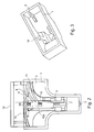
- Fig. 1a is shown in a perspective view of a lancing device according to a first embodiment of the invention.
- the lancing device comprises a base body 1, which is designed as a housing and a component 2 arranged therein, which is displaceable relative to the base body 1. From a lower end 3 of the base body 1, a needle can emerge.
- Fig. 1 b is reproduced in a perspective view of the lancing device according to the first embodiment of the invention in a disassembled state.
- the component 2 is taken out of the base body 1 and has a plastic spring 4 and a plastic spring element 4, which is arc-shaped and by means of a tension curve section 5, which on the component 2 at an angle 5a, as is apparent Fig. 2 shows, is arranged to the sliding movement of a needle connected to this.
- a needle holding member 8 is arranged, in which in turn a needle 10 with a corresponding spigot 9, which is closed by a protective cap 11 comprises.
- the needle holding member 8 can be pushed back and forth within the guide 6.
- the protective cap 11 serves as a sterile protection for the needle and is pierced during the lancing process. It consists of an elastomer.
- Fig. 2 is shown in an open and partial cross-sectional front view of the lancing device according to the first embodiment of the invention.
- the needle holding member 8 with the needle or the lancet 10 is also displaced depending on how the curve of a cam portion 13, which is preferably V-shaped and has a low point 13a is designed.
- the base body 1 has a projection 14, as shown in the perspective top view Fig. 3 is reproduced.
- This basisharmfeste projection 14 causes a deflection or a change in the direction of the tensioning cam section 5 during the upward and downward movement of the component 2, wherein both the clamping cam portion and the cam portion and the plastic spring element 4 pivotally suspended on a component 2 pivoting member 15, as it from the Fig. 4a, 4b, 4c shows, is arranged.
- This pivoting member is connected to the rest of the component 2 preferably in one piece or alternatively in two pieces.
- the component 2 is composed both of the guide recess 6 with the lower-side opening 7 and of the pivot member 15, which is preferably integrally connected at its lower side with the remaining component 2, and the plastic spring element 4 together.
- the manual actuating element is preferably integrally connected to the component 2.
- the preferably integrally cast body of the component 2 is arranged together with the pivot member 15 and then, as in Fig. 4b reproduced, the needle holding member 8 is inserted with the needle tip 9 in the guide recess 6.
- the pivoting member 15 may be connected to the rest of the component 2 by means of a film hinge, preferably based on plastic.
- the tensioning and control cam sections may be formed not only on the pivoting component 15 but also on the base body 1 and / or the needle holding element 8, wherein the respective associated cams and groove guides are designed to be complementary according to the components cooperating therewith.
- a steel spring can also be used, wherein such a steel spring can already be prestressed mounted in such a lancing device. This allows the elimination of a Vorspannweges and the tension curve section.
- Fig. 4c are clearly the tension curve section 5 and the cam portion 13 to see along which on the one hand a base body solid projection 14 and on the other hand, the needle holding member 8, which engages in the cam portion 13, which is also web or rail-like, upper and lower sides, slides.
- FIG. 5a - 5e different functional states of the lancing device according to the first embodiment of the invention are shown in a perspective view.
- Fig. 5a the lancing device is shown prior to their use, ie in unused condition. It comprises the base body 1 with the component 2 arranged therein and the underside needle exit 3 and the manual actuation element 12.
- the tension curve section 5 is slidably mounted in relation to the base body-fixed projection 14, which preferably has a triangular basic shape.
- Fig. 5b the functional state of the biasing of the plastic spring element 4 is shown.
- Nachuntenrow of the manual actuating element 12 in the base body 1 in a longitudinal sliding of the cam portion 5 takes place on the projection 14, which is biased by pivoting the pivot member 15, the plastic spring element 4 by being pressed to the left.
- This is achieved by a reinforced sheet formation of the plastic spring element 4 both in Fig. 5b as well as in Fig. 5c played.
- the needle-holding element passes through the low point 13a of the cam portion 13, but at a time when the component 2 has not yet been completely pushed into the base body 1 until it stops. This results in that although the needle tip 9 is briefly pushed downwards and then back up due to the V-shaped course of the cam portion, but not yet emerges from the lower end 3 of the base body 1.
- Fig. 5e the lancing device is shown after its use.
- the needle tip is again in the base body 1, as well as the needle holding element 8, driven in, as shown by the arrow 20.
- the component 2 remains within the base body 1 and does not move back. After such a single use, such a lancing device is not intended for further use.
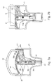
- Fig. 6a is shown in a perspective view of a lancing device according to a second embodiment of the invention.
- This lancing device in turn comprises a base body 21 together with a component 22 and an open at the bottom end 23, which may be formed like a hole.
- Fig. 6b the lancing device according to the second embodiment of the invention is shown disassembled in a perspective view.
- the component 22 in turn comprises the plastic spring element 24 and the cam portion 25. It is also the guide recess 26 with a lower end 27 for receiving the needle holding member 28 is present.
- the needle-holding element 28 in turn comprises a needle 30 with a spigot 29, which is covered by a protective cap 31.
- Fig. 7a and 7b the lancing devices according to the second and the first embodiment are shown in an open and partially cross-sectional front view for comparative purposes.
- the component 22 with the plastic spring element 24 and the cam portion 25, which in turn at an angle 25a to the direction of displacement of a manual operating element 32 and thus of the component 22 and also to the sliding movement of the needle 30 together with the needle holding element 28th is arranged.
- the cocking curve portion 25 may be slightly curved and made of inelastic or elastic material in terms of Bogenformform Kings.
- the tensioning cam portion 25 can both groove-shaped with correspondingly complementary engaging / m cams, which are / is arranged on the base body 1 /, or as a web or rail to which (r) a cam which is basis restructuringfest, along be trained.
- the tension curve section 25 in turn comprises a free end 25b.
- a cam portion 33 is again V-shaped in identical or similar shape and has a lower deepest cam portion point 33a.
- the housing-fixed projection 14 is designed such that on the one hand, the spring pressure, the linear displacement of the component 2 still supported and on the other hand, the pivotal member 15 only then the maximum lancet outlet or tip outlet achieved when the component 2 has reached its end stop within the base body. This is important for the repeatability of the piercing depth.
- the lancing device according to the first embodiment of the invention has a smaller overall size, since the pivotable part 15 has to cover a smaller angle and thus is also robust ausgestaltbar, since the plastic spring element must be less tense.
- Fig. 8a - 8c the lancing device according to the second embodiment of the invention is reproduced in a perspective view with various assembly steps.
- the component 22 has a pivotable part 35, which is hinged on the underside, preferably suspended by means of a film hinge.
- a third step the pivoting together of the pivoting part 35 and the remaining component 22 takes place such that the plastic spring element 24 can slide past on an underside of the component 22, wherein the underside 36 is formed slightly beveled for low-friction sliding past.
- the cam section 33 is again V-shaped.
- the tension curve section 25 lies below the control curve section 33.
- Fig. 9a - 9e the lancing device according to the second embodiment of the invention is shown in perspective representations during their functional sequence.
- Fig. 9a the functional state is shown before use of the lancing device.
- the component 22 is located together with the manual operating lever 32 still back slightly outside of the base body 21 and is pushed by pressurization by hand, as shown by the arrow 37, in the base body 21.
- Fig. 9b is shown in a perspective view, the insertion of the component 22 in the base body 21, as shown by the arrow 38. While this pushing is a bias of the plastic spring element 24 by pivoting the pivot member 35 to the left instead. This is done by sliding the tensioning curve section 25 along the base body-fixed projection 34, which in turn may preferably be triangular in shape.
- Fig. 9e shows the state of the entire lancing device according to the second embodiment of the invention after its use.
- Fig. 10a is shown in a perspective view of a lancing device according to a third embodiment of the invention.
- This lancing device in turn has a base body 41 with a component 42 arranged therein and a lower-side opening 43.
- Fig. 10b the lancing device according to the third embodiment is reproduced in disassembled state.
- This lancing device preferably has on its component integrally arranged a plurality of element which, the plastic spring element 44, a pivotable part 45 which is pivotally arranged on the upper side of the component and the underside has a cam portion and an actuating element 52 include.
- a guide recess 46 is disposed in member 42 for locating a needle-holding member 48 having a needle 50 disposed therein having a spigot 49 with protective cap 51 mounted thereon.
- the protective cap 51 can be turned off before actuation of the lancing device in a separate operating step and serves as a sterile protection.
- Fig. 11 the component 42 is shown again according to the lancing device according to the third embodiment.
- the component 42 comprises the pivotable part 45, which is arranged on the upper side by means of a film hinge 55 pivotally.
- the pivotable part On the underside, the pivotable part with a cam portion 53, which in turn is V-shaped in identical or similar form and having a lowest point 53 a, arranged.
- the plastic spring member 44 is pivotable relative to the remaining member 42, as shown by the double arrow 52, together with the manual operation lever 52, which is pivotally mounted at a lower point 54 by means of a living hinge on the remaining component 42.
- the pivotable manual actuating element 52 can engage with its upper end 52a into a correspondingly complementary corner edge 42a of the component 42 as soon as the manual operating element has been correspondingly pivoted into the base body.
- Fig. 12 again, the lancing device according to the third embodiment of the invention is shown in an open and partially cross-sectional front view.
- This illustration clearly shows that the plastic spring element 44 can be mounted in relation to a stop 56 of the pivotable part 45, in order to cause a release of the needle holding element upon further actuation of the manual operating element 52.
- the needle-holding element 48 is slidable by means of a groove, the control cam portion 53 on top and bottom along this section, provided that the cam portion 53, which is rail or web-like, moves from left to right.
- FIG. 13a - d again different functional states of the lancing device according to the third embodiment of the invention are shown in a perspective view.
- the lancing device is shown prior to its use.
- the manual operating element 52 which is arranged laterally, pivoted to the right, as shown by the arrow 57.
- Such a pivoting of the pivotable member 45 in particular its lower end allows the needle holding member 48 along the cam section 53, which is arranged at the lower end of the pivotable member 45, can be moved from right to left, whereupon the needle tip 49 briefly from the lower end 43 and 47 of the base body or of the component 42 exits and immediately after having overcome the lowest point 53a of the cam portion 53 is pulled into the lancing device. This results in a user-independent, faster and easier lancing process.
- Fig. 14 is shown in an open and partially cross-sectional front view in turn a lancing device according to a fourth embodiment of the invention.
- a lancing device according to a fourth embodiment of the invention.
- a plastic spring member 64 is arcuately formed on a manual operating element 72, in which case the manual operating element and the plastic spring element 64 in a nearly 90 ° angle to each other.
- the plastic spring element can be pressed along a double arrow 72b against a stop 76 of a pivotable part 65 by the manual operating lever 72 is pressed from top to bottom.
- latching mechanism is provided between the member 62 with a protrusion 62a and a springy protrusion part 65a of the pivotal member 65.
- This elastic part 65a can be triggered by a projection 72b of the manual operating element 72 in order to initiate a relaxation process after the prestressing of the plastic spring element 64 has taken place.
- the needle-holding element 68 in turn has the needle 70 with a spigot end 69.
- the pivotable element 65 is preferably arranged pivotably relative to the remaining component 62 at its lower end by means of a film hinge 75.
- the manual operating element 72 is arranged pivotably relative to the remaining component 62 by means of a film hinge 74.
- the component 62 is in turn equipped with a guide recess 66, which has a lower open end 67.
- the pivotable part 65 this time has on top a V-shaped cam portion 73, which in turn includes a lowest point 73a.
- Fig. 16a - d is the lancing device according to the fourth embodiment of the invention in a perspective partially open representation reproduced in different functional states.
- the functional state is reproduced before use. In this state, the cam portion 73 of the pivotable member 65 is still arranged with its right end against the needle holding member 68.
- Fig. 16d the lancing device is shown after its use. In this state, the pivotal member 65 has been completely pivoted from left to right, as indicated by the arrow 80.
- the pivoting elements can be designed such that they are arranged pivotably on the base body instead of by means of film hinges and are thus formed in one piece as sliding elements, which are displaceable relative to the base body, are configured.
Landscapes
- Health & Medical Sciences (AREA)
- Life Sciences & Earth Sciences (AREA)
- Heart & Thoracic Surgery (AREA)
- Surgery (AREA)
- Biophysics (AREA)
- Pathology (AREA)
- Engineering & Computer Science (AREA)
- Biomedical Technology (AREA)
- Hematology (AREA)
- Medical Informatics (AREA)
- Molecular Biology (AREA)
- Physics & Mathematics (AREA)
- Animal Behavior & Ethology (AREA)
- General Health & Medical Sciences (AREA)
- Public Health (AREA)
- Veterinary Medicine (AREA)
- Dermatology (AREA)
- Measurement Of The Respiration, Hearing Ability, Form, And Blood Characteristics Of Living Organisms (AREA)
- Infusion, Injection, And Reservoir Apparatuses (AREA)
Claims (15)
- Dispositif de piqûre destiné au prélèvement de sang lors d'examens médicaux comprenant un corps de base (1 ; 21 ; 41 ; 61), au moins une aiguille rétractable (10 ; 30 ; 50 ; 70) agencée dans celui-ci et comprenant une extrémité pointue (9 ; 29 ; 49 ; 69) avec un élément de support de l'aiguille (8 ; 28 ; 48 ; 68) entourant au moins partiellement l'aiguille (10 ; 30 ; 50 ; 70) et un élément d'actionnement manuel (12 ; 32 ; 52 ; 72) permettant de déclencher un mouvement coulissant (19) de l'aiguille (10 ; 30 ; 50 ; 70) conjointement avec l'élément de support de l'aiguille (8 ; 28 ; 48 ; 68) par rapport au corps de base (1 ; 21 ; 41 ; 61), dans au moins un composant (2 ; 22 ; 42 ; 62) étant agencé dans le corps de base (1 ; 21 ; 41 ; 61), un élément de ressort en plastique pouvant coulisser ou pivoter (4 ; 24 ; 44 ; 64) pour produire une précontrainte au moyen de l'élément d'actionnement manuel (12 ; 32 ; 52 ; 72), lequel est relié à une section de came de commande pouvant coulisser ou pivoter (13 ; 33 ; 53 ; 73) dans le corps de base (1 ; 21 ; 41 ; 61),
l'élément de support de l'aiguille (8 ; 28 ; 48 ; 68) étant relié à la section de came de commande (13 ; 33 ; 53 ; 73) et peut coulisser de façon indépendante en sens avant et arrière (18-20 ; 38-40) par éloignement de la section de came de commande coulissante ou pivotante (13 ; 33 ; 53 ; 73),
caractérisé en ce que l'élément de support de l'aiguille (8 ; 28 ; 48 ; 68) traverse la section de came de commande (13 ; 33 ; 53 ; 73) pendant un processus de détente de l'élément de ressort en plastique (4 ; 24 ; 44 ; 64). - Dispositif de piqûre selon la revendication 1,
caractérisé par
une section de came de tension (5 ; 25) agencée au niveau du composant (2 ; 22), s'étendant suivant un angle (5a ; 25a) en direction du mouvement coulissant (18-20 ; 38-40) de l'élément de support de l'aiguille (8 ; 28), qui est reliée à l'élément de ressort en plastique (4 ; 24), lequel est façonné en forme d'arc, et lors d'un mouvement coulissant (18) du composant (2 ; 22) par rapport au corps de base (1 ; 21) dans sa direction d'extension, peut être modifiée sous l'effet du glissement le long d'une saillie (14 ; 34) agencée sur le corps de base (1 ; 21) ou d'un élément agencé en forme de rainure. - Dispositif de piqûre selon la revendication 2,
caractérisé en ce que
les mouvements coulissants (18-20) de l'élément de support de l'aiguille rétractable (8) et du composant (1) présentent la même direction. - Dispositif de piqûre selon la revendication 2,
caractérisé en ce que
les mouvements coulissants (18-20) de l'élément de support de l'aiguille rétractable (8) et du composant (1) s'étendent perpendiculairement ou suivant un angle l'un par rapport à l'autre. - Dispositif de piqûre selon la revendication 2 ou 3,
caractérisé en ce que
la saillie (14 ; 34) présente une forme de base triangulaire. - Dispositif de piqûre selon l'une quelconque des revendications 2 à 4,
caractérisé en ce que
la section de came de tension (5 ; 25) présente une extrémité libre (5b, 25b), laquelle après avoir glissé devant la saillie (14; 34), peut être dirigée de façon indépendante dans sa position de départ afin de détendre l'élément de ressort en plastique (4 ; 24). - Dispositif de piqûre selon l'une quelconque des revendications 2 à 6,
caractérisé en ce que
le composant (2 ; 22) est façonné d'une seule pièce avec la section de came de commande (13 ; 33), la section de came de tension (5 ; 25) et l'élément de ressort en plastique (4 ; 24). - Dispositif de piqûre selon la revendication 1,
caractérisé en ce que
l'élément de ressort en plastique (44 ; 64) est agencé au niveau de l'élément d'actionnement manuel (52 ; 72), lequel peut pivoter (54 ; 74) par rapport au composant (42 ; 62), et peut être précontraint contre un autre élément pivotant (45 ; 65) présentant la section de came de commande (53 ; 73), lequel est logé (55 ; 75) de manière pivotante par rapport au composant (42 ; 62). - Dispositif de piqûre selon la revendication 8,
caractérisé en ce que
l'élément d'actionnement manuel (52 ; 72) présente une saillie de déclenchement (52c ; 72a) pour faire coulisser une saillie d'arrêt (48a ; 65a) de l'élément de support de l'aiguille (48) ou de l'élément pivotant (65) hors d'une position d'arrêt. - Dispositif de piqûre selon l'une quelconque des revendications précédentes,
caractérisé en ce que
l'élément d'actionnement manuel (52 ; 72) et le composant (41 ; 61) présentent un mécanisme d'encliquetage (52a ; 42a ; 62a ; 65a) pour encliqueter l'élément d'actionnement manuel (52 ; 72) dans une position pouvant être prédéterminée. - Dispositif de piqûre selon l'une quelconque des revendications 8 à 10,
caractérisé en ce que
le composant (42 ; 62) et l'élément pivotant (45 ; 65) sont façonnés d'une seule pièce. - Dispositif de piqûre selon l'une quelconque des revendications précédentes,
caractérisé en ce que
le composant (2 ; 22 ; 42 ; 62) et l'élément d'actionnement manuel (12 ; 32 ; 52 ; 72) sont façonnés d'une seule pièce. - Dispositif de piqûre selon l'une quelconque des revendications précédentes,
caractérisé en ce que
la section de came de commande (13; 33; 53; 73) s'étend selon une forme identique ou similaire à une forme en V (13a ; 33a ; 53a ; 73a). - Dispositif de piqûre selon l'une quelconque des revendications précédentes,
caractérisé en ce que
la section de came de commande (13 ; 33 ; 53 ; 73) présente dans sa longueur une entretoise, qui est entourée des deux côtés par l'élément de support de l'aiguille (8 ; 28 ; 48 ; 68) afin de glisser le long de celui-ci dans la direction d'extension de l'entretoise. - Dispositif de piqûre selon l'une quelconque des revendications 1 à 13,
caractérisé en ce que
la section de came de commande (13 ; 33 ; 53 ; 73) et/ou la section de came de tension (5 ; 25) présente dans sa longueur un évidement en forme de rainure dans lequel au moins une saillie fixée sur l'élément de support de l'aiguille s'engage afin de glisser dans celui-ci dans la direction d'extension de l'évidement.
Applications Claiming Priority (3)
| Application Number | Priority Date | Filing Date | Title |
|---|---|---|---|
| DE102007011002 | 2007-03-05 | ||
| DE102007024173A DE102007024173B4 (de) | 2007-03-05 | 2007-05-24 | Stechvorrichtung für die Blutentnahme bei medizinischen Untersuchungen |
| PCT/EP2008/052481 WO2008107379A1 (fr) | 2007-03-05 | 2008-02-29 | Dispositif de ponction permettant d'effectuer un prélèvement sanguin dans le cadre de recherches médicales |
Publications (2)
| Publication Number | Publication Date |
|---|---|
| EP2129291A1 EP2129291A1 (fr) | 2009-12-09 |
| EP2129291B1 true EP2129291B1 (fr) | 2013-08-07 |
Family
ID=39764259
Family Applications (1)
| Application Number | Title | Priority Date | Filing Date |
|---|---|---|---|
| EP08717262.3A Active EP2129291B1 (fr) | 2007-03-05 | 2008-02-29 | Dispositif de ponction permettant d'effectuer un prelevement sanguin dans le cadre de recherches medicales |
Country Status (8)
| Country | Link |
|---|---|
| US (1) | US20100087753A1 (fr) |
| EP (1) | EP2129291B1 (fr) |
| CN (1) | CN101677792B (fr) |
| BR (1) | BRPI0808534A2 (fr) |
| DE (1) | DE102007024173B4 (fr) |
| ES (1) | ES2433719T3 (fr) |
| RU (2) | RU2009132364A (fr) |
| WO (1) | WO2008107379A1 (fr) |
Family Cites Families (25)
| Publication number | Priority date | Publication date | Assignee | Title |
|---|---|---|---|---|
| US4643189A (en) * | 1985-02-19 | 1987-02-17 | W. T. Associates | Apparatus for implementing a standardized skin incision |
| SU1386776A1 (ru) * | 1986-05-29 | 1988-04-07 | Львовский политехнический институт им.Ленинского комсомола | Пневматический демпфер |
| US4715374A (en) * | 1986-11-14 | 1987-12-29 | Medicore, Inc. | Disposable automatic lancet |
| US4844095A (en) * | 1987-12-14 | 1989-07-04 | Medicore, Inc. | Automatic lancet device |
| US5324302A (en) * | 1992-10-13 | 1994-06-28 | Sherwood Medical Company | Lancet with locking cover |
| US5441513A (en) * | 1992-03-12 | 1995-08-15 | United States Surgical Corporation | Retracting tip trocar assembly |
| US5395388A (en) * | 1993-11-15 | 1995-03-07 | Schraga; Steven | Single unit lancet device |
| US5545174A (en) * | 1994-01-11 | 1996-08-13 | Sherwood Medical Company | Finger stick device |
| US5527334A (en) * | 1994-05-25 | 1996-06-18 | Ryder International Corporation | Disposable, retractable lancet |
| US5514152A (en) * | 1994-08-16 | 1996-05-07 | Specialized Health Products, Inc. | Multiple segment encapsulated medical lancing device |
| US5628765A (en) * | 1994-11-29 | 1997-05-13 | Apls Co., Ltd. | Lancet assembly |
| DE4443276A1 (de) | 1994-12-06 | 1996-06-13 | Werner Ulschmid | Wiederverwendbares Blutentnahmesystem |
| US5571132A (en) * | 1995-06-06 | 1996-11-05 | International Technidyne Corporation | Self activated finger lancet |
| DE19617000C1 (de) | 1996-04-27 | 1998-01-22 | Sarstedt Walter Geraete | Blutentnahmevorrichtung mit einem eine Kanüle aufweisenden Halter |
| US5797940A (en) * | 1997-05-30 | 1998-08-25 | International Technidyne Corporation | Adjustable skin incision device |
| US5746761A (en) * | 1997-07-03 | 1998-05-05 | Arkadiy Turchin | Disposable lancet for finger/heel stick |
| DE29718679U1 (de) | 1997-10-21 | 1997-12-18 | Wilden Engineering- und Vertriebsgesellschaft mbH, 92507 Nabburg | Lanzette für die Blutentnahme |
| US5951582A (en) * | 1998-05-22 | 1999-09-14 | Specialized Health Products, Inc. | Lancet apparatus and methods |
| CA2287757A1 (fr) * | 1999-10-29 | 2001-04-29 | Medical Plastic Devices M.P.D. Inc. | Lancette jetable |
| US7303726B2 (en) * | 2002-05-09 | 2007-12-04 | Lifescan, Inc. | Minimal procedure analyte test system |
| US7604118B2 (en) * | 2003-12-15 | 2009-10-20 | Panasonic Corporation | Puncture needle cartridge and lancet for blood collection |
| DE102004045043B4 (de) * | 2004-09-15 | 2013-09-12 | Balda Medical Gmbh & Co. Kg | Behandlungsgerät zur Blutgewinnung |
| US20060178686A1 (en) * | 2005-02-07 | 2006-08-10 | Steven Schraga | Single use lancet device |
| PL1865849T3 (pl) * | 2005-04-07 | 2017-06-30 | Becton, Dickinson And Company | Urządzenie do nakłuwania aktywowane wciskiem |
| JP5210857B2 (ja) * | 2005-04-07 | 2013-06-12 | ベクトン・ディキンソン・アンド・カンパニー | 引金式ランセット |
-
2007
- 2007-05-24 DE DE102007024173A patent/DE102007024173B4/de not_active Expired - Fee Related
-
2008
- 2008-02-29 BR BRPI0808534-0A patent/BRPI0808534A2/pt not_active IP Right Cessation
- 2008-02-29 EP EP08717262.3A patent/EP2129291B1/fr active Active
- 2008-02-29 CN CN2008800060791A patent/CN101677792B/zh active Active
- 2008-02-29 WO PCT/EP2008/052481 patent/WO2008107379A1/fr active Application Filing
- 2008-02-29 RU RU2009132364/14A patent/RU2009132364A/ru unknown
- 2008-02-29 US US12/529,896 patent/US20100087753A1/en not_active Abandoned
- 2008-02-29 RU RU2009132365/14A patent/RU2455933C2/ru not_active IP Right Cessation
- 2008-02-29 ES ES08717262T patent/ES2433719T3/es active Active
Also Published As
| Publication number | Publication date |
|---|---|
| RU2455933C2 (ru) | 2012-07-20 |
| DE102007024173A1 (de) | 2008-09-11 |
| RU2009132364A (ru) | 2011-04-10 |
| WO2008107379B1 (fr) | 2008-11-13 |
| CN101677792B (zh) | 2012-06-20 |
| DE102007024173B4 (de) | 2010-09-09 |
| ES2433719T3 (es) | 2013-12-12 |
| EP2129291A1 (fr) | 2009-12-09 |
| RU2009132365A (ru) | 2011-04-10 |
| BRPI0808534A2 (pt) | 2014-08-26 |
| CN101677792A (zh) | 2010-03-24 |
| WO2008107379A1 (fr) | 2008-09-12 |
| US20100087753A1 (en) | 2010-04-08 |
Similar Documents
| Publication | Publication Date | Title |
|---|---|---|
| EP2606823B1 (fr) | Système de prélèvement du sang | |
| DE2657053C3 (de) | Vorrichtung aus einer Akupunkturnadel und einem Gerät zum Einstechen derselben | |
| DE60005421T2 (de) | Schmerzärmere Lanzette | |
| EP1631337B1 (fr) | Dispositif d'insertion pour equipement de perfusion | |
| EP1371329B1 (fr) | Système de prélèvement du sang | |
| DE69017387T2 (de) | Verbesserungen für Blutentnahmegeräte. | |
| DE60109358T2 (de) | Lanzettenvorrichtung | |
| DE60317997T2 (de) | Lanzette | |
| DE60218170T2 (de) | Durchstechvorrichtung | |
| EP2213229B1 (fr) | Système de prise de sang | |
| EP1808128A1 (fr) | Dispositif auxiliaire de piqûre avec protection contre réutilisation | |
| EP1970084A1 (fr) | Dispositif d'insertion pour une tête d'insertion, en particulier pour un ensemble d'infusion | |
| EP2413798B1 (fr) | Matériel de piqûre à dispositif d'éjection de lancette | |
| DE19909602A1 (de) | Gerät zur Entnahme von Blut für Diagnosezwecke | |
| EP1970083A1 (fr) | Dispositif d'insertion pour une tête d'insertion, en particulier pour un ensemble d'infusion | |
| EP2314206B1 (fr) | Système de piqûre pour l'extraction d'un liquide corporel | |
| DE102007024181B4 (de) | Stechvorrichtung für die Blutentnahme mit einer Schenkelfeder | |
| EP2382921A1 (fr) | Aide à la plantation dotée d'un déclenchement automatique | |
| EP2129291B1 (fr) | Dispositif de ponction permettant d'effectuer un prelevement sanguin dans le cadre de recherches medicales | |
| DE102011014200B4 (de) | Stechhilfe mit seitlich angebrachtem Betätigungselement | |
| DE102011017275B4 (de) | Stechhilfe für die Durchführung einer Blutentnahme | |
| DE102011015590B4 (de) | Stechhilfe mit mindestens einer Lanzette zur Gewinnung von Körperflüssigkeiten | |
| DE102007024183B4 (de) | Stechvorrichtung mit Verdrehfeder | |
| DE102013021058A1 (de) | Vorrichtung zur Applizierung eines Nadelarrays auf biologischem Gewebe | |
| DE2416877A1 (de) | Pinzette |
Legal Events
| Date | Code | Title | Description |
|---|---|---|---|
| PUAI | Public reference made under article 153(3) epc to a published international application that has entered the european phase |
Free format text: ORIGINAL CODE: 0009012 |
|
| 17P | Request for examination filed |
Effective date: 20090916 |
|
| AK | Designated contracting states |
Kind code of ref document: A1 Designated state(s): AT BE BG CH CY CZ DE DK EE ES FI FR GB GR HR HU IE IS IT LI LT LU LV MC MT NL NO PL PT RO SE SI SK TR |
|
| DAX | Request for extension of the european patent (deleted) | ||
| RAP1 | Party data changed (applicant data changed or rights of an application transferred) |
Owner name: GERRESHEIMER REGENSBURG GMBH |
|
| 17Q | First examination report despatched |
Effective date: 20110406 |
|
| GRAP | Despatch of communication of intention to grant a patent |
Free format text: ORIGINAL CODE: EPIDOSNIGR1 |
|
| RAP1 | Party data changed (applicant data changed or rights of an application transferred) |
Owner name: GERRESHEIMER REGENSBURG GMBH |
|
| GRAS | Grant fee paid |
Free format text: ORIGINAL CODE: EPIDOSNIGR3 |
|
| GRAA | (expected) grant |
Free format text: ORIGINAL CODE: 0009210 |
|
| AK | Designated contracting states |
Kind code of ref document: B1 Designated state(s): AT BE BG CH CY CZ DE DK EE ES FI FR GB GR HR HU IE IS IT LI LT LU LV MC MT NL NO PL PT RO SE SI SK TR |
|
| REG | Reference to a national code |
Ref country code: GB Ref legal event code: FG4D Free format text: NOT ENGLISH |
|
| REG | Reference to a national code |
Ref country code: AT Ref legal event code: REF Ref document number: 625363 Country of ref document: AT Kind code of ref document: T Effective date: 20130815 Ref country code: CH Ref legal event code: EP |
|
| REG | Reference to a national code |
Ref country code: IE Ref legal event code: FG4D Free format text: LANGUAGE OF EP DOCUMENT: GERMAN |
|
| REG | Reference to a national code |
Ref country code: DE Ref legal event code: R096 Ref document number: 502008010439 Country of ref document: DE Effective date: 20131002 |
|
| REG | Reference to a national code |
Ref country code: ES Ref legal event code: FG2A Ref document number: 2433719 Country of ref document: ES Kind code of ref document: T3 Effective date: 20131212 |
|
| REG | Reference to a national code |
Ref country code: NL Ref legal event code: VDEP Effective date: 20130807 |
|
| REG | Reference to a national code |
Ref country code: LT Ref legal event code: MG4D |
|
| PG25 | Lapsed in a contracting state [announced via postgrant information from national office to epo] |
Ref country code: HR Free format text: LAPSE BECAUSE OF FAILURE TO SUBMIT A TRANSLATION OF THE DESCRIPTION OR TO PAY THE FEE WITHIN THE PRESCRIBED TIME-LIMIT Effective date: 20130807 Ref country code: IS Free format text: LAPSE BECAUSE OF FAILURE TO SUBMIT A TRANSLATION OF THE DESCRIPTION OR TO PAY THE FEE WITHIN THE PRESCRIBED TIME-LIMIT Effective date: 20131207 Ref country code: LT Free format text: LAPSE BECAUSE OF FAILURE TO SUBMIT A TRANSLATION OF THE DESCRIPTION OR TO PAY THE FEE WITHIN THE PRESCRIBED TIME-LIMIT Effective date: 20130807 Ref country code: NO Free format text: LAPSE BECAUSE OF FAILURE TO SUBMIT A TRANSLATION OF THE DESCRIPTION OR TO PAY THE FEE WITHIN THE PRESCRIBED TIME-LIMIT Effective date: 20131107 Ref country code: PT Free format text: LAPSE BECAUSE OF FAILURE TO SUBMIT A TRANSLATION OF THE DESCRIPTION OR TO PAY THE FEE WITHIN THE PRESCRIBED TIME-LIMIT Effective date: 20131209 Ref country code: CY Free format text: LAPSE BECAUSE OF FAILURE TO SUBMIT A TRANSLATION OF THE DESCRIPTION OR TO PAY THE FEE WITHIN THE PRESCRIBED TIME-LIMIT Effective date: 20130814 Ref country code: SE Free format text: LAPSE BECAUSE OF FAILURE TO SUBMIT A TRANSLATION OF THE DESCRIPTION OR TO PAY THE FEE WITHIN THE PRESCRIBED TIME-LIMIT Effective date: 20130807 |
|
| PG25 | Lapsed in a contracting state [announced via postgrant information from national office to epo] |
Ref country code: PL Free format text: LAPSE BECAUSE OF FAILURE TO SUBMIT A TRANSLATION OF THE DESCRIPTION OR TO PAY THE FEE WITHIN THE PRESCRIBED TIME-LIMIT Effective date: 20130807 Ref country code: SI Free format text: LAPSE BECAUSE OF FAILURE TO SUBMIT A TRANSLATION OF THE DESCRIPTION OR TO PAY THE FEE WITHIN THE PRESCRIBED TIME-LIMIT Effective date: 20130807 Ref country code: LV Free format text: LAPSE BECAUSE OF FAILURE TO SUBMIT A TRANSLATION OF THE DESCRIPTION OR TO PAY THE FEE WITHIN THE PRESCRIBED TIME-LIMIT Effective date: 20130807 Ref country code: NL Free format text: LAPSE BECAUSE OF FAILURE TO SUBMIT A TRANSLATION OF THE DESCRIPTION OR TO PAY THE FEE WITHIN THE PRESCRIBED TIME-LIMIT Effective date: 20130807 Ref country code: FI Free format text: LAPSE BECAUSE OF FAILURE TO SUBMIT A TRANSLATION OF THE DESCRIPTION OR TO PAY THE FEE WITHIN THE PRESCRIBED TIME-LIMIT Effective date: 20130807 Ref country code: GR Free format text: LAPSE BECAUSE OF FAILURE TO SUBMIT A TRANSLATION OF THE DESCRIPTION OR TO PAY THE FEE WITHIN THE PRESCRIBED TIME-LIMIT Effective date: 20131108 |
|
| PG25 | Lapsed in a contracting state [announced via postgrant information from national office to epo] |
Ref country code: CY Free format text: LAPSE BECAUSE OF FAILURE TO SUBMIT A TRANSLATION OF THE DESCRIPTION OR TO PAY THE FEE WITHIN THE PRESCRIBED TIME-LIMIT Effective date: 20130807 |
|
| PG25 | Lapsed in a contracting state [announced via postgrant information from national office to epo] |
Ref country code: SK Free format text: LAPSE BECAUSE OF FAILURE TO SUBMIT A TRANSLATION OF THE DESCRIPTION OR TO PAY THE FEE WITHIN THE PRESCRIBED TIME-LIMIT Effective date: 20130807 Ref country code: DK Free format text: LAPSE BECAUSE OF FAILURE TO SUBMIT A TRANSLATION OF THE DESCRIPTION OR TO PAY THE FEE WITHIN THE PRESCRIBED TIME-LIMIT Effective date: 20130807 Ref country code: CZ Free format text: LAPSE BECAUSE OF FAILURE TO SUBMIT A TRANSLATION OF THE DESCRIPTION OR TO PAY THE FEE WITHIN THE PRESCRIBED TIME-LIMIT Effective date: 20130807 Ref country code: RO Free format text: LAPSE BECAUSE OF FAILURE TO SUBMIT A TRANSLATION OF THE DESCRIPTION OR TO PAY THE FEE WITHIN THE PRESCRIBED TIME-LIMIT Effective date: 20130807 Ref country code: EE Free format text: LAPSE BECAUSE OF FAILURE TO SUBMIT A TRANSLATION OF THE DESCRIPTION OR TO PAY THE FEE WITHIN THE PRESCRIBED TIME-LIMIT Effective date: 20130807 |
|
| PLBE | No opposition filed within time limit |
Free format text: ORIGINAL CODE: 0009261 |
|
| STAA | Information on the status of an ep patent application or granted ep patent |
Free format text: STATUS: NO OPPOSITION FILED WITHIN TIME LIMIT |
|
| 26N | No opposition filed |
Effective date: 20140508 |
|
| REG | Reference to a national code |
Ref country code: DE Ref legal event code: R097 Ref document number: 502008010439 Country of ref document: DE Effective date: 20140508 |
|
| BERE | Be: lapsed |
Owner name: GERRESHEIMER REGENSBURG G.M.B.H. Effective date: 20140228 |
|
| PG25 | Lapsed in a contracting state [announced via postgrant information from national office to epo] |
Ref country code: LU Free format text: LAPSE BECAUSE OF FAILURE TO SUBMIT A TRANSLATION OF THE DESCRIPTION OR TO PAY THE FEE WITHIN THE PRESCRIBED TIME-LIMIT Effective date: 20140228 |
|
| REG | Reference to a national code |
Ref country code: CH Ref legal event code: PL |
|
| PG25 | Lapsed in a contracting state [announced via postgrant information from national office to epo] |
Ref country code: CH Free format text: LAPSE BECAUSE OF NON-PAYMENT OF DUE FEES Effective date: 20140228 Ref country code: LI Free format text: LAPSE BECAUSE OF NON-PAYMENT OF DUE FEES Effective date: 20140228 |
|
| REG | Reference to a national code |
Ref country code: IE Ref legal event code: MM4A |
|
| PG25 | Lapsed in a contracting state [announced via postgrant information from national office to epo] |
Ref country code: BE Free format text: LAPSE BECAUSE OF NON-PAYMENT OF DUE FEES Effective date: 20140228 Ref country code: IE Free format text: LAPSE BECAUSE OF NON-PAYMENT OF DUE FEES Effective date: 20140228 |
|
| REG | Reference to a national code |
Ref country code: AT Ref legal event code: MM01 Ref document number: 625363 Country of ref document: AT Kind code of ref document: T Effective date: 20140228 |
|
| PG25 | Lapsed in a contracting state [announced via postgrant information from national office to epo] |
Ref country code: AT Free format text: LAPSE BECAUSE OF NON-PAYMENT OF DUE FEES Effective date: 20140228 |
|
| REG | Reference to a national code |
Ref country code: ES Ref legal event code: FD2A Effective date: 20151002 |
|
| PG25 | Lapsed in a contracting state [announced via postgrant information from national office to epo] |
Ref country code: ES Free format text: LAPSE BECAUSE OF NON-PAYMENT OF DUE FEES Effective date: 20140301 |
|
| REG | Reference to a national code |
Ref country code: FR Ref legal event code: PLFP Year of fee payment: 9 |
|
| PG25 | Lapsed in a contracting state [announced via postgrant information from national office to epo] |
Ref country code: MT Free format text: LAPSE BECAUSE OF FAILURE TO SUBMIT A TRANSLATION OF THE DESCRIPTION OR TO PAY THE FEE WITHIN THE PRESCRIBED TIME-LIMIT Effective date: 20130807 |
|
| PG25 | Lapsed in a contracting state [announced via postgrant information from national office to epo] |
Ref country code: MC Free format text: LAPSE BECAUSE OF FAILURE TO SUBMIT A TRANSLATION OF THE DESCRIPTION OR TO PAY THE FEE WITHIN THE PRESCRIBED TIME-LIMIT Effective date: 20130807 Ref country code: BG Free format text: LAPSE BECAUSE OF FAILURE TO SUBMIT A TRANSLATION OF THE DESCRIPTION OR TO PAY THE FEE WITHIN THE PRESCRIBED TIME-LIMIT Effective date: 20130807 |
|
| PG25 | Lapsed in a contracting state [announced via postgrant information from national office to epo] |
Ref country code: IT Free format text: LAPSE BECAUSE OF NON-PAYMENT OF DUE FEES Effective date: 20140228 |
|
| PG25 | Lapsed in a contracting state [announced via postgrant information from national office to epo] |
Ref country code: TR Free format text: LAPSE BECAUSE OF FAILURE TO SUBMIT A TRANSLATION OF THE DESCRIPTION OR TO PAY THE FEE WITHIN THE PRESCRIBED TIME-LIMIT Effective date: 20130807 Ref country code: HU Free format text: LAPSE BECAUSE OF FAILURE TO SUBMIT A TRANSLATION OF THE DESCRIPTION OR TO PAY THE FEE WITHIN THE PRESCRIBED TIME-LIMIT; INVALID AB INITIO Effective date: 20080229 |
|
| REG | Reference to a national code |
Ref country code: FR Ref legal event code: PLFP Year of fee payment: 10 |
|
| REG | Reference to a national code |
Ref country code: FR Ref legal event code: PLFP Year of fee payment: 11 |
|
| P01 | Opt-out of the competence of the unified patent court (upc) registered |
Effective date: 20230523 |
|
| PGFP | Annual fee paid to national office [announced via postgrant information from national office to epo] |
Ref country code: DE Payment date: 20240216 Year of fee payment: 17 Ref country code: GB Payment date: 20240222 Year of fee payment: 17 |
|
| PGFP | Annual fee paid to national office [announced via postgrant information from national office to epo] |
Ref country code: FR Payment date: 20240222 Year of fee payment: 17 |