EP2606823B1 - Système de prélèvement du sang - Google Patents
Système de prélèvement du sang Download PDFInfo
- Publication number
- EP2606823B1 EP2606823B1 EP13000864.2A EP13000864A EP2606823B1 EP 2606823 B1 EP2606823 B1 EP 2606823B1 EP 13000864 A EP13000864 A EP 13000864A EP 2606823 B1 EP2606823 B1 EP 2606823B1
- Authority
- EP
- European Patent Office
- Prior art keywords
- lancet
- drive
- control
- motion
- blood withdrawal
- Prior art date
- Legal status (The legal status is an assumption and is not a legal conclusion. Google has not performed a legal analysis and makes no representation as to the accuracy of the status listed.)
- Expired - Lifetime
Links
- 238000010241 blood sampling Methods 0.000 title 1
- 230000033001 locomotion Effects 0.000 claims description 57
- 230000007246 mechanism Effects 0.000 claims description 43
- 239000008280 blood Substances 0.000 claims description 41
- 210000004369 blood Anatomy 0.000 claims description 41
- 230000005540 biological transmission Effects 0.000 claims description 18
- 230000008878 coupling Effects 0.000 claims description 17
- 238000010168 coupling process Methods 0.000 claims description 17
- 238000005859 coupling reaction Methods 0.000 claims description 17
- 238000006073 displacement reaction Methods 0.000 claims description 2
- 230000005764 inhibitory process Effects 0.000 claims description 2
- 230000002040 relaxant effect Effects 0.000 claims 1
- 230000001360 synchronised effect Effects 0.000 claims 1
- 230000006870 function Effects 0.000 description 9
- 210000002105 tongue Anatomy 0.000 description 7
- 230000000694 effects Effects 0.000 description 5
- 230000009471 action Effects 0.000 description 4
- 238000010276 construction Methods 0.000 description 4
- 230000004913 activation Effects 0.000 description 3
- 238000013461 design Methods 0.000 description 3
- 238000011161 development Methods 0.000 description 2
- 230000005484 gravity Effects 0.000 description 2
- NOESYZHRGYRDHS-UHFFFAOYSA-N insulin Chemical compound N1C(=O)C(NC(=O)C(CCC(N)=O)NC(=O)C(CCC(O)=O)NC(=O)C(C(C)C)NC(=O)C(NC(=O)CN)C(C)CC)CSSCC(C(NC(CO)C(=O)NC(CC(C)C)C(=O)NC(CC=2C=CC(O)=CC=2)C(=O)NC(CCC(N)=O)C(=O)NC(CC(C)C)C(=O)NC(CCC(O)=O)C(=O)NC(CC(N)=O)C(=O)NC(CC=2C=CC(O)=CC=2)C(=O)NC(CSSCC(NC(=O)C(C(C)C)NC(=O)C(CC(C)C)NC(=O)C(CC=2C=CC(O)=CC=2)NC(=O)C(CC(C)C)NC(=O)C(C)NC(=O)C(CCC(O)=O)NC(=O)C(C(C)C)NC(=O)C(CC(C)C)NC(=O)C(CC=2NC=NC=2)NC(=O)C(CO)NC(=O)CNC2=O)C(=O)NCC(=O)NC(CCC(O)=O)C(=O)NC(CCCNC(N)=N)C(=O)NCC(=O)NC(CC=3C=CC=CC=3)C(=O)NC(CC=3C=CC=CC=3)C(=O)NC(CC=3C=CC(O)=CC=3)C(=O)NC(C(C)O)C(=O)N3C(CCC3)C(=O)NC(CCCCN)C(=O)NC(C)C(O)=O)C(=O)NC(CC(N)=O)C(O)=O)=O)NC(=O)C(C(C)CC)NC(=O)C(CO)NC(=O)C(C(C)O)NC(=O)C1CSSCC2NC(=O)C(CC(C)C)NC(=O)C(NC(=O)C(CCC(N)=O)NC(=O)C(CC(N)=O)NC(=O)C(NC(=O)C(N)CC=1C=CC=CC=1)C(C)C)CC1=CN=CN1 NOESYZHRGYRDHS-UHFFFAOYSA-N 0.000 description 2
- 238000002560 therapeutic procedure Methods 0.000 description 2
- 201000004569 Blindness Diseases 0.000 description 1
- 240000003517 Elaeocarpus dentatus Species 0.000 description 1
- 206010016352 Feeling of relaxation Diseases 0.000 description 1
- 241001295925 Gegenes Species 0.000 description 1
- 102000004877 Insulin Human genes 0.000 description 1
- 108090001061 Insulin Proteins 0.000 description 1
- 208000017442 Retinal disease Diseases 0.000 description 1
- 206010038923 Retinopathy Diseases 0.000 description 1
- 230000004888 barrier function Effects 0.000 description 1
- 230000008859 change Effects 0.000 description 1
- 230000006835 compression Effects 0.000 description 1
- 238000007906 compression Methods 0.000 description 1
- 230000008094 contradictory effect Effects 0.000 description 1
- 230000001276 controlling effect Effects 0.000 description 1
- 230000000881 depressing effect Effects 0.000 description 1
- 206010012601 diabetes mellitus Diseases 0.000 description 1
- 230000009977 dual effect Effects 0.000 description 1
- 210000000624 ear auricle Anatomy 0.000 description 1
- 210000003811 finger Anatomy 0.000 description 1
- 230000037406 food intake Effects 0.000 description 1
- 235000012631 food intake Nutrition 0.000 description 1
- 230000001771 impaired effect Effects 0.000 description 1
- 230000006872 improvement Effects 0.000 description 1
- 239000007924 injection Substances 0.000 description 1
- 238000002347 injection Methods 0.000 description 1
- 238000003780 insertion Methods 0.000 description 1
- 230000037431 insertion Effects 0.000 description 1
- 229940125396 insulin Drugs 0.000 description 1
- 239000002184 metal Substances 0.000 description 1
- 238000012544 monitoring process Methods 0.000 description 1
- 230000008058 pain sensation Effects 0.000 description 1
- 230000000737 periodic effect Effects 0.000 description 1
- 230000037081 physical activity Effects 0.000 description 1
- 238000011160 research Methods 0.000 description 1
- 210000003813 thumb Anatomy 0.000 description 1
- 238000013519 translation Methods 0.000 description 1
Images


Classifications
-
- A—HUMAN NECESSITIES
- A61—MEDICAL OR VETERINARY SCIENCE; HYGIENE
- A61B—DIAGNOSIS; SURGERY; IDENTIFICATION
- A61B5/00—Measuring for diagnostic purposes; Identification of persons
- A61B5/15—Devices for taking samples of blood
- A61B5/150007—Details
- A61B5/150206—Construction or design features not otherwise provided for; manufacturing or production; packages; sterilisation of piercing element, piercing device or sampling device
-
- A—HUMAN NECESSITIES
- A61—MEDICAL OR VETERINARY SCIENCE; HYGIENE
- A61B—DIAGNOSIS; SURGERY; IDENTIFICATION
- A61B5/00—Measuring for diagnostic purposes; Identification of persons
- A61B5/15—Devices for taking samples of blood
- A61B5/150007—Details
- A61B5/150015—Source of blood
- A61B5/150022—Source of blood for capillary blood or interstitial fluid
-
- A—HUMAN NECESSITIES
- A61—MEDICAL OR VETERINARY SCIENCE; HYGIENE
- A61B—DIAGNOSIS; SURGERY; IDENTIFICATION
- A61B5/00—Measuring for diagnostic purposes; Identification of persons
- A61B5/15—Devices for taking samples of blood
- A61B5/150007—Details
- A61B5/150374—Details of piercing elements or protective means for preventing accidental injuries by such piercing elements
- A61B5/150381—Design of piercing elements
- A61B5/150412—Pointed piercing elements, e.g. needles, lancets for piercing the skin
-
- A—HUMAN NECESSITIES
- A61—MEDICAL OR VETERINARY SCIENCE; HYGIENE
- A61B—DIAGNOSIS; SURGERY; IDENTIFICATION
- A61B5/00—Measuring for diagnostic purposes; Identification of persons
- A61B5/15—Devices for taking samples of blood
- A61B5/151—Devices specially adapted for taking samples of capillary blood, e.g. by lancets, needles or blades
- A61B5/15101—Details
- A61B5/15103—Piercing procedure
- A61B5/15107—Piercing being assisted by a triggering mechanism
- A61B5/15113—Manually triggered, i.e. the triggering requires a deliberate action by the user such as pressing a drive button
-
- A—HUMAN NECESSITIES
- A61—MEDICAL OR VETERINARY SCIENCE; HYGIENE
- A61B—DIAGNOSIS; SURGERY; IDENTIFICATION
- A61B5/00—Measuring for diagnostic purposes; Identification of persons
- A61B5/15—Devices for taking samples of blood
- A61B5/151—Devices specially adapted for taking samples of capillary blood, e.g. by lancets, needles or blades
- A61B5/15101—Details
- A61B5/15115—Driving means for propelling the piercing element to pierce the skin, e.g. comprising mechanisms based on shape memory alloys, magnetism, solenoids, piezoelectric effect, biased elements, resilient elements, vacuum or compressed fluids
- A61B5/15117—Driving means for propelling the piercing element to pierce the skin, e.g. comprising mechanisms based on shape memory alloys, magnetism, solenoids, piezoelectric effect, biased elements, resilient elements, vacuum or compressed fluids comprising biased elements, resilient elements or a spring, e.g. a helical spring, leaf spring, or elastic strap
-
- A—HUMAN NECESSITIES
- A61—MEDICAL OR VETERINARY SCIENCE; HYGIENE
- A61B—DIAGNOSIS; SURGERY; IDENTIFICATION
- A61B5/00—Measuring for diagnostic purposes; Identification of persons
- A61B5/15—Devices for taking samples of blood
- A61B5/151—Devices specially adapted for taking samples of capillary blood, e.g. by lancets, needles or blades
- A61B5/15101—Details
- A61B5/15126—Means for controlling the lancing movement, e.g. 2D- or 3D-shaped elements, tooth-shaped elements or sliding guides
- A61B5/15128—Means for controlling the lancing movement, e.g. 2D- or 3D-shaped elements, tooth-shaped elements or sliding guides comprising 2D- or 3D-shaped elements, e.g. cams, curved guide rails or threads
-
- A—HUMAN NECESSITIES
- A61—MEDICAL OR VETERINARY SCIENCE; HYGIENE
- A61B—DIAGNOSIS; SURGERY; IDENTIFICATION
- A61B5/00—Measuring for diagnostic purposes; Identification of persons
- A61B5/15—Devices for taking samples of blood
- A61B5/151—Devices specially adapted for taking samples of capillary blood, e.g. by lancets, needles or blades
- A61B5/15101—Details
- A61B5/15126—Means for controlling the lancing movement, e.g. 2D- or 3D-shaped elements, tooth-shaped elements or sliding guides
- A61B5/1513—Means for controlling the lancing movement, e.g. 2D- or 3D-shaped elements, tooth-shaped elements or sliding guides comprising linear sliding guides
-
- A—HUMAN NECESSITIES
- A61—MEDICAL OR VETERINARY SCIENCE; HYGIENE
- A61B—DIAGNOSIS; SURGERY; IDENTIFICATION
- A61B5/00—Measuring for diagnostic purposes; Identification of persons
- A61B5/15—Devices for taking samples of blood
- A61B5/151—Devices specially adapted for taking samples of capillary blood, e.g. by lancets, needles or blades
- A61B5/15101—Details
- A61B5/15126—Means for controlling the lancing movement, e.g. 2D- or 3D-shaped elements, tooth-shaped elements or sliding guides
- A61B5/15132—Means for controlling the lancing movement, e.g. 2D- or 3D-shaped elements, tooth-shaped elements or sliding guides comprising tooth-shaped elements, e.g. toothed wheel or rack and pinion
-
- A—HUMAN NECESSITIES
- A61—MEDICAL OR VETERINARY SCIENCE; HYGIENE
- A61B—DIAGNOSIS; SURGERY; IDENTIFICATION
- A61B5/00—Measuring for diagnostic purposes; Identification of persons
- A61B5/15—Devices for taking samples of blood
- A61B5/151—Devices specially adapted for taking samples of capillary blood, e.g. by lancets, needles or blades
- A61B5/15186—Devices loaded with a single lancet, i.e. a single lancet with or without a casing is loaded into a reusable drive device and then discarded after use; drive devices reloadable for multiple use
- A61B5/15188—Constructional features of reusable driving devices
- A61B5/1519—Constructional features of reusable driving devices comprising driving means, e.g. a spring, for propelling the piercing unit
-
- A—HUMAN NECESSITIES
- A61—MEDICAL OR VETERINARY SCIENCE; HYGIENE
- A61B—DIAGNOSIS; SURGERY; IDENTIFICATION
- A61B5/00—Measuring for diagnostic purposes; Identification of persons
- A61B5/15—Devices for taking samples of blood
- A61B5/151—Devices specially adapted for taking samples of capillary blood, e.g. by lancets, needles or blades
- A61B5/15186—Devices loaded with a single lancet, i.e. a single lancet with or without a casing is loaded into a reusable drive device and then discarded after use; drive devices reloadable for multiple use
- A61B5/15188—Constructional features of reusable driving devices
- A61B5/15192—Constructional features of reusable driving devices comprising driving means, e.g. a spring, for retracting the lancet unit into the driving device housing
- A61B5/15194—Constructional features of reusable driving devices comprising driving means, e.g. a spring, for retracting the lancet unit into the driving device housing fully automatically retracted, i.e. the retraction does not require a deliberate action by the user, e.g. by terminating the contact with the patient's skin
Definitions
- the invention relates to a blood collection system for taking blood for diagnostic purposes.
- the puncture phase represented the kinematic reversal of the tension phase.
- the drive was tensioned simply by pushing the lancet back to the starting position after the puncture had been made, in which the spring was stretched.
- the two coupling mechanisms usually consist of at least partially different components. In any case, the movements in both phases are different (not just a kinematic reversal of the other phase).
- the invention relates to a blood collection system with the features of claim 1.
- a puncturing device in which the front end of the housing in the piercing direction is formed by a cap, which is removable for removing used lancets.
- the term "ejection mechanism” is commonly used to refer to a combination of mechanical elements which, in general, make it possible to remove the lancet from the puncturing device by moving an actuating button without touching it. "Ejecting” in this sense does not mean that the lancet is accelerated when removed from the device. Rather, it is generally considered advantageous if only a lancet holder present in the lancing device is opened by the ejection mechanism, so that the lancet falls out by gravity.
- the Auswerfmechanismus is inoperable, as long as the cap is placed at the front end of the housing of the puncturing device.
- a lancet drive which includes a drive rotor driven by the drive spring and rotatable about an axis is preferred, wherein in the drive phase of the lancet drive the drive rotor, driven by the drive spring, performs a rotational movement which is converted into the puncturing movement by means of the output-side coupling mechanism.
- a rotor drive is used, for example, in the lancet systems described in the above cited documents (2), (3) and (4).
- the present invention is used in conjunction with a special rotor drive, which is not vorpubliziert in the EP 1 384 438 A1 (as well as the equivalent patent applications US 10 / 445,606 and JP 14978012003 ) is described.
- the actuating element of the tensioning device with a web control, which as members of the path control, a control track part and a.
- Control cam includes, coupled, wherein the control cam during at least a portion of the clamping phase makes a relative movement with respect to the control track portion, in which it moves away the control track of the control track portion and thereby at least a portion of the movement of the Lanzettenabtriebs is controlled.
- a path control mechanism is provided.
- This additional path control mechanism is coupled to the actuator of the tensioner and controls at least portions of the movement of the lancet drive. It has two parts, which are referred to as members of the path control, namely a control track part and a control cam.
- the control effect is based on that during the movement of the lancet drive the control track portion and the control cam cooperate with the lancet drive in such a way that a relative movement of the control cam takes place with respect to the control track, wherein the control cam follows the control track, i. it "leaves” and thereby a control function of the lancet drive in the clamping phase and / or in the puncture phase is effected.
- the required guidance of the control cam along the control track can be achieved by different design measures.
- the control track can be formed by a groove in the control track part whose width is matched to the dimensions of the control cam, that it is precisely guided in the control track.
- the controlling effect can also be achieved in that the control track is designed as a sliding surface against which the control cam is pressed under spring action.
- one of the links is coupled to the operating element of the tensioning device in the sense that it is synchronously moved together with it.
- the coupling may be rigid or movable, wherein in the case of a movable coupling conventional coupling elements, such as levers, for connecting the actuating element of the clamping device with the ("input side") member of the path control, with which it is coupled, can be used.
- this input-side member is the control track portion, while the output-side member of the path control (which is coupled to the lancet drive so as to transmit the control effect of the path control thereon) is preferably formed by the control cam.
- the relative movement of the control cam with respect to the control track part can be realized by different combinations of movements of the two members of the path control.
- the control track part can be moved on a partial section of the relative movement, while the control cam is stationary relative to the housing of the puncturing device.
- the departure of the control track may be based on a movement of the control cam at stationary control track part.
- both members of the path control can be moved simultaneously. Details depend on the individual case.
- the control track part is at least during at least part of the desired control operation translationally moved, while the movement of the control cam preferably at least partially extends on a circular path.
- the actuating element of the clamping device is usually realized as a clamping knob, which protrudes from the rear (the puncture opening opposite) end of an elongated housing and is normally operated by pressing with the thumb.
- the invention is also suitable for use with other operating elements of the clamping device, for example a slider movable along the housing wall or a pull-movable actuating element which can be formed, for example, by the rear housing part.
- a tension knob without loss of generality.
- the blood collection system 1 shown in the figures consists of a lancing device 2 and lancets 3.
- the holder and guide a lancet 3 in the lancing device 2 is in FIG. 7 shown.
- a lancet holder 4 engages with retaining tongues 4a as the lancet body 5 called the rear part of the lancet. From the lancet body 5, a lancet tip 6 protrudes forward.
- the lancet holder 4 is guided by means of a housing part serving as a guide (not shown) and thus indirectly provides the required guidance of the lancet on a predetermined puncture path (here along the main axis A of the puncturing device 2). In this case, therefore, the lancet is guided indirectly by means of the lancet holder 4.
- the invention is also applicable to puncturing devices in which the lancet is "directly guided", ie located directly in a part of the housing (for example a magazine containing a plurality of lancets) which forms the necessary guide during the puncturing motion. Also, this can provide more information EP 1 384 438 A1 be removed.
- a lancet drive 9 which serves to move a lancet at high speed in the puncture direction (arrow 10) until its tip exits from an outlet opening 11, while the lancing device 2 with an outlet opening 11 surrounding Contact surface 12 is pressed against an unillustrated body part. As a result, a wound for taking blood is generated in the body part.
- the housing 8 of the puncturing device has an elongated shape. The end at which the outlet opening 11 is located is referred to here as the front end, the opposite end as the rear end. The front end of the housing 8 is formed by a removable cap 7.
- FIGS. 1 to 6 illustrate the design features of the lancet drive 12, which are required for the power transmission during the clamping phase and during the propulsion phase.
- a tensioning knob 14 the force exerted on a tensioning knob 14 is transmitted to a drive spring 16 (here integrated into a drive module 15) by means of a tensioning device, designated in its entirety by 13, in order to tension it.
- the drive spring 16 relaxes and thereby drives a drive rotor 17, whose rotary motion is in turn converted into the translatory puncturing movement of the lancet holder 4.
- This power transmission is in the present invention with the EP 1 384 438 A1 match.
- Components of the drive module 15 are the drive rotor 17 and a tensioning element 19, which are rotatable about a common axis C which is perpendicular to the puncture direction 10 and to the longitudinal axis A of the puncturing device 2.
- a rack 21 is part of the power transmission part 20 and drives a with the clamping element 19 coaxial pinion 22 at.
- the pinion 22 is connected to the clamping element 19 via a freewheel 23 such that both parts during the clamping movement (movement of the power transmission member 20 in the puncture direction) coupled together, however, in the return of the power transmission member 20 and the clamping knob 14 under the Effect, a return spring 14a are decoupled.
- the freewheel 23 is realized by means of two elastic tongues 24 which are connected to the pinion 22.
- the tongues 24 are located in a recess 25, facing away from the drive rotor 17, of the tensioning element 19 with stops 27 on which the ends of the tongues 24 in the coupling direction of rotation (in FIG. 2 in the clockwise direction), while in the reverse direction, the pinion 22 can rotate freely relative to the clamping element 19.
- the drive spring 16 is tensioned, which is designed as a spiral spring and is mounted in a drive rotor 17 facing recess 28 of the clamping element 19.
- the output-side coupling mechanism 30, by which the force of the spring 16 is transmitted in the propulsion phase to the lancet 3, includes a control cam 31, which is formed by a circumferential groove 32.
- the control cam 31 has the shape of a circle C eccentric to the axis C in the case shown. It is driven off during the rotation of the drive rotor 17 by a control pin 33 which is part of the lancet holder 4.
- the lancet holder 4 has elastic arms 35 and a stop element 36 whose shape is matched to the corresponding shape of the lancet body 5, that the lancets 3 is held in a precisely reproducible longitudinal position in the lancet holder 4.
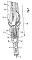
- FIGS. 7 to 9 show the main design features of the web control 40 and the ejection mechanism 41, which, based on the drive rotor 17, are on the side of the piercing device 2, the in FIG. 1 recognizable drive side 42 opposite and is referred to as the control side 43.
- the members of the path control 40 are a control track portion 45 and a control cam 46, which is formed in the illustrated embodiment as fixed to the drive rotor 17 pin.
- the drive spring 16 exerts a (depending on their respective state of tension different strong, but always rectified) torque on the drive rotor 17 and thus on the control cam 46 (in the figures in the clockwise direction).
- the drive rotor 17 is seated on the control track part 45 in such a way that the control cam 46 is located in a control track 47 of the control track part 45 (in FIG. 8 is such a control position of the control cam 46 indicated by dashed lines).
- a relative movement of the control cam 46 with respect to the control track part 45 results on the one hand, when the Steuerbahntell 45 is moved parallel to the longitudinal axis A of the piercing device 2, and on the other hand by the movement of the control cam 46 in a circular path about the axis C.
- the translation movement of the control track part 45 results from it in that it is coupled to the tensioning knob 14.
- control track portion 45 and the power transmission member 20 is integrally formed with the rack 21 and bent approximately U-shaped, so that in the installed position, the two legs of the U on the two sides of the drive module 15, namely the power transmission part 20 the drive side 42 and the control track part 45 on the control side 43.
- the rear end of the interconnected Components 20, 45 is attached to the clamping knob 14 such that both parts are moved uniformly translationally upon actuation of the clamping knob 14.
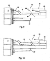
- FIGS. 8 to 10 are the central parts of the generally designated 41 ejection mechanism to recognize, which consists in the illustrated embodiment of the clamping knob 14, the control track portion 45 and an unlocking element 61.
- These components are each mounted translationally displaceable in the puncturing direction 10 (and thus in the direction of the axis A of the device) and form a force transmission chain, which is symbolized by the arrow 70 and by which the movement of an actuating button of the lancet ejection mechanism is transmitted to the lancet holder 4 in such a way. that the lancet 3 is released and can fall out of the holder 4 by gravity.
- the actuating button of the lancet ejection mechanism is at the same time the actuating element of the clamping device, ie the tensioning knob 14. This is true not necessary, but especially preferred. Overall, a triple function of a single operating knob (clamping, release, ejection) is thus possible.
- the release of the lancet is achieved in the illustrated embodiment in that on the unlocking element 61 formed sliding tongues 62 between the elastic tongues 4a of the lancet holder 4 and an obliquely outwardly extending abutment 63 of the lancet holder 4 are pressed. As a result, the holding tongues 4a are pressed apart and release the lancet 3.
- the lancet ejection mechanism 41 is passivated, i. the operation of the clamping knob 14 does not lead to the ejection of the lancet.
- FIG. 9 is the unlocking element in the passive position, in which the power transmission chain 70 is interrupted between the tensioning knob and the lancet:
- the cap 7 includes an in FIG. 9 dashed shown abutment 64 which presses against the front end of a trained on the activation element 61 actuating piece 65 as long as the cap is placed.
- a pressure piece 68 of the unlocking element against a device-fixed in FIG. 9 only schematically indicated oblique surface 69 pressed.
- the activation element is in the in FIG. 9 shown horizontal position held. A displacement of the front end of the control track part 45 according to the arrow 66 is not transmitted to the release element 61, because both parts do not come into engagement with each other.
Landscapes
- Health & Medical Sciences (AREA)
- Life Sciences & Earth Sciences (AREA)
- Engineering & Computer Science (AREA)
- Heart & Thoracic Surgery (AREA)
- Molecular Biology (AREA)
- Pathology (AREA)
- Physics & Mathematics (AREA)
- Biomedical Technology (AREA)
- Hematology (AREA)
- Medical Informatics (AREA)
- Biophysics (AREA)
- Surgery (AREA)
- Animal Behavior & Ethology (AREA)
- General Health & Medical Sciences (AREA)
- Public Health (AREA)
- Veterinary Medicine (AREA)
- Manufacturing & Machinery (AREA)
- Dermatology (AREA)
- Measurement Of The Respiration, Hearing Ability, Form, And Blood Characteristics Of Living Organisms (AREA)
Claims (14)
- Système de prélèvement de sang pour prélever du sang à des fins de diagnostic, comprenant
un boîtier (8), dans lequel une lancette (3) est déplaçable le long d'un trajet de piqûre prédéterminé, et
un entraînement de lancette (9) avec un ressort d'entraînement (16) et un dispositif tendeur (13),- le dispositif tendeur (13) incluant un élément d'actionnement (14) qui, au moyen d'un mécanisme de couplage (29) côté entrée, est couplé au ressort d'entraînement (16) de façon à tendre ce dernier durant une phase de tension du mouvement de l'entraînement de lancette (9) lorsque l'élément d'actionnement (14) est déplacé, et- le ressort d'entraînement (16), au moyen d'un mécanisme de couplage (30) côté sortie, étant couplé à la lancette (3) de façon à déplacer ladite lancette (3) durant une phase de propulsion du mouvement de l'entraînement de lancette (9) pendant le mouvement de détente du ressort d'entraînement (16) à grande vitesse sur le trajet de piqûre prédéterminé dans le sens de la piqûre (10) afin d'effectuer un mouvement de piqûre,l'extrémité avant du boîtier (8) dans le sens de la piqûre étant formée par un capuchon (7), lequel est amovible pour retirer les lancettes utilisées,
caractérisé en ce que
il inclut un mécanisme d'éjection de lancette (41) doté d'un élément de libération (61) lequel est logé dans le boîtier (8) avec possibilité de réglage entre une position passive et une position active, dans la position active de l'élément de libération (61) le mécanisme d'éjection de lancette (41) étant activé, de sorte que par actionnement d'un bouton d'actionnement du mécanisme d'éjection de lancette (41) une lancette (3) utilisée est retirée du boîtier (8), et dans la position passive de l'élément de libération (61) le mécanisme d'éjection de lancette (41) est passivé, de sorte que l'actionnement du bouton d'actionnement n'entraîne pas l'éjection d'une lancette,
le capuchon (7), lorsqu'il est posé, coopère avec l'élément de libération (61) de sorte que celui-ci se trouve en position passive, et
l'élément de libération (61) passe en position active en ôtant le capuchon (7). - Système de prélèvement de sang selon la revendication 1, caractérisé en ce que
l'élément de libération (61) fait partie d'une chaîne de transmission de force (70) nécessaire pour l'éjection d'une lancette (3), entre le bouton d'actionnement et la lancette,
l'élément de libération (61) peut coulisser dans la même direction que le bouton d'actionnement, et
la chaîne de transmission de force (70) est interrompue en position passive de l'élément de libération (61). - Système de prélèvement de sang selon l'une des revendications 1 ou 2, caractérisé en ce que l'élément d'actionnement (14) du dispositif tendeur (13) de l'entraînement de lancette (9) est en même temps le bouton d'actionnement du mécanisme d'éjection de lancette (41).
- Système de prélèvement de sang selon l'une des revendications précédentes, caractérisé en ce que
l'élément d'actionnement (14) du dispositif tendeur (13) est couplé à une commande de trajectoire (40) qui comprend comme organes de la commande de trajectoire (40) un élément de commande de trajectoire (45) et une came de commande (46), ladite came de commande (46) effectuant pendant au moins une partie de la phase de tension un mouvement relatif par rapport à l'élément de commande de trajectoire (45), mouvement lors duquel elle suit la trajectoire de commande (47) de l'élément de commande de trajectoire (45), permettant ainsi de commander au moins une partie du mouvement de l'entraînement de lancette (9). - Système de prélèvement de sang selon la revendication 4, caractérisé en ce que l'élément de commande de trajectoire (45) est l'organe côté entrée de la commande de trajectoire (40) tourné vers l'élément d'actionnement (14) du dispositif tendeur (13).
- Système de prélèvement de sang selon l'une des revendications 4 ou 5, caractérisé en ce que le boîtier (8) a une forme allongée et l'élément de commande de trajectoire (45) ou la came de commande (46) est guidé(e) et se déplace dans le boîtier (8) parallèlement à l'axe longitudinal (A) de celui-ci.
- Système de prélèvement de sang selon la revendication 6, caractérisé en ce que l'élément d'actionnement (14) du dispositif tendeur (13) est un bouton tendeur qui déborde de l'extrémité arrière du boîtier (8) opposée à l'orifice de sortie (11) de la pointe de lancette.
- Système de prélèvement de sang selon l'une des revendications précédentes, caractérisé en ce que la trajectoire de commande de l'élément de commande de trajectoire (45) inclut un tronçon à voie unique (53) qui est conçu de telle manière que la came de commande (46), lorsqu'elle est rentrée dans le tronçon à voie unique (53), ne peut en ressortir que dans un sens du tronçon à voie unique (53), de sorte qu'un mouvement relatif de la came de commande par rapport à l'élément de commande de trajectoire (45) au-delà du tronçon à voie unique (53) n'est possible que dans un sens de la trajectoire de commande.
- Système de prélèvement de sang selon l'une des revendications précédentes, caractérisé en ce que l'entraînement de lancette inclut un rotor d'entraînement (17) entraîné par le ressort d'entraînement (16) et mobile autour d'un axe (C), et durant la phase de propulsion du mouvement de l'entraînement de lancette (9), le mouvement de rotation du rotor d'entraînement (17) est transformé en mouvement de piqûre par le mécanisme de couplage (30) côté sortie.
- Système de prélèvement de sang selon la revendication 9, caractérisé en ce que l'un des organes (45, 46) de la commande de trajectoire (40) est couplé au rotor d'entraînement (17) de telle sorte qu'il tourne en synchronisme avec ce dernier.
- Système de prélèvement de sang selon la revendication 10, caractérisé en ce que l'organe de la commande de trajectoire (40) couplé au rotor d'entraînement (17) est la came de commande (46).
- Système de prélèvement de sang selon l'une des revendications 9 à 11, caractérisé en ce que le mécanisme de couplage (30) côté sortie inclut un évidement (32) formant une came de commande (31) et dans lequel s'engage un tenon de commande (33), ledit tenon de commande (33), pendant le mouvement de rotation du rotor d'entraînement (17) se produisant durant la phase de propulsion, suivant la came de commande (31) formée par l'évidement (32), permettant ainsi de déterminer au moins une partie du mouvement de la lancette (3) durant la phase de propulsion, l'excursion maximale de la lancette dans le sens de la piqûre (10) étant déterminée par un point d'inversion bas de la came de commande.
- Système de prélèvement de sang selon l'une des revendications 9 à 12, caractérisé en ce que l'extrémité du ressort d'entraînement (16) opposée au rotor d'entraînement (17) s'appuie contre un élément tendeur (19) mobile en rotation,
l'élément tendeur (19), de manière à tendre le ressort d'entraînement (16) lorsque la rotation du rotor d'entraînement (17) est bloquée, peut tourner dans le même sens de rotation dans lequel tourne le rotor d'entraînement (17) durant la phase de propulsion, et
l'élément tendeur (19), durant la phase de propulsion, est bloqué contre une rotation inverse de sorte que le rotor d'entraînement, après libération du blocage, effectue un mouvement de rotation qui est transformé en mouvement de piqûre de la lancette au moyen du mécanisme de couplage (30) côté sortie. - Système de prélèvement de sang selon la revendication 13, caractérisé en ce que l'élément tendeur (19) mobile en rotation et le rotor d'entraînement (17) sont des composants, mobiles autour d'un axe commun (C), d'un module d'entraînement (15).
Applications Claiming Priority (2)
| Application Number | Priority Date | Filing Date | Title |
|---|---|---|---|
| DE10336933A DE10336933B4 (de) | 2003-08-07 | 2003-08-07 | Blutentnahmesystem |
| EP04017054.0A EP1504718B1 (fr) | 2003-08-07 | 2004-07-20 | Système de prélèvement du sang |
Related Parent Applications (2)
| Application Number | Title | Priority Date | Filing Date |
|---|---|---|---|
| EP04017054.0A Division EP1504718B1 (fr) | 2003-08-07 | 2004-07-20 | Système de prélèvement du sang |
| EP04017054.0 Division | 2004-07-20 |
Publications (2)
| Publication Number | Publication Date |
|---|---|
| EP2606823A1 EP2606823A1 (fr) | 2013-06-26 |
| EP2606823B1 true EP2606823B1 (fr) | 2014-12-24 |
Family
ID=33547189
Family Applications (2)
| Application Number | Title | Priority Date | Filing Date |
|---|---|---|---|
| EP04017054.0A Expired - Lifetime EP1504718B1 (fr) | 2003-08-07 | 2004-07-20 | Système de prélèvement du sang |
| EP13000864.2A Expired - Lifetime EP2606823B1 (fr) | 2003-08-07 | 2004-07-20 | Système de prélèvement du sang |
Family Applications Before (1)
| Application Number | Title | Priority Date | Filing Date |
|---|---|---|---|
| EP04017054.0A Expired - Lifetime EP1504718B1 (fr) | 2003-08-07 | 2004-07-20 | Système de prélèvement du sang |
Country Status (7)
| Country | Link |
|---|---|
| US (2) | US7273484B2 (fr) |
| EP (2) | EP1504718B1 (fr) |
| JP (2) | JP3939319B2 (fr) |
| CA (2) | CA2475705C (fr) |
| DE (1) | DE10336933B4 (fr) |
| ES (1) | ES2429437T3 (fr) |
| PL (1) | PL1504718T3 (fr) |
Families Citing this family (143)
| Publication number | Priority date | Publication date | Assignee | Title |
|---|---|---|---|---|
| US6036924A (en) | 1997-12-04 | 2000-03-14 | Hewlett-Packard Company | Cassette of lancet cartridges for sampling blood |
| US6391005B1 (en) | 1998-03-30 | 2002-05-21 | Agilent Technologies, Inc. | Apparatus and method for penetration with shaft having a sensor for sensing penetration depth |
| US8641644B2 (en) | 2000-11-21 | 2014-02-04 | Sanofi-Aventis Deutschland Gmbh | Blood testing apparatus having a rotatable cartridge with multiple lancing elements and testing means |
| US7344507B2 (en) | 2002-04-19 | 2008-03-18 | Pelikan Technologies, Inc. | Method and apparatus for lancet actuation |
| AU2002312521A1 (en) | 2001-06-12 | 2002-12-23 | Pelikan Technologies, Inc. | Blood sampling apparatus and method |
| US7041068B2 (en) | 2001-06-12 | 2006-05-09 | Pelikan Technologies, Inc. | Sampling module device and method |
| AU2002315177A1 (en) | 2001-06-12 | 2002-12-23 | Pelikan Technologies, Inc. | Self optimizing lancing device with adaptation means to temporal variations in cutaneous properties |
| US9795747B2 (en) | 2010-06-02 | 2017-10-24 | Sanofi-Aventis Deutschland Gmbh | Methods and apparatus for lancet actuation |
| US9226699B2 (en) | 2002-04-19 | 2016-01-05 | Sanofi-Aventis Deutschland Gmbh | Body fluid sampling module with a continuous compression tissue interface surface |
| JP4149911B2 (ja) | 2001-06-12 | 2008-09-17 | ペリカン テクノロジーズ インコーポレイテッド | 電気式ランセットアクチュエータ |
| WO2002100254A2 (fr) | 2001-06-12 | 2002-12-19 | Pelikan Technologies, Inc. | Procede et appareil pour un dispositif de lancement de lancette integre sur une cartouche de prelevement de sang |
| US8337419B2 (en) | 2002-04-19 | 2012-12-25 | Sanofi-Aventis Deutschland Gmbh | Tissue penetration device |
| US7981056B2 (en) | 2002-04-19 | 2011-07-19 | Pelikan Technologies, Inc. | Methods and apparatus for lancet actuation |
| WO2002100461A2 (fr) | 2001-06-12 | 2002-12-19 | Pelikan Technologies, Inc. | Dispositif et procede permettant d'ameliorer le rendement du prelevement de sang capillaire au bout du doigt |
| US9427532B2 (en) | 2001-06-12 | 2016-08-30 | Sanofi-Aventis Deutschland Gmbh | Tissue penetration device |
| US7331931B2 (en) | 2002-04-19 | 2008-02-19 | Pelikan Technologies, Inc. | Method and apparatus for penetrating tissue |
| US7909778B2 (en) | 2002-04-19 | 2011-03-22 | Pelikan Technologies, Inc. | Method and apparatus for penetrating tissue |
| US7976476B2 (en) | 2002-04-19 | 2011-07-12 | Pelikan Technologies, Inc. | Device and method for variable speed lancet |
| US7547287B2 (en) | 2002-04-19 | 2009-06-16 | Pelikan Technologies, Inc. | Method and apparatus for penetrating tissue |
| US9314194B2 (en) | 2002-04-19 | 2016-04-19 | Sanofi-Aventis Deutschland Gmbh | Tissue penetration device |
| US7229458B2 (en) | 2002-04-19 | 2007-06-12 | Pelikan Technologies, Inc. | Method and apparatus for penetrating tissue |
| US8579831B2 (en) | 2002-04-19 | 2013-11-12 | Sanofi-Aventis Deutschland Gmbh | Method and apparatus for penetrating tissue |
| US8267870B2 (en) | 2002-04-19 | 2012-09-18 | Sanofi-Aventis Deutschland Gmbh | Method and apparatus for body fluid sampling with hybrid actuation |
| US7491178B2 (en) | 2002-04-19 | 2009-02-17 | Pelikan Technologies, Inc. | Method and apparatus for penetrating tissue |
| US8360992B2 (en) | 2002-04-19 | 2013-01-29 | Sanofi-Aventis Deutschland Gmbh | Method and apparatus for penetrating tissue |
| US7674232B2 (en) | 2002-04-19 | 2010-03-09 | Pelikan Technologies, Inc. | Method and apparatus for penetrating tissue |
| US7232451B2 (en) | 2002-04-19 | 2007-06-19 | Pelikan Technologies, Inc. | Method and apparatus for penetrating tissue |
| US7901362B2 (en) | 2002-04-19 | 2011-03-08 | Pelikan Technologies, Inc. | Method and apparatus for penetrating tissue |
| US7371247B2 (en) | 2002-04-19 | 2008-05-13 | Pelikan Technologies, Inc | Method and apparatus for penetrating tissue |
| US7297122B2 (en) | 2002-04-19 | 2007-11-20 | Pelikan Technologies, Inc. | Method and apparatus for penetrating tissue |
| US7717863B2 (en) | 2002-04-19 | 2010-05-18 | Pelikan Technologies, Inc. | Method and apparatus for penetrating tissue |
| US9248267B2 (en) | 2002-04-19 | 2016-02-02 | Sanofi-Aventis Deustchland Gmbh | Tissue penetration device |
| US7892183B2 (en) | 2002-04-19 | 2011-02-22 | Pelikan Technologies, Inc. | Method and apparatus for body fluid sampling and analyte sensing |
| US9795334B2 (en) | 2002-04-19 | 2017-10-24 | Sanofi-Aventis Deutschland Gmbh | Method and apparatus for penetrating tissue |
| US8702624B2 (en) | 2006-09-29 | 2014-04-22 | Sanofi-Aventis Deutschland Gmbh | Analyte measurement device with a single shot actuator |
| US7648468B2 (en) | 2002-04-19 | 2010-01-19 | Pelikon Technologies, Inc. | Method and apparatus for penetrating tissue |
| US8784335B2 (en) | 2002-04-19 | 2014-07-22 | Sanofi-Aventis Deutschland Gmbh | Body fluid sampling device with a capacitive sensor |
| US8372016B2 (en) | 2002-04-19 | 2013-02-12 | Sanofi-Aventis Deutschland Gmbh | Method and apparatus for body fluid sampling and analyte sensing |
| US7291117B2 (en) | 2002-04-19 | 2007-11-06 | Pelikan Technologies, Inc. | Method and apparatus for penetrating tissue |
| US8221334B2 (en) | 2002-04-19 | 2012-07-17 | Sanofi-Aventis Deutschland Gmbh | Method and apparatus for penetrating tissue |
| US7713214B2 (en) | 2002-04-19 | 2010-05-11 | Pelikan Technologies, Inc. | Method and apparatus for a multi-use body fluid sampling device with optical analyte sensing |
| DE10223558A1 (de) * | 2002-05-28 | 2003-12-11 | Roche Diagnostics Gmbh | Blutentnahmesystem |
| US7381184B2 (en) | 2002-11-05 | 2008-06-03 | Abbott Diabetes Care Inc. | Sensor inserter assembly |
| US8574895B2 (en) | 2002-12-30 | 2013-11-05 | Sanofi-Aventis Deutschland Gmbh | Method and apparatus using optical techniques to measure analyte levels |
| EP1628567B1 (fr) | 2003-05-30 | 2010-08-04 | Pelikan Technologies Inc. | Procede et appareil pour injection de fluide |
| EP1633235B1 (fr) | 2003-06-06 | 2014-05-21 | Sanofi-Aventis Deutschland GmbH | Appareil d'echantillonnage de fluides anatomiques et d'examen de l'analysat |
| WO2006001797A1 (fr) | 2004-06-14 | 2006-01-05 | Pelikan Technologies, Inc. | Element penetrant peu douloureux |
| US7510564B2 (en) * | 2003-06-27 | 2009-03-31 | Abbott Diabetes Care Inc. | Lancing device |
| US20190357827A1 (en) | 2003-08-01 | 2019-11-28 | Dexcom, Inc. | Analyte sensor |
| DE10336933B4 (de) * | 2003-08-07 | 2007-04-26 | Roche Diagnostics Gmbh | Blutentnahmesystem |
| US8282576B2 (en) | 2003-09-29 | 2012-10-09 | Sanofi-Aventis Deutschland Gmbh | Method and apparatus for an improved sample capture device |
| EP1680014A4 (fr) | 2003-10-14 | 2009-01-21 | Pelikan Technologies Inc | Procede et appareil fournissant une interface-utilisateur variable |
| USD914881S1 (en) | 2003-11-05 | 2021-03-30 | Abbott Diabetes Care Inc. | Analyte sensor electronic mount |
| DE10360786B4 (de) * | 2003-12-23 | 2005-12-22 | Roche Diagnostics Gmbh | Analysehandgerät |
| EP1706026B1 (fr) | 2003-12-31 | 2017-03-01 | Sanofi-Aventis Deutschland GmbH | Procédé et appareil permettant d'améliorer le flux fluidique et le prélèvement d'échantillons |
| US7822454B1 (en) | 2005-01-03 | 2010-10-26 | Pelikan Technologies, Inc. | Fluid sampling device with improved analyte detecting member configuration |
| WO2009048462A1 (fr) | 2007-10-09 | 2009-04-16 | Dexcom, Inc. | Système d'administration d'insuline intégré avec un capteur de glucose en continu |
| US8133246B1 (en) * | 2004-04-16 | 2012-03-13 | Caribbean Medical Brokers, Inc. | Safety lancet assembly |
| US9101302B2 (en) * | 2004-05-03 | 2015-08-11 | Abbott Diabetes Care Inc. | Analyte test device |
| EP1751546A2 (fr) | 2004-05-20 | 2007-02-14 | Albatros Technologies GmbH & Co. KG | Hydrogel imprimable pour biocapteurs |
| EP1765194A4 (fr) | 2004-06-03 | 2010-09-29 | Pelikan Technologies Inc | Procede et appareil pour la fabrication d'un dispositif d'echantillonnage de liquides |
| US9775553B2 (en) | 2004-06-03 | 2017-10-03 | Sanofi-Aventis Deutschland Gmbh | Method and apparatus for a fluid sampling device |
| US7512432B2 (en) | 2004-07-27 | 2009-03-31 | Abbott Laboratories | Sensor array |
| DE102004037270B4 (de) | 2004-07-31 | 2008-01-31 | Roche Diagnostics Gmbh | Blutentnahmesystem zur Entnahme von Blut für Diagnosezwecke |
| US7731657B2 (en) | 2005-08-30 | 2010-06-08 | Abbott Diabetes Care Inc. | Analyte sensor introducer and methods of use |
| US8333714B2 (en) | 2006-09-10 | 2012-12-18 | Abbott Diabetes Care Inc. | Method and system for providing an integrated analyte sensor insertion device and data processing unit |
| US8545403B2 (en) | 2005-12-28 | 2013-10-01 | Abbott Diabetes Care Inc. | Medical device insertion |
| US8512243B2 (en) | 2005-09-30 | 2013-08-20 | Abbott Diabetes Care Inc. | Integrated introducer and transmitter assembly and methods of use |
| US9572534B2 (en) | 2010-06-29 | 2017-02-21 | Abbott Diabetes Care Inc. | Devices, systems and methods for on-skin or on-body mounting of medical devices |
| US8571624B2 (en) | 2004-12-29 | 2013-10-29 | Abbott Diabetes Care Inc. | Method and apparatus for mounting a data transmission device in a communication system |
| US9351669B2 (en) | 2009-09-30 | 2016-05-31 | Abbott Diabetes Care Inc. | Interconnect for on-body analyte monitoring device |
| US9398882B2 (en) | 2005-09-30 | 2016-07-26 | Abbott Diabetes Care Inc. | Method and apparatus for providing analyte sensor and data processing device |
| US9788771B2 (en) | 2006-10-23 | 2017-10-17 | Abbott Diabetes Care Inc. | Variable speed sensor insertion devices and methods of use |
| US7883464B2 (en) | 2005-09-30 | 2011-02-08 | Abbott Diabetes Care Inc. | Integrated transmitter unit and sensor introducer mechanism and methods of use |
| US20110060196A1 (en) * | 2009-08-31 | 2011-03-10 | Abbott Diabetes Care Inc. | Flexible Mounting Unit and Cover for a Medical Device |
| US10226207B2 (en) | 2004-12-29 | 2019-03-12 | Abbott Diabetes Care Inc. | Sensor inserter having introducer |
| US7697967B2 (en) | 2005-12-28 | 2010-04-13 | Abbott Diabetes Care Inc. | Method and apparatus for providing analyte sensor insertion |
| US8613703B2 (en) | 2007-05-31 | 2013-12-24 | Abbott Diabetes Care Inc. | Insertion devices and methods |
| US20090105569A1 (en) | 2006-04-28 | 2009-04-23 | Abbott Diabetes Care, Inc. | Introducer Assembly and Methods of Use |
| US9743862B2 (en) | 2011-03-31 | 2017-08-29 | Abbott Diabetes Care Inc. | Systems and methods for transcutaneously implanting medical devices |
| US8029441B2 (en) | 2006-02-28 | 2011-10-04 | Abbott Diabetes Care Inc. | Analyte sensor transmitter unit configuration for a data monitoring and management system |
| US9259175B2 (en) | 2006-10-23 | 2016-02-16 | Abbott Diabetes Care, Inc. | Flexible patch for fluid delivery and monitoring body analytes |
| US8652831B2 (en) | 2004-12-30 | 2014-02-18 | Sanofi-Aventis Deutschland Gmbh | Method and apparatus for analyte measurement test time |
| DE102005004498B4 (de) * | 2005-02-01 | 2009-07-09 | Roche Diagnostics Gmbh | Antrieb für medizinische Geräte und Verwendung für einen solchen Antrieb |
| WO2006096630A1 (fr) | 2005-03-04 | 2006-09-14 | Bayer Healthcare Llc | Mecanisme de declenchement d'une lancette |
| WO2006096537A1 (fr) * | 2005-03-04 | 2006-09-14 | Bayer Healthcare Llc | Mecanisme d'actionnement de lancette |
| CN101163448A (zh) | 2005-03-04 | 2008-04-16 | 拜尔保健有限公司 | 刺血针释放机构 |
| WO2006107914A2 (fr) * | 2005-04-04 | 2006-10-12 | Facet Technologies, Llc | Dispositif de lancette a profil etroit |
| US9521968B2 (en) | 2005-09-30 | 2016-12-20 | Abbott Diabetes Care Inc. | Analyte sensor retention mechanism and methods of use |
| US11298058B2 (en) | 2005-12-28 | 2022-04-12 | Abbott Diabetes Care Inc. | Method and apparatus for providing analyte sensor insertion |
| US7955348B2 (en) * | 2006-06-15 | 2011-06-07 | Abbott Diabetes Care Inc. | Lancing devices and methods |
| EP1884191B1 (fr) | 2006-08-02 | 2009-09-23 | Roche Diagnostics GmbH | Système a piquer la peau |
| PL1897493T3 (pl) | 2006-09-04 | 2011-04-29 | Hoffmann La Roche | Zestaw nakłuwający do pobierania płynu ustrojowego |
| WO2008111936A1 (fr) * | 2007-03-12 | 2008-09-18 | Bayer Healthcare Llc | Mécanisme d'éjection de lancette |
| EP1990001A1 (fr) | 2007-05-10 | 2008-11-12 | Roche Diagnostics GmbH | Système de connexion et bande de transport à lancette |
| US9179867B2 (en) * | 2007-06-19 | 2015-11-10 | Stat Medical Devices, Inc. | Lancet device with depth adjustment and lancet removal system and method |
| GB0715798D0 (en) | 2007-08-14 | 2007-09-19 | Owen Mumford Ltd | Lancing devices |
| GB2451840B (en) * | 2007-08-14 | 2012-01-18 | Owen Mumford Ltd | Lancing devices |
| EP2039293A1 (fr) * | 2007-09-19 | 2009-03-25 | F. Hoffman-la Roche AG | Entraînement de combinaison pour un système d'obtention d'échantillons pour obtenir un échantillon liquide |
| US20090099437A1 (en) * | 2007-10-11 | 2009-04-16 | Vadim Yuzhakov | Lancing Depth Adjustment Via Moving Cap |
| EP2050393B1 (fr) * | 2007-10-19 | 2011-04-13 | Bionime Corporation | Dispositif de lancement |
| US8579866B2 (en) | 2008-01-11 | 2013-11-12 | Ucb Pharma, S.A. | Systems and methods for administering medication |
| WO2009126900A1 (fr) | 2008-04-11 | 2009-10-15 | Pelikan Technologies, Inc. | Procédé et appareil pour dispositif de détection d’analyte |
| WO2009148431A1 (fr) * | 2008-06-05 | 2009-12-10 | Bayer Healthcare Llc | Dispositif autopiqueur |
| US8828038B2 (en) * | 2008-06-05 | 2014-09-09 | Bayer Healthcare Llc | Lancing device |
| DE102008037082B4 (de) * | 2008-06-06 | 2012-05-24 | Gerresheimer Regensburg Gmbh | Stechvorrichtung für eine Blutprobenentnahme |
| USD641078S1 (en) | 2008-12-29 | 2011-07-05 | Ucb Pharma, S.A. | Medical syringe with needle tip cap |
| DK2326371T3 (da) | 2008-07-18 | 2019-11-18 | Ucb Biopharma Sprl | Systemer til indgift af medicin til patienter med rheumatoid arthritis |
| US8652159B2 (en) * | 2008-07-29 | 2014-02-18 | Facet Technologies, Llc | Lancet |
| US8029526B2 (en) * | 2008-08-14 | 2011-10-04 | Abbott Diabetes Care Inc. | Cocking mechanism for lancing device |
| US8568434B2 (en) * | 2008-10-14 | 2013-10-29 | Bionime Corporation | Lancing device |
| WO2010080585A1 (fr) * | 2008-12-18 | 2010-07-15 | Facet Technologies, Llc | Autopiqueur et lancette |
| US9375169B2 (en) | 2009-01-30 | 2016-06-28 | Sanofi-Aventis Deutschland Gmbh | Cam drive for managing disposable penetrating member actions with a single motor and motor and control system |
| US20100198034A1 (en) | 2009-02-03 | 2010-08-05 | Abbott Diabetes Care Inc. | Compact On-Body Physiological Monitoring Devices and Methods Thereof |
| DE102009025443B4 (de) * | 2009-04-03 | 2012-06-06 | Gerresheimer Regensburg Gmbh | Blutlanzettenvorrichtung mit Stechtiefeneinstellung |
| CN102497813B (zh) * | 2009-07-14 | 2018-01-12 | 霍夫曼-拉罗奇有限公司 | 具有摩擦离合器的分析测试仪器 |
| USD660958S1 (en) | 2009-07-20 | 2012-05-29 | Ucb Pharma, S.A. | Device for administering medication |
| CN105686807B (zh) | 2009-08-31 | 2019-11-15 | 雅培糖尿病护理公司 | 医疗设备 |
| US20110106126A1 (en) * | 2009-08-31 | 2011-05-05 | Michael Love | Inserter device including rotor subassembly |
| EP2490591B1 (fr) * | 2009-10-22 | 2013-12-25 | Facet Technologies, LLC | Autopiqueur à ensemble de guidage amélioré |
| USD924406S1 (en) | 2010-02-01 | 2021-07-06 | Abbott Diabetes Care Inc. | Analyte sensor inserter |
| BRPI1105769A2 (pt) | 2010-03-24 | 2016-05-03 | Abbott Diabetes Care Inc | insersores de dispositivo médico e processos de inserção e uso de dispositivos médicos. |
| USD634426S1 (en) | 2010-04-08 | 2011-03-15 | Facet Technologies, Llc | Lancing device |
| US8965476B2 (en) | 2010-04-16 | 2015-02-24 | Sanofi-Aventis Deutschland Gmbh | Tissue penetration device |
| EP2382921A1 (fr) * | 2010-04-30 | 2011-11-02 | Roche Diagnostics GmbH | Aide à la plantation dotée d'un déclenchement automatique |
| US11064921B2 (en) | 2010-06-29 | 2021-07-20 | Abbott Diabetes Care Inc. | Devices, systems and methods for on-skin or on-body mounting of medical devices |
| DK4056105T3 (da) | 2011-12-11 | 2024-01-02 | Abbott Diabetes Care Inc | Analytsensorindretninger |
| CA2857503C (fr) | 2011-12-15 | 2020-10-27 | Facet Technologies, Llc | Mecanisme de loquet destine a empecher l'oscillation d'une lancette dans un autopiqueur |
| CA2869342A1 (fr) | 2012-04-11 | 2013-10-17 | Facet Technologies, Llc | Dispositif autopiqueur avec reglage de profondeur de pivot mobile |
| US10456069B2 (en) | 2012-04-12 | 2019-10-29 | Facet Technologies, Llc | Lancing device with side activated charge and eject mechanisms |
| US9149221B2 (en) * | 2012-09-13 | 2015-10-06 | Facet Technologies, Llc | Push-to-charge mechanism for lancing device |
| US10070811B2 (en) | 2014-06-26 | 2018-09-11 | Stat Medical Devices, Inc. | Lancing device with depth adjustment and lancet removal system and method |
| US10213139B2 (en) | 2015-05-14 | 2019-02-26 | Abbott Diabetes Care Inc. | Systems, devices, and methods for assembling an applicator and sensor control device |
| EP3294134B1 (fr) | 2015-05-14 | 2020-07-08 | Abbott Diabetes Care Inc. | Système d'insertion de dispositif medical compact et procédé associé |
| US11375932B2 (en) | 2015-12-30 | 2022-07-05 | Dexcom, Inc. | Transcutaneous analyte sensor systems and methods |
| US11071478B2 (en) | 2017-01-23 | 2021-07-27 | Abbott Diabetes Care Inc. | Systems, devices and methods for analyte sensor insertion |
| ES2963745T3 (es) | 2017-06-23 | 2024-04-01 | Dexcom Inc | Sensores de analito transcutáneo, aplicadores de los mismos y cono de aguja que comprenden función anti-giro |
| US11331022B2 (en) | 2017-10-24 | 2022-05-17 | Dexcom, Inc. | Pre-connected analyte sensors |
| CN209606445U (zh) | 2017-10-24 | 2019-11-08 | 德克斯康公司 | 预连接分析物传感器 |
| USD926325S1 (en) | 2018-06-22 | 2021-07-27 | Dexcom, Inc. | Wearable medical monitoring device |
| KR102090538B1 (ko) * | 2019-03-14 | 2020-03-19 | (주)로아메드 | 무통 채혈침 전용 누름 장전식 채혈기 |
| USD1002852S1 (en) | 2019-06-06 | 2023-10-24 | Abbott Diabetes Care Inc. | Analyte sensor device |
| USD999913S1 (en) | 2020-12-21 | 2023-09-26 | Abbott Diabetes Care Inc | Analyte sensor inserter |
Family Cites Families (20)
| Publication number | Priority date | Publication date | Assignee | Title |
|---|---|---|---|---|
| DE8007991U1 (de) | 1980-03-22 | 1981-04-09 | Clinicon Mannheim GmbH, 6800 Mannheim | Blutlanzettenvorrichtung zur Entnahme von Blut für Diagnosezwecke |
| US4416279A (en) * | 1981-06-19 | 1983-11-22 | Lindner James A | Capillary blood sampling device |
| FR2508305B1 (fr) | 1981-06-25 | 1986-04-11 | Slama Gerard | Dispositif pour provoquer une petite piqure en vue de recueillir une goutte de sang |
| DK231690D0 (da) | 1990-09-25 | 1990-09-25 | Novo Nordisk As | Anordning |
| DE4212315A1 (de) | 1992-04-13 | 1993-10-14 | Boehringer Mannheim Gmbh | Blutlanzettenvorrichtung zur Entnahme von Blut für Diagnosezwecke |
| US5318583A (en) * | 1992-05-05 | 1994-06-07 | Ryder International Corporation | Lancet actuator mechanism |
| CA2079192C (fr) * | 1992-09-25 | 1995-12-26 | Bernard Strong | Lancette munie d'un capuchon multifonctionnel et injecteur a utiliser avec la lancette |
| DE4320463A1 (de) * | 1993-06-21 | 1994-12-22 | Boehringer Mannheim Gmbh | Blutlanzettenvorrichtung zur Entnahme von Blut für Diagnosezwecke |
| US5797942A (en) * | 1996-09-23 | 1998-08-25 | Schraga; Steven | Re-usable end cap for re-usable lancet devices for removing and disposing of a contaminated lancet |
| DE19909602A1 (de) * | 1999-03-05 | 2000-09-07 | Roche Diagnostics Gmbh | Gerät zur Entnahme von Blut für Diagnosezwecke |
| US6558402B1 (en) * | 1999-08-03 | 2003-05-06 | Becton, Dickinson And Company | Lancer |
| GB9919681D0 (en) * | 1999-08-19 | 1999-10-20 | Owen Mumsford Limited | Improvements relating to medical injectors and skin prickers |
| DE19948759A1 (de) | 1999-10-09 | 2001-04-12 | Roche Diagnostics Gmbh | Blutlanzettenvorrichtung zur Entnahme von Blut für Diagnosezwecke |
| DE10030410C1 (de) * | 2000-06-21 | 2002-01-24 | Roche Diagnostics Gmbh | Blutlanzettenvorrichtung zur Entnahme von Blut für Diagnosezwecke |
| DE10121883A1 (de) | 2001-05-05 | 2002-11-07 | Roche Diagnostics Gmbh | Blutentnahmesystem |
| WO2003005906A1 (fr) * | 2001-07-11 | 2003-01-23 | Arkray, Inc. | Dispositif de perforation |
| JP2003149780A (ja) | 2001-11-09 | 2003-05-21 | Fuji Photo Film Co Ltd | 画像形成装置 |
| DE10223558A1 (de) * | 2002-05-28 | 2003-12-11 | Roche Diagnostics Gmbh | Blutentnahmesystem |
| DE10336933B4 (de) | 2003-08-07 | 2007-04-26 | Roche Diagnostics Gmbh | Blutentnahmesystem |
| US7763042B2 (en) * | 2003-12-16 | 2010-07-27 | Panasonic Corporation | Lancet for blood collection and puncture needle unit |
-
2003
- 2003-08-07 DE DE10336933A patent/DE10336933B4/de not_active Expired - Lifetime
-
2004
- 2004-07-20 EP EP04017054.0A patent/EP1504718B1/fr not_active Expired - Lifetime
- 2004-07-20 ES ES04017054T patent/ES2429437T3/es not_active Expired - Lifetime
- 2004-07-20 PL PL04017054T patent/PL1504718T3/pl unknown
- 2004-07-20 EP EP13000864.2A patent/EP2606823B1/fr not_active Expired - Lifetime
- 2004-07-26 CA CA2475705A patent/CA2475705C/fr not_active Expired - Fee Related
- 2004-07-26 CA CA2663862A patent/CA2663862C/fr not_active Expired - Fee Related
- 2004-08-05 JP JP2004229894A patent/JP3939319B2/ja not_active Expired - Lifetime
- 2004-08-06 US US10/913,638 patent/US7273484B2/en active Active
-
2007
- 2007-02-06 JP JP2007027264A patent/JP4569930B2/ja not_active Expired - Fee Related
- 2007-08-16 US US11/839,862 patent/US8152740B2/en active Active
Also Published As
| Publication number | Publication date |
|---|---|
| US20050090850A1 (en) | 2005-04-28 |
| EP1504718A3 (fr) | 2005-06-29 |
| CA2475705C (fr) | 2010-06-01 |
| DE10336933B4 (de) | 2007-04-26 |
| DE10336933A1 (de) | 2005-03-10 |
| US8152740B2 (en) | 2012-04-10 |
| PL1504718T3 (pl) | 2014-01-31 |
| CA2663862C (fr) | 2012-04-03 |
| US20070288047A1 (en) | 2007-12-13 |
| JP4569930B2 (ja) | 2010-10-27 |
| EP1504718A2 (fr) | 2005-02-09 |
| CA2663862A1 (fr) | 2005-02-07 |
| CA2475705A1 (fr) | 2005-02-07 |
| JP3939319B2 (ja) | 2007-07-04 |
| ES2429437T3 (es) | 2013-11-14 |
| US7273484B2 (en) | 2007-09-25 |
| JP2007175511A (ja) | 2007-07-12 |
| EP1504718B1 (fr) | 2013-08-21 |
| JP2005052657A (ja) | 2005-03-03 |
| EP2606823A1 (fr) | 2013-06-26 |
Similar Documents
| Publication | Publication Date | Title |
|---|---|---|
| EP2606823B1 (fr) | Système de prélèvement du sang | |
| EP1384438B1 (fr) | Système de prélèvement du sang | |
| EP1254632B1 (fr) | Lancette de prélèvement sanguin avec un mécanisme de pivot | |
| EP1865846B1 (fr) | Systeme de piqure destine au prelevement d'un liquide organique | |
| EP1797822A1 (fr) | Système pour obtenir un échantillon de fluide corporel par perforation de la peau | |
| EP1808128B1 (fr) | Dispositif auxiliaire de piqûre avec protection contre réutilisation | |
| DE60317997T2 (de) | Lanzette | |
| EP1631337B1 (fr) | Dispositif d'insertion pour equipement de perfusion | |
| EP1485021B1 (fr) | Analyseur de sang et dispositif de piqure utilisables en analyse du sang | |
| DE69926336T2 (de) | Lanzetten-Vorrichtung zum Erzeugen eines Schnittes vorherbestimmter Grösse | |
| DE102004059491B4 (de) | Lanzettenvorrichtung zum Erzeugen einer Einstichwunde und Lanzettenantriebs-Baugruppe | |
| EP1970084A1 (fr) | Dispositif d'insertion pour une tête d'insertion, en particulier pour un ensemble d'infusion | |
| EP0036443A1 (fr) | Appareil à inciser pour une prise de sang en vue d'un diagnostic | |
| EP1090584A2 (fr) | Dispositif pour le prélèvement du sang par lancette à des fins de diagnostique | |
| DE10245721A1 (de) | Stechvorrichtung zur Verwendung bei der Entnahme einer Minimalmenge von Blut zu Analysezwecken | |
| EP2205154A1 (fr) | Magasin à lancettes | |
| EP2314206B1 (fr) | Système de piqûre pour l'extraction d'un liquide corporel | |
| EP2306900B1 (fr) | Dispositif de piqûre et procédé permettant le prélèvement d'un échantillon de sang | |
| EP2311373B1 (fr) | Système de piqûre pour l'extraction d'un liquide corporel | |
| EP2563223B1 (fr) | Aide à la plantation dotée d'un déclenchement automatique | |
| DE102009055874A1 (de) | Einfach betätigbare Stechhilfe | |
| EP2129291B1 (fr) | Dispositif de ponction permettant d'effectuer un prelevement sanguin dans le cadre de recherches medicales |
Legal Events
| Date | Code | Title | Description |
|---|---|---|---|
| AC | Divisional application: reference to earlier application |
Ref document number: 1504718 Country of ref document: EP Kind code of ref document: P |
|
| AK | Designated contracting states |
Kind code of ref document: A1 Designated state(s): AT BE BG CH CY CZ DE DK EE ES FI FR GB GR HU IE IT LI LU MC NL PL PT RO SE SI SK TR |
|
| PUAI | Public reference made under article 153(3) epc to a published international application that has entered the european phase |
Free format text: ORIGINAL CODE: 0009012 |
|
| 17P | Request for examination filed |
Effective date: 20131116 |
|
| RBV | Designated contracting states (corrected) |
Designated state(s): AT BE BG CH CY CZ DE DK EE ES FI FR GB GR HU IE IT LI LU MC NL PL PT RO SE SI SK TR |
|
| GRAP | Despatch of communication of intention to grant a patent |
Free format text: ORIGINAL CODE: EPIDOSNIGR1 |
|
| INTG | Intention to grant announced |
Effective date: 20140515 |
|
| GRAP | Despatch of communication of intention to grant a patent |
Free format text: ORIGINAL CODE: EPIDOSNIGR1 |
|
| INTG | Intention to grant announced |
Effective date: 20141008 |
|
| GRAS | Grant fee paid |
Free format text: ORIGINAL CODE: EPIDOSNIGR3 |
|
| GRAA | (expected) grant |
Free format text: ORIGINAL CODE: 0009210 |
|
| AC | Divisional application: reference to earlier application |
Ref document number: 1504718 Country of ref document: EP Kind code of ref document: P |
|
| AK | Designated contracting states |
Kind code of ref document: B1 Designated state(s): AT BE BG CH CY CZ DE DK EE ES FI FR GB GR HU IE IT LI LU MC NL PL PT RO SE SI SK TR |
|
| REG | Reference to a national code |
Ref country code: GB Ref legal event code: FG4D Free format text: NOT ENGLISH |
|
| REG | Reference to a national code |
Ref country code: CH Ref legal event code: EP |
|
| REG | Reference to a national code |
Ref country code: IE Ref legal event code: FG4D Free format text: LANGUAGE OF EP DOCUMENT: GERMAN |
|
| REG | Reference to a national code |
Ref country code: AT Ref legal event code: REF Ref document number: 702708 Country of ref document: AT Kind code of ref document: T Effective date: 20150115 |
|
| REG | Reference to a national code |
Ref country code: DE Ref legal event code: R096 Ref document number: 502004014796 Country of ref document: DE Effective date: 20150219 |
|
| REG | Reference to a national code |
Ref country code: NL Ref legal event code: VDEP Effective date: 20141224 |
|
| PG25 | Lapsed in a contracting state [announced via postgrant information from national office to epo] |
Ref country code: FI Free format text: LAPSE BECAUSE OF FAILURE TO SUBMIT A TRANSLATION OF THE DESCRIPTION OR TO PAY THE FEE WITHIN THE PRESCRIBED TIME-LIMIT Effective date: 20141224 |
|
| PG25 | Lapsed in a contracting state [announced via postgrant information from national office to epo] |
Ref country code: GR Free format text: LAPSE BECAUSE OF FAILURE TO SUBMIT A TRANSLATION OF THE DESCRIPTION OR TO PAY THE FEE WITHIN THE PRESCRIBED TIME-LIMIT Effective date: 20150325 Ref country code: SE Free format text: LAPSE BECAUSE OF FAILURE TO SUBMIT A TRANSLATION OF THE DESCRIPTION OR TO PAY THE FEE WITHIN THE PRESCRIBED TIME-LIMIT Effective date: 20141224 |
|
| PG25 | Lapsed in a contracting state [announced via postgrant information from national office to epo] |
Ref country code: NL Free format text: LAPSE BECAUSE OF FAILURE TO SUBMIT A TRANSLATION OF THE DESCRIPTION OR TO PAY THE FEE WITHIN THE PRESCRIBED TIME-LIMIT Effective date: 20141224 |
|
| PG25 | Lapsed in a contracting state [announced via postgrant information from national office to epo] |
Ref country code: CZ Free format text: LAPSE BECAUSE OF FAILURE TO SUBMIT A TRANSLATION OF THE DESCRIPTION OR TO PAY THE FEE WITHIN THE PRESCRIBED TIME-LIMIT Effective date: 20141224 Ref country code: ES Free format text: LAPSE BECAUSE OF FAILURE TO SUBMIT A TRANSLATION OF THE DESCRIPTION OR TO PAY THE FEE WITHIN THE PRESCRIBED TIME-LIMIT Effective date: 20141224 Ref country code: RO Free format text: LAPSE BECAUSE OF FAILURE TO SUBMIT A TRANSLATION OF THE DESCRIPTION OR TO PAY THE FEE WITHIN THE PRESCRIBED TIME-LIMIT Effective date: 20141224 Ref country code: EE Free format text: LAPSE BECAUSE OF FAILURE TO SUBMIT A TRANSLATION OF THE DESCRIPTION OR TO PAY THE FEE WITHIN THE PRESCRIBED TIME-LIMIT Effective date: 20141224 Ref country code: SK Free format text: LAPSE BECAUSE OF FAILURE TO SUBMIT A TRANSLATION OF THE DESCRIPTION OR TO PAY THE FEE WITHIN THE PRESCRIBED TIME-LIMIT Effective date: 20141224 |
|
| PG25 | Lapsed in a contracting state [announced via postgrant information from national office to epo] |
Ref country code: PL Free format text: LAPSE BECAUSE OF FAILURE TO SUBMIT A TRANSLATION OF THE DESCRIPTION OR TO PAY THE FEE WITHIN THE PRESCRIBED TIME-LIMIT Effective date: 20141224 |
|
| REG | Reference to a national code |
Ref country code: DE Ref legal event code: R097 Ref document number: 502004014796 Country of ref document: DE |
|
| PG25 | Lapsed in a contracting state [announced via postgrant information from national office to epo] |
Ref country code: DK Free format text: LAPSE BECAUSE OF FAILURE TO SUBMIT A TRANSLATION OF THE DESCRIPTION OR TO PAY THE FEE WITHIN THE PRESCRIBED TIME-LIMIT Effective date: 20141224 |
|
| PLBE | No opposition filed within time limit |
Free format text: ORIGINAL CODE: 0009261 |
|
| STAA | Information on the status of an ep patent application or granted ep patent |
Free format text: STATUS: NO OPPOSITION FILED WITHIN TIME LIMIT |
|
| 26N | No opposition filed |
Effective date: 20150925 |
|
| PG25 | Lapsed in a contracting state [announced via postgrant information from national office to epo] |
Ref country code: SI Free format text: LAPSE BECAUSE OF FAILURE TO SUBMIT A TRANSLATION OF THE DESCRIPTION OR TO PAY THE FEE WITHIN THE PRESCRIBED TIME-LIMIT Effective date: 20141224 Ref country code: MC Free format text: LAPSE BECAUSE OF FAILURE TO SUBMIT A TRANSLATION OF THE DESCRIPTION OR TO PAY THE FEE WITHIN THE PRESCRIBED TIME-LIMIT Effective date: 20141224 |
|
| REG | Reference to a national code |
Ref country code: CH Ref legal event code: PL |
|
| PG25 | Lapsed in a contracting state [announced via postgrant information from national office to epo] |
Ref country code: LU Free format text: LAPSE BECAUSE OF FAILURE TO SUBMIT A TRANSLATION OF THE DESCRIPTION OR TO PAY THE FEE WITHIN THE PRESCRIBED TIME-LIMIT Effective date: 20150720 |
|
| REG | Reference to a national code |
Ref country code: DE Ref legal event code: R081 Ref document number: 502004014796 Country of ref document: DE Owner name: ROCHE DIABETES CARE GMBH, DE Free format text: FORMER OWNER: ROCHE DIAGNOSTICS GMBH, 68305 MANNHEIM, DE |
|
| REG | Reference to a national code |
Ref country code: IE Ref legal event code: MM4A |
|
| PG25 | Lapsed in a contracting state [announced via postgrant information from national office to epo] |
Ref country code: CH Free format text: LAPSE BECAUSE OF NON-PAYMENT OF DUE FEES Effective date: 20150731 Ref country code: LI Free format text: LAPSE BECAUSE OF NON-PAYMENT OF DUE FEES Effective date: 20150731 |
|
| REG | Reference to a national code |
Ref country code: FR Ref legal event code: PLFP Year of fee payment: 13 |
|
| PG25 | Lapsed in a contracting state [announced via postgrant information from national office to epo] |
Ref country code: IE Free format text: LAPSE BECAUSE OF NON-PAYMENT OF DUE FEES Effective date: 20150720 |
|
| REG | Reference to a national code |
Ref country code: AT Ref legal event code: MM01 Ref document number: 702708 Country of ref document: AT Kind code of ref document: T Effective date: 20150720 |
|
| PG25 | Lapsed in a contracting state [announced via postgrant information from national office to epo] |
Ref country code: AT Free format text: LAPSE BECAUSE OF NON-PAYMENT OF DUE FEES Effective date: 20150720 |
|
| PG25 | Lapsed in a contracting state [announced via postgrant information from national office to epo] |
Ref country code: HU Free format text: LAPSE BECAUSE OF FAILURE TO SUBMIT A TRANSLATION OF THE DESCRIPTION OR TO PAY THE FEE WITHIN THE PRESCRIBED TIME-LIMIT; INVALID AB INITIO Effective date: 20040720 Ref country code: BG Free format text: LAPSE BECAUSE OF FAILURE TO SUBMIT A TRANSLATION OF THE DESCRIPTION OR TO PAY THE FEE WITHIN THE PRESCRIBED TIME-LIMIT Effective date: 20141224 |
|
| REG | Reference to a national code |
Ref country code: FR Ref legal event code: PLFP Year of fee payment: 14 |
|
| PG25 | Lapsed in a contracting state [announced via postgrant information from national office to epo] |
Ref country code: CY Free format text: LAPSE BECAUSE OF FAILURE TO SUBMIT A TRANSLATION OF THE DESCRIPTION OR TO PAY THE FEE WITHIN THE PRESCRIBED TIME-LIMIT Effective date: 20141224 |
|
| PG25 | Lapsed in a contracting state [announced via postgrant information from national office to epo] |
Ref country code: BE Free format text: LAPSE BECAUSE OF NON-PAYMENT OF DUE FEES Effective date: 20150731 |
|
| REG | Reference to a national code |
Ref country code: FR Ref legal event code: PLFP Year of fee payment: 15 |
|
| PG25 | Lapsed in a contracting state [announced via postgrant information from national office to epo] |
Ref country code: TR Free format text: LAPSE BECAUSE OF FAILURE TO SUBMIT A TRANSLATION OF THE DESCRIPTION OR TO PAY THE FEE WITHIN THE PRESCRIBED TIME-LIMIT Effective date: 20141224 |
|
| PG25 | Lapsed in a contracting state [announced via postgrant information from national office to epo] |
Ref country code: PT Free format text: LAPSE BECAUSE OF FAILURE TO SUBMIT A TRANSLATION OF THE DESCRIPTION OR TO PAY THE FEE WITHIN THE PRESCRIBED TIME-LIMIT Effective date: 20141224 |
|
| PGFP | Annual fee paid to national office [announced via postgrant information from national office to epo] |
Ref country code: FR Payment date: 20200619 Year of fee payment: 17 |
|
| PGFP | Annual fee paid to national office [announced via postgrant information from national office to epo] |
Ref country code: GB Payment date: 20200630 Year of fee payment: 17 |
|
| PGFP | Annual fee paid to national office [announced via postgrant information from national office to epo] |
Ref country code: IT Payment date: 20200723 Year of fee payment: 17 |
|
| GBPC | Gb: european patent ceased through non-payment of renewal fee |
Effective date: 20210720 |
|
| PG25 | Lapsed in a contracting state [announced via postgrant information from national office to epo] |
Ref country code: GB Free format text: LAPSE BECAUSE OF NON-PAYMENT OF DUE FEES Effective date: 20210720 |
|
| PG25 | Lapsed in a contracting state [announced via postgrant information from national office to epo] |
Ref country code: FR Free format text: LAPSE BECAUSE OF NON-PAYMENT OF DUE FEES Effective date: 20210731 |
|
| PG25 | Lapsed in a contracting state [announced via postgrant information from national office to epo] |
Ref country code: IT Free format text: LAPSE BECAUSE OF NON-PAYMENT OF DUE FEES Effective date: 20210720 |
|
| PGFP | Annual fee paid to national office [announced via postgrant information from national office to epo] |
Ref country code: DE Payment date: 20230620 Year of fee payment: 20 |
|
| REG | Reference to a national code |
Ref country code: DE Ref legal event code: R071 Ref document number: 502004014796 Country of ref document: DE |