EP2116724A1 - Compresseur électrique pour véhicule - Google Patents
Compresseur électrique pour véhicule Download PDFInfo
- Publication number
- EP2116724A1 EP2116724A1 EP07828840A EP07828840A EP2116724A1 EP 2116724 A1 EP2116724 A1 EP 2116724A1 EP 07828840 A EP07828840 A EP 07828840A EP 07828840 A EP07828840 A EP 07828840A EP 2116724 A1 EP2116724 A1 EP 2116724A1
- Authority
- EP
- European Patent Office
- Prior art keywords
- material layer
- housing
- conductive material
- cover
- insulating material
- Prior art date
- Legal status (The legal status is an assumption and is not a legal conclusion. Google has not performed a legal analysis and makes no representation as to the accuracy of the status listed.)
- Withdrawn
Links
Images

Classifications
-
- F—MECHANICAL ENGINEERING; LIGHTING; HEATING; WEAPONS; BLASTING
- F04—POSITIVE - DISPLACEMENT MACHINES FOR LIQUIDS; PUMPS FOR LIQUIDS OR ELASTIC FLUIDS
- F04B—POSITIVE-DISPLACEMENT MACHINES FOR LIQUIDS; PUMPS
- F04B35/00—Piston pumps specially adapted for elastic fluids and characterised by the driving means to their working members, or by combination with, or adaptation to, specific driving engines or motors, not otherwise provided for
- F04B35/04—Piston pumps specially adapted for elastic fluids and characterised by the driving means to their working members, or by combination with, or adaptation to, specific driving engines or motors, not otherwise provided for the means being electric
-
- F—MECHANICAL ENGINEERING; LIGHTING; HEATING; WEAPONS; BLASTING
- F04—POSITIVE - DISPLACEMENT MACHINES FOR LIQUIDS; PUMPS FOR LIQUIDS OR ELASTIC FLUIDS
- F04B—POSITIVE-DISPLACEMENT MACHINES FOR LIQUIDS; PUMPS
- F04B39/00—Component parts, details, or accessories, of pumps or pumping systems specially adapted for elastic fluids, not otherwise provided for in, or of interest apart from, groups F04B25/00 - F04B37/00
- F04B39/12—Casings; Cylinders; Cylinder heads; Fluid connections
- F04B39/121—Casings
-
- H—ELECTRICITY
- H02—GENERATION; CONVERSION OR DISTRIBUTION OF ELECTRIC POWER
- H02K—DYNAMO-ELECTRIC MACHINES
- H02K11/00—Structural association of dynamo-electric machines with electric components or with devices for shielding, monitoring or protection
- H02K11/01—Structural association of dynamo-electric machines with electric components or with devices for shielding, monitoring or protection for shielding from electromagnetic fields, i.e. structural association with shields
- H02K11/014—Shields associated with stationary parts, e.g. stator cores
- H02K11/0141—Shields associated with casings, enclosures or brackets
-
- H—ELECTRICITY
- H02—GENERATION; CONVERSION OR DISTRIBUTION OF ELECTRIC POWER
- H02K—DYNAMO-ELECTRIC MACHINES
- H02K11/00—Structural association of dynamo-electric machines with electric components or with devices for shielding, monitoring or protection
- H02K11/30—Structural association with control circuits or drive circuits
- H02K11/33—Drive circuits, e.g. power electronics
-
- H—ELECTRICITY
- H02—GENERATION; CONVERSION OR DISTRIBUTION OF ELECTRIC POWER
- H02K—DYNAMO-ELECTRIC MACHINES
- H02K5/00—Casings; Enclosures; Supports
- H02K5/24—Casings; Enclosures; Supports specially adapted for suppression or reduction of noise or vibrations
-
- F—MECHANICAL ENGINEERING; LIGHTING; HEATING; WEAPONS; BLASTING
- F04—POSITIVE - DISPLACEMENT MACHINES FOR LIQUIDS; PUMPS FOR LIQUIDS OR ELASTIC FLUIDS
- F04B—POSITIVE-DISPLACEMENT MACHINES FOR LIQUIDS; PUMPS
- F04B2203/00—Motor parameters
- F04B2203/02—Motor parameters of rotating electric motors
- F04B2203/0204—Frequency of the electric current
Definitions
- the present invention relates to an electric compressor for automobile use constituting an air conditioner for automobile use.
- An air conditioner for automobile use is required to have space-saving properties to accommodate various pieces of equipment in an engine room of a vehicle.
- an electric compressor unit in which a compressor constituting an air conditioner for automobile use, a motor for driving the compressor, and an inverter board for converting a direct current to an alternating current to drive the motor are integrated (for example, described in Patent Document 1).
- a housing forming the shell of such an electric compressor has been required to suppress radiation of electromagnetic noise, so that the housing has conventionally been formed of a conductive material such as aluminum.
- the housing since a voltage as high as 300 V is applied to the inverter board to rotationally drive the motor, the housing must have insulating properties from the surroundings.
- vibration and noise caused by the rotation of the compressor are required to be suppressed for the quietness of the vehicle.
- the present invention has been accomplished to solve the above technical problems, and accordingly an object thereof is to provide an electric compressor for automobile use, which can satisfy a plurality of requirements including security of insulating properties, suppression of electromagnetic noise, vibration and noise, and the like.
- a voltage as high as 300 V generated by a generator constituting the air conditioner for automobile use is supplied. Therefore, if a metal such as a battery terminal is inadvertently brought into contact with the cover covering the inverter board of the electric compressor, an electrical short circuit or the like may occur. If the insulating material layer is provided so as to be directed to the outside of the housing, even if the terminal of, for example, a battery or a booster cable, the terminal of electronic equipment, or the like is inadvertently brought into contact with the cover from the outside, insulation from a high voltage flowing in the control board can be attained, and an electrical short circuit with the control board can be prevented.
- the insulating material layer of a resin or a rubber-based material, vibration of the conductive material layer produced by the vibration caused by the rotation of the compressor can be suppressed, and thereby vibration and noise of the electric compressor can be reduced.
- the cover since a high voltage is applied to the inverter board, to secure the insulating properties from the housing, a certain distance (referred to as an insulation distance) is needed, which hinders the downsizing of the housing. Therefore, if the cover is provided in the state in which the insulating material layer is arranged on the side of the control board accommodated in the housing, by the insulating material layer, the conductive material layer of the cover can be insulated from the control board to which a high voltage is applied, so that the distance between the control board and the conductive material layer (insulation distance) can be decreased.
- the conductive material layer is formed with an extending part extending to the housing side, and the extending part is provided so as to cover the side of the insulating material layer interposed between the conductive material layer and the housing.
- the extending part is provided so as to be in direct contact with the outer peripheral surface of the housing, electrical continuity between the conductive material layer and the housing can be increased.
- the cover configured by laminating the conductive material layer formed of a conductive material and the insulating material layer formed of an insulating material, the plurality of requirements including security of insulating properties, suppression of electromagnetic noise, vibration and noise, and the like can be satisfied.
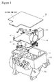
- Figure 1 is a view showing a configuration of an electric compressor 10 in accordance with this embodiment.
- a motor (not shown) and a scroll compressor (not shown) are accommodated in a lower accommodation chamber 11a of a housing 11, and an inverter board (control board) 12 is accommodated in an upper accommodation chamber 11b, which has an upward opening, of the housing 11.
- the inverter board 12 comprises a capacitor 13 and a reactor 14, which are used for smoothing a dc voltage supplied to the inverter board 12, a control circuit board 15 for controlling the application of a high ac voltage to the motor, and a power board 16 for converting a high-voltage direct current to a high-voltage alternating current and applying the alternating current to the motor to rotationally drive the motor.
- the upward opening of the upper accommodation chamber 11b is covered with a cover 20.
- a cover 20 The upward opening of the upper accommodation chamber 11b is covered with a cover 20.
- a plurality of modes of the cover 20 are explained.
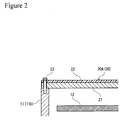
- a cover 20A shown in Figure 2 has an external shape that corresponds to the shape of the opening of the upper accommodation chamber 11b, and is configured so that a conductive material layer 21 formed of a conductive material such as aluminum or an iron-based material and an insulating material layer 22 formed of an insulating material such as a resin or a rubber-based material are laminated.
- a conductive material layer 21 formed of a conductive material such as aluminum or an iron-based material
- an insulating material layer 22 formed of an insulating material such as a resin or a rubber-based material
- the cover 20A can be provided in the state in which the insulating material layer 22 is directed to the outside of the housing 11, and the conductive material layer 21 is directed to the inside of the housing 11.
- the cover 20A is attached to the housing 11 with bolts 23 or the like.
- the insulating material layer 22 so as to be directed to the outside of the housing 11, even if the terminal of, for example, a battery or a booster cable, the terminal of electronic equipment, or the like is inadvertently brought into contact with the cover 20A in the engine room of a vehicle, insulation from a high voltage flowing in the inverter board 12 can be attained, and an electrical short circuit with the inverter board 12 can be prevented.
- the insulating material layer 22 is formed of a resin or a rubber-based material, vibration of the conductive material layer 21 of the cover 20A produced by the vibration caused by the rotation of the compressor can be suppressed, and thereby vibration and noise of the electric compressor 10 can be reduced.
- a cover 20B shown in Figure 3 differs from the cover 20A shown in Figure 2 in that the lamination sequence of the conductive material layer 21 and the insulating material layer 22 is reversed. That is to say, the cover 20B configured by laminating the conductive material layer 21 formed of a conductive material and the insulating material layer 22 is provided in the state in which the insulating material layer 22 is directed to the inside of the housing 11, and the conductive material layer 21 is directed to the outside of the housing 11.
- cover 20B electrical continuity between the conductive material layer 21 of the cover 20B and the housing 11 is made by the bolts 23 for attaching the cover 20B to the housing 11.
- the conductive material layer 21 of the cover 20B can be insulated from the inverter board 12 to which a high voltage is applied, so that the distance between the inverter board 12 and the conductive material layer 21 (insulation distance) can be decreased.
- the housing 11, that is, the electric compressor 10 can be made small in size.
- this insulating material layer 22 is provided so as to be interposed between the conductive material layer 21 and an outer peripheral edge part 11c of the housing 11, and is formed of a resin or a rubber-based material that is softer than the conductive material layer 21 and the housing 11, so that the insulating material layer 22 functions as a packing between the cover 20B and the housing 11.
- the sealing ability between the cover 20B and the housing 11 is enhanced, and thereby the waterproofness and dustproofness in the housing 11 can be improved.
- vibration of the conductive material layer 21 of the cover 20B produced by the vibration caused by the rotation of the compressor can be suppressed, and thereby vibration and noise of the electric compressor 10 can be reduced.
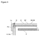
- a cover 20c shown in Figure 4 is configured so as to have a shape such that the conductive material layer 21 is in direct contact with the housing 11 in the outer peripheral part of the cover 20B shown in Figure 3 .
- the cover 20C is configured by laminating the conductive material layer 21 formed of a conductive material and the insulating material layer 22, and is provided in the state in which the insulating material layer 22 is directed to the inside of the housing 11 and the conductive material layer 21 is directed to the outside of the housing 11.
- the conductive material layer 21 is integrally formed with an extending part 21a that intersects at right angles with a surface 20f of the main part of the cover 20C and extends to the housing 11 side.
- This extending part 21a may be formed continuously throughout the entire periphery of the outer peripheral part of the cover 20C, or may be formed at a plurality of locations.
- the cover 20C is fixed to the housing 11 with bolts 23 or the like. It is preferable that the extending part 21a of the conductive material layer 21 be in direct contact with the outer peripheral surface of the housing 11 in the state in which the cover 20C is fixed to the housing 11.
- the conductive material layer 21 of the cover 20C can be insulated from the inverter board 12 to which a high voltage is applied, so that the electric compressor 10 can be made small in size.
- the insulating material layer 22 is provided so as to be interposed between the conductive material layer 21 and the outer peripheral edge part 11c of the housing 11, so that the insulating material layer 22 functions as a packing. Thereby, the waterproofness and dustproofness in the housing 11 can be improved.
- vibration of the conductive material layer 21 can be suppressed, and thereby vibration and noise of the electric compressor 10 can be reduced.
- the extending part 21a is located on the outer periphery side of the insulating material layer 22, electromagnetic noise is restrained from leaking from the insulating material layer 22 interposed between the conductive material layer 21 and the housing 11 to the side, so that the electromagnetic noise suppressing effect is further enhanced. Also, if the extending part 21a formed in the outer peripheral part of the conductive material layer 21 is brought into direct contact with the outer peripheral surface of the housing 11, electrical continuity between the conductive material layer 21 of the cover 20C and the housing 11 can be increased. Also, since being formed so as to intersect at right angles with the surface 21f of the main part of the conductive material layer 21, the extending part 21a also functions as a reinforcement for the cover 20C. Thereby, the thickness of the conductive material layer 21 can be decreased, which leads to a reduction in weight of the electric compressor 10.
- the insulating material layer 22 may be provided not only on either one surface side of the conductive material layer 21 but also on both surface sides thereof. In the latter case, the effects of both of the covers 20A and 20B shown in Figures 2 and 3 can be achieved.
Applications Claiming Priority (2)
| Application Number | Priority Date | Filing Date | Title |
|---|---|---|---|
| JP2007055210A JP2008215236A (ja) | 2007-03-06 | 2007-03-06 | 車載用電動圧縮機 |
| PCT/JP2007/069099 WO2008108023A1 (fr) | 2007-03-06 | 2007-09-28 | Compresseur électrique pour véhicule |
Publications (1)
| Publication Number | Publication Date |
|---|---|
| EP2116724A1 true EP2116724A1 (fr) | 2009-11-11 |
Family
ID=39737924
Family Applications (1)
| Application Number | Title | Priority Date | Filing Date |
|---|---|---|---|
| EP07828840A Withdrawn EP2116724A1 (fr) | 2007-03-06 | 2007-09-28 | Compresseur électrique pour véhicule |
Country Status (5)
| Country | Link |
|---|---|
| US (1) | US20100074772A1 (fr) |
| EP (1) | EP2116724A1 (fr) |
| JP (1) | JP2008215236A (fr) |
| CA (1) | CA2668609A1 (fr) |
| WO (1) | WO2008108023A1 (fr) |
Cited By (5)
| Publication number | Priority date | Publication date | Assignee | Title |
|---|---|---|---|---|
| EP2395634A1 (fr) | 2010-06-11 | 2011-12-14 | Axoris | Dispositif applicatif intégré dans une structure mécanique motorisée pour la manutention et convoyage de palettes et l'installation résultante |
| EP2733352A1 (fr) * | 2012-11-15 | 2014-05-21 | Kabushiki Kaisha Toyota Jidoshokki | Compresseur motorisé |
| EP2692984A3 (fr) * | 2012-08-03 | 2016-04-13 | Kabushiki Kaisha Toyota Jidoshokki | Compresseur motorisé |
| EP2500516A3 (fr) * | 2011-03-16 | 2016-05-18 | Kabushiki Kaisha Toyota Jidoshokki | Compresseur |
| EP3768051A4 (fr) * | 2018-03-12 | 2021-03-10 | Nissan Motor Co., Ltd. | Boîtier de composant électronique |
Families Citing this family (25)
| Publication number | Priority date | Publication date | Assignee | Title |
|---|---|---|---|---|
| JP5107114B2 (ja) * | 2008-03-28 | 2012-12-26 | 三菱重工業株式会社 | インバータ一体型電動圧縮機 |
| KR101069663B1 (ko) * | 2009-03-04 | 2011-10-05 | 주식회사 두원전자 | 인버터가 장착된 전동식 압축기 |
| JP5108977B1 (ja) * | 2012-01-23 | 2012-12-26 | シナノケンシ株式会社 | 圧縮機又は真空機 |
| JP5622777B2 (ja) | 2012-03-23 | 2014-11-12 | シナノケンシ株式会社 | 圧縮機又は真空機 |
| JP5915384B2 (ja) * | 2012-05-30 | 2016-05-11 | 株式会社豊田自動織機 | 電動圧縮機 |
| JP2013249741A (ja) * | 2012-05-30 | 2013-12-12 | Toyota Industries Corp | 電動圧縮機 |
| JP5683536B2 (ja) | 2012-06-08 | 2015-03-11 | 株式会社豊田自動織機 | 電動圧縮機 |
| JP6046983B2 (ja) * | 2012-11-05 | 2016-12-21 | アスモ株式会社 | 電動ポンプ |
| JP6083294B2 (ja) * | 2013-03-28 | 2017-02-22 | 株式会社豊田自動織機 | 電動圧縮機及びその製造方法 |
| JP5751291B2 (ja) * | 2013-07-30 | 2015-07-22 | 株式会社豊田自動織機 | 電動圧縮機 |
| JP5888298B2 (ja) | 2013-08-23 | 2016-03-16 | 株式会社豊田自動織機 | 電動圧縮機 |
| JP6320813B2 (ja) * | 2014-03-20 | 2018-05-09 | 三菱重工オートモーティブサーマルシステムズ株式会社 | インバータ一体型電動圧縮機 |
| JP2016180402A (ja) * | 2015-03-25 | 2016-10-13 | 株式会社豊田自動織機 | 電動圧縮機 |
| KR102202419B1 (ko) | 2015-04-17 | 2021-01-13 | 한온시스템 주식회사 | 전동 압축기 |
| DE102015214785B3 (de) * | 2015-08-03 | 2016-08-04 | Magna powertrain gmbh & co kg | Elektrischer Verdichter |
| JP2017072071A (ja) * | 2015-10-07 | 2017-04-13 | 株式会社豊田自動織機 | 電動圧縮機 |
| CN106787460B (zh) * | 2015-11-18 | 2019-03-29 | 建准电机工业股份有限公司 | 马达与转接板的结合构造及用于马达的转接板 |
| JP2019152199A (ja) * | 2018-03-06 | 2019-09-12 | アイシン精機株式会社 | 電動ポンプ |
| JP7403230B2 (ja) * | 2019-04-01 | 2023-12-22 | 三菱重工サーマルシステムズ株式会社 | 電動圧縮機 |
| JP7306282B2 (ja) * | 2020-01-30 | 2023-07-11 | 株式会社豊田自動織機 | 電動圧縮機 |
| WO2021171779A1 (fr) * | 2020-02-28 | 2021-09-02 | 日立Astemo株式会社 | Dispositif de commande électronique |
| CN112583194A (zh) * | 2020-12-16 | 2021-03-30 | 一汽奔腾轿车有限公司 | 一种低噪声电动车电机端盖 |
| JP2022113509A (ja) * | 2021-01-25 | 2022-08-04 | 日本電産トーソク株式会社 | 電動ポンプ |
| US20230108070A1 (en) * | 2021-10-01 | 2023-04-06 | GM Global Technology Operations LLC | Bubble cover to reduce noise and vibration |
| KR20230137148A (ko) * | 2022-03-21 | 2023-10-04 | 한온시스템 주식회사 | 전동 압축기 |
Family Cites Families (16)
| Publication number | Priority date | Publication date | Assignee | Title |
|---|---|---|---|---|
| US4169360A (en) * | 1977-05-16 | 1979-10-02 | Sankyo Electric Company Limited | Refrigerant compressors for automotive air conditioning refrigerating systems |
| JPS6115798U (ja) * | 1984-07-04 | 1986-01-29 | 富士電機株式会社 | 電子装置収納箱 |
| JPS61126385A (ja) * | 1984-11-22 | 1986-06-13 | Sawafuji Electric Co Ltd | 振動型圧縮機 |
| DE3616149A1 (de) * | 1985-05-16 | 1986-11-20 | Sawafuji Electric Co., Ltd., Tokio/Tokyo | System zur steuerung des betriebs eines vibrationskompressors |
| JP3086819B2 (ja) | 1990-07-20 | 2000-09-11 | セイコーエプソン株式会社 | 空気調和機用モータ一体型圧縮機 |
| JPH05304386A (ja) * | 1990-12-28 | 1993-11-16 | Nec Corp | 高周波回路用筐体 |
| JPH10257708A (ja) * | 1997-03-10 | 1998-09-25 | Toshiba Fa Syst Eng Kk | インバータ一体形モータ |
| JP2000291557A (ja) * | 1999-04-07 | 2000-10-17 | Sanden Corp | 電動式圧縮機 |
| JP4235396B2 (ja) * | 2002-03-29 | 2009-03-11 | 真和工業株式会社 | インバータカバー |
| JP2004100684A (ja) * | 2002-07-15 | 2004-04-02 | Toyota Industries Corp | モータ駆動回路及び電動コンプレッサ |
| JP2004100683A (ja) * | 2002-07-15 | 2004-04-02 | Toyota Industries Corp | 電動コンプレッサ |
| JP2004228126A (ja) * | 2003-01-20 | 2004-08-12 | Denso Corp | 電子回路用ハウジング |
| JP3794392B2 (ja) * | 2003-02-25 | 2006-07-05 | 日産自動車株式会社 | 電気自動車の駆動ユニット |
| JP4372479B2 (ja) * | 2003-08-05 | 2009-11-25 | 真和工業株式会社 | インバータカバー |
| JP2006245421A (ja) * | 2005-03-04 | 2006-09-14 | Nissan Motor Co Ltd | 冷却筐体 |
| JP4756935B2 (ja) * | 2005-06-29 | 2011-08-24 | 本田技研工業株式会社 | コンデンサ搭載型インバータユニット |
-
2007
- 2007-03-06 JP JP2007055210A patent/JP2008215236A/ja active Pending
- 2007-09-28 CA CA002668609A patent/CA2668609A1/fr not_active Abandoned
- 2007-09-28 US US12/513,522 patent/US20100074772A1/en not_active Abandoned
- 2007-09-28 EP EP07828840A patent/EP2116724A1/fr not_active Withdrawn
- 2007-09-28 WO PCT/JP2007/069099 patent/WO2008108023A1/fr active Application Filing
Non-Patent Citations (1)
| Title |
|---|
| See references of WO2008108023A1 * |
Cited By (9)
| Publication number | Priority date | Publication date | Assignee | Title |
|---|---|---|---|---|
| EP2395634A1 (fr) | 2010-06-11 | 2011-12-14 | Axoris | Dispositif applicatif intégré dans une structure mécanique motorisée pour la manutention et convoyage de palettes et l'installation résultante |
| FR2961360A1 (fr) * | 2010-06-11 | 2011-12-16 | Axoris | Dispositif applicatif integre dans une structure mecanique motorisee |
| EP2500516A3 (fr) * | 2011-03-16 | 2016-05-18 | Kabushiki Kaisha Toyota Jidoshokki | Compresseur |
| EP2692984A3 (fr) * | 2012-08-03 | 2016-04-13 | Kabushiki Kaisha Toyota Jidoshokki | Compresseur motorisé |
| EP2733352A1 (fr) * | 2012-11-15 | 2014-05-21 | Kabushiki Kaisha Toyota Jidoshokki | Compresseur motorisé |
| CN103821691A (zh) * | 2012-11-15 | 2014-05-28 | 株式会社丰田自动织机 | 马达驱动压缩机 |
| CN103821691B (zh) * | 2012-11-15 | 2016-06-15 | 株式会社丰田自动织机 | 马达驱动压缩机 |
| EP3768051A4 (fr) * | 2018-03-12 | 2021-03-10 | Nissan Motor Co., Ltd. | Boîtier de composant électronique |
| US11439048B2 (en) | 2018-03-12 | 2022-09-06 | Nissan Motor Co., Ltd. | Electronic component housing |
Also Published As
| Publication number | Publication date |
|---|---|
| WO2008108023A1 (fr) | 2008-09-12 |
| CA2668609A1 (fr) | 2008-09-12 |
| US20100074772A1 (en) | 2010-03-25 |
| JP2008215236A (ja) | 2008-09-18 |
Similar Documents
| Publication | Publication Date | Title |
|---|---|---|
| EP2116724A1 (fr) | Compresseur électrique pour véhicule | |
| CN109155595B (zh) | 车载用电动压缩机 | |
| CN108183017B (zh) | 电感器以及dc-dc转换器 | |
| JP5117843B2 (ja) | インバータ一体型電動圧縮機 | |
| US9866127B2 (en) | Electrical power converting device | |
| CN109121458B (zh) | 车载用的电力变换装置 | |
| JP5733945B2 (ja) | インバータモジュールおよびインバータ一体型電動圧縮機 | |
| EP2899866B1 (fr) | Dispositif de conversion de puissance à monter dans un véhicule alimenté par une puissance électrique | |
| KR20110135233A (ko) | 자동차의 인버터용 커패시터 | |
| EP2189661A1 (fr) | Compresseur électrique à onduleur intégré | |
| EP2372156A1 (fr) | Compresseur électrique à inverseur intégré monté sur véhicule | |
| WO2003047894A1 (fr) | Conditionneur d'air | |
| WO2016136115A1 (fr) | Dispositif de conversion de courant électrique | |
| US20030094920A1 (en) | Inverter-equipped motor | |
| KR102623212B1 (ko) | 공기 압축기 | |
| EP2197097B1 (fr) | Compresseur électrique intégrant un inverseur et son composant de bobine pour un dispositif d'inversion | |
| KR101832218B1 (ko) | 전동 압축기 | |
| US10236121B2 (en) | Capacitor unit and electric power conversion device | |
| JP2010209788A (ja) | インバータ一体型電動圧縮機 | |
| JP2013021918A (ja) | インバータ一体型電動圧縮機 | |
| JP5653695B2 (ja) | ガスケット及び電動圧縮機 | |
| CN112469899A (zh) | 电动压缩机 | |
| US20170104392A1 (en) | Electric compressor | |
| KR101701553B1 (ko) | 전동 압축기용 인버터 모듈 | |
| JP2021158228A (ja) | 車載電力変換装置 |
Legal Events
| Date | Code | Title | Description |
|---|---|---|---|
| PUAI | Public reference made under article 153(3) epc to a published international application that has entered the european phase |
Free format text: ORIGINAL CODE: 0009012 |
|
| 17P | Request for examination filed |
Effective date: 20090511 |
|
| AK | Designated contracting states |
Kind code of ref document: A1 Designated state(s): AT BE BG CH CY CZ DE DK EE ES FI FR GB GR HU IE IS IT LI LT LU LV MC MT NL PL PT RO SE SI SK TR |
|
| DAX | Request for extension of the european patent (deleted) | ||
| STAA | Information on the status of an ep patent application or granted ep patent |
Free format text: STATUS: THE APPLICATION IS DEEMED TO BE WITHDRAWN |
|
| 18D | Application deemed to be withdrawn |
Effective date: 20150401 |