EP2116435B1 - Steuervorrichtung für arbeitsfahrzeug - Google Patents
Steuervorrichtung für arbeitsfahrzeug Download PDFInfo
- Publication number
- EP2116435B1 EP2116435B1 EP07850504.7A EP07850504A EP2116435B1 EP 2116435 B1 EP2116435 B1 EP 2116435B1 EP 07850504 A EP07850504 A EP 07850504A EP 2116435 B1 EP2116435 B1 EP 2116435B1
- Authority
- EP
- European Patent Office
- Prior art keywords
- brake
- parking brake
- control system
- work vehicle
- clutch
- Prior art date
- Legal status (The legal status is an assumption and is not a legal conclusion. Google has not performed a legal analysis and makes no representation as to the accuracy of the status listed.)
- Active
Links
Images


Classifications
-
- B—PERFORMING OPERATIONS; TRANSPORTING
- B60—VEHICLES IN GENERAL
- B60T—VEHICLE BRAKE CONTROL SYSTEMS OR PARTS THEREOF; BRAKE CONTROL SYSTEMS OR PARTS THEREOF, IN GENERAL; ARRANGEMENT OF BRAKING ELEMENTS ON VEHICLES IN GENERAL; PORTABLE DEVICES FOR PREVENTING UNWANTED MOVEMENT OF VEHICLES; VEHICLE MODIFICATIONS TO FACILITATE COOLING OF BRAKES
- B60T13/00—Transmitting braking action from initiating means to ultimate brake actuator with power assistance or drive; Brake systems incorporating such transmitting means, e.g. air-pressure brake systems
- B60T13/10—Transmitting braking action from initiating means to ultimate brake actuator with power assistance or drive; Brake systems incorporating such transmitting means, e.g. air-pressure brake systems with fluid assistance, drive, or release
- B60T13/66—Electrical control in fluid-pressure brake systems
- B60T13/68—Electrical control in fluid-pressure brake systems by electrically-controlled valves
- B60T13/686—Electrical control in fluid-pressure brake systems by electrically-controlled valves in hydraulic systems or parts thereof
-
- B—PERFORMING OPERATIONS; TRANSPORTING
- B60—VEHICLES IN GENERAL
- B60T—VEHICLE BRAKE CONTROL SYSTEMS OR PARTS THEREOF; BRAKE CONTROL SYSTEMS OR PARTS THEREOF, IN GENERAL; ARRANGEMENT OF BRAKING ELEMENTS ON VEHICLES IN GENERAL; PORTABLE DEVICES FOR PREVENTING UNWANTED MOVEMENT OF VEHICLES; VEHICLE MODIFICATIONS TO FACILITATE COOLING OF BRAKES
- B60T7/00—Brake-action initiating means
- B60T7/12—Brake-action initiating means for automatic initiation; for initiation not subject to will of driver or passenger
-
- B—PERFORMING OPERATIONS; TRANSPORTING
- B60—VEHICLES IN GENERAL
- B60T—VEHICLE BRAKE CONTROL SYSTEMS OR PARTS THEREOF; BRAKE CONTROL SYSTEMS OR PARTS THEREOF, IN GENERAL; ARRANGEMENT OF BRAKING ELEMENTS ON VEHICLES IN GENERAL; PORTABLE DEVICES FOR PREVENTING UNWANTED MOVEMENT OF VEHICLES; VEHICLE MODIFICATIONS TO FACILITATE COOLING OF BRAKES
- B60T13/00—Transmitting braking action from initiating means to ultimate brake actuator with power assistance or drive; Brake systems incorporating such transmitting means, e.g. air-pressure brake systems
- B60T13/10—Transmitting braking action from initiating means to ultimate brake actuator with power assistance or drive; Brake systems incorporating such transmitting means, e.g. air-pressure brake systems with fluid assistance, drive, or release
- B60T13/66—Electrical control in fluid-pressure brake systems
- B60T13/68—Electrical control in fluid-pressure brake systems by electrically-controlled valves
-
- B—PERFORMING OPERATIONS; TRANSPORTING
- B60—VEHICLES IN GENERAL
- B60T—VEHICLE BRAKE CONTROL SYSTEMS OR PARTS THEREOF; BRAKE CONTROL SYSTEMS OR PARTS THEREOF, IN GENERAL; ARRANGEMENT OF BRAKING ELEMENTS ON VEHICLES IN GENERAL; PORTABLE DEVICES FOR PREVENTING UNWANTED MOVEMENT OF VEHICLES; VEHICLE MODIFICATIONS TO FACILITATE COOLING OF BRAKES
- B60T7/00—Brake-action initiating means
- B60T7/02—Brake-action initiating means for personal initiation
-
- B—PERFORMING OPERATIONS; TRANSPORTING
- B60—VEHICLES IN GENERAL
- B60T—VEHICLE BRAKE CONTROL SYSTEMS OR PARTS THEREOF; BRAKE CONTROL SYSTEMS OR PARTS THEREOF, IN GENERAL; ARRANGEMENT OF BRAKING ELEMENTS ON VEHICLES IN GENERAL; PORTABLE DEVICES FOR PREVENTING UNWANTED MOVEMENT OF VEHICLES; VEHICLE MODIFICATIONS TO FACILITATE COOLING OF BRAKES
- B60T7/00—Brake-action initiating means
- B60T7/02—Brake-action initiating means for personal initiation
- B60T7/08—Brake-action initiating means for personal initiation hand actuated
- B60T7/085—Brake-action initiating means for personal initiation hand actuated by electrical means, e.g. travel, force sensors
-
- B—PERFORMING OPERATIONS; TRANSPORTING
- B60—VEHICLES IN GENERAL
- B60T—VEHICLE BRAKE CONTROL SYSTEMS OR PARTS THEREOF; BRAKE CONTROL SYSTEMS OR PARTS THEREOF, IN GENERAL; ARRANGEMENT OF BRAKING ELEMENTS ON VEHICLES IN GENERAL; PORTABLE DEVICES FOR PREVENTING UNWANTED MOVEMENT OF VEHICLES; VEHICLE MODIFICATIONS TO FACILITATE COOLING OF BRAKES
- B60T8/00—Arrangements for adjusting wheel-braking force to meet varying vehicular or ground-surface conditions, e.g. limiting or varying distribution of braking force
Definitions
- the present invention relates to a control system for a work vehicle such as a wheel hydraulic excavator and a wheel loader.
- the brake release device in patent reference literature 1 includes a first and a second clutch devices in a transmission, engages both of the clutch devices in response to an operation instruction for parking brake so as to lock the transmission, and activates the parking brake.
- Patent reference literature 1 Japanese Laid Open Patent Publication No. 2002-79931 (equivalent to EP 1321340 ).
- Patent reference literature 2 Japanese Laid Open Patent Publication No. H8-48222 discloses a stop maintenance device for a vehicle which maintains the stopping state of a vehicle during vehicle stop by a control portion operating a braking force increase means under the conditions of vehicle stop being detected and parking brake operation being detected.
- Patent reference literature 3 discloses a motor vehicle having a service brake, and a parking brake which has a time lag between its initial activation and full operation, in which a controller automatically decides upon when to trigger the initial activation of the parking brake.
- the negative-type parking brake however, has a time lag between output of an operation instruction for parking brake and full operation of the parking brake. This bothers an operator to keep operating a brake pedal until the parking brake fully works, for instance, when the operator wishes to operate the parking brake while going downhill.
- a control system for a work vehicle comprising: a negative-type parking brake device that starts operating in response to a parking brake instruction, with the parking brake device having a time lag between the parking brake instruction and full operation of the parking brake device; an output device that outputs the parking brake instruction; and a service brake device that operates in response to an operation of a brake pedal by an operator; characterized in that the output device comprises a parking brake switch operated by the operator, and in that the control system further comprises a brake control device that operates the service brake device regardless of a pedal operation by the operator when the parking brake instruction is output from the parking brake switch, until a parking brake force increases to a predetermined value.
- the brake control device operates the service brake device for a predetermined length of time when the parking brake instruction is output from the output device.
- the predetermined length of time is set to a length of time required from when the parking brake device starts operating in response to an output of the parkingbrake instruction until when parking brake force increases to a predetermined value.
- a pedal operation detection device that detects an operation of the brake pedal may be further provided and the brake control device may operate the brake device regardless of the pedal operation by the operator when a predetermined pressing operation is detectedby the pedal operation detection device, even if the parking brake instruction is not output from the output device.
- the predetermined pressing operation is a maximum pressing operation.
- a vehicle speed detection device that detects a vehicle speed may be further provided and the brake control device may allow an operation of the service brake device upon an output of the parking brake instruction when the vehicle speed detected by the vehicle speed detection device is less than a predetermined value, and disallow an operation of the service brake device upon an output of the parking brake instruction when the vehicle speed is more than the predetermined value.
- the parking brake device may comprise a transmission that is provided with a first negative-type clutch device and a second negative-type clutch device that transmit power for traveling to an axle; and the transmission may engage simultaneously the first clutch device and the second clutch device so as to stop rotation of the axle, when the parking brake instruction is output.
- Each of the first clutch device and the second clutch device may be engaged by biasing force of a spring and be released by oil pressure.
- the transmission When the first clutch device is released and the second clutch device is engaged, the transmission may be set to a first gear ratio, and when the first clutch device is engaged and the second clutch device is released, the transmission may be set to a second gear ratio which is smaller than the first gear ratio.
- a traveling work vehicle comprises the control system described above; a traveling device that rotates wheels using a hydraulic motor; and an excavating device.
- a service brake device is operated regardless of the pedal operation by an operator when a parking brake instruction is output. This allows the operator to operate the parking brake easily without operating the brake pedal, for example, when going downhill.
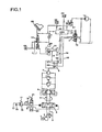
- FIG. 1 is a diagram of a control system according to the present embodiment, showing mainly a hydraulic circuit for traveling.
- the control system is provided in a work vehicle equipped with tires for traveling in workplaces or open roads.
- This sort of work vehicle includes a hydraulic excavator, a wheel loader, and so on, and is provided with an excavating device including a boom and a bucket.
- the excavating device is driven by a hydraulic actuator such as a hydraulic cylinder.
- Direction and flow rate of oil discharged from a main pump 2 that is driven by an engine (prime mover) 1 are controlled by a control valve 3.
- the discharged oil passes through a center joint 5 and is supplied to a traveling motor 7 via a counter balance valve 6.
- a rotation speed of the traveling motor 7 is changed by a transmission 8 and is transmitted to tires 11 via a shaft 9 and an axle 10. A work vehicle thus travels.
- the transmission 8 which is publicly known, includes a planetary reduction mechanism that consists of a sun gear, a planetary gear and a ring gear, and clutches 81 and 82 that are provided to the sun gear and the ring gear respectively.
- Each of the clutches 81 and 82 is provided with a clutch cylinder that includes a spring.
- the clutch cylinder is pressed onto a disk by biasing force of the spring so as to engage the corresponding clutch 81 or 82. Pressing force of the clutch cylinder is eliminated by oil pressure from a hydraulic power source 12 that acts against spring force so as to release the clutch 81 or 82.
- the oil pressure that acts on the clutches 81 and 82 is controlled by drive of a solenoid switch valve 13.
- a sort of clutch that is engaged by biasing force of a spring and is released by oil pressure is called a negative-type clutch.
- the solenoid switch valve 13 is switched over in response to a control signal from a CPU 30 (controller). It should be noted that although the controller includes a processing unit that includes the CPU 30, ROM, RAM, and other peripheral circuits, only the CPU 30 is shown in Fig. 1 as a representative of the controller.
- the solenoid switch valve 13 When the solenoid switch valve 13 is switched to position A, pressure oil from the hydraulic power source 12 acts on the clutch 81 via a line 14. This releases the clutch 81 and engages the clutch 82 so as to set the transmission 8 to a predefined gear ratio R1 (low gear) . Power for traveling by rotation of the traveling motor 7 is transmitted to the shaft 9, enabling the vehicle to travel in a first speed with low speed and high torque.
- the clutches 81 and 82 that stop rotation of the shaft 9 are used for a parking brake.
- either the clutch 81 or the clutch 82 is released by acting pressure oil (brake release pressure) on either the clutch 81 or the clutch 82.
- a sort of brake that is operated by biasing force of a spring and is released by oil pressure is called a negative-type parking brake.
- a pilot circuit for traveling includes a pilot hydraulic power source 16 that is driven by the engine 1 and generates pressure oil, a traveling pilot valve 18 that generates pilot secondary pressure in response to depressing of an accelerator pedal 17, a slow return valve 19 that is provided after the pilot valve 18 and delays return oil to the pilot valve 18, and a forward-reverse switching valve 20 for selecting forward travel, backward travel, or neutral of the vehicle, which is connected to the slow return valve 19.
- the forward-reverse switching valve 20 is switched over by operation of a control lever 21. Pilot pressure from the pilot hydraulic power source 16 acts on a pilot port of the control valve 3 and drives the control valve 3. Stroke of the control valve thus driven is controlled by the accelerator pedal 17 so as to adjust the travel speed of the vehicle.
- the work vehicle is provided with a known hydraulic foot brake (service brake) that exerts a decelerating force in response to operation of a brake pedal 22.
- a pilot circuit for the foot brake includes a pilot hydraulic power source 23 that is driven by the engine 1 and generates pressure oil, and a brake valve 24 that generates pilot secondary pressure (brake working pressure) in response to depressing of the brake pedal 22.
- the brake working pressure from the brake valve 24 acts on a front wheel brake device 25 and a rear wheel brake device 26.
- the brake devices 25 and 26 thus work in response to operation of the pedal and are used as a service brake during running.
- the brake valve 24 is connected with the hydraulic power source 12 through a solenoid valve 27.
- the solenoid valve 27 is switched over in response to a signal from the CPU 30.
- pilot pressure from the hydraulic power source 12 acts on the brake valve 24.
- the brake valve 24 is thus driven to cause pressure oil from the hydraulic power source 23 to act on the brake devices 25 and 26.
- the brake devices 25 and 26 thus work without the operator operating the brake pedal 22, and can be used as a work brake during working such as an excavating operation.
- the solenoid switch valve 13 and the solenoid valve 27 are controlled by the CPU 30.
- the CPU 30 is connected with a pressure sensor 31 that detects brake working pressure from the brake valve 24, that is, operation of the brake pedal 22, a parking brake switch 32 that instructs operation of the parkingbrake, a speed change switch 33 that instructs to change speedbetweenthe first speed and the secondspeed, andavehicle speed sensor 34 that detects vehicle speed.
- the following processing is performed in the CPU 30.
- Fig. 2 is a flowchart that shows an example of processing performed in the CPU 30.
- the flowchart starts in response to, for instance, switching on an engine key switch.
- the solenoid valve 27 is switched to position B.
- step S1 it is determined whether the parking brake switch 32 is on or not. If it is determined that the parking brake switch 32 is off, operation proceeds to step S6 so as to determine operation of the speed change switch 33. If it is determined that the speed change switch 33 instructs to select the first speed, operation proceeds to step S7, and the solenoid switch valve 13 is switched to position A. If it is determined that the speed change switch 33 instructs to select the second speed, operation proceeds to step S8, and the solenoid switch valve 13 is switched to position B.
- step S1 If, on the other hand, it is determined that the parking brake switch 32 is turned on in step S1, operation proceeds to step S2, and the solenoid valve 27 is switched to position A so as to operate a work brake. Then, the solenoid switch valve 13 is switched to position C in step S3 so that pressure oil from the hydraulic power source 12 is stopped acting on the clutches 81 and 82.
- step S4 it is determined whether or not a predetermined length of time has passed since the parking brake switch 32 is switched on.
- the predetermined length of time is set in advance to substantially correspond to a length of time between when the parking brake switch 32 is switched on and when pressure in the clutches 81 and 82 becomes equal to a reservoir pressure, in other words, a length of time from when the parking brake starts operating until when the parking brake operates fully. If step S4 is negated, operation returns to step S2, and the same processing is repeated. If step S4 is affirmed, operation proceeds to step S5, and the solenoid valve 27 is switched to position B so as to release the work brake.
- step S7 when the speed change switch 33 instructs to select the first speed while the parking brake switch 32 is switched off, the solenoid switch valve 13 is switched to position A, and pressure oil from the hydraulic power source 12 acts on the clutch 81 via the line 14 (step S7) .
- step S8 When the speed change switch 33 instructs to select the second speed, the solenoid switch valve 13 is switched to position B, and pressure oil from the hydraulic power source 12 acts on the clutch 82 via the line 15 (step S8) .
- Fig. 3 (a) Operations at parking are now described with a timeline chart in Fig. 3 (a) .
- work brake indicates oil pressure that acts on the brake devices 25 and26
- parking brake indicates oil pressure that acts on the clutches 81 and 82.
- Brake force of the work brake increases with an increase in oil pressure that acts on the brake devices 25 and 26, while brake force of the parking brake increases with an decrease in oil pressure that acts on the clutches 81 and 82.
- the work brake is switched on by the operation of the parking brake switch 32 and is switched off after a predetermined length of time so as to stop motion of the vehicle even before the parking brake operates fully. This prevents the vehicle from moving undesirably when the parking brake is operated, for example, on a slope. An operator thus does not have to continuously operate the brake pedal 22 until the parking brake works fully and operation of the parking brake is facilitated.
- a predetermined length of time is not limited to that described above.
- the flow velocity of pressure oil from the clutches 81 and 82 that is, response of the parking brake varies dependingon oil temperature.
- An oil temperature sensor may detect the oil temperature in the lines 14 and 15 so as to vary a predetermined length of time for the operation of the work brake depending on the oil temperature. In this case, as shown in Fig. 3 (b) , the length of time before the parking brake operates fully is reduced since the oil becomes less viscous as the oil temperature becomes higher. Therefore, the predetermined length of time may be set shorter if the oil temperature is higher.
- the solenoid valve 27 and the solenoid switch valve 13 are switched over immediately after the parking brake switch 32 is switched on, they may be switched over when the vehicle speed sensor 34 detects a vehicle speed of less than a predetermined speed.
- the vehicle speed sensor 34 detects a vehicle speed of less than a predetermined speed.
- the solenoid valve 27 is switched to position A in response to the work brake switch being switched on so as to operate the work brake.
- the solenoid valve 27 may be switched to position A when a predetermined pedal operation is performed or when a predetermined vehicle state is realized.
- the solenoid valve 27 may be switched to position A and the work brake may be operated, if the brake pedal 22 is pressed more than a predetermined amount (for example, in a maximum pressing operation), for instance, in a state where the vehicle speed is less than a predetermined speed.
- a predetermined amount for example, in a maximum pressing operation
- the solenoid valve 27 may be switched to position B and the work brake may be released, when the brake pedal 22 is pressed again more than a predetermined amount after the operation of the brake pedal 22 is stopped with the work brake operating.
- the pressing operation on the brake pedal 22 with more than a predetermined amount is detected by the pressure sensor 31.
- the work brake may be operated or released when the pressing operation with more than the predetermined amount is performed continuously for a predetermined length of time. This does not allow the work brake to be operated or released even if the operator operates the brake pedal 22 momentarily. Frequent operation/release of the work brake is thus prevented.
- a pedal operation detection device other than a pressure sensor may be used.
- a parking brake device includes the clutch 81 (first clutch device) and the clutch 82 (second clutch device) of the transmission 8.
- a parking brake may be configured separately from the clutches 81 and 82.
- a configuration of a parking brake device is not limited to that described above.
- a parking brake instruction is to be output from the parking brake switch 32. However, it may be output from another output device.
- the solenoid valve 27 is to be switched over in response to the parking brake switch 32 being switched on, and the brake devices 25 and 26 are to be operated regardless of operation of the brake pedal 22.
- a configuration of a brake control device is not limited to that described above.
- a work brake may be configured separately from the brake devices 25 and 26.
- a service brake device may not necessarily be used as a work brake.
- a clutch device is configured to release the clutch 81 and engage the clutch 82 for setting the transmission 8 to the gear ratio R1 (first gear ratio), and to engage the clutch 81 and release the clutch 82 for setting the transmission 8 to a gear ratio R2 (second gear ratio) .
- a configuration of the clutch device is not limited to that described above.
- a length of time from when the parking brake starts working until when the parking brake works fully is set as a predetermined length of time, and the work brake (service brake device) is controlled to operate for the predetermined length of time.
- the predetermined length of time is not limited to that described above.
- a length of time until the parking brake force exceeds a certain level may be set as the predetermined length of time.
- Operations of the work brake may be controlled in accordance with a physical quantity correlative to the parking brake force. Parameter may be a physical quantity other than a length of time.
- the solenoid valve 27 may be switched to position B so as to switch the work brake off.
- the present invention is not limited to the control system for a work vehicle in accordance with the above embodiments as long as the characteristic features and functions of the present invention can be achieved.
Landscapes
- Engineering & Computer Science (AREA)
- Transportation (AREA)
- Mechanical Engineering (AREA)
- Regulating Braking Force (AREA)
- Operation Control Of Excavators (AREA)
- Braking Elements And Transmission Devices (AREA)
- Braking Systems And Boosters (AREA)
Claims (11)
- Steuerungssystem für ein Arbeitsfahrzeug, umfassend:eine selbsttätige Parkbremsvorrichtung (81, 82), die in Reaktion auf einen Parkbremsbefehl in Funktion tritt, wobei die Parkbremsvorrichtung eine Zeitverzögerung zwischen dem Parkbremsbefehl und der vollen Betätigung der Parkbremsvorrichtung hat;eine Ausgabevorrichtung, die den Parkbremsbefehl ausgibt; undeine Betriebsbremsvorrichtung (25, 26), die in Reaktion auf eine Betätigung eines Bremspedals (22) durch eine Bedienperson auslöst;dadurch gekennzeichnet, dassdie Ausgabevorrichtung einen Parkbremsschalter (32) umfasst, der von der Bedienperson betätigt wird, und dass das Steuerungssystem ferner umfasst:eine Bremssteuerungsvorrichtung (30), die die Betriebsbremsvorrichtung unabhängig von einer Pedalbetätigung durch die Bedienperson betätigt, wenn der Parkbremsbefehl von dem Parkbremsschalter (32) ausgegeben wird, bis eine Parkbremskraft auf einen vorbestimmten Wert steigt.
- Steuerungssystem für ein Arbeitsfahrzeug gemäß Anspruch 1, wobei:die Bremssteuerungsvorrichtung (30) die Betriebsbremsvorrichtung (25, 26) für einen vorbestimmten Zeitraum betätigt, wenn der Parkbremsbefehl von dem Parkbremsschalter (32) ausgegeben wird.
- Steuerungssystem für ein Arbeitsfahrzeug gemäß Anspruch 2, wobei:der vorbestimmte Zeitraum auf einen Zeitraum eingestellt wird, der von dem Zeitpunkt, zu dem die Parkbremsvorrichtung (81, 82) in Reaktion auf eine Ausgabe des Parkbremsbefehls in Funktion tritt, bis zu einem Zeitpunkt, zu dem die Parkbremskraft auf den vorbestimmten Wert zugenommen hat, benötigt wird.
- Steuerungssystem für ein Arbeitsfahrzeug gemäß Anspruch 2 oder Anspruch 3, ferner umfassend:eine Öltemperaturerfassungsvorrichtung, die eine Temperatur eines Öldrucks erfasst, der verursacht, dass ein Bremslösedruck auf die Parkbremsvorrichtung (81, 82) wirkt; wobei:die Bremssteuerungsvorrichtung (30) den vorbestimmten Zeitraum desto kürzer einstellt, je höher die von der Oltemperaturerfassungsvorrichtung erfasste Öltemperatur liegt.
- Steuerungssystem für ein Arbeitsfahrzeug gemäß einem der Ansprüche 1 bis 3, umfassend:eine Pedalbetätigungserfassungsvorrichtung (31), die eine Betätigung des Bremspedals erfasst; wobei:die Bremssteuerungsvorrichtung (30) die Bremsvorrichtung unabhängig von der Pedalbetätigung durch die Bedienperson betätigt, wenn von der Pedalbetätigungserfassungsvorrichtung eine vorbestimmte Druckbetätigung erfasst wurde, selbst wenn der Parkbremsbefehl nicht von dem Parkbremsschalter (32) ausgegeben wird.
- Steuerungssystem für ein Arbeitsfahrzeug gemäß Anspruch 5, wobei:die vorbestimmte Druckbetätigung eine maximale Druckbetätigung ist.
- Steuerungssystem für ein Arbeitsfahrzeug gemäß einem der Ansprüche 1 bis 6, ferner umfassend:eine Fahrzeuggeschwindigkeitserfassungsvorrichtung (34), die eine Fahrzeuggeschwindigkeit erfasst; wobei:die Bremssteuerungsvorrichtung (30) eine Betätigung der Betriebsbremsvorrichtung (25, 26) nach einer Ausgabe des Parkbremsbefehls zulässt, wenn die von der Fahrzeuggeschwindigkeitserfassungsvorrichtung erfasste Fahrzeuggeschwindigkeit kleiner als ein vorbestimmter Wert ist, und eine Betätigung der Betriebsbremsvorrichtung (25, 26) nach einer Ausgabe des Parkbremsbefehls nicht zulässt, wenn Fahrzeuggeschwindigkeit größer als ein vorbestimmter Wert ist.
- Steuerungssystem für ein Arbeitsfahrzeug gemäß einem der Ansprüche 1 bis 7, wobei:die Parkbremsvorrichtung (81, 82) ein Getriebe (8) umfasst, das mit einer ersten selbsttägigen Kupplungsvorrichtung (81) und einer zweiten selbsttägigen Kupplungsvorrichtung (82) ausgestattet ist, die eine Kraft zur Fortbewegung auf eine Achse (10) übertragen; unddas Getriebe gleichzeitig mit der ersten Kupplungsvorrichtung und der zweiten Kupplungsvorrichtung in Eingriff kommt, um so eine Drehung der Achse zu blockieren, wenn der Parkbremsbefehl ausgegeben wird.
- Steuerungssystem für ein Arbeitsfahrzeug gemäß Anspruch 8, wobei:die erste Kupplungsvorrichtung (81) und die zweite Kupplungsvorrichtung (82) jeweils durch eine Vorspannkraft einer Feder in Eingriff kommen und durch Öldruck ausgekuppelt werden.
- Steuerungssystem für ein Arbeitsfahrzeug gemäß Anspruch 8 oder Anspruch 9, wobei:wenn die erste Kupplungsvorrichtung (81) ausgekuppelt ist und die zweite Kupplungsvorrichtung (82) in Eingriff kommt, das Getriebe in ein erstes Untersetzungsverhältnis (R1) eingestellt ist, und wenn die erste Kupplungsvorrichtung (81) in Eingriff kommt und die zweite Kupplungsvorrichtung (82) ausgekuppelt ist, das Getriebe auf ein zweites Untersetzungsverhältnis (R2) eingestellt ist, das kleiner als das erste Untersetzungsverhältnis ist.
- Fahrbares Arbeitsfahrzeug, umfassend:eine Fahrvorrichtung, die unter der Verwendung eines Hydraulikmotors Räder in Drehung versetzt; undeine Baggervorrichtung, dadurch gekennzeichnet, dass es ferner umfasst:ein Steuerungssystem gemäß einem der Ansprüche 1 bis 10.
Applications Claiming Priority (2)
| Application Number | Priority Date | Filing Date | Title |
|---|---|---|---|
| JP2006337935A JP4956171B2 (ja) | 2006-12-15 | 2006-12-15 | 作業車両の制御装置 |
| PCT/JP2007/073953 WO2008072662A1 (ja) | 2006-12-15 | 2007-12-12 | 作業車両の制御装置 |
Publications (3)
| Publication Number | Publication Date |
|---|---|
| EP2116435A1 EP2116435A1 (de) | 2009-11-11 |
| EP2116435A4 EP2116435A4 (de) | 2011-03-23 |
| EP2116435B1 true EP2116435B1 (de) | 2013-09-04 |
Family
ID=39511679
Family Applications (1)
| Application Number | Title | Priority Date | Filing Date |
|---|---|---|---|
| EP07850504.7A Active EP2116435B1 (de) | 2006-12-15 | 2007-12-12 | Steuervorrichtung für arbeitsfahrzeug |
Country Status (6)
| Country | Link |
|---|---|
| US (1) | US8388498B2 (de) |
| EP (1) | EP2116435B1 (de) |
| JP (1) | JP4956171B2 (de) |
| KR (1) | KR101384719B1 (de) |
| CN (1) | CN101535104B (de) |
| WO (1) | WO2008072662A1 (de) |
Families Citing this family (20)
| Publication number | Priority date | Publication date | Assignee | Title |
|---|---|---|---|---|
| JP4896774B2 (ja) * | 2007-02-28 | 2012-03-14 | 日立建機株式会社 | 油圧作業機械の安全装置 |
| JP4896775B2 (ja) * | 2007-02-28 | 2012-03-14 | 日立建機株式会社 | 油圧作業機械の安全装置 |
| US9212467B2 (en) * | 2010-05-13 | 2015-12-15 | Komatsu Ltd. | Rotating parking brake control device for construction machinery |
| JP5536683B2 (ja) * | 2011-01-21 | 2014-07-02 | 日立建機株式会社 | ホイール式作業機の油圧駆動装置 |
| JP5882066B2 (ja) | 2012-01-19 | 2016-03-09 | 日立建機株式会社 | 作業車両の制御装置 |
| JP5705755B2 (ja) * | 2012-01-19 | 2015-04-22 | 日立建機株式会社 | 作業機械の油圧制御装置 |
| US10391242B2 (en) * | 2012-06-07 | 2019-08-27 | Medtronic Minimed, Inc. | Diabetes therapy management system for recommending bolus calculator adjustments |
| JP5816150B2 (ja) * | 2012-09-27 | 2015-11-18 | 日立建機株式会社 | 電動駆動型ホイール式作業車両 |
| JP5960585B2 (ja) * | 2012-12-06 | 2016-08-02 | 株式会社Kcm | オートブレーキ装置とそれを備えた産業用車両 |
| JP2015223110A (ja) * | 2014-05-27 | 2015-12-14 | 株式会社クボタ | 作業機 |
| KR101970238B1 (ko) * | 2014-05-30 | 2019-04-22 | 주식회사 만도 | 제동 시스템 및 주차시 제동 제어 방법 |
| KR101574932B1 (ko) * | 2014-09-25 | 2015-12-08 | 현대모비스 주식회사 | 전자식 주차 브레이크의 제어 방법 |
| CN106080552A (zh) * | 2016-06-29 | 2016-11-09 | 徐工集团工程机械股份有限公司科技分公司 | 一种装载机自动驻车系统 |
| WO2018021688A1 (ko) * | 2016-07-25 | 2018-02-01 | 한승우 | 차량 구동 장치, 차량 구동 방법 및 이를 포함하는 차량 |
| EP3609751A1 (de) * | 2017-04-11 | 2020-02-19 | Dana Italia S.r.L. | Hydraulikkreislauf für ein adaptives parkbremssystem und betriebsverfahren dafür |
| GB201720471D0 (en) * | 2017-12-08 | 2018-01-24 | Agco Int Gmbh | Utility vehicle braking |
| JP6946228B2 (ja) * | 2018-03-29 | 2021-10-06 | 日立建機株式会社 | 作業車両 |
| GB2580663B (en) * | 2019-01-22 | 2021-11-17 | Caterpillar Sarl | Brake control assembly with manual and electrical actuation |
| AU2020203698B2 (en) | 2020-06-04 | 2026-01-29 | Caterpillar Inc. | Method and control system for controlling machine |
| JP7572874B2 (ja) * | 2021-02-22 | 2024-10-24 | 株式会社小松製作所 | 作業機械の制御システム、作業機械の制御方法、および作業機械 |
Family Cites Families (15)
| Publication number | Priority date | Publication date | Assignee | Title |
|---|---|---|---|---|
| US4310064A (en) * | 1979-02-01 | 1982-01-12 | Kazarian Jr Adam | Multi-purpose automobile brake anti-creep device |
| JPS59124761U (ja) * | 1983-02-10 | 1984-08-22 | マツダ株式会社 | 電動駐車ブレ−キ装置 |
| JPH02114046A (ja) * | 1988-01-14 | 1990-04-26 | Hitachi Constr Mach Co Ltd | ホイール走行式建設機械の駐車ブレーキ制御装置 |
| WO1992014046A1 (fr) * | 1991-02-05 | 1992-08-20 | Hitachi Construction Machinery Co., Ltd. | Systeme pour reguler la frequence de rotation d'un moteur primaire dans un vehicule a commande hydraulique |
| JPH05116605A (ja) * | 1991-10-30 | 1993-05-14 | Daikin Ind Ltd | 雪上車のブレーキ装置 |
| JPH0848222A (ja) * | 1994-08-08 | 1996-02-20 | Akebono Brake Ind Co Ltd | 車両用停止維持装置 |
| JPH11334550A (ja) * | 1998-05-21 | 1999-12-07 | Mitsubishi Electric Corp | 停車ブレーキ装置 |
| JP2002079931A (ja) * | 2000-09-08 | 2002-03-19 | Hitachi Constr Mach Co Ltd | 作業車両の駐車ブレーキ解除装置 |
| DE10221740A1 (de) * | 2002-05-16 | 2003-12-04 | Daimler Chrysler Ag | Fahrzeugbremsanlage mit einer Betriebsbremsanlage und einer Feststellbremsanlage |
| JP4374942B2 (ja) * | 2003-08-07 | 2009-12-02 | 株式会社アドヴィックス | 車両のブレーキ液圧制御装置 |
| DE10336611A1 (de) * | 2003-08-08 | 2005-03-03 | Wabco Gmbh & Co.Ohg | Druckmittelbetriebene Bremsanlage für ein Fahrzeug |
| JP2005067496A (ja) * | 2003-08-27 | 2005-03-17 | Sumitomo (Shi) Construction Machinery Manufacturing Co Ltd | 舗装機械のパーキングブレーキ装置 |
| DE10351026B3 (de) * | 2003-10-31 | 2005-06-30 | Lucas Automotive Gmbh | Verfahren zum Stabilisieren eines in Stillstand abgebremsten Kraftfahrzeugs und Bremssystem zum Ausführen des Verfahrens |
| JP4788203B2 (ja) | 2005-06-06 | 2011-10-05 | 大日本印刷株式会社 | カラーフィルタおよびその製造方法 |
| GB2431444B (en) * | 2005-10-21 | 2011-04-13 | Ford Global Tech Llc | Brake control system |
-
2006
- 2006-12-15 JP JP2006337935A patent/JP4956171B2/ja active Active
-
2007
- 2007-12-12 KR KR1020097012308A patent/KR101384719B1/ko active Active
- 2007-12-12 EP EP07850504.7A patent/EP2116435B1/de active Active
- 2007-12-12 WO PCT/JP2007/073953 patent/WO2008072662A1/ja not_active Ceased
- 2007-12-12 CN CN2007800407321A patent/CN101535104B/zh active Active
- 2007-12-12 US US12/519,101 patent/US8388498B2/en active Active
Also Published As
| Publication number | Publication date |
|---|---|
| JP2008149802A (ja) | 2008-07-03 |
| KR20090088906A (ko) | 2009-08-20 |
| CN101535104B (zh) | 2013-07-10 |
| KR101384719B1 (ko) | 2014-04-14 |
| EP2116435A1 (de) | 2009-11-11 |
| WO2008072662A1 (ja) | 2008-06-19 |
| JP4956171B2 (ja) | 2012-06-20 |
| CN101535104A (zh) | 2009-09-16 |
| US20100016123A1 (en) | 2010-01-21 |
| EP2116435A4 (de) | 2011-03-23 |
| US8388498B2 (en) | 2013-03-05 |
Similar Documents
| Publication | Publication Date | Title |
|---|---|---|
| EP2116435B1 (de) | Steuervorrichtung für arbeitsfahrzeug | |
| EP2805858B1 (de) | Hydraulische steuervorrichtung für eine arbeitsmaschine | |
| EP1321340B1 (de) | Feststellbremsvorrichtung für arbeitsfahrzeug | |
| JP5367853B2 (ja) | モータグレーダ | |
| JP6993899B2 (ja) | 建設機械の油圧システム | |
| WO2013145337A1 (ja) | 作業車両及び作業車両の制御方法 | |
| CN112654752B (zh) | 轮式作业车辆 | |
| JP5121586B2 (ja) | 作業機のブレーキ制動時エンジン停止防止システムおよびその制御方法 | |
| JP2811523B2 (ja) | 産業車両の荷役及び走行制御装置 | |
| US7361121B2 (en) | Control device and method for input clutch of work vehicle | |
| JP2010163946A (ja) | 作業車両の原動機制御装置 | |
| EP2055992B1 (de) | Fahrsteuervorrichtung für hydraulisch angetriebenes fahrzeug | |
| JP4589649B2 (ja) | ホイールローダのクラッチ制御装置およびホイールローダ | |
| WO2006030783A1 (ja) | 作業車両の入力クラッチの制御装置 | |
| JP5973326B2 (ja) | 作業車両のブレーキ制御装置 | |
| JP4796432B2 (ja) | 作業車両の走行停止制御装置 | |
| JP2003341496A (ja) | 産業車両の走行制御装置 | |
| JP4909370B2 (ja) | 作業車の伝動装置 | |
| JPH11189057A (ja) | 動力農機の前輪駆動装置 | |
| JPH11189056A (ja) | 動力農機の前輪駆動装置 |
Legal Events
| Date | Code | Title | Description |
|---|---|---|---|
| PUAI | Public reference made under article 153(3) epc to a published international application that has entered the european phase |
Free format text: ORIGINAL CODE: 0009012 |
|
| 17P | Request for examination filed |
Effective date: 20090715 |
|
| AK | Designated contracting states |
Kind code of ref document: A1 Designated state(s): AT BE BG CH CY CZ DE DK EE ES FI FR GB GR HU IE IS IT LI LT LU LV MC MT NL PL PT RO SE SI SK TR |
|
| DAX | Request for extension of the european patent (deleted) | ||
| A4 | Supplementary search report drawn up and despatched |
Effective date: 20110223 |
|
| RIC1 | Information provided on ipc code assigned before grant |
Ipc: B60T 7/12 20060101ALI20110217BHEP Ipc: F16D 67/02 20060101ALI20110217BHEP Ipc: F16D 67/04 20060101ALI20110217BHEP Ipc: B60T 7/02 20060101ALI20110217BHEP Ipc: B60T 13/68 20060101ALI20110217BHEP Ipc: B60T 13/22 20060101ALI20110217BHEP Ipc: B60T 8/00 20060101AFI20080702BHEP Ipc: F16D 67/00 20060101ALI20110217BHEP Ipc: F16D 65/14 20060101ALI20110217BHEP |
|
| GRAP | Despatch of communication of intention to grant a patent |
Free format text: ORIGINAL CODE: EPIDOSNIGR1 |
|
| INTG | Intention to grant announced |
Effective date: 20130405 |
|
| GRAS | Grant fee paid |
Free format text: ORIGINAL CODE: EPIDOSNIGR3 |
|
| GRAA | (expected) grant |
Free format text: ORIGINAL CODE: 0009210 |
|
| AK | Designated contracting states |
Kind code of ref document: B1 Designated state(s): AT BE BG CH CY CZ DE DK EE ES FI FR GB GR HU IE IS IT LI LT LU LV MC MT NL PL PT RO SE SI SK TR |
|
| REG | Reference to a national code |
Ref country code: GB Ref legal event code: FG4D |
|
| REG | Reference to a national code |
Ref country code: CH Ref legal event code: EP |
|
| REG | Reference to a national code |
Ref country code: AT Ref legal event code: REF Ref document number: 630303 Country of ref document: AT Kind code of ref document: T Effective date: 20130915 |
|
| REG | Reference to a national code |
Ref country code: IE Ref legal event code: FG4D |
|
| REG | Reference to a national code |
Ref country code: DE Ref legal event code: R096 Ref document number: 602007032734 Country of ref document: DE Effective date: 20131031 |
|
| REG | Reference to a national code |
Ref country code: AT Ref legal event code: MK05 Ref document number: 630303 Country of ref document: AT Kind code of ref document: T Effective date: 20130904 |
|
| REG | Reference to a national code |
Ref country code: NL Ref legal event code: VDEP Effective date: 20130904 |
|
| PG25 | Lapsed in a contracting state [announced via postgrant information from national office to epo] |
Ref country code: CY Free format text: LAPSE BECAUSE OF FAILURE TO SUBMIT A TRANSLATION OF THE DESCRIPTION OR TO PAY THE FEE WITHIN THE PRESCRIBED TIME-LIMIT Effective date: 20130814 Ref country code: SE Free format text: LAPSE BECAUSE OF FAILURE TO SUBMIT A TRANSLATION OF THE DESCRIPTION OR TO PAY THE FEE WITHIN THE PRESCRIBED TIME-LIMIT Effective date: 20130904 Ref country code: LT Free format text: LAPSE BECAUSE OF FAILURE TO SUBMIT A TRANSLATION OF THE DESCRIPTION OR TO PAY THE FEE WITHIN THE PRESCRIBED TIME-LIMIT Effective date: 20130904 Ref country code: AT Free format text: LAPSE BECAUSE OF FAILURE TO SUBMIT A TRANSLATION OF THE DESCRIPTION OR TO PAY THE FEE WITHIN THE PRESCRIBED TIME-LIMIT Effective date: 20130904 |
|
| REG | Reference to a national code |
Ref country code: NL Ref legal event code: VDEP Effective date: 20130904 |
|
| REG | Reference to a national code |
Ref country code: LT Ref legal event code: MG4D |
|
| PG25 | Lapsed in a contracting state [announced via postgrant information from national office to epo] |
Ref country code: PL Free format text: LAPSE BECAUSE OF FAILURE TO SUBMIT A TRANSLATION OF THE DESCRIPTION OR TO PAY THE FEE WITHIN THE PRESCRIBED TIME-LIMIT Effective date: 20130904 Ref country code: SI Free format text: LAPSE BECAUSE OF FAILURE TO SUBMIT A TRANSLATION OF THE DESCRIPTION OR TO PAY THE FEE WITHIN THE PRESCRIBED TIME-LIMIT Effective date: 20130904 Ref country code: ES Free format text: LAPSE BECAUSE OF FAILURE TO SUBMIT A TRANSLATION OF THE DESCRIPTION OR TO PAY THE FEE WITHIN THE PRESCRIBED TIME-LIMIT Effective date: 20130904 Ref country code: LV Free format text: LAPSE BECAUSE OF FAILURE TO SUBMIT A TRANSLATION OF THE DESCRIPTION OR TO PAY THE FEE WITHIN THE PRESCRIBED TIME-LIMIT Effective date: 20130904 Ref country code: GR Free format text: LAPSE BECAUSE OF FAILURE TO SUBMIT A TRANSLATION OF THE DESCRIPTION OR TO PAY THE FEE WITHIN THE PRESCRIBED TIME-LIMIT Effective date: 20131205 Ref country code: FI Free format text: LAPSE BECAUSE OF FAILURE TO SUBMIT A TRANSLATION OF THE DESCRIPTION OR TO PAY THE FEE WITHIN THE PRESCRIBED TIME-LIMIT Effective date: 20130904 |
|
| PG25 | Lapsed in a contracting state [announced via postgrant information from national office to epo] |
Ref country code: CY Free format text: LAPSE BECAUSE OF FAILURE TO SUBMIT A TRANSLATION OF THE DESCRIPTION OR TO PAY THE FEE WITHIN THE PRESCRIBED TIME-LIMIT Effective date: 20130904 |
|
| PG25 | Lapsed in a contracting state [announced via postgrant information from national office to epo] |
Ref country code: RO Free format text: LAPSE BECAUSE OF FAILURE TO SUBMIT A TRANSLATION OF THE DESCRIPTION OR TO PAY THE FEE WITHIN THE PRESCRIBED TIME-LIMIT Effective date: 20130904 Ref country code: SK Free format text: LAPSE BECAUSE OF FAILURE TO SUBMIT A TRANSLATION OF THE DESCRIPTION OR TO PAY THE FEE WITHIN THE PRESCRIBED TIME-LIMIT Effective date: 20130904 Ref country code: EE Free format text: LAPSE BECAUSE OF FAILURE TO SUBMIT A TRANSLATION OF THE DESCRIPTION OR TO PAY THE FEE WITHIN THE PRESCRIBED TIME-LIMIT Effective date: 20130904 Ref country code: CZ Free format text: LAPSE BECAUSE OF FAILURE TO SUBMIT A TRANSLATION OF THE DESCRIPTION OR TO PAY THE FEE WITHIN THE PRESCRIBED TIME-LIMIT Effective date: 20130904 Ref country code: IS Free format text: LAPSE BECAUSE OF FAILURE TO SUBMIT A TRANSLATION OF THE DESCRIPTION OR TO PAY THE FEE WITHIN THE PRESCRIBED TIME-LIMIT Effective date: 20140104 Ref country code: NL Free format text: LAPSE BECAUSE OF FAILURE TO SUBMIT A TRANSLATION OF THE DESCRIPTION OR TO PAY THE FEE WITHIN THE PRESCRIBED TIME-LIMIT Effective date: 20130904 |
|
| REG | Reference to a national code |
Ref country code: DE Ref legal event code: R097 Ref document number: 602007032734 Country of ref document: DE |
|
| PG25 | Lapsed in a contracting state [announced via postgrant information from national office to epo] |
Ref country code: PT Free format text: LAPSE BECAUSE OF FAILURE TO SUBMIT A TRANSLATION OF THE DESCRIPTION OR TO PAY THE FEE WITHIN THE PRESCRIBED TIME-LIMIT Effective date: 20140106 |
|
| PLBE | No opposition filed within time limit |
Free format text: ORIGINAL CODE: 0009261 |
|
| STAA | Information on the status of an ep patent application or granted ep patent |
Free format text: STATUS: NO OPPOSITION FILED WITHIN TIME LIMIT |
|
| REG | Reference to a national code |
Ref country code: CH Ref legal event code: PL |
|
| 26N | No opposition filed |
Effective date: 20140605 |
|
| PG25 | Lapsed in a contracting state [announced via postgrant information from national office to epo] |
Ref country code: MC Free format text: LAPSE BECAUSE OF FAILURE TO SUBMIT A TRANSLATION OF THE DESCRIPTION OR TO PAY THE FEE WITHIN THE PRESCRIBED TIME-LIMIT Effective date: 20130904 Ref country code: LU Free format text: LAPSE BECAUSE OF FAILURE TO SUBMIT A TRANSLATION OF THE DESCRIPTION OR TO PAY THE FEE WITHIN THE PRESCRIBED TIME-LIMIT Effective date: 20131212 Ref country code: IT Free format text: LAPSE BECAUSE OF FAILURE TO SUBMIT A TRANSLATION OF THE DESCRIPTION OR TO PAY THE FEE WITHIN THE PRESCRIBED TIME-LIMIT Effective date: 20130904 |
|
| REG | Reference to a national code |
Ref country code: DE Ref legal event code: R097 Ref document number: 602007032734 Country of ref document: DE Effective date: 20140605 |
|
| REG | Reference to a national code |
Ref country code: IE Ref legal event code: MM4A |
|
| PG25 | Lapsed in a contracting state [announced via postgrant information from national office to epo] |
Ref country code: DK Free format text: LAPSE BECAUSE OF FAILURE TO SUBMIT A TRANSLATION OF THE DESCRIPTION OR TO PAY THE FEE WITHIN THE PRESCRIBED TIME-LIMIT Effective date: 20130904 |
|
| PG25 | Lapsed in a contracting state [announced via postgrant information from national office to epo] |
Ref country code: LI Free format text: LAPSE BECAUSE OF NON-PAYMENT OF DUE FEES Effective date: 20131231 Ref country code: IE Free format text: LAPSE BECAUSE OF NON-PAYMENT OF DUE FEES Effective date: 20131212 Ref country code: CH Free format text: LAPSE BECAUSE OF NON-PAYMENT OF DUE FEES Effective date: 20131231 |
|
| PG25 | Lapsed in a contracting state [announced via postgrant information from national office to epo] |
Ref country code: TR Free format text: LAPSE BECAUSE OF FAILURE TO SUBMIT A TRANSLATION OF THE DESCRIPTION OR TO PAY THE FEE WITHIN THE PRESCRIBED TIME-LIMIT Effective date: 20130904 |
|
| PG25 | Lapsed in a contracting state [announced via postgrant information from national office to epo] |
Ref country code: BG Free format text: LAPSE BECAUSE OF FAILURE TO SUBMIT A TRANSLATION OF THE DESCRIPTION OR TO PAY THE FEE WITHIN THE PRESCRIBED TIME-LIMIT Effective date: 20130904 Ref country code: HU Free format text: LAPSE BECAUSE OF FAILURE TO SUBMIT A TRANSLATION OF THE DESCRIPTION OR TO PAY THE FEE WITHIN THE PRESCRIBED TIME-LIMIT; INVALID AB INITIO Effective date: 20071212 |
|
| PG25 | Lapsed in a contracting state [announced via postgrant information from national office to epo] |
Ref country code: MT Free format text: LAPSE BECAUSE OF FAILURE TO SUBMIT A TRANSLATION OF THE DESCRIPTION OR TO PAY THE FEE WITHIN THE PRESCRIBED TIME-LIMIT Effective date: 20130904 |
|
| REG | Reference to a national code |
Ref country code: FR Ref legal event code: PLFP Year of fee payment: 9 |
|
| REG | Reference to a national code |
Ref country code: FR Ref legal event code: PLFP Year of fee payment: 10 |
|
| REG | Reference to a national code |
Ref country code: FR Ref legal event code: PLFP Year of fee payment: 11 |
|
| PGFP | Annual fee paid to national office [announced via postgrant information from national office to epo] |
Ref country code: DE Payment date: 20251028 Year of fee payment: 19 |
|
| PGFP | Annual fee paid to national office [announced via postgrant information from national office to epo] |
Ref country code: GB Payment date: 20251030 Year of fee payment: 19 |
|
| PGFP | Annual fee paid to national office [announced via postgrant information from national office to epo] |
Ref country code: FR Payment date: 20251110 Year of fee payment: 19 |
|
| PGFP | Annual fee paid to national office [announced via postgrant information from national office to epo] |
Ref country code: BE Payment date: 20251117 Year of fee payment: 19 |