EP2116313B1 - Device and method for cooling hot-rolled steel strip - Google Patents
Device and method for cooling hot-rolled steel strip Download PDFInfo
- Publication number
- EP2116313B1 EP2116313B1 EP08703516.8A EP08703516A EP2116313B1 EP 2116313 B1 EP2116313 B1 EP 2116313B1 EP 08703516 A EP08703516 A EP 08703516A EP 2116313 B1 EP2116313 B1 EP 2116313B1
- Authority
- EP
- European Patent Office
- Prior art keywords
- strip
- cooling
- rod
- coolant
- hot strip
- Prior art date
- Legal status (The legal status is an assumption and is not a legal conclusion. Google has not performed a legal analysis and makes no representation as to the accuracy of the status listed.)
- Active
Links
- 238000001816 cooling Methods 0.000 title claims description 407
- 238000000034 method Methods 0.000 title claims description 6
- 229910000831 Steel Inorganic materials 0.000 title description 11
- 239000010959 steel Substances 0.000 title description 11
- 239000002826 coolant Substances 0.000 claims description 221
- 238000002347 injection Methods 0.000 claims description 80
- 239000007924 injection Substances 0.000 claims description 80
- XLYOFNOQVPJJNP-UHFFFAOYSA-N water Substances O XLYOFNOQVPJJNP-UHFFFAOYSA-N 0.000 claims description 14
- 238000011144 upstream manufacturing Methods 0.000 claims description 10
- 230000000052 comparative effect Effects 0.000 description 22
- 238000005096 rolling process Methods 0.000 description 18
- 238000010926 purge Methods 0.000 description 15
- 239000007921 spray Substances 0.000 description 15
- 238000009434 installation Methods 0.000 description 14
- 238000004519 manufacturing process Methods 0.000 description 12
- 239000000463 material Substances 0.000 description 11
- 230000001133 acceleration Effects 0.000 description 8
- 238000009835 boiling Methods 0.000 description 6
- 239000000126 substance Substances 0.000 description 6
- 238000010438 heat treatment Methods 0.000 description 5
- 230000007246 mechanism Effects 0.000 description 5
- 230000005855 radiation Effects 0.000 description 5
- 239000000110 cooling liquid Substances 0.000 description 4
- 238000005192 partition Methods 0.000 description 4
- 230000007704 transition Effects 0.000 description 4
- 230000008859 change Effects 0.000 description 3
- 230000000694 effects Effects 0.000 description 3
- 238000005098 hot rolling Methods 0.000 description 3
- 238000013459 approach Methods 0.000 description 2
- 230000001276 controlling effect Effects 0.000 description 2
- 230000003247 decreasing effect Effects 0.000 description 2
- 238000009826 distribution Methods 0.000 description 2
- 238000011156 evaluation Methods 0.000 description 2
- 238000005259 measurement Methods 0.000 description 2
- 238000011160 research Methods 0.000 description 2
- YKCSYIYQRSVLAK-UHFFFAOYSA-N 3,5-dimethyl-2-phenylmorpholine Chemical compound CC1NC(C)COC1C1=CC=CC=C1 YKCSYIYQRSVLAK-UHFFFAOYSA-N 0.000 description 1
- 230000000295 complement effect Effects 0.000 description 1
- 238000012937 correction Methods 0.000 description 1
- 230000008021 deposition Effects 0.000 description 1
- 238000013461 design Methods 0.000 description 1
- 230000002542 deteriorative effect Effects 0.000 description 1
- 238000007599 discharging Methods 0.000 description 1
- 238000005516 engineering process Methods 0.000 description 1
- 238000007667 floating Methods 0.000 description 1
- 238000004401 flow injection analysis Methods 0.000 description 1
- 230000008569 process Effects 0.000 description 1
- 230000001105 regulatory effect Effects 0.000 description 1
- 238000007665 sagging Methods 0.000 description 1
- 230000000087 stabilizing effect Effects 0.000 description 1
- 230000009466 transformation Effects 0.000 description 1
Images


Classifications
-
- B—PERFORMING OPERATIONS; TRANSPORTING
- B21—MECHANICAL METAL-WORKING WITHOUT ESSENTIALLY REMOVING MATERIAL; PUNCHING METAL
- B21B—ROLLING OF METAL
- B21B45/00—Devices for surface or other treatment of work, specially combined with or arranged in, or specially adapted for use in connection with, metal-rolling mills
- B21B45/02—Devices for surface or other treatment of work, specially combined with or arranged in, or specially adapted for use in connection with, metal-rolling mills for lubricating, cooling, or cleaning
-
- C—CHEMISTRY; METALLURGY
- C21—METALLURGY OF IRON
- C21D—MODIFYING THE PHYSICAL STRUCTURE OF FERROUS METALS; GENERAL DEVICES FOR HEAT TREATMENT OF FERROUS OR NON-FERROUS METALS OR ALLOYS; MAKING METAL MALLEABLE, e.g. BY DECARBURISATION OR TEMPERING
- C21D1/00—General methods or devices for heat treatment, e.g. annealing, hardening, quenching or tempering
- C21D1/62—Quenching devices
- C21D1/667—Quenching devices for spray quenching
-
- B—PERFORMING OPERATIONS; TRANSPORTING
- B21—MECHANICAL METAL-WORKING WITHOUT ESSENTIALLY REMOVING MATERIAL; PUNCHING METAL
- B21B—ROLLING OF METAL
- B21B45/00—Devices for surface or other treatment of work, specially combined with or arranged in, or specially adapted for use in connection with, metal-rolling mills
- B21B45/02—Devices for surface or other treatment of work, specially combined with or arranged in, or specially adapted for use in connection with, metal-rolling mills for lubricating, cooling, or cleaning
- B21B45/0203—Cooling
- B21B45/0209—Cooling devices, e.g. using gaseous coolants
- B21B45/0215—Cooling devices, e.g. using gaseous coolants using liquid coolants, e.g. for sections, for tubes
- B21B45/0233—Spray nozzles, Nozzle headers; Spray systems
-
- C—CHEMISTRY; METALLURGY
- C21—METALLURGY OF IRON
- C21D—MODIFYING THE PHYSICAL STRUCTURE OF FERROUS METALS; GENERAL DEVICES FOR HEAT TREATMENT OF FERROUS OR NON-FERROUS METALS OR ALLOYS; MAKING METAL MALLEABLE, e.g. BY DECARBURISATION OR TEMPERING
- C21D9/00—Heat treatment, e.g. annealing, hardening, quenching or tempering, adapted for particular articles; Furnaces therefor
- C21D9/46—Heat treatment, e.g. annealing, hardening, quenching or tempering, adapted for particular articles; Furnaces therefor for sheet metals
-
- F—MECHANICAL ENGINEERING; LIGHTING; HEATING; WEAPONS; BLASTING
- F27—FURNACES; KILNS; OVENS; RETORTS
- F27D—DETAILS OR ACCESSORIES OF FURNACES, KILNS, OVENS, OR RETORTS, IN SO FAR AS THEY ARE OF KINDS OCCURRING IN MORE THAN ONE KIND OF FURNACE
- F27D15/00—Handling or treating discharged material; Supports or receiving chambers therefor
- F27D15/02—Cooling
- F27D15/0206—Cooling with means to convey the charge
-
- B—PERFORMING OPERATIONS; TRANSPORTING
- B21—MECHANICAL METAL-WORKING WITHOUT ESSENTIALLY REMOVING MATERIAL; PUNCHING METAL
- B21B—ROLLING OF METAL
- B21B45/00—Devices for surface or other treatment of work, specially combined with or arranged in, or specially adapted for use in connection with, metal-rolling mills
- B21B45/02—Devices for surface or other treatment of work, specially combined with or arranged in, or specially adapted for use in connection with, metal-rolling mills for lubricating, cooling, or cleaning
- B21B45/0203—Cooling
- B21B45/0209—Cooling devices, e.g. using gaseous coolants
- B21B45/0215—Cooling devices, e.g. using gaseous coolants using liquid coolants, e.g. for sections, for tubes
- B21B45/0218—Cooling devices, e.g. using gaseous coolants using liquid coolants, e.g. for sections, for tubes for strips, sheets, or plates
Definitions
- the present invention relates to a device and a method for cooling a hot strip in a hot rolling line.
- the hot strip is produced by rolling a slab heated at a high temperature into a desired size, and is cooled with coolant in the hot rolling process or on the run out table after the finish rolling.
- the above-described cooling with the coolant is performed for the purpose of adjusting the material to obtain the intended strength and ductility by mainly controlling the deposition and transformation of the strip.
- the accurate control of the temperature at the end of cooling is especially essential to produce the hot strip which exhibits the intended material properties with no variation.
- the generally employed cooling facility water cooling facility for the cooling with the coolant may cause such problems as the temperature unevenness or failure to control the intended temperature at the end of cooling.
- the upper side of the strip is cooled by vertically dropping the coolant from the round type nozzle or a slit type nozzle.
- the residual coolant is usually discharged through purging.
- purging is performed at the position apart from the spot where the coolant impinges against the strip.
- the portion of the strip with the residual coolant is locally cooled to cause the temperature unevenness.
- the residual coolant in the film boiling state is transformed into the transition boiling state or the nucleate boiling state to intensify the cooling capability.
- the temperature difference of the strip between the portion with no residual coolant kept thereon and the portion with the residual coolant kept thereon may occur.
- the drain purge is intensively performed.
- the transition boiling and the nucleate boiling may cause the residual coolant to adhere to the strip. It is therefore difficult to remove the residual coolant through the drain purge.
- Patent Document 1 discloses the structure for injecting the coolant from the slit nozzle units each provided with a lift mechanism and arranged opposite the conveying direction to stabilize the cooling operation while maintaining the cooling rate over a wide range by using the separately provided laminar nozzle and spray nozzle.
- Patent Document 2 discloses the structure for injecting the film-state coolant by tilting headers each with the slit type nozzle, and filling the coolant with the space between the steel plate and a partition plate so as to establish uniform cooling at the high cooling rate.
- Patent Documents 1 and 2 disclose the very useful technology having the coolant injection nozzles disposed opposite with each other so as not to generate the residual coolant on the strip. However, the structure has not satisfied the requirements yet in view of practical use.
- the slit nozzle unit has to be disposed adjacent to the steel plate.
- the steel plate When cooling the steel plate with the warped leading end or the warped trailing end, the steel plate may impinge against the slit nozzle unit to be damaged, and the steel plate cannot be moved, thus causing interruption of the manufacturing line and reducing the yielding.
- the lift mechanism is operated upon passage of the leading end or the trailing end to retract the slit nozzle unit upward. In such a case, the leading end or the trailing end cannot be sufficiently cooled, thus failing to obtain the intended material. Additionally the lift mechanism may increase the facility cost.
- Patent Document 2 the coolant cannot be fully filled in the space defined by the steel plate and the partition plate unless the nozzle is disposed adjacent to the steel plate.
- the same problem as described with respect to Patent Document 1 may occur when cooling the steel plate with the warped leading end or the trailing end.
- the use of the slit type nozzle is assumed in the structure disclosed in Patent Documents 1 and 2.
- the coolant cannot be brought into the film state unless the injection outlet is constantly kept clean.
- the coolant film 73 is broken.
- the coolant is required to be injected under the high pressure so as to be stemmed in the injection zone (cooling zone). If the coolant 73 in the film state is injected under the high pressure, it may be partially broken owing to the pressure unevenness in a cooling header 71.
- the coolant film 73 When the coolant film 73 is not formed well, the coolant may be leaked to the upstream or downstream side of the injection region, which becomes the residual coolant to cause the local excessive cooling.
- the slit nozzle When the slit nozzle is employed for cooling the hot strip, the predetermined gap across the width of 2 m is required to appropriately form the coolant film.
- the hot strip at the high temperature ranging from 800 to 1000[deg.]C has to be processed, the slit nozzle is likely to be thermally deformed. Thus, it is difficult to perform the gap control.
- WO 91/04109 discloses a method of cooling a hot-rolled sheet, according to which two jets of a cooling liquid directed with an angle with respect to a surface of a rolled sheet are fed onto said surface of the rolled sheet, so as to form a layer of the cooling liquid produced by the jets reflected from the sheet, wherein said layer is in the state of film boiling, and a standing wave is generated in the liquid-vapour interface.
- Two additional jets of cooling liquid are simultaneously fed, each of them being directed at a part of the layer of the cooling liquid located in the immediate proximity of one of the main jets.
- the present invention provides a device and a method for uniformly and stably cooling the hot strip at the high cooling rate when supplying the coolant to the upper surface of the hot strip.
- the present invention provides the following characteristics.
- the present invention allows the hot strip to be uniformly and stably cooled at the high cooling rate, thus suppressing the material unevenness, reducing the yield loss, and stabilizing quality.
- Fig. 1 is an explanatory view of a cooling device for a hot strip according to a first aspect of the present invention.
- a cooling device 20 is disposed in a rolling line of the hot strip, and is provided with upper header units 21 for supplying rod-like flows to the upper surface of a strip 10 conveyed on a table roll 13.
- the upper header unit 21 includes a first upper header group with plural first upper headers 21a which are arranged in the conveying direction and a second upper header group including plural second upper headers 21b which are arranged in the conveying direction downstream of the first upper header group.
- the upper headers 21a and 21b of the first and the second header groups are provided with ON-OFF mechanisms 30 each of which allows ON-OFF control (controlling start/end of the coolant supply) of injection (supply) of the rod-like flows independently.
- each of the first and the second upper header groups includes three upper headers, respectively.
- Upper nozzles 22 in plural rows (in this case, four rows in the direction for conveying the strip 10) in the conveying direction are installed in the upper headers 21a and 21b, respectively.
- the upper nozzles (first upper nozzles) 22a of the first upper header 21a and the upper nozzles (second upper nozzles) 22b of the second upper header 21b are arranged such that the rod-like flows 23a and 23b injected from the respective nozzles are oppositely directed with respect to the conveying direction of the strip 10. That is, the first upper nozzles 22a are arranged to diagonally inject the rod-like flows 23a to the downstream side on the upper surface of the strip at the depression (injection angle) of ⁇ 1.
- the second upper nozzles 22b are arranged to inject the rod-like flows 23b to the upstream side on the upper surface of the strip at a depression (injection angle) of ⁇ 2.
- the region defined by the points at which the rod-like flows from the upper nozzles each in the farthest rows from the corresponding upper headers in the strip conveying direction (the outermost row) impinge against the strip 10 becomes the cooling zone.
- Injection lines of the rod-like flows 23a from the first upper nozzles 22a are designed not to intersect those of the rod-like flows 23b from the second upper nozzles 22b such that the film of the residual coolant 24 shown in Fig. 1 is stably formed in the region defined by the points at which the rod-like flows from the upper nozzles in the closest rows (innermost rows) from the corresponding upper headers in the strip conveying directions impinge against the strip 10.
- the rod-like flows from the upper nozzles in the rows which are the closest to the respective upper headers (innermost rows) are injected to the film of the residual coolant 24.
- the aforementioned structure is preferable as the rod-like flows are not destroyed with each other.
- the length L of the residual region is cooled only by the residual coolant 24 while having no impingement of the rod-like coolant against the strip.
- the contact between the strip 10 and the coolant is instable, which may cause the temperature unevenness.
- the length L of the residual region is set to be within 1.5 m, the strip 10 is cooled by the residual coolant 24 less frequently to prevent the temperature unevenness caused by the residual coolant 24. It is therefore preferable to set the length L of the residual region as short as approximately 100 mm.
- the rod-like flow refers to the coolant injected from the circular (elliptical or polygonal shape may be included) nozzle outlet.
- the rod-like flow does not correspond to the spray jet nor the film-like laminar flow, but has the cross section kept substantially circular until the flow from the nozzle injection outlet impinges against the strip while having the linear continuity.
- Figs. 3A and 3B show exemplary arrangements of the upper nozzles 22 (22a, 22b) installed in the upper header (21a, 21b).
- Plural rows (four rows) of the single line of the nozzles at predetermined installation intervals in the width direction of the strip are provided so as to supply the rod-like flows of the coolant to the full width of the passing strip.
- the nozzles are arranged such that the point where the rod-like flow injected from the nozzle in the row impinges in the strip width direction is displaced from the point where the rod-like flow injected from the nozzle in the next row impinges in the strip width direction. Referring to Fig.
- the aforementioned point of the nozzle in the next row is displaced from the point of the nozzle in the previous row by approximately 1/3 of the installation interval in the width direction.
- the aforementioned points are displaced by approximately 1/2 of the installation interval in the width direction.
- the point at which the nozzle is installed in the strip width direction is different from the point at which the rod-like flow impinges in the strip width direction as described later.
- the nozzle installation point is required to be adjusted such that the impingement point of the rod-like flow in the strip width direction is brought into the desired position (distribution).
- the upper nozzles 22 in the single row may weaken the force for the purge by stemming the residual coolant between the rod-like flow which impinges against the strip and the adjacent'rod-like flow
- the upper nozzles 22 in plural rows are required in the conveying direction.
- the upper nozzles in the plural rows are required to stem the residual coolant, and it is preferable to provide the upper nozzles 22 in three or more rows to be installed in the respective upper headers 21. It is more preferable to provide the upper nozzles 22 in five or more rows.
- the hot strips each with the different thickness are required to be cooled to a predetermined temperature.
- the cooling has to be performed at the rate as high as possible for the purpose of establishing the production volume.
- the adjustment of the cooling time is necessary for adjusting the intended temperature, and accordingly, each length of the cooling zone has to be changed to the different value.
- the upper nozzles are separately installed in the plural upper headers, respectively such that each of the upper headers is allowed to control ON-OFF of the injection of the rod-like flow. As a result, the length of the cooling zone may be freely changed.
- the upper nozzles in at least the single row may be attached to the respective headers.
- the number of the rows in which the nozzles are installed is determined in accordance with the intended temperature control capability.
- the allowable temperature variation for example, ⁇ 8°C
- the temperature for example, 5°C
- the number of rows in which the nozzles are installed for each header may be increased in the range which is adjustable into the allowable range.
- the cooling/lowering temperature at the single upper header may be set to be lower than 16°C for adjusting the temperature unevenness of ⁇ 8°C (temperature range of 16°C).
- the use of the upper nozzles in three rows for the upper headers allows the temperature adjustment by the unit of 15°C. It is therefore possible to adjust the strip temperature after cooling in the allowable range.
- the temperature adjustment will be performed by the unit of 20°C to deviate from the intended temperature region (16°C), which is unfavorable.
- the number of the rows for the upper nozzles per the upper header has to be adjusted in accordance with the cooling temperature of the cooling device and the intended allowable temperature error (allowable temperature variation).
- the number of the upper headers 21 and the number of the rows for the upper nozzles 22 are required to be determined so as to establish two requirements, that is, to stem the residual coolant and to obtain the predetermined cooling capability.
- the cooling device 20 supplies the rod-like flows 23 from the upper headers 21a, 21b to the upper surface of the strip 10 such that the water amount density on the strip surface becomes 2.0 m 3 /m 2 min or higher.
- the reason why the water amount density is set to 2.0 m 3 /m 2 min or higher will be described hereinafter.
- the supplied rod-like flows 23a and 23b are stemmed to form the residual coolant 24 as shown in Fig. 1 .
- the water amount density is low, the stemming operation cannot be performed.
- the water amount density becomes higher than a predetermined value, the amount of the residual coolant 24 capable of stemming is increased to achieve the amount balance between the coolant drained from the strip width end and the supplied coolant, thus maintaining the residual coolant 24 constant.
- the hot strip has the thickness ranging from 0.9 to 2.1 m. If it is cooled at the water amount density of 2.0 m 3 /m 2 min or higher, the aforementioned thickness is sufficient to maintain the residual coolant 24 constant.
- the rate for cooling the hot strip is accelerated. This makes it possible to reduce the length of the cooling zone required for cooling to the predetermined temperature. As a result, the space for accommodating the cooling device 20 may be made compact.
- the cooling device 20 may be accommodated between the existing facilities for cooling as well as reducing the cost for building the facility.
- the cooling device 20 is structured such that the rod-like flow injected from the first upper nozzle 22a and the rod-like flow 23b injected from the second upper nozzle 22b are oppositely positioned with respect to the conveying direction of the strip 10.
- the injected rod-like flows 23a and 23b stem the residual coolant 24 on the upper surface of the strip 10, which are about to move along the conveying direction of the strip 10. Even if the coolant at the large water amount density of 2.0 m 3 /m 2 min or more is supplied, the stabilized cooling zone is obtained to realize uniform cooling.
- the rod-like flows injected from the upper nozzles 22a and 22b are capable of forming the stream in the state more stable than the film type coolant injected from the slit nozzle, for example, the large force for stemming the residual coolant may be obtained.
- the film type coolant is diagonally injected, as the distance from the steel plate to the nozzle increases, the coolant film adjacent to the strip becomes thinner. The flow, thus is likely to be broken.
- both the injection angle ⁇ 1 of the first upper nozzle 22a and the injection angle ⁇ 2 of the second upper nozzle 22b is in the range from 30° to 60°. If each of those injection angles ⁇ 1 and ⁇ 2 is smaller than 30°, each velocity component of the rod-like flows 23a and 23b in the vertical direction is made small. Accordingly, the impingement force against the strip 10 is weakened to deteriorate the cooling capability. If each of the injection angles ⁇ 1 and ⁇ 2 is larger than 60°, the velocity component of the rod-like flow in the conveying direction is made small. Accordingly, the force for stemming the residual coolant 24 is weakened. The injection angles ⁇ 1 and ⁇ 2 do not have to be set to the same value.
- the plural rows of the upper nozzles are required to be arranged in the longitudinal direction to stem the residual coolant. It is preferable to set the injection rate of the rod-like flow injected from the upper nozzle 22 to 8 m/s or higher for further improving the effect for stemming the residual flow.
- the inner diameter of the upper nozzle 22 is in the range from 3 to 8 mm for avoiding clogging of the nozzle and maintaining the rod-like flow injection rate.
- the rod-like flow is likely to flow from the gap between the adjacent rod-like flows in the width direction.
- the rod-like flow in the next row impinges against the point at which the purge capability between the adjacent rod-like flows in the width direction is weakened. This may complement the purge capability.
- the pitch (installation interval in the width direction) for installing the upper nozzle 22 in the width direction may be within 20 times larger than the inner diameter of the nozzle so as to provide excellent purging property.
- the leading end of the upper nozzle 22 it is preferable to keep the leading end of the upper nozzle 22 apart from the pass line for the purpose of preventing breakage of the upper nozzle 22 caused by the warrpage of the strip 10. If they are apart from each other too far, the rod-like flow is dispersed. Accordingly, it is preferable to set the distance between the leading end of the upper nozzle 22 and the pass line to be in the range from 500 mm to 1800 mm.
- the velocity component it is more preferable to set the velocity component to be in the range from 10 to 35%. If it exceeds 35%, the facility cost for preventing scattering of the coolant in the width direction is required, and the velocity component of the rod-like flow in the vertical direction is reduced, thus deteriorating the cooling property.
- the flow in the case where the flow is injected to both outer sides at the constant outward angle ⁇ , they can be arranged at the ratios of the nozzle for injection outward in the strip width direction at 40% for one side, and at 60% for the other side. Preferably, they are arranged at the ratio of 50% for one side, and of 50% for the other side, respectively.
- the outward angle ⁇ may be gradually increased to the outer side in the strip width direction. In such a case, it is preferable to have the outward angle ⁇ dispersed symmetrically with respect to the center of the strip width.
- the purging by stemming the residual coolant may be preferably performed.
- Fig. 7 represents the injection direction of the rod-like flow using ⁇ which denotes the angle formed by the injection line of the rod-like flow and the strip (actual depression), ⁇ which denotes the depression with respect to the conveying direction, and ⁇ which denotes the angle directed outward in the strip width direction.
- the velocity component is set such that 0 to 35% of the velocity component to the injection direction of the rod-like flow is directed outward in the strip width direction in order to set the ratio of the length Lw corresponding to the velocity component in the strip width direction vertical to the conveying direction Lw to the substantial injection length L of the coolant (velocity component ratio in the width direction), that is, Lw/L to the value in the range from 0 to 35%.
- Table 1 shows the calculated results while assuming that the height of the injection outlet of the upper nozzle is set to 1200 mm, and the depressions ⁇ with respect to the conveying direction are set to 45° and 50°.
- the velocity component ratio in the width direction is in the range from 0 to 35% when the outward angle ⁇ is in the range from 0 to 25° at the depression ⁇ of 45° with respect to the conveying direction, and the outward angle ⁇ is in the range from 0 to 30° at the depression ⁇ of 50° with respect to the conveying direction, respectively.
- Fig. 4 is a plan view showing an example having the upper nozzles 22a and 22b installed based on the aforementioned structure. It is assumed that the outward angle ⁇ of the rod-like flow injected from the nozzle at the center in the strip width direction is set to 0°, and the outward angle ⁇ is gradually increased as the nozzle position moves to the outer side in the strip width direction.
- the points where the rod-like flows impinge against the strip are not positioned at equal intervals in the strip width direction.
- the points at which the upper nozzles are installed in the upper header in the width direction are adjusted such that the points where the rod-like flows impinge against the strip are arranged at equal intervals (for example, at the pitch of 60 mm).
- Fig. 5 is a plan view showing another example having the upper nozzles 22a and 22b installed as described above.
- the outward angle ⁇ of the injected coolant is kept constant (for example, 20°), and the respective nozzles are arranged such that the points at which the rod-like flows impinge against the strip are disposed at equal intervals (at the pitch of 100 mm, for example) to the rear of the strip width.
- the nozzle for injecting the coolant to both the left and right outer sides is required to be disposed at the center to the rear of the strip width.
- the row of nozzles for injection toward one outer side in the strip width direction for example, the row of nozzles with the injection velocity component in the upward direction as shown in Fig.
- the row of nozzles for injection toward the other outer side in the strip width direction (for example, the row of nozzles with the injection velocity component in the downward direction as shown in Fig. 5 ) are disposed while being displaced alternately at a predetermined interval (for example, 25 mm) with respect to the conveying direction.
- a predetermined interval for example, 25 mm
- Fig. 6 is a plan view showing another example having the upper nozzles 22a and 22b installed according to the aforementioned structure.
- 20% of all the nozzles are structured not to inject outward in the width direction at the outward angle ⁇ of 0°.
- the point at which the rod-like flow injected from the nozzle impinges against the strip is at the boundary between the nozzle at the outward angle ⁇ of 0° in the center of the width and the nozzle at the outward angle ⁇ of 20° at the outer side in the width direction
- the impingement positions are not arranged at equal intervals in the width direction.
- the outward angle ⁇ may be determined in consideration with the capacity of the pump for supplying the coolant to the header and the pipe radius so as to obtain the uniform flow rate distribution in the strip width direction.
- the outward angle ⁇ may be set to 0° so long as the pump capacity and the pipe diameter sufficiently satisfy the requirements.
- the water-proof wall and the exhaust port are formed on both outer sides of the aforementioned cooling facility because they are effective for preventing leakage of the coolant from the facility and scattering inside the facility to form the residual coolant.
- the cooling device 20 includes three upper headers 21a and 21b, respectively as shown in Fig. 1 .
- Each number of the upper headers 21a and 21b may be increased for making the facility length long to satisfy the requirement of the cooling capacity.
- plural cooling devices 20 may be provided in the strip conveying direction.
- arbitrary numbers of intermediate headers 21c may be interposed between the upper headers 21a and 21b.
- the nozzle arrangement, the outward angle ⁇ , and the water amount density of the intermediate header 21c may be the same as those of the upper headers 21a, 21b except that the depression ⁇ with respect to the conveying direction is set to 90°.
- plural upper heads 21a, 21b may be employed.
- the upper headers 21a and 21b connected to the upper nozzles 22a and 22b for injecting the rod-like flows each at the water amount density of 2.0 m 3 /m 2 min and higher are disposed above the hot strip 10.
- the upper nozzles 22a and 22b are oppositely disposed with respect to the conveying direction of the hot strip 10 at the depressions ⁇ 1 and ⁇ 2 formed by the respective rod-like flows 23a and 23b, and the hot strip 10 in the range from 30° to 60°.
- the rod-like flow is injected while having 0 to 35% of the velocity component of the rod-like flow in the forward direction outward in the strip width direction to supply the coolant to the upper surface of the hot strip 10.
- the hot strip in the hot rolling line may be uniformly and stably cooled to the target temperature at the high cooling rate, thus allowing production of the strip with high quality.
- each injection rate of the rod-like flows 23a and 23b from the oppositely disposed upper nozzles 22a and 22b is high, for example, 10 m/s or higher
- the rod-like flows 23a and 23b impinge against the strip 10 and scatter upward while being hit with each other. If the scattering flow drops onto the residual coolant 24, no problem occurs. However, if the scattering flow 25 which scatters diagonally upward to drop on the rod-like flows 23a and 23b, it will leak from the gap between the rod-like flows 23a and 23b. As a result, this may fail to conduct the complete purging. Such problem is likely to occur especially when the residual zone length is within 200 mm. In the case where the injection rate of the coolant is high, the scattering flow 25 jumps over the upper headers 21a and 21b to drop on the strip 10.
- a cooling device 40 according to the second aspect as shown in Fig. 8 is formed by adding shielding plates 26a and 26b inside the innermost rows of the oppositely disposed upper nozzles 22a and 22b of the cooling device 20 according to the first aspect.
- the shielding plates 26a and 26b are disposed to cover the upper sides of the rod-like flows 23a and 23b injected from the upper nozzles 22a and 22b.
- the dropping scattering flow 25 may be shielded by the shielding plates 26a and 26b so as not to drop onto the rod-like flows 23a and 23b but to drop onto the residual coolant 24. This ensures to conduct the appropriate purging.
- the shielding plates 26a and 26b may be structured to be lifted by cylinders 27a and 27b, respectively only for manufacturing the product which requires the shielding plates 26a and 26b. Besides the aforementioned case, they are lifted to the retracted positions.
- each lowermost end of the shielding plates 26a and 26b is above the upper surface of the strip 10 by the distance from 300 to 800 mm. They are positioned above the upper surface of the strip 10 by the distance equal to or higher than 300 mm so as to avoid impingement against the strip having the leading end or the trailing end warped upward. If they are apart from the upper surface of the strip 10 to be higher than 800 mm, they may fail to sufficiently shield the scattering flow 25.
- shielding curtains 28a and 28b each having a light and smooth surface may be employed as shown in Fig. 9 .
- the shielding curtains 28a and 28b are kept hang down in a standby mode.
- injection of the rod-like flows 23a and 23b is started, they are lifted along the rod-like flow in the innermost row. As the rod-like flows 23a and 23b are injected vigorously, the respective flows are never disturbed.
- a shielding plate 29 positioned above the strip between the upper headers 21a and 21b as shown in Fig. 10 may be employed.
- the use of the shielding plate 29 makes sure to shield the scattering flow which jumps over the upper headers 21a and 21b to drop onto the strip 10.
- Such use is effective for the case where the scattering flow which impinges against the shielding plate 29 drops down while causing the scattering flow in the lateral direction to drop onto the residual coolant 24 together.
- each number of the upper headers 21a and 21b may be adjusted for regulating the temperature at the end of cooling as described in the first aspect.
- the scattering flow is ensured to be shielded by such member as the shielding plate. This makes it possible to uniformly and stably cool the strip to the target temperature at the high cooling rate, and accordingly, to manufacture the strip with higher quality.
- cooling of the lower side of the strip is not explained.
- the generally employed cooling nozzle spray nozzle, slit or round type nozzle
- the strip may be cooled only through the upper side cooling according to circumstances.
- a third aspect of the present invention realized by disposing the cooling device 20 according to the first aspect of the invention, or the cooling device 40 according to the second aspect in a hot strip rolling line for cooling the hot strip will be described.
- Fig. 12 shows an exemplary system formed by introducing the third aspect in the row of the generally employed hot strip facility.
- the slab heated to the predetermined temperature in a heating furnace 60 is rolled by a roughing stand 61 to the predetermined temperature and the predetermined thickness. It is further rolled by a finishing stand 62 to the predetermined temperature and the predetermined thickness, and cooled to the predetermined temperature by a cooling device 51 of the present invention (cooling devices 20, 40) and a generally employed cooling device 52 (upper side cooling: pipe laminar cooling, lower side cooling: spray cooling) so as to be coiled by a coiler 63.
- a cooling device 51 of the present invention cooling devices 20, 40
- a generally employed cooling device 52 upper side cooling: pipe laminar cooling, lower side cooling: spray cooling
- the cooling device 51 according to the present invention includes three upper headers 21a and 21b, respectively.
- a radiation thermometer 65 is disposed at an output side of the cooling device 51 according to the present invention.
- the number of the cooling headers required for cooling the strip to the predetermined temperature is calculated with the calculator such that the coolant is injected from the calculated numbers of the cooling headers.
- the temperature is measured by the radiation thermometer 65 at the output side of the cooling device 51.
- the number of the cooling headers of the cooling device 51 for injecting the coolant is adjusted based on the difference between the target temperature and the actual temperature.
- the hot strip may be cooled while accelerating the feed rate depending on the condition.
- each number of the cooling headers for injecting the coolant to the leading end and the trailing end of the strip may be the same.
- the times taken for the leading end and the trailing end to pass the cooling device become different from each other, and accordingly, the cooling time changes.
- the cooling time becomes short, thus failing to be sufficiently cooled.
- the number of the cooling headers for injecting the coolant has to be increased as the point approaches the trailing end of the strip.
- the length of the residual zone may be kept short.
- the number of rows of the first upper nozzles 22a for injecting the rod-like flows is preferable to make the number of rows of the first upper nozzles 22a for injecting the rod-like flows to the downstream side accorded with the number of the rows of the second upper nozzles 22b for injecting the rod-like flows to the upstream side.
- the momentum of the rod-like flow each injected from each of the respective nozzles is largely different, the rod-like flow with the large momentum overcomes the rod-like coolant with the smaller momentum. So the nozzle group with the smaller momentum cannot provide sufficient stemming effects.
- the numbers of the first and the second upper headers for injecting the coolant cannot be made equal in view of the temperature control, it is preferable to increase the number of the second upper headers 21b at the downstream side as much as possible.
- the residual coolant is likely to be transition boiled or nuclear boiled to cause the temperature unevenness when the strip temperature becomes lower. It is preferable to allow the residual coolant to leak to the higher temperature side. However, the leakage of the residual coolant has to be minimized, and accordingly, it is preferable to reduce the number of rows of the upper nozzles 22 installed in the upper header 21 as least as possible such that the difference between the number of nozzle rows for injecting the coolant from the first upper header and the number of nozzle rows for injecting the coolant from the second upper header is decreased.
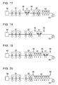
- Fig. 13 shows the cooling device according to the present invention for cooling only the upper side of the strip.
- the number of the headers required for cooling is preliminarily estimated, and the injection is performed from the innermost cooling header.
- the temperature at the leading end of the strip is measured. If the temperature of the leading end of the strip is higher than the target temperature, the number of the cooling headers for injecting the coolant is increased.
- the coolant is injected sequentially in the order of the circled number as shown in Fig. 13 such that the header at the inner and downstream side is prioritized and the number of the headers at the upstream side becomes equal to that of the headers at the downstream side.
- the number of the cooling headers for injecting the coolant is reduced.
- the injection of the cooling header is sequentially stopped from the outer side. The injection is stopped from the header with the circled number in descending order.
- Fig. 14 shows the cooling device for cooling both the upper and the lower sides.
- the coolant is injected to the upper surface to hold the strip on the table roll to switch ON-OFF of the cooling header for injection such that the purging property and the cooling capability are stabilized while keeping the threading of the strip.
- the number of the headers required for cooling is preliminarily estimated, and the coolant is injected from the upper headers 21a and 21b at the innermost sides, and the lower side header.
- the temperature of the leading end of the strip passing through the cooling device is measured.
- the number of the cooling headers for injection is increased.
- the coolant is injected in the order of the circled number as shown in Fig. 14 such that the headers at the inner side and the downstream side are prioritized, and the number of the headers for injection at the upstream side is substantially the same as that of the headers for injection at the downstream side.
- the coolant for the lower side is injected in the state where the coolant for the upper side impinges at substantially the same point where the coolant for the lower side impinges, and the coolant impinges against the upper surface.
- the header for injecting the coolant to the upper side is added, the header for injecting the coolant to the lower side is added as well.
- the aforementioned addition of the headers is repeatedly performed to increase the entire number of the headers for injection. Meanwhile, if the temperature of the leading end of the strip becomes lower than the target temperature in the course of the adjustment, the number of the coolant headers for injection is reduced. In such a case, the injection is stopped from the coolant header at the outer side sequentially. In other words, the injection is stopped from the header in descending order of the circled number as shown in Fig. 14 .
- the use of the excessively thin strip may make the threading performance of the leading end instable in the cooling device according to the present invention.
- the coolant serves as the resistance to lower the rate at the leading end of the strip.
- it is pushed from the rolling machine at the constant rate, which may cause the risk of sagging the plate, thus generating the loop.
- the number of the headers for injecting the coolant only at the leading end of the strip is reduced, the amount of the coolant is reduced or supply of the coolant is stopped such that the cooling is performed with a predetermined amount of coolant or the predetermined numbers of the headers after the passage of the leading end of the strip through the cooling device.
- the nozzle is provided with the check valve, or the header is provided with the discharge valve which is opened when stopping the injection of the coolant for immediately discharging the coolant inside the header.
- the structure for cooling the strip by the cooling device 51 according to the present invention provided at the output side of the finish rolling machine, and further by the existing cooling device 52 has been described.
- the structure having the cooling device 51b between the existing cooling devices 52a and 52a, or the structure having the cooling device 51c according to the present invention disposed downstream of the existing cooling device 52b may be employed.
- the cooling device 51a according to the present invention may be disposed at all the positions as described above including the case where the cooling device 51a according to the present invention is disposed between the finishing stand and the existing cooling device 52a.
- the structure for cooling only with the cooling device 51 according to the present invention may be employed.
- the cooling device 51 according to the present invention may be disposed at an arbitrary position on the line for manufacturing the hot strip, for example, at the position between the roughing stand 61 and the finishing stand 62 as shown in Fig. 17 .
- the cooling device 51 is disposed at the output side of the finishing stand 62 as shown in Figs. 18, 19 and 20 for manufacturing the hot strip.
- the slab with the thickness of 240 mm is heated to 1200°C in the heating furnace 60, rolled by the roughing stand 61 to the thickness of 35 mm, and further rolled by the finishing stand 62 at the temperature at the end of finishing of 850°C to the thickness of 3.2 mm. It is then cooled by the cooling device to 450°C so as to be coiled by the coiler 63.
- the cooling device 51 according to the present invention (cooling device 20 according to the first aspect, cooling device 40 according to the second aspect) is disposed as shown in Figs. 18 and 19 to cool the finished strip.
- the finished strip is cooled by the existing cooling device 52 without using the cooling device 51 according to the present invention.
- Example 1 the cooling device 51 of the present invention was disposed at the output side of the finishing stand 62 as shown in Fig. 18 for cooling the strip finished at 850°C to 450°C.
- the cooling device 20 was used as the cooling device 51 of the present invention, using 10 upper headers 21a and 21b (20 upper headers in total) each at the depression ⁇ of 45° in the conveying direction, and 20 spray cooling headers corresponding to the upper headers for cooling the lower side.
- the round type nozzles 22 in four rows were installed in the upper headers 21 in the strip conveying direction, and the injection rate of the rod-like flow was set to 8 m/s.
- the upper nozzle 22 was positioned at the height 1200 mm from the table roll.
- the coolant amount density was 3 m 3 /m 2 min for both the upper and the lower sides.
- the rolling rate was kept constant at 550 mpm, and the strip temperature before entering into the cooling device 51 was adjusted to be constant.
- the predetermined numbers of the headers for injecting the coolant were operated in the order from the inner side preferentially. The number of the headers for injecting the coolant was not changed while cooling the strip.
- Example 2 the cooling device 51 of the present invention was disposed at the output side of the finishing stand 62 as shown in Fig. 18 for cooling the strip finished at 850°C to 450°C.
- Example 2 was substantially the same as Example 1 except that the number of the headers for injecting the coolant was changed for correcting the difference between the temperature measured by the thermometer 65 disposed at the output side of the cooling device 51 while cooling the strip and the target temperature.
- Example 3 the existing cooling device 52 and the cooling device 51 of the present invention were disposed at the output side of the finishing stand 62.
- the strip finished at 850°C was cooled by the existing cooling device 52 to 600°C, and further cooled by the cooling device 51 to 450°C.
- the existing cooling device 52 employed the hair-pin laminar cooling for the upper side, and the spray cooling for the lower side having the coolant amount density set to 0.7 m 3 /m 2 min.
- the cooling device 20 was employed as the cooling device 51 of the present invention, having 10 upper headers 21a and 21b (20 upper headers in total) each at the depression ⁇ of 45° in the conveying direction.
- the lower side cooling was performed by 20 spray cooling headers corresponding to the upper headers.
- the round type nozzles 22 in four rows were installed in the upper headers 21 in the strip conveying direction, and the injection rate of the rod-like flow was set to 8 m/s.
- the upper nozzle 22 was positioned at the height 1200 mm from the table roll.
- the coolant amount density was 3 m 3 /m 2 min for both the upper and the lower sides.
- the rolling rate was kept constant at 550 mpm, and the strip temperature before entering into the cooling device 51 was adjusted to be constant.
- the predetermined numbers of the headers for injecting the coolant were operated from the inner side preferentially.
- the number of the headers for injecting the coolant was changed for correcting the difference between the temperature measured by the thermometer 65 disposed at the output side of the cooling device 51 while cooling the strip and the target temperature.
- Example 4 the cooling device 51 of the present invention was disposed at the output side of the finishing stand 62 as shown in Fig. 18 for cooling the strip finished at 850°C to 450°C.
- the cooling device 40 according to the second aspect including the shielding plate 26 was employed as the cooling device 51 of the present invention, having 10 upper headers 21a and 21b (20 upper headers in total) each at the depression ⁇ of 50° in the conveying direction.
- the lower side cooling was performed by 20 spray cooling headers corresponding to the upper headers.
- the round type nozzles 22 in the center of the width had the outward angle ⁇ set to 0 at the installation pitch of 100 mm in the width direction while gradually increasing the outward angle ⁇ towards the ends of the width at 10°.
- the round type nozzles 22 in four rows were installed in the upper headers 21 in the strip conveying direction, and the injection rate of the rod-like flow was set to 8 m/s.
- the upper nozzle 22 was positioned at the height 1200 mm from the table roll.
- the coolant amount density was 3 m 3 /m 2 min for both the upper and the lower sides.
- the rolling rate was kept constant at 550 mpm, and the strip temperature before entering into the cooling device 51 was adjusted to be constant.
- the predetermined numbers of the headers for injecting the coolant were operated in the order from the inner side preferentially.
- the number of the headers for injecting the coolant was changed for correcting the difference between the temperature measured by the thermometer 65 disposed at the output side of the cooling device 51 while cooling the strip and the target temperature.
- Example 5 the existing cooling device 52 and the cooling device 51 of the present invention 51 were disposed at the output side of the finishing stand 62 as shown in Fig. 19 .
- the strip finished at 850°C was cooled to 600°C by the existing cooling device 52, and further cooled to 450°C by the cooling device 51 according to the present invention.
- the existing cooling device 52 employed the hair-pin laminar cooling for the upper side and the spray cooling for the lower side with the coolant amount density of 0.7 m 3 /m 2 min.
- the cooling device 40 according to the second aspect including the shielding curtain 28 was employed as the cooling device 51 of the present invention, having 10 upper headers 21a and 21b (20 upper headers in total) each at the depression ⁇ of 50° in the conveying direction.
- the lower side cooling was performed by 20 spray cooling headers corresponding to the upper headers.
- the round type nozzles 22 in the center of the width had the outward angle ⁇ set to 0 at the installation pitch of 100 mm in the width direction while gradually increasing the outward angle ⁇ toward the ends of the width at 25°.
- the round type nozzles 22 in four rows were installed in the upper headers 21 in the strip conveying direction, and the injection rate of the rod-like flow was set to 8 m/s.
- the upper nozzle 22 was positioned at the height 1200 mm from the table roll.
- the coolant amount density was 3 m 3 /m 2 min for both the upper and the lower sides.
- the rolling rate wa.s kept constant at 550 mpm, and the strip temperature before entering into the cooling device 51 was adjusted to be constant.
- the predetermined numbers of the headers for injecting the coolant were operated in the order from the inner side preferentially.
- the number of the headers for injecting the coolant was changed for correcting the difference between the temperature measured by the thermometer 65 disposed at the output side of the cooling device 51 while cooling the strip and the target temperature.
- Comparative Example 1 the existing cooling device 52 was disposed at the output side of the finishing stand 62 for cooling the strip finished at 850°C to 450°C.
- the existing cooling device 52 employed the hair-pin laminar cooling for the upper side, and the spray cooling for the lower side with the coolant amount density of 0.7 m 3 /m 2 min.
- the distance from the cooling nozzle to the table roll was set to 1200 mm.
- the rolling rate was kept constant at 550 mpm, and the strip temperature before entering into the cooling device 51 was adjusted to be constant.
- the predetermined numbers of the headers for injecting the coolant were operated.
- the number of the headers for injecting the coolant was changed for correcting the difference between the temperature measured by the thermometer 65 disposed at the output side of the cooling device 51 while cooling the strip and the target temperature.
- the cooling device disclosed in Patent Document 1 was structured to inject the coolant from the slit nozzle units (gap of the slit nozzle: 5mm) arranged opposite the conveying direction, and to lift the slit nozzle unit so as to set the distance between the nozzle and the table roll to a predetermined value (100 mm).
- the coolant amount density was set to 3m 3 /m 2 min.
- the rolling rate was kept constant at 550 mpm, and the strip temperature before entering into the cooling device was adjusted to be constant.
- the predetermined numbers of the headers for injecting the coolant were operated.
- the number of the headers for injecting the coolant was changed for correcting the difference between the temperature measured by the thermometer 65 disposed at the output side of the cooling device while cooling the strip and the target temperature.
- the cooling device disclosed in Patent Document 2 is structured to allow the slit nozzle units (slit nozzle gap: 5 mm) oppositely arranged with respect to the conveying direction to inject the coolant, and has a partition plate above the nozzle.
- the distance between the nozzle and the table roll was set to 150 mm
- the distance between the partition plate and the table roll was set to 400 mm.
- the coolant amount density was set to 3 m 3 /m 2 min likewise the Examples 1 to 5.
- the rolling rate was kept constant at 550 mpm, and the strip temperature before entering into the cooling device was adjusted to be constant.
- the predetermined numbers of the headers for injecting the coolant were operated.
- the number of the headers for injecting the coolant was changed for correcting the difference between the temperature measured by the thermometer 65 disposed at the output side of the cooling device 51 while cooling the strip and the target temperature.
- the temperature of the cooled finished strip substantially corresponds to the tensile strength as the material property.
- the acceptable temperature difference after cooling was set to 50°C. If the temperature difference is larger than the acceptable value, variation in the material becomes too large to be shipped.
- Comparative Example 1 provided with the existing cooling device 52, the distance between the table roll and the cooling device was set to be as long as 1200 mm. Although the trouble of impingement of the hot strip against the cooling device did not occur, the temperature difference after cooling was as large as 120°C. The large variation of such property as strength was observed, thus failing to ship the resultant product. As the strip was conveyed to the coiler while having the coolant injected from the cooling device resided thereon for a long time, the portion with the residual coolant was only cooled. The error correction was conducted using the thermometer at the output side of the cooling device for solving the aforementioned problem. The local temperature unevenness was observed at a part of the strip. The feedback for changing the number of the headers for injecting the coolant was too late to fail to conduct the adjustment. As a result, the large temperature unevenness was kept unsolved.
- Comparative Example 2 provided with the oppositely arranged slit nozzles for injecting the coolant as disclosed in Patent Document 1, the hot strip jumped up to the height of approximately 200 to 300 mm while being finished and conveyed to the coiler to frequently cause such trouble as impingement against the cooling device. Meanwhile, the temperature difference with respect to the cooled hot strip without being impinged against the cooling nozzle was 40°C lower than the target acceptable temperature difference after the cooling at 50°C. The unevenness of such material as strength was small. In the case where the good threading performance was obtained, the slit nozzles were oppositely arranged for injection, and no residual coolant existed on the strip. The resultant temperature difference was relatively small, but larger than each temperature difference of Examples 1 to 5 as described later.
- Comparative Example 3 provided with the oppositely arranged slit nozzles for injecting the coolant as disclosed in Patent Document 2, the hot strip jumped up to the height of approximately 200 to 300 mm in the course of finishing and conveying to the coiler to frequently cause such trouble as impingement against the cooling device. Meanwhile, the temperature difference with respect to the cooled hot strip without being impinged against the coolant nozzle was within the range of the target acceptable temperature difference after the cooling at 50°C. The variation of such material as strength was small. In the case where the good threading performance was obtained, the slit nozzles were oppositely arranged for injection, and no residual coolant existed on the strip. The resultant temperature difference was relatively small, but larger than each temperature difference of Examples 1 to 5.
- Example 1 the distance between the table roll and the cooling device was set to be as long as 1200 mm.
- the trouble of impingement of the hot strip against the cooling device did not occur, and the temperature difference after cooling was as small as 15°C.
- the variation of such property as strength was hardly observed as the rod-like flows were injected from opposite directions for cooling while preventing the coolant from residing on the strip.
- Example 2 the distance between the table roll and the cooling device was set to be as long as 1200 mm likewise Example 1.
- the trouble of impingement of the hot strip against the cooling device did not occur, and the temperature difference after cooling was as small as 7°C which was lower compared with Example 1.
- the variation of such property as strength was hardly observed as the rod-like flows were injected from opposite directions for cooling while preventing the coolant from residing on the strip.
- the number of the headers for injecting the coolant was adjusted appropriately for correcting the error based on the temperature measured by the thermometer.
- Example 3 the distance between the table roll and the cooling device was set to be as long as 1200 mm.
- the trouble of impingement of the hot strip against the cooling device hardly occurred, and the temperature difference was 20°C which was substantially the same as that of Example 1.
- the temperature difference became slightly large owing to the residual coolant on the strip at the former cooling stage using the existing cooling device.
- the strip was immediately cooled using the cooling device of the present invention to shorten the duration for which the coolant resides.
- the number of the headers for injecting the coolant was changed to correct the difference based on the temperature measured by the thermometer. The resultant effects allowed the temperature difference to be substantially the same as that of Example 1.
- Example 4 the distance between the table roll and the cooling device was set to be as long as 1200 mm.
- the trouble of impingement of the hot strip against the cooling device did not occur, and the temperature difference after cooling was as small as 5°C.
- the variation of such property as strength was hardly observed because the strip was cooled by opposite injections of the rod-like flows while preventing the residual coolant from residing on the strip.
- Example 5 as the distance between the table roll and the cooling device was set to be as long as 1200 mm, the trouble of impingement of the hot strip against the cooling device did not occur.
- the temperature difference after cooling was as small as 13°C. The unevenness of such property as strength was hardly observed because the strip was cooled by opposite injections of the rod-like flows while preventing the residual coolant from residing on the strip.
- the temperature difference after cooling was observed better than the value of Example 1 because of the shielding curtain for appropriately shielding the scattering flow and change in the number of the headers for injecting the coolant for correcting the error based on the temperature measured by the thermometer appropriately.
- the temperature difference was slightly larger than those values of Examples 2 and 4 because of the residual coolant on the strip upon former cooling by the existing cooling device.
- the strip was immediately cooled by the cooling device of the present invention to substantially shorten the duration for which the coolant resided. As a result, the temperature difference may be made negligible.
- the use of the present invention for cooling the finished hot strip allows the coolant to be appropriately purged on the strip without impingement against the upper headers and upper nozzles and without causing the thermal deformation or clogging of the nozzle with the foreign substance. The possibility of uniform cooling was confirmed.
- the cooling device 51 of the present invention is disposed between the roughing stand 61 and the finishing stand 62 for manufacturing the hot strip as shown in Figs. 21 and 22 .
- the slab with the thickness of 240 mm is heated to 1200°C in a heating furnace 60, rolled by the roughing stand 61 to the thickness of 35 mm at the roughed temperature of 1100°C. It is cooled by the cooling device to 1000°C and further rolled by the finishing stand 62 to the thickness of 3.2 mm. It is then cooled by the cooling device to the predetermined temperature so as to be coiled by the coiler 63.
- cooling device 51 of the present invention (cooling device 20 according to the first aspect, cooling device 40 according to the second aspect) is disposed as shown in Fig. 21 to cool the finished strip.
- the finished strip was cooled by the existing cooling device 52 without using the cooling device 51 of the present invention.
- Example 6 the cooling device 51 of the present invention was disposed between the roughing stand 61 and the finishing stand 62 as shown in Fig. 21 for cooling the strip roughed at 1100°C to 1000°C.
- the cooling device 20 was used as the cooling device 51 of the present invention, using 10 upper headers 21a and 21b (20 upper headers in total) each at the depression ⁇ of 50° in the conveying direction, and 20 spray cooling headers corresponding to the upper headers for cooling the lower side.
- the round type nozzles 22 in four rows were installed in the upper headers 21 in the strip conveying direction, and the injection rate of the rod-like flow was set to 8 m/s.
- the upper nozzle 22 was positioned at the height 1200 mm from the table roll.
- the coolant amount density was 3m 3 /m 2 min for both the upper and the lower sides.
- the rolling rate was kept constant at 250 mpm, and the strip temperature before entering into the cooling device 51 was adjusted to be constant.
- the predetermined numbers of the headers for injecting the coolant were operated from the inner side preferentially. The number of the headers for injecting the coolant was not changed while cooling the strip.
- Example 7 the cooling device 51 of the present invention was disposed between the roughing stand 61 and the finishing stand 62 as shown in Fig. 21 for cooling the strip roughed at 1100°C to 1000°C.
- the cooling device 40 according to the second aspect including the shielding plate 26 was employed as the cooling device 51 of the present invention, having 10 upper headers 21a and 21b (20 upper headers in total) each at the depression ⁇ of 45° in the conveying direction.
- the lower side cooling was performed by 20 spray cooling headers corresponding to the upper headers.
- the round type nozzles 22 in four rows were installed in the upper headers 21 in the strip conveying direction, and the injection rate of the rod-like flow was set to 8 m/s.
- the upper nozzle 22 was positioned at the height 1200 mm from the table roll.
- the coolant amount density was 3 m 3 /m 2 min for both the upper and the lower sides.
- the rolling rate was kept constant at 250 mpm, and the strip temperature before entering into the cooling device 51 was adjusted to be constant.
- the predetermined numbers of the headers for injecting the coolant were operated from the inner side preferentially. The number of the headers for injecting the coolant was not changed while cooling the strip.
- Comparative Example 4 the existing cooling device 52 was disposed between the roughing stand 61 and the finishing stand 62 for cooling the strip roughed at 1100°C to 1000°C.
- the existing cooling device 52 employed the hair-pin laminar cooling for the upper side, and the spray cooling for the lower side with the coolant amount density of 0.7 m 3 /m 2 min.
- the distance from the cooling nozzle to the table roll was set to 1200 mm.
- the rolling rate was kept constant at 250 mpm, and the strip temperature before entering into the cooling device 52 was adjusted to be constant.
- the predetermined numbers of the headers for injecting the coolant were operated. The number of the headers for injecting the coolant was not changed while cooling the strip.
- the temperature at the input side of the finishing stand has to be set to 1000°C, and the temperature difference has to be set to be within 20°C for suppressing the increase in the finished strip temperature and generation of the surface flaw upon cooling subsequent to the roughing.
- Example 6 the distance between the table roll and the cooling device was set to be as long as 1200 mm. The trouble of impingement of the hot strip against the cooling device did not occur. The temperature difference at the input side of the finishing stand after cooling was as small as 17°C because the oppositely injected rod-like flows for cooling prevented the coolant from residing on the strip.
- Example 7 the distance between the table roll and the cooling device was set to be as long as 1200 mm. The trouble of impingement of the hot strip against the cooling device did not occur.
- the temperature difference at the input side of the finishing stand after cooling was as small as 7°C because the oppositely injected rod-like flows for cooling prevented the coolant from residing on the strip. The temperature difference was observed to be better than that of Example 6 as the shielding plate appropriately shielded the scattering flow.
- the present invention for cooling the roughed hot strip was used such that the coolant was appropriately purged on the strip without impingement against the upper headers and upper nozzles, and without causing the thermal deformation or clogging of the nozzle with the foreign substance. The possibility of uniform cooling was confirmed.
- the finished hot strip is cooled using the cooling device according to the present invention by coiling the finished hot strip using the coiler while accelerating the rate.
- Example 8 the cooling device 51 of the present invention was disposed at the output side of the finishing stand 62 as shown in Fig. 23 for cooling the hot strip coiled by the coiler 63 while being accelerated.
- the slab with the thickness of 240 mm was heated to 1200°C in the heating furnace 60, rolled by the roughing stand 61 to the thickness of 35 mm, and further rolled by the finishing stand 62 at the finishing temperature of 850°C to the thickness of 3.2 mm. It was then cooled by the cooling device 51 of the present invention to 450°C so as to be coiled by the coiler 63.
- the rolling rate (threading rate) upon coiling was 550 mpm.
- the acceleration started at 5 mpm/s
- the rolling rate (threading rate) at the trailing end of the strip was 660 mpm.
- the entire length of the strip was 600 m.
- the cooling device 20 was used as the cooling device 51 of the present invention, using 10 upper headers 21a and 21b (20 upper headers in total) each at the depression ⁇ of 45° in the conveying direction, and 20 spray cooling headers for cooling the lower side.
- the round type nozzles 22 in four rows were installed in the upper headers 21 in the strip conveying direction, and the injection rate of the rod-like flow was set to 8 m/s.
- the upper nozzle 22 was positioned at the height 1200 mm from the table roll.
- the coolant amount density was 3 m 3 /m 2 min for both the upper and the lower sides. This allows the upper and the lower sides to have the same cooling capability.
- the cooling device 51 according to the present invention was used for cooling the hot strip coiled by the coiler while being accelerated as described above.
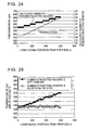
- the required number of the headers for injecting the coolant of the cooling device in accordance with the respective positions in the longitudinal direction of the strip was calculated based on the cooling rate of the cooling device according to the present invention and the time taken for the strip to pass through the cooling device while considering the acceleration of the hot strip (increase in the threading rate) at each of the positions in the longitudinal direction of the strip as shown in Fig. 24 .
- the required number of the headers for injection shown in Fig. 24 (30 to 36 headers) represents the total number of the upper and the lower headers.
- Each position information of the positions of the strip in the longitudinal direction was tracked, and the coolant was injected while adjusting (increasing) the number of the headers for injecting the coolant so as to establish the calculated required number at each passage of the positions of the hot strip through the cooling device.
- the number of the headers for injecting the coolant was adjusted (increased or decreased) for correcting the difference between the temperature measured at the output side of the cooling device and the target temperature.
- the number of the cooling headers was adjusted by switching ON-OFF of the coolant from the inner header preferentially in the order of the circled number as shown in Fig. 14 .
- Fig. 25 shows the comparison between the case for cooling while keeping the number of the headers constant and the case for cooling while adjusting the number of the headers for injecting the coolant as in Example 8.
- Application of the present invention for cooling the finished strip allows the temperature to be accurately controlled to the value equal to or lower than 500°C which has conventionally failed to achieve the accurate temperature value at the end of cooling.
- the material variation of the hot strip at the coiling temperature equal to or lower than 500°C with large variation in the strength or ductility is reduced to allow the material control in the narrow range.
- the temperature adjustment during manufacturing of the hot strip for example, cooling on the transition from the roughing to finishing may be conducted with higher accuracy, thus reducing the yielding and providing the stabilized quality.
Landscapes
- Engineering & Computer Science (AREA)
- Chemical & Material Sciences (AREA)
- Mechanical Engineering (AREA)
- Crystallography & Structural Chemistry (AREA)
- Thermal Sciences (AREA)
- Physics & Mathematics (AREA)
- Materials Engineering (AREA)
- Metallurgy (AREA)
- Organic Chemistry (AREA)
- General Engineering & Computer Science (AREA)
- Heat Treatment Of Strip Materials And Filament Materials (AREA)
- Heat Treatments In General, Especially Conveying And Cooling (AREA)
- Metal Rolling (AREA)
Priority Applications (1)
| Application Number | Priority Date | Filing Date | Title |
|---|---|---|---|
| PL08703516T PL2116313T3 (pl) | 2007-02-26 | 2008-01-15 | Urządzenie oraz sposób chłodzenia stalowej taśmy walcowanej na gorąco |
Applications Claiming Priority (2)
| Application Number | Priority Date | Filing Date | Title |
|---|---|---|---|
| JP2007044868A JP4449991B2 (ja) | 2007-02-26 | 2007-02-26 | 熱延鋼帯の冷却装置及び方法 |
| PCT/JP2008/050666 WO2008117552A1 (ja) | 2007-02-26 | 2008-01-15 | 熱延鋼帯の冷却装置及び方法 |
Publications (3)
| Publication Number | Publication Date |
|---|---|
| EP2116313A1 EP2116313A1 (en) | 2009-11-11 |
| EP2116313A4 EP2116313A4 (en) | 2013-04-17 |
| EP2116313B1 true EP2116313B1 (en) | 2014-03-12 |
Family
ID=39783960
Family Applications (1)
| Application Number | Title | Priority Date | Filing Date |
|---|---|---|---|
| EP08703516.8A Active EP2116313B1 (en) | 2007-02-26 | 2008-01-15 | Device and method for cooling hot-rolled steel strip |
Country Status (10)
| Country | Link |
|---|---|
| US (1) | US8404062B2 (pl) |
| EP (1) | EP2116313B1 (pl) |
| JP (1) | JP4449991B2 (pl) |
| KR (1) | KR100976758B1 (pl) |
| CN (1) | CN101622083B (pl) |
| AU (1) | AU2008230641B2 (pl) |
| CA (1) | CA2679695C (pl) |
| PL (1) | PL2116313T3 (pl) |
| TW (1) | TW200902178A (pl) |
| WO (1) | WO2008117552A1 (pl) |
Families Citing this family (37)
| Publication number | Priority date | Publication date | Assignee | Title |
|---|---|---|---|---|
| JP5577655B2 (ja) * | 2009-09-04 | 2014-08-27 | Jfeスチール株式会社 | 熱延鋼板の冷却設備および冷却方法 |
| IN2012DN00945A (pl) | 2009-12-16 | 2015-04-10 | Nippon Steel & Sumitomo Metal Corp | |
| JP5685861B2 (ja) * | 2010-09-02 | 2015-03-18 | Jfeスチール株式会社 | 熱鋼板の水切り装置、水切り方法および冷却設備 |
| CN102228910A (zh) * | 2011-07-19 | 2011-11-02 | 东北大学 | 一种用于热轧带钢生产线的轧后超快速冷却系统 |
| CN102380597B (zh) * | 2011-10-28 | 2014-03-19 | 中冶赛迪工程技术股份有限公司 | 板坯连铸二冷喷水宽度控制的方法 |
| KR101376565B1 (ko) * | 2011-12-15 | 2014-04-02 | (주)포스코 | 연속 소둔라인 급냉대의 스트립 온도제어 방법 및 장치 |
| CN102626719A (zh) * | 2012-04-24 | 2012-08-08 | 青岛钢铁控股集团有限责任公司 | 线材生产用控冷装置及线材生产设备 |
| TWI524951B (zh) * | 2012-06-08 | 2016-03-11 | 新日鐵住金股份有限公司 | 熱軋鋼板用冷卻水之水擋裝置及水擋方法 |
| JP5825250B2 (ja) * | 2012-12-25 | 2015-12-02 | Jfeスチール株式会社 | 熱延鋼帯の冷却方法および冷却装置 |
| EP2792428A1 (de) * | 2013-04-15 | 2014-10-22 | Siemens VAI Metals Technologies GmbH | Kühleinrichtung mit breitenabhängiger Kühlwirkung |
| JP5999265B2 (ja) * | 2013-08-02 | 2016-09-28 | 東芝三菱電機産業システム株式会社 | 省エネルギー操業リコメンドシステム |
| WO2015064167A1 (ja) * | 2013-10-29 | 2015-05-07 | 新日鐵住金株式会社 | 線材冷却装置及び線材冷却方法 |
| CN103752626B (zh) * | 2013-12-30 | 2015-11-25 | 秦皇岛首秦金属材料有限公司 | 利用acc半自动水冷提高钢板表面质量的生产方法 |
| PL3190474T3 (pl) * | 2014-09-01 | 2021-09-13 | Scientific And Manufacturing Enterprise "Tomsk Electronic Company" Ltd. | Urządzenie do monitorowania natężenia przepływu i równomierności rozkładu cieczy w wielokanałowym układzie hydraulicznym |
| CN105618492B (zh) * | 2014-11-28 | 2018-08-10 | 宝山钢铁股份有限公司 | 一种用于钢板在线固溶的轧后快速冷却系统 |
| JP6233613B2 (ja) * | 2016-01-26 | 2017-11-22 | Jfeスチール株式会社 | 熱延鋼帯の製造設備列および熱延鋼帯の製造方法 |
| DE102016102093B3 (de) * | 2016-02-05 | 2017-06-14 | Bwg Bergwerk- Und Walzwerk-Maschinenbau Gmbh | Durchlaufkühlvorrichtung und Verfahren zum Abkühlen eines Metallbandes |
| CN105695697B (zh) * | 2016-04-06 | 2018-07-13 | 肇庆科达机械制造有限公司 | 一种铝型材在线淬火装置及方法 |
| EP3251764B1 (de) * | 2016-05-31 | 2019-07-03 | Primetals Technologies Austria GmbH | Verfahren und vorrichtung zur stabilisierung einer bewegung eines gewalzten metallischen bandes auf einem rollgang |
| DE102016110677B4 (de) * | 2016-06-09 | 2018-07-12 | Ebner Industrieofenbau Gmbh | Temperiervorrichtung für Bauteile |
| BR112018074428B1 (pt) * | 2016-08-09 | 2023-04-18 | Toshiba Mitsubishi-Electric Industrial Systems Corporation | Sistema de controle de temperatura do lado de saída de laminador |
| DE102016223131A1 (de) * | 2016-09-06 | 2018-03-08 | Sms Group Gmbh | Vorrichtung und Verfahren zum Aufbringen eines flüssigen Mediums auf eine Walze und/oder auf ein Walzgut und/oder zum Entfernen des flüssigen Mediums |
| CN106269932A (zh) * | 2016-10-25 | 2017-01-04 | 东北大学 | 一种热轧无缝钢管在线控制冷却设备 |
| CN106311763B (zh) * | 2016-10-25 | 2019-04-26 | 东北大学 | 一种热轧无缝钢管控制冷却用环形射流冷却装置 |
| EP3385008A1 (de) * | 2017-04-04 | 2018-10-10 | Primetals Technologies Austria GmbH | Entzunderungsvorrichtung und verfahren zum chemischen entzundern eines metallbandes |
| TWI690375B (zh) * | 2017-04-17 | 2020-04-11 | 日商日本製鐵股份有限公司 | 熱軋鋼板之冷卻裝置以及熱軋鋼板之冷卻方法 |
| WO2019097713A1 (ja) * | 2017-11-20 | 2019-05-23 | Primetals Technologies Japan株式会社 | 金属板の冷却装置及び金属板の連続熱処理設備 |
| WO2019160574A1 (en) * | 2018-02-17 | 2019-08-22 | Primetals Technologies USA LLC | Cooling system |
| DE102018205685A1 (de) * | 2018-04-13 | 2019-10-17 | Sms Group Gmbh | Kühleinrichtung und Verfahren zu deren Betrieb |
| DE102018109579A1 (de) * | 2018-04-20 | 2019-10-24 | Schwartz Gmbh | Temperiervorrichtung zur partiellen Kühlung eines Bauteils |
| WO2020059577A1 (ja) * | 2018-09-19 | 2020-03-26 | 日本製鉄株式会社 | 熱延鋼板の冷却装置および熱延鋼板の冷却方法 |
| EP3763836B1 (en) * | 2019-07-11 | 2023-06-07 | John Cockerill S.A. | Cooling device for blowing gas onto a surface of a traveling strip |
| WO2021065583A1 (ja) * | 2019-09-30 | 2021-04-08 | Jfeスチール株式会社 | 金属帯急冷装置及び金属帯急冷方法並びに金属帯製品の製造方法 |
| CN111664615B (zh) * | 2020-06-16 | 2022-02-01 | 安徽伟辰钢结构有限公司 | 一种h型钢生产线 |
| CN114345954A (zh) * | 2021-12-13 | 2022-04-15 | 首钢京唐钢铁联合有限责任公司 | 一种带钢冷却控制方法、装置以及设备 |
| CN114618895B (zh) * | 2022-04-11 | 2022-11-08 | 福建三宝特钢有限公司 | 基于动态调节的热轧带轧制系统 |
| CN116144888B (zh) * | 2023-02-01 | 2024-02-20 | 北京科技大学 | 基于横纵温差的双相钢板带均质化挂卷及控冷调质方法 |
Family Cites Families (15)
| Publication number | Priority date | Publication date | Assignee | Title |
|---|---|---|---|---|
| JPS55106615A (en) | 1979-02-09 | 1980-08-15 | Kawasaki Steel Corp | Rolling method with controlled rolling |
| JPH0238283B2 (ja) | 1983-02-09 | 1990-08-29 | Mitsubishi Heavy Ind Ltd | Kohanreikyakusochi |
| JPS62260022A (ja) | 1986-05-01 | 1987-11-12 | Ishikawajima Harima Heavy Ind Co Ltd | 鋼板の冷却装置 |
| CN1049303A (zh) * | 1989-09-15 | 1991-02-20 | 沃洛格达综合技术学院 | 冷却热轧板材的方法 |
| JPH06190419A (ja) * | 1992-12-24 | 1994-07-12 | Kawasaki Steel Corp | ストリップの冷却方法 |
| KR100260016B1 (ko) * | 1996-05-23 | 2000-06-15 | 아사무라 타카싯 | 연속식강대 열처리공정에 있어서 강대의 폭방향 균일 냉각장치 |
| JP3397072B2 (ja) * | 1997-03-13 | 2003-04-14 | 住友金属工業株式会社 | 鋼板の冷却装置及び方法 |
| JP2001286925A (ja) | 2000-04-10 | 2001-10-16 | Sumitomo Metal Ind Ltd | 鋼板の水冷装置とその水冷方法 |
| JP2003191005A (ja) | 2001-12-25 | 2003-07-08 | Jfe Engineering Kk | 熱延鋼帯の冷却方法およびその製造方法 |
| JP2005059038A (ja) | 2003-08-08 | 2005-03-10 | Sumitomo Metal Ind Ltd | 熱延鋼板の仕上げ圧延設備および熱延鋼板の製造方法 |
| JP4876781B2 (ja) | 2005-08-30 | 2012-02-15 | Jfeスチール株式会社 | 鋼板の冷却設備および冷却方法 |
| JP4876783B2 (ja) | 2005-08-30 | 2012-02-15 | Jfeスチール株式会社 | 鋼板の冷却設備および冷却方法 |
| EP1935522B1 (en) | 2005-08-30 | 2015-11-18 | JFE Steel Corporation | Reversing rolling mill with cooling facility and corresponding method of cooling a steel plate or sheet |
| JP4876782B2 (ja) | 2005-08-30 | 2012-02-15 | Jfeスチール株式会社 | 鋼板の熱間圧延設備および熱間圧延方法 |
| JP4779749B2 (ja) | 2006-03-28 | 2011-09-28 | Jfeスチール株式会社 | 鋼板の冷却方法および冷却設備 |
-
2007
- 2007-02-26 JP JP2007044868A patent/JP4449991B2/ja active Active
-
2008
- 2008-01-15 CA CA2679695A patent/CA2679695C/en active Active
- 2008-01-15 AU AU2008230641A patent/AU2008230641B2/en active Active
- 2008-01-15 WO PCT/JP2008/050666 patent/WO2008117552A1/ja active Application Filing
- 2008-01-15 KR KR1020097016525A patent/KR100976758B1/ko active IP Right Grant
- 2008-01-15 CN CN200880006160XA patent/CN101622083B/zh active Active
- 2008-01-15 EP EP08703516.8A patent/EP2116313B1/en active Active
- 2008-01-15 US US12/449,672 patent/US8404062B2/en active Active
- 2008-01-15 PL PL08703516T patent/PL2116313T3/pl unknown
- 2008-01-30 TW TW097103420A patent/TW200902178A/zh unknown
Also Published As
| Publication number | Publication date |
|---|---|
| CN101622083A (zh) | 2010-01-06 |
| TW200902178A (en) | 2009-01-16 |
| US8404062B2 (en) | 2013-03-26 |
| AU2008230641A1 (en) | 2008-10-02 |
| PL2116313T3 (pl) | 2014-08-29 |
| AU2008230641B2 (en) | 2012-01-19 |
| CA2679695C (en) | 2011-05-03 |
| EP2116313A1 (en) | 2009-11-11 |
| CA2679695A1 (en) | 2008-10-02 |
| KR100976758B1 (ko) | 2010-08-18 |
| TWI329042B (pl) | 2010-08-21 |
| JP2008207200A (ja) | 2008-09-11 |
| KR20090101369A (ko) | 2009-09-25 |
| EP2116313A4 (en) | 2013-04-17 |
| WO2008117552A1 (ja) | 2008-10-02 |
| CN101622083B (zh) | 2012-08-08 |
| JP4449991B2 (ja) | 2010-04-14 |
| US20100024505A1 (en) | 2010-02-04 |
Similar Documents
| Publication | Publication Date | Title |
|---|---|---|
| EP2116313B1 (en) | Device and method for cooling hot-rolled steel strip | |
| EP1935522B1 (en) | Reversing rolling mill with cooling facility and corresponding method of cooling a steel plate or sheet | |
| KR101266736B1 (ko) | 강판의 냉각 장치 및 강판의 냉각 방법 | |
| EP1944099B1 (en) | Cooling method of steel plate | |
| EP1925373B1 (en) | Method of cooling steel sheet | |
| JP4586682B2 (ja) | 鋼板の熱間圧延設備および熱間圧延方法 | |
| JP4779749B2 (ja) | 鋼板の冷却方法および冷却設備 | |
| JP4876782B2 (ja) | 鋼板の熱間圧延設備および熱間圧延方法 | |
| EP3603833B1 (en) | Device and method for cooling hot-rolled steel sheet | |
| WO2007037095A1 (ja) | 鋼板の冷却設備および製造方法 | |
| JP4853224B2 (ja) | 鋼板の冷却設備および冷却方法 | |
| JP6569843B1 (ja) | 厚鋼板の冷却装置および冷却方法ならびに厚鋼板の製造設備および製造方法 | |
| EP2979770B1 (en) | Thick steel plate manufacturing device and manufacturing method | |
| KR20190042723A (ko) | 열연 강판의 냉각 장치 및 냉각 방법 | |
| JP4337157B2 (ja) | 鋼板の冷却方法およびその装置 | |
| JP4876783B2 (ja) | 鋼板の冷却設備および冷却方法 | |
| JP4682669B2 (ja) | H形鋼の冷却設備及び冷却方法 | |
| WO2018056164A1 (ja) | 熱延鋼板の冷却装置及び冷却方法 | |
| JPH06339721A (ja) | H形鋼の冷却方法および冷却装置 | |
| JP2002282928A (ja) | 板状被冷却材の冷却装置及び冷却方法 |
Legal Events
| Date | Code | Title | Description |
|---|---|---|---|
| PUAI | Public reference made under article 153(3) epc to a published international application that has entered the european phase |
Free format text: ORIGINAL CODE: 0009012 |
|
| 17P | Request for examination filed |
Effective date: 20090825 |
|
| AK | Designated contracting states |
Kind code of ref document: A1 Designated state(s): AT BE BG CH CY CZ DE DK EE ES FI FR GB GR HR HU IE IS IT LI LT LU LV MC MT NL NO PL PT RO SE SI SK TR |
|
| DAX | Request for extension of the european patent (deleted) | ||
| A4 | Supplementary search report drawn up and despatched |
Effective date: 20130315 |
|
| RIC1 | Information provided on ipc code assigned before grant |
Ipc: C21D 1/667 20060101ALI20130311BHEP Ipc: B21B 45/02 20060101AFI20130311BHEP |
|
| GRAP | Despatch of communication of intention to grant a patent |
Free format text: ORIGINAL CODE: EPIDOSNIGR1 |
|
| RIC1 | Information provided on ipc code assigned before grant |
Ipc: B21B 45/02 20060101AFI20130820BHEP Ipc: C21D 1/667 20060101ALI20130820BHEP |
|
| INTG | Intention to grant announced |
Effective date: 20130926 |
|
| GRAS | Grant fee paid |
Free format text: ORIGINAL CODE: EPIDOSNIGR3 |
|
| GRAA | (expected) grant |
Free format text: ORIGINAL CODE: 0009210 |
|
| AK | Designated contracting states |
Kind code of ref document: B1 Designated state(s): AT BE BG CH CY CZ DE DK EE ES FI FR GB GR HR HU IE IS IT LI LT LU LV MC MT NL NO PL PT RO SE SI SK TR |
|
| REG | Reference to a national code |
Ref country code: GB Ref legal event code: FG4D |
|
| REG | Reference to a national code |
Ref country code: CH Ref legal event code: EP |
|
| REG | Reference to a national code |
Ref country code: AT Ref legal event code: REF Ref document number: 655884 Country of ref document: AT Kind code of ref document: T Effective date: 20140315 |
|
| REG | Reference to a national code |
Ref country code: IE Ref legal event code: FG4D |
|
| REG | Reference to a national code |
Ref country code: DE Ref legal event code: R096 Ref document number: 602008030784 Country of ref document: DE Effective date: 20140424 |
|
| REG | Reference to a national code |
Ref country code: SE Ref legal event code: TRGR |
|
| REG | Reference to a national code |
Ref country code: NL Ref legal event code: VDEP Effective date: 20140312 |
|
| PG25 | Lapsed in a contracting state [announced via postgrant information from national office to epo] |
Ref country code: LT Free format text: LAPSE BECAUSE OF FAILURE TO SUBMIT A TRANSLATION OF THE DESCRIPTION OR TO PAY THE FEE WITHIN THE PRESCRIBED TIME-LIMIT Effective date: 20140312 Ref country code: NO Free format text: LAPSE BECAUSE OF FAILURE TO SUBMIT A TRANSLATION OF THE DESCRIPTION OR TO PAY THE FEE WITHIN THE PRESCRIBED TIME-LIMIT Effective date: 20140612 |
|
| REG | Reference to a national code |
Ref country code: LT Ref legal event code: MG4D |
|
| PG25 | Lapsed in a contracting state [announced via postgrant information from national office to epo] |
Ref country code: CY Free format text: LAPSE BECAUSE OF FAILURE TO SUBMIT A TRANSLATION OF THE DESCRIPTION OR TO PAY THE FEE WITHIN THE PRESCRIBED TIME-LIMIT Effective date: 20140312 Ref country code: FI Free format text: LAPSE BECAUSE OF FAILURE TO SUBMIT A TRANSLATION OF THE DESCRIPTION OR TO PAY THE FEE WITHIN THE PRESCRIBED TIME-LIMIT Effective date: 20140312 |
|
| REG | Reference to a national code |
Ref country code: PL Ref legal event code: T3 |
|
| PG25 | Lapsed in a contracting state [announced via postgrant information from national office to epo] |
Ref country code: HR Free format text: LAPSE BECAUSE OF FAILURE TO SUBMIT A TRANSLATION OF THE DESCRIPTION OR TO PAY THE FEE WITHIN THE PRESCRIBED TIME-LIMIT Effective date: 20140312 Ref country code: LV Free format text: LAPSE BECAUSE OF FAILURE TO SUBMIT A TRANSLATION OF THE DESCRIPTION OR TO PAY THE FEE WITHIN THE PRESCRIBED TIME-LIMIT Effective date: 20140312 |
|
| PG25 | Lapsed in a contracting state [announced via postgrant information from national office to epo] |
Ref country code: CZ Free format text: LAPSE BECAUSE OF FAILURE TO SUBMIT A TRANSLATION OF THE DESCRIPTION OR TO PAY THE FEE WITHIN THE PRESCRIBED TIME-LIMIT Effective date: 20140312 Ref country code: IS Free format text: LAPSE BECAUSE OF FAILURE TO SUBMIT A TRANSLATION OF THE DESCRIPTION OR TO PAY THE FEE WITHIN THE PRESCRIBED TIME-LIMIT Effective date: 20140712 Ref country code: RO Free format text: LAPSE BECAUSE OF FAILURE TO SUBMIT A TRANSLATION OF THE DESCRIPTION OR TO PAY THE FEE WITHIN THE PRESCRIBED TIME-LIMIT Effective date: 20140312 Ref country code: BE Free format text: LAPSE BECAUSE OF FAILURE TO SUBMIT A TRANSLATION OF THE DESCRIPTION OR TO PAY THE FEE WITHIN THE PRESCRIBED TIME-LIMIT Effective date: 20140312 Ref country code: EE Free format text: LAPSE BECAUSE OF FAILURE TO SUBMIT A TRANSLATION OF THE DESCRIPTION OR TO PAY THE FEE WITHIN THE PRESCRIBED TIME-LIMIT Effective date: 20140312 Ref country code: BG Free format text: LAPSE BECAUSE OF FAILURE TO SUBMIT A TRANSLATION OF THE DESCRIPTION OR TO PAY THE FEE WITHIN THE PRESCRIBED TIME-LIMIT Effective date: 20140612 Ref country code: NL Free format text: LAPSE BECAUSE OF FAILURE TO SUBMIT A TRANSLATION OF THE DESCRIPTION OR TO PAY THE FEE WITHIN THE PRESCRIBED TIME-LIMIT Effective date: 20140312 |
|
| PG25 | Lapsed in a contracting state [announced via postgrant information from national office to epo] |
Ref country code: ES Free format text: LAPSE BECAUSE OF FAILURE TO SUBMIT A TRANSLATION OF THE DESCRIPTION OR TO PAY THE FEE WITHIN THE PRESCRIBED TIME-LIMIT Effective date: 20140312 Ref country code: SK Free format text: LAPSE BECAUSE OF FAILURE TO SUBMIT A TRANSLATION OF THE DESCRIPTION OR TO PAY THE FEE WITHIN THE PRESCRIBED TIME-LIMIT Effective date: 20140312 |
|
| REG | Reference to a national code |
Ref country code: DE Ref legal event code: R026 Ref document number: 602008030784 Country of ref document: DE |
|
| PLBI | Opposition filed |
Free format text: ORIGINAL CODE: 0009260 |
|
| PG25 | Lapsed in a contracting state [announced via postgrant information from national office to epo] |
Ref country code: PT Free format text: LAPSE BECAUSE OF FAILURE TO SUBMIT A TRANSLATION OF THE DESCRIPTION OR TO PAY THE FEE WITHIN THE PRESCRIBED TIME-LIMIT Effective date: 20140714 |
|
| PLAX | Notice of opposition and request to file observation + time limit sent |
Free format text: ORIGINAL CODE: EPIDOSNOBS2 |
|
| 26 | Opposition filed |
Opponent name: SMS SIEMAG AG Effective date: 20141212 |
|
| PG25 | Lapsed in a contracting state [announced via postgrant information from national office to epo] |
Ref country code: DK Free format text: LAPSE BECAUSE OF FAILURE TO SUBMIT A TRANSLATION OF THE DESCRIPTION OR TO PAY THE FEE WITHIN THE PRESCRIBED TIME-LIMIT Effective date: 20140312 |
|
| REG | Reference to a national code |
Ref country code: DE Ref legal event code: R026 Ref document number: 602008030784 Country of ref document: DE Effective date: 20141212 |
|
| PLBB | Reply of patent proprietor to notice(s) of opposition received |
Free format text: ORIGINAL CODE: EPIDOSNOBS3 |
|
| PG25 | Lapsed in a contracting state [announced via postgrant information from national office to epo] |
Ref country code: SI Free format text: LAPSE BECAUSE OF FAILURE TO SUBMIT A TRANSLATION OF THE DESCRIPTION OR TO PAY THE FEE WITHIN THE PRESCRIBED TIME-LIMIT Effective date: 20140312 |
|
| REG | Reference to a national code |
Ref country code: CH Ref legal event code: PL |
|
| PG25 | Lapsed in a contracting state [announced via postgrant information from national office to epo] |
Ref country code: MC Free format text: LAPSE BECAUSE OF FAILURE TO SUBMIT A TRANSLATION OF THE DESCRIPTION OR TO PAY THE FEE WITHIN THE PRESCRIBED TIME-LIMIT Effective date: 20140312 |
|
| PG25 | Lapsed in a contracting state [announced via postgrant information from national office to epo] |
Ref country code: LI Free format text: LAPSE BECAUSE OF NON-PAYMENT OF DUE FEES Effective date: 20150131 Ref country code: CH Free format text: LAPSE BECAUSE OF NON-PAYMENT OF DUE FEES Effective date: 20150131 |
|
| REG | Reference to a national code |
Ref country code: IE Ref legal event code: MM4A |
|
| REG | Reference to a national code |
Ref country code: FR Ref legal event code: PLFP Year of fee payment: 9 |
|
| PG25 | Lapsed in a contracting state [announced via postgrant information from national office to epo] |
Ref country code: IE Free format text: LAPSE BECAUSE OF NON-PAYMENT OF DUE FEES Effective date: 20150115 |
|
| PG25 | Lapsed in a contracting state [announced via postgrant information from national office to epo] |
Ref country code: GR Free format text: LAPSE BECAUSE OF FAILURE TO SUBMIT A TRANSLATION OF THE DESCRIPTION OR TO PAY THE FEE WITHIN THE PRESCRIBED TIME-LIMIT Effective date: 20140613 |
|
| REG | Reference to a national code |
Ref country code: DE Ref legal event code: R100 Ref document number: 602008030784 Country of ref document: DE |
|
| REG | Reference to a national code |
Ref country code: FR Ref legal event code: PLFP Year of fee payment: 10 |
|
| PLCK | Communication despatched that opposition was rejected |
Free format text: ORIGINAL CODE: EPIDOSNREJ1 |
|
| PG25 | Lapsed in a contracting state [announced via postgrant information from national office to epo] |
Ref country code: MT Free format text: LAPSE BECAUSE OF FAILURE TO SUBMIT A TRANSLATION OF THE DESCRIPTION OR TO PAY THE FEE WITHIN THE PRESCRIBED TIME-LIMIT Effective date: 20140312 |
|
| PLBN | Opposition rejected |
Free format text: ORIGINAL CODE: 0009273 |
|
| STAA | Information on the status of an ep patent application or granted ep patent |
Free format text: STATUS: OPPOSITION REJECTED |
|
| 27O | Opposition rejected |
Effective date: 20161207 |
|
| PG25 | Lapsed in a contracting state [announced via postgrant information from national office to epo] |
Ref country code: HU Free format text: LAPSE BECAUSE OF FAILURE TO SUBMIT A TRANSLATION OF THE DESCRIPTION OR TO PAY THE FEE WITHIN THE PRESCRIBED TIME-LIMIT; INVALID AB INITIO Effective date: 20080115 |
|
| PG25 | Lapsed in a contracting state [announced via postgrant information from national office to epo] |
Ref country code: TR Free format text: LAPSE BECAUSE OF FAILURE TO SUBMIT A TRANSLATION OF THE DESCRIPTION OR TO PAY THE FEE WITHIN THE PRESCRIBED TIME-LIMIT Effective date: 20140312 |
|
| REG | Reference to a national code |
Ref country code: FR Ref legal event code: PLFP Year of fee payment: 11 |
|
| PGFP | Annual fee paid to national office [announced via postgrant information from national office to epo] |
Ref country code: IT Payment date: 20221213 Year of fee payment: 16 |
|
| P01 | Opt-out of the competence of the unified patent court (upc) registered |
Effective date: 20230512 |
|
| PGFP | Annual fee paid to national office [announced via postgrant information from national office to epo] |
Ref country code: GB Payment date: 20231130 Year of fee payment: 17 |
|
| PGFP | Annual fee paid to national office [announced via postgrant information from national office to epo] |
Ref country code: SE Payment date: 20231127 Year of fee payment: 17 Ref country code: FR Payment date: 20231212 Year of fee payment: 17 |
|
| PGFP | Annual fee paid to national office [announced via postgrant information from national office to epo] |
Ref country code: PL Payment date: 20231128 Year of fee payment: 17 |
|
| PGFP | Annual fee paid to national office [announced via postgrant information from national office to epo] |
Ref country code: LU Payment date: 20240112 Year of fee payment: 17 |
|
| PGFP | Annual fee paid to national office [announced via postgrant information from national office to epo] |
Ref country code: AT Payment date: 20231227 Year of fee payment: 17 |
|
| PGFP | Annual fee paid to national office [announced via postgrant information from national office to epo] |
Ref country code: DE Payment date: 20231128 Year of fee payment: 17 |