EP2116156B1 - Verstellbare Kissenvorrichtung - Google Patents
Verstellbare Kissenvorrichtung Download PDFInfo
- Publication number
- EP2116156B1 EP2116156B1 EP09159083A EP09159083A EP2116156B1 EP 2116156 B1 EP2116156 B1 EP 2116156B1 EP 09159083 A EP09159083 A EP 09159083A EP 09159083 A EP09159083 A EP 09159083A EP 2116156 B1 EP2116156 B1 EP 2116156B1
- Authority
- EP
- European Patent Office
- Prior art keywords
- pillow
- supporting
- base
- bodies
- unit
- Prior art date
- Legal status (The legal status is an assumption and is not a legal conclusion. Google has not performed a legal analysis and makes no representation as to the accuracy of the status listed.)
- Ceased
Links
- 230000000295 complement effect Effects 0.000 description 1
- 230000001419 dependent effect Effects 0.000 description 1
- 239000013013 elastic material Substances 0.000 description 1
- 239000007788 liquid Substances 0.000 description 1
Images


Classifications
-
- A—HUMAN NECESSITIES
- A47—FURNITURE; DOMESTIC ARTICLES OR APPLIANCES; COFFEE MILLS; SPICE MILLS; SUCTION CLEANERS IN GENERAL
- A47G—HOUSEHOLD OR TABLE EQUIPMENT
- A47G9/00—Bed-covers; Counterpanes; Travelling rugs; Sleeping rugs; Sleeping bags; Pillows
- A47G9/10—Pillows
- A47G9/1009—Rigid frame constructions
-
- A—HUMAN NECESSITIES
- A47—FURNITURE; DOMESTIC ARTICLES OR APPLIANCES; COFFEE MILLS; SPICE MILLS; SUCTION CLEANERS IN GENERAL
- A47G—HOUSEHOLD OR TABLE EQUIPMENT
- A47G9/00—Bed-covers; Counterpanes; Travelling rugs; Sleeping rugs; Sleeping bags; Pillows
- A47G9/10—Pillows
Definitions
- the invention relates to a pillow, more particularly to an adjustable pillow device.
- a conventional pillow includes a hollow body that is configured with a plurality of chambers, each of which is received with a plurality of inflatable air bags therein and is filled with liquid therein. Hardness and thickness of the conventional pillow can be adjusted through change of amounts of air in the air bags. However, shapes of the air bags are not fixed, and the air bags cannot be effectively positioned in the chambers during use. Therefore, the conventional pillow cannot provide stable support. Furthermore, frequent change of the amounts of air in the air bags is inconvenient during use.
- Figure 1 illustrates another conventional pillow 2 that includes a plurality of base pads 21, and a top pad 22 disposed on the base pads 21.
- the base pads 21 and the top pad 22 are made of an elastic material.
- the top pad 22 has a convex portion 221 and a flat portion 222 for supporting respectively the neck and head of a human body thereon.
- a height difference between the flat portion 222 and the convex portion 221 is fixed. Therefore, the conventional pillow 2 cannot accommodate different users.
- the base and top pads 21, 22 are elastic, the conventional pillow 2 cannot provide an adequate support for the neck of a human body when the human body lies flat or on its side.
- CN 248 29 12 Y discloses a adjustable pillow device according to the preamble of claim 1.
- an object of the present invention is to provide an adjustable pillow device that can overcome the aforesaid drawbacks of the prior art.
- an adjustable pillow device as claimed in claim 1.
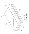
- an adjustable pillow device according to the present invention is shown to include abase 3, a pillow unit 4 , an adjustable supporting unit 5, and a cushioning cover 6.
- the base 3 is rectangular, and is adapted to be disposed on a supporting surface 100 (see Figure 5 ).
- the base 3 is formed with two first openings 31 aligned with each other in a first direction (X), and two second openings 31' (only one is shown) opposite to each other in a second direction (Y) perpendicular to the first direction (X) such that the first openings 31 are disposed between the second openings 31'.
- the base 3 is further formed with two first guiding units each having a plurality of extending vertically guiding rods 32 that are disposed around a corresponding one of the first openings 31, and two second guiding units each having a plurality of extending vertically guiding rods 32' that are disposed around a corresponding one of the second openings 31'. That is, the guiding rods 32, 32' extend in a vertical direction (Z) perpendicular to the first and second directions (X, Y).
- the pillow unit 4 is disposed above the base 3 and is movable vertically relative to the base 3.
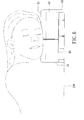
- the pillow unit 4 includes rigid first and second pillow bodies 41, 42 aligned with each other in the first direction (X) and adapted for supporting respectively the head and neck of a human body thereon when the human body lies flat on the supporting surface 100, as shown in Figure 5 , and a pair of rigid third pillow bodies 43 opposite to each other in the second direction (Y) such that the first and second pillow bodies 41, 42 are disposed between the third pillow bodies 43.
- Each third pillow body 43 is adapted for supporting the head of the human body thereon when the human body lies on its side on the supporting surface 100, as shown in Figure 6 , and has a top surface higher than those of the first and second pillow bodies 41, 42, as shown in Figure 3 . It is noted that, in this embodiment, the third pillow bodies 43 are spaced apart from the second pillow body 42.
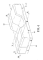
- the pillow unit 4 further includes a pair of resilient connecting members 44.
- Each connecting member 44 consists of a plurality of resilient ribs, has a connecting end 441 connected to a corresponding one of opposite sides of the second pillow body 42 in the second direction (Y), a free end 442 opposite to the connecting end 441 in the second direction (Y) and extending into a corresponding one of the third pillow bodies 43 through a plurality of through holes 431 therein, and a guiding portion 443 connected to the connecting end 441 and disposed between the second pillow body 42 and the corresponding one of the third pillow bodies 43 such that the second pillow body 42 cooperates with the guiding portions 443 of the connecting members 44 to constitute a concave structure interconnecting the third pillow bodies 43, as shown in Figures 3 and 7 .
- the supporting unit 5 is mounted on the base 3, is disposed between the base 3 and the pillow unit 4, and is operable so as to support the pillow unit 4 in a desired state.
- the supporting unit 5 is operable to adjust each of the first, second and third pillow bodies 41, 42, 43 in the vertical direction (Z) so that each of the first, second and third pillow bodies 41, 42, 43 is supported by the supporting unit 5 at a desired height relative to the supporting surface 100 when the pillow unit 4 is in the desired state.
- a desired height difference is formed between the first and second pillow bodies 41, 42.
- the supporting unit 5 includes a pair of first supporting members 50 corresponding respectively to the first and second pillow bodies 41, 42, and a pair of second supporting members 50' corresponding respectively to the third pillow bodies 43.
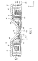
- Each first supporting member 50 is operable so as to support a corresponding one of the first and second pillow bodies 41, 42 at the desired height relative to the supporting surface 100, and includes a mounting plate 51, a pair of supporting seats 52 and a spring-loaded engaging unit 53.
- the mounting plate 51 is mounted on a bottom side of the corresponding one of the first and second pillow bodies 41, 42, and is formed with a plurality of through holes 511 permitting extension of the guiding rods 32 of a corresponding first guiding unit therethrough such that the mounting plate 51 is guided by the guiding rods 32 of the corresponding first guiding unit to move relative to the base 3 in the vertical direction (Z).
- the supporting seats 52 are opposite to each other in the second direction (Y), are mounted on the base 3, and flank the mounting plate 51.
- Each of the supporting seats 52 has a side surface facing the other one of the supporting seats 52 and formed with a plurality of engaging grooves 521.
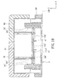
- the spring-loaded engaging unit 53 is disposed under the mounting plate 51 and above a corresponding one of the first openings 31 in the base 3, and is operable to engage releasably the supporting seats 52 for supporting an assembly of the mounting plate 51 and the corresponding one of the first and second pillow bodies 41, 42 thereon such that the corresponding one of the first and second pillow bodies 41, 42 is positioned at the desired height relative to the supporting surface 100.
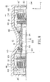
- the spring-loaded engaging unit 53 is received in a receiving groove 512 in a bottom side of the mounting plate 51 (see Figure 5 ), and includes two engaging pieces 531, and a spring piece 532 disposed between and abutting respectively against the engaging pieces 531 for biasing each of the engaging pieces 531 to engage a selected one of the engaging grooves 521 in a corresponding one of the supporting seats 52, as shown in Figure 7 .
- each second supporting member 50' is operable so as to support a corresponding one of the third pillow bodies 43 at the desired height relative to the supporting surface 100, and includes a mounting plate 51', a pair of supporting seats 52' and a spring-loaded engaging unit 53'.
- the mounting plate 51' is mounted on a bottom side of the corresponding one of the third pillow bodies 43, and is formed with a plurality of through holes 511' permitting extension of the guiding rods 32' of a corresponding second guiding unit therethrough such that the mounting plate 51' is guided by the guiding rods 32' of the corresponding second guiding unit to move relative to the base 3 in the vertical direction (Z).
- the supporting seats 52' are opposite to each other in the first direction (X), are mounted on the base 3, and flank the mounting plate 51'.
- Each of the supporting seats 52' has a side surface facing the other one of the supporting seats 52' and formed with a plurality of engaging grooves 521'.
- the spring-loaded engaging unit 53' is disposed under the mounting plate 51' and above a corresponding one of the second openings 31' in the base 3, and is operable to engage releasably the supporting seats 52' for supporting an assembly of the mounting plate 51' and the corresponding one of the third pillow bodies 43 thereon such that the corresponding one of the third pillow bodies 43 is positioned at the desired height relative to the supporting surface 100.
- the spring-loaded engaging unit 53' is received in a receiving groove 512' in a bottom side of the mounting plate 51' (see Figure 9 ), and includes two engaging pieces 531', and a spring piece 532' disposed between and abutting respectively against the engaging pieces 531' for biasing each of the engaging pieces 531' to engage a selected one of the engaging grooves 521' in a corresponding one of the supporting seats 52', as shown in Figure 9 .
- the cushioning cover 6 covers the pillow unit 4 and the base 3.
- the cushioning cover 6 includes complementary first, second and third cover bodies 61, 62, 63, wherein the first and second cover bodies 61, 62 cover the pillow unit 4, and the third cover body 63 surrounds the base 3.
- the mounting plate 51, 51' of the corresponding one of the supporting members 50, 50' is moved in the vertical direction (Z) until a corresponding one of the first, second and third pillow bodies 41, 42, 43 reaches the desired position. Then, the spring piece 532, 532' of the spring-loaded engaging unit 53, 53' of the corresponding one of the supporting members 50, 50' is released such that the engaging pieces 531, 531' of the spring-loaded engaging unit 53, 53' of the corresponding one of the supporting members 50, 50' engage respectively the corresponding engaging grooves 521, 521' in the supporting seats 52, 52' of the corresponding one of the supporting members 50, 50'.
- Figure 8 illustrates that the second pillow body 42 is adjusted to a higher position as compared to that in Figure 7
- Figure 10 illustrates that the third pillow body 43 is adjusted to a higher position as compared to that in Figure 9 .
Landscapes
- Health & Medical Sciences (AREA)
- General Health & Medical Sciences (AREA)
- Otolaryngology (AREA)
- Pulmonology (AREA)
- Bedding Items (AREA)
Claims (10)
- AnpassbareKissenvorrichtung, die folgendes umfasst:eine Basis (3), die auf einer stützenden Oberfläche (100) angeordnet ist,eine Kisseneinheit (4), die oberhalb der genannten Basis (3) angeordnet und im Verhältnis zu der genannten Basis (3) beweglich ist; undeine anpassbare stützende Einheit (5), die auf der genannten Basis (3) angebracht ist, angeordnet zwischender genannten Basis (3) und der genannten Kisseneinheit (4), und wobei sie so funktionsfähig ist, dass sie die genannte Kisseneinheit (4) in einem gewünschten Zustand stützt;wobei die genannte Kisseneinheit (4) steife erste und zweite Kissenkörper (41, 42) aufweist, die zueinander in einer ersten Richtung (X) ausgerichtet sind und entsprechend den Kopf und Nacken eines menschlichen Körpers daraufstützen können, wenn der menschliche Körper flach auf der stützenden Oberfläche (100) liegt;wobei die genannte stützende Einheit (5) so funktionsfähig ist, dass sie zumindest einen der genannten ersten und zweiten Kissenkörper (41, 42) vertikal anpassen kann, so dass ein gewünschter Höhenunterschied zwischenden genannten ersten und zweiten Kissenkörpern (41, 42) gebildet wird, wenn sich die genannte Kisseneinheit in dem gewünschten Zustand befindet, wobei die genannte stützende Einheit (5) ein Paar erster stützender Elemente (50) aufweist, die entsprechend den genannten ersten und zweiten Kissenkörpern (41, 42) entsprechen, wobei jedes der genannten ersten stützenden Elemente (50) so funktionsfähig ist, dass es einen entsprechenden der genannten ersten und zweiten Kissenkörper (41, 42) auf einer gewünschten Höhe im Verhältnis zu der stützenden Oberfläche (100) stützt, wenn sich die genannte Kisseneinheit (4) in dem gewünschten Zustand befindet;dadurch gekennzeichnet, dass die genannte Basis (3) mit zwei ersten Öffnungen (31) ausgebildet ist, die entsprechend den genannten ersten stützenden Elementen (50) entsprechen; undwobei jedes der genannten ersten stützenden Elemente (50) folgendes aufweist:eine Befestigungsplatte (51), die an einer Unterseite des entsprechenden der genannten ersten und zweiten Kissenkörper (41, 42) angebracht und im Verhältnis zu der genannten Basis (3) vertikal beweglich ist;ein Paar stützender Sitze (52), die in einer zweiten Richtung (Y), die senkrecht zu der ersten Richtung (X) verläuft, entgegengesetzt zueinander an der genannten Basis (3) angebracht sind und die genannte Befestigungsplatte (51) flankieren; undeine federbelastete Eingriffseinheit (53), die unter der genannten Befestigungsplatte (51) und über einer entsprechenden der genannten ersten Öffnungen (31) in der genannten Basis (3) angeordnet und so funktionsfähig ist, dass sie trennbar mit den genannten stützenden Sitzen (52) eingreift, um einen Zusammenbau der genannten Befestigungsplatte (51) und des entsprechenden einen der genannten ersten und zweiten Kissenkörper (41, 42) daraufzu tragen, so dass der entsprechende eine der genannten ersten und zweiten Kissenkörper (41, 42) auf einer gewünschten Höhe im Verhältnis zu der stützenden Oberfläche (100) positioniert ist.
- AnpassbareKissenvorrichtung nach Anspruch 1, wobei diese ferner dadurch gekennzeichnet ist, dass:jeder der genannten stützenden Sitze (52) jedes der genannten ersten stützenden Elemente (50) eine Seitenoberfläche aufweist, die zu dem anderen der genannten stützenden Sitze (52) eines entsprechenden der genannten ersten stützenden Elemente (50) ausgerichtet und mit eine Mehrzahl von eingreifenden Rillen (521) ausgebildet ist; unddie genannte federbelastete Eingriffseinheit (53) jedes der genannten ersten stützenden Elemente (50) zwei eingreifende Stücke (531) und ein Federstück (532) aufweist, das zwischenden genannten eingreifenden Stücken (531) angeordnet ist und an diese anstößt, um jedes der genannten eingreifenden Stücke (531) so vorzubelasten, dass es mit einer ausgesuchten der genannten eingreifenden Rillen (521) in einem entsprechenden der genannten Sitze (52) des entsprechenden einen der genannten ersten stützenden Elemente (50) eingreift.
- AnpassbareKissenvorrichtung nach Anspruch 1, wobei diese ferner dadurch gekennzeichnet ist, dass die genannte Basis (3) ferner mit zwei ersten Führungseinheiten ausgebildet ist, wobei jede der genannten ersten Führungseinheiten eine Mehrzahl von Führungsstäben (32) aufweist, die sich vertikal durch die genannte Befestigungsplatte (51) eines entsprechenden der genannten ersten stützenden Elemente (50) erstrecken, für eine vertikale Bewegung der genannten Befestigungsplatte (51) des entsprechenden einen der genannten ersten stützenden Elemente (50) im Verhältnis zu der genannten Basis (3).
- AnpassbareKissenvorrichtung nach Anspruch 1, wobei diese ferner dadurch gekennzeichnet ist, dass die genannte Kisseneinheit (4) ferner ein Paar steifer dritter Kissenkörper (43) entgegengesetzt zueinander in der zweiten Richtung (Y) aufweist, so dass die genannten ersten und zweiten Kissenkörper (41, 42) zwischenden genannten dritten Kissenkörpern (43) angeordnet sind, wobei jeder der genannten dritten Kissenkörper (43) in der Lage ist, darauf den Kopf des menschlichen Körpers zu stützen, wenn der menschliche Körper auf dessen Seite auf der stützenden Oberfläche (100) liegt, und mit einer oberen Oberfläche,die höher ist als die Oberflächen der genannten ersten und zweiten Kissenkörper (41,42).
- AnpassbareKissenvorrichtung nach Anspruch 4, wobei diese ferner dadurch gekennzeichnet ist, dass:die genannten dritten Kissenkörper (43) mit Zwischenabständen zu dem genannten zweiten Kissenkörper (41, 42) angeordnet sind; undwobei die genannte Kisseneinheit (4) ferner ein Paar elastischer Verbindungselemente (44) aufweist, die jeweils ein Verbindungsende (441) aufweisen, das mit einer entsprechenden der gegenüberliegenden Seiten des genannten zweiten Kissenkörpers (42) in der zweiten Richtung (Y) verbundensind, mit einem freien Ende (442) entgegengesetzt zu dem genannten Verbindungsende (441) in der zweiten Richtung (Y), und wobei sich das Ende in einen entsprechenden der genannten dritten Kissenkörper (43) erstreckt, und mit einem Führungsteilstück (443), das mit dem genannten Verbindungsende verbundenist und sich zwischendem genannten zweiten Kissenkörper (42) und dem entsprechenden einen der genannten dritten Kissenkörper (43) befindet, so dass der genannte zweite Kissenkörper (42) mit den genannten Führungsteilstücken (443) der genannten Verbindungselemente (44) zusammenarbeitet, so dass eine konkave Struktur gebildet wird, welche die genannten dritten Kissenkörper (43) miteinander verbindet.
- AnpassbareKissenvorrichtung nach Anspruch 4, wobei diese ferner dadurch gekennzeichnet ist, dass die genannte stützende Einheit (5) ferner ein Paar zweiter stützender Elemente (50') aufweist, die entsprechend den genannten dritten Kissenkörpern (43) entsprechen, wobei jedes der genannten zweiten stützenden Elemente (50') so funktionsfähig ist, dass es einen entsprechenden einen der genannten dritten Kissenkörper (43) auf einer gewünschten Höhe stützt, wenn sich die genannte Kisseneinheit (4) in dem gewünschten Zustand befindet.
- AnpassbareKissenvorrichtung nach Anspruch 6, wobei diese ferner dadurch gekennzeichnet ist, dass:die genannte Basis (3) ferner mit zwei Öffnungen (31') ausgebildet ist, welche entsprechend den genannten zweiten stützenden Elementen (50') entsprechen; undwobei jedes der genannten zweiten stützenden Elemente (50') folgendes aufweist:eine Befestigungsplatte (51'), die an einer Unterseite des entsprechenden einen der genannten dritten Kissenkörper (43) angebracht und vertikal im Verhältnis zu der genannten Basis (3) beweglich ist;ein paar stützender Sitze (52'), die in die erste Richtung (X) entgegengesetzt zueinander sind, wobei sie an der genannten Basis (3) angebracht sind und die genannte Befestigungsplatte (51') flankieren; undeine federbelastete Eingriffseinheit (53'), die unter der genannten Befestigungsplatte (51') und über einer entsprechenden einen der genannten zweiten Öffnungen (31') in der genannten Basis (3) angeordnet ist, und wobei sie so funktionsfähig ist, dass sie trennbar mit den genannten stützenden Sitzen (52') eingreift, um einen Zusammenbau der genannten Befestigungsplatte (51') und des entsprechenden einen der genannten dritten Kissenkörper (43) daraufzu stützen, so dass der entsprechende eine der genannten dritten Kissenkörper (43) auf der gewünschten Höhe im Verhältnis zu der stützenden Oberfläche (100) positioniert ist.
- AnpassbareKissenvorrichtung nach Anspruch 7, wobei diese ferner dadurch gekennzeichnet ist, dass:jeder der genannten stützenden Sitze (52') jedes der genannten zweiten stützenden Elemente (50') eine seitliche Oberfläche aufweist, die zu dem anderen einen der genannten stützenden Sitze (52') eines entsprechenden einen der genannten zweiten stützenden Elemente (50') ausgerichtet ist und mit einer Mehrzahl von eingreifenden Rillen (521') ausgebildet ist; undwobei die genannte federbelastete Eingriffseinheit (53') jedes der genannten zweiten stützenden Elemente (50') zwei eingreifende Stücke (531') und ein Federstück (532') aufweist, das zwischenden genannten eingreifenden Stücken (531') angeordnet ist und an diese anstößt, um jedes der genannten eingreifenden Stücke (531') so vorzubelasten, dass es mit einer ausgesuchten einen der genannten eingreifenden Rillen (521') in einem entsprechenden einen der genannten stützenden Elemente (52') des entsprechenden einen der genannten zweiten stützenden Elemente (50') eingreift.
- AnpassbareKissenvorrichtung nach Anspruch 7, wobei diese ferner dadurch gekennzeichnet ist, dass die genannte Basis (3) ferner mit zwei zweiten Führungseinheiten ausgebildet ist, wobei jede der genannten zweiten Führungseinheiten eine Mehrzahl von Führungsstäben (32') aufweist, die sich vertikal durch die genannte Befestigungsplatte (51') eines entsprechenden einen der genannten zweiten stützenden Elemente (50') erstrecken, um die vertikale Bewegung der genannten Befestigungsplatte (51') des entsprechenden einen der genannten zweiten stützenden Elemente (50') im Verhältnis zu der genannten Basis (3) zu führen.
- AnpassbareKissenvorrichtung nach Anspruch 1, wobei diese ferner gekennzeichnet ist durch einen polsternden Bezug (6) zum Abdecken der genannten Kisseneinheit (4) und der genannten Basis (3).
Applications Claiming Priority (1)
| Application Number | Priority Date | Filing Date | Title |
|---|---|---|---|
| TW097116787A TW200946061A (en) | 2008-05-07 | 2008-05-07 | Pillow able to adjust the height |
Publications (2)
| Publication Number | Publication Date |
|---|---|
| EP2116156A1 EP2116156A1 (de) | 2009-11-11 |
| EP2116156B1 true EP2116156B1 (de) | 2012-02-08 |
Family
ID=40872437
Family Applications (1)
| Application Number | Title | Priority Date | Filing Date |
|---|---|---|---|
| EP09159083A Ceased EP2116156B1 (de) | 2008-05-07 | 2009-04-29 | Verstellbare Kissenvorrichtung |
Country Status (11)
| Country | Link |
|---|---|
| US (1) | US7856687B2 (de) |
| EP (1) | EP2116156B1 (de) |
| JP (1) | JP5005729B2 (de) |
| KR (1) | KR101139889B1 (de) |
| AT (1) | ATE544377T1 (de) |
| AU (1) | AU2009201784A1 (de) |
| BR (1) | BRPI0901460A2 (de) |
| CA (1) | CA2665264C (de) |
| MY (1) | MY148793A (de) |
| NZ (1) | NZ576565A (de) |
| TW (1) | TW200946061A (de) |
Families Citing this family (27)
| Publication number | Priority date | Publication date | Assignee | Title |
|---|---|---|---|---|
| US20110094033A1 (en) * | 2009-10-28 | 2011-04-28 | Zinus Inc. | Anti-snore neck-support contour pillow |
| KR100987961B1 (ko) * | 2007-11-08 | 2010-10-18 | 남해현 | 머리받침구가 구비된 의자 |
| TW200946061A (en) * | 2008-05-07 | 2009-11-16 | hong-jian Zhou | Pillow able to adjust the height |
| TW201201748A (en) * | 2010-07-02 | 2012-01-16 | Zhou Zhe Yang | Ergonomics pillow |
| US20120073057A1 (en) * | 2010-09-29 | 2012-03-29 | Sramek Roger A | Pillow having structurally varying core and cover |
| WO2012054963A1 (en) * | 2010-10-25 | 2012-05-03 | Tri-Cycle Pty Ltd | Head and/or neck support device and method |
| US9420905B2 (en) * | 2011-09-02 | 2016-08-23 | Backjoy Orthotics, Llc | Cushion device |
| US9635962B2 (en) * | 2012-04-12 | 2017-05-02 | Cabeau, Inc. | Travel pillow with lateral and rear support bar and a flat and thin back |
| US8893334B1 (en) * | 2013-01-18 | 2014-11-25 | Danny C. Wong | Orthopedic pillows |
| US9138087B2 (en) * | 2014-02-07 | 2015-09-22 | Latitude Innovations | Universal prone/supine pillow |
| JP6253799B2 (ja) * | 2014-03-03 | 2017-12-27 | モテックス プロダクツ カンパニー リミテッド | 高低調節枕 |
| US10321765B2 (en) | 2014-03-11 | 2019-06-18 | Cabeau, Inc. | Travel pillow |
| US9968197B2 (en) | 2014-03-11 | 2018-05-15 | Cabeau, Inc. | Travel pillow |
| USD762400S1 (en) | 2014-10-20 | 2016-08-02 | Cabeau, Inc. | Travel pillow |
| USD790880S1 (en) | 2015-09-29 | 2017-07-04 | Cabeau, Inc. | Neck pillow |
| WO2017058914A1 (en) | 2015-09-29 | 2017-04-06 | Cabeau, Inc. | Neck pillow with chin supports, multiple anchor points, and magnetic clip |
| CN105105585B (zh) * | 2015-09-29 | 2017-08-25 | 黄子凡 | 枕头 |
| KR200484694Y1 (ko) * | 2015-12-14 | 2017-10-18 | 김정국 | 기능성 경추 및 날개 베개 |
| JP2018027303A (ja) * | 2016-08-15 | 2018-02-22 | ▲黄▼賢達Huang, Hsien−Ta | 昇降式枕 |
| US10722058B1 (en) | 2017-03-29 | 2020-07-28 | Zelzeos LLC | Therapeutic pillow |
| KR101854387B1 (ko) * | 2017-05-10 | 2018-05-08 | 주식회사 모텍스 | 저부 장착형 핸들을 가진 높낮이 조절 베개 |
| CN107080411A (zh) * | 2017-06-14 | 2017-08-22 | 山东师范大学 | 一种防静电的可调角度高度的睡眠枕及方法 |
| US10321776B2 (en) | 2017-09-28 | 2019-06-18 | Mohammad Hadi Hafeznezami | Adjustable pillow and methods of making and using same |
| TWI830992B (zh) * | 2021-03-18 | 2024-02-01 | 洪順天 | 受力分析系統 |
| CN115105326A (zh) * | 2021-04-29 | 2022-09-27 | 河南省人民医院 | 缓解胃食道反流垫 |
| CN115887136B (zh) * | 2022-12-30 | 2024-06-18 | 贵州锐诚翔科技发展有限公司 | 一种康复枕 |
| TWI866854B (zh) * | 2024-05-09 | 2024-12-11 | 王明正 | 斜面充氣枕 |
Family Cites Families (18)
| Publication number | Priority date | Publication date | Assignee | Title |
|---|---|---|---|---|
| US120498A (en) * | 1871-10-31 | Improvement in adjustable bolsters | ||
| JPH0371127U (de) * | 1989-11-14 | 1991-07-18 | ||
| US5353457A (en) * | 1993-10-06 | 1994-10-11 | Chu Hsu M | Pillow with a height adjustment device |
| JP3039327U (ja) * | 1996-12-19 | 1997-07-15 | 盛俊 伊芸 | 枕 |
| JPH11253287A (ja) | 1998-03-09 | 1999-09-21 | Koji Oguri | 整体矯正枕 |
| JP2000005011A (ja) * | 1998-06-18 | 2000-01-11 | Setsuo Tanaka | 枕 |
| JP3071127U (ja) * | 2000-02-18 | 2000-08-29 | 豊商鋼材株式会社 | 形状・高さ調整式安眠枕およびその調整装置 |
| US6349438B1 (en) * | 2000-04-24 | 2002-02-26 | Gerald Coleman | Hydraulically actuated variable height leg pillow support apparatus |
| JP2001327382A (ja) * | 2000-05-22 | 2001-11-27 | Takao Kenkogu:Kk | 枕充填体ユニット、及びこれを備えている枕 |
| JP2002102039A (ja) * | 2000-10-03 | 2002-04-09 | Kazuo Okuno | 高さ調整枕 |
| CN2482912Y (zh) * | 2001-04-25 | 2002-03-27 | 刘宇峰 | 一种可升降的睡枕 |
| JP2004147889A (ja) * | 2002-10-31 | 2004-05-27 | Shingiken:Kk | 枕 |
| JP4632343B2 (ja) * | 2003-01-29 | 2011-02-16 | 和夫 小柴 | 枕 |
| JP4352750B2 (ja) * | 2003-04-25 | 2009-10-28 | パナソニック株式会社 | 枕 |
| CN1937942A (zh) * | 2004-08-04 | 2007-03-28 | 株式会社医研工业 | 枕头 |
| KR100628005B1 (ko) * | 2005-03-16 | 2006-09-26 | 김치왕 | 높이가변식 베게 |
| JP2007000397A (ja) * | 2005-06-24 | 2007-01-11 | Seketsu Ho | 枕 |
| TW200946061A (en) * | 2008-05-07 | 2009-11-16 | hong-jian Zhou | Pillow able to adjust the height |
-
2008
- 2008-05-07 TW TW097116787A patent/TW200946061A/zh not_active IP Right Cessation
-
2009
- 2009-04-28 NZ NZ576565A patent/NZ576565A/en not_active IP Right Cessation
- 2009-04-29 EP EP09159083A patent/EP2116156B1/de not_active Ceased
- 2009-04-29 AT AT09159083T patent/ATE544377T1/de active
- 2009-04-30 KR KR1020090038223A patent/KR101139889B1/ko not_active Expired - Fee Related
- 2009-04-30 US US12/433,444 patent/US7856687B2/en not_active Expired - Fee Related
- 2009-05-01 JP JP2009111905A patent/JP5005729B2/ja not_active Expired - Fee Related
- 2009-05-04 MY MYPI20091800A patent/MY148793A/en unknown
- 2009-05-05 CA CA2665264A patent/CA2665264C/en not_active Expired - Fee Related
- 2009-05-05 AU AU2009201784A patent/AU2009201784A1/en not_active Abandoned
- 2009-05-06 BR BRPI0901460-8A patent/BRPI0901460A2/pt not_active IP Right Cessation
Also Published As
| Publication number | Publication date |
|---|---|
| CA2665264A1 (en) | 2009-11-07 |
| TW200946061A (en) | 2009-11-16 |
| US20090276960A1 (en) | 2009-11-12 |
| TWI351938B (de) | 2011-11-11 |
| KR101139889B1 (ko) | 2012-05-02 |
| MY148793A (en) | 2013-05-31 |
| EP2116156A1 (de) | 2009-11-11 |
| NZ576565A (en) | 2010-10-29 |
| US7856687B2 (en) | 2010-12-28 |
| KR20090116634A (ko) | 2009-11-11 |
| JP5005729B2 (ja) | 2012-08-22 |
| JP2009268907A (ja) | 2009-11-19 |
| BRPI0901460A2 (pt) | 2010-01-26 |
| CA2665264C (en) | 2012-06-26 |
| ATE544377T1 (de) | 2012-02-15 |
| AU2009201784A1 (en) | 2009-11-26 |
Similar Documents
| Publication | Publication Date | Title |
|---|---|---|
| EP2116156B1 (de) | Verstellbare Kissenvorrichtung | |
| AU688594B2 (en) | Wrist rest assembly | |
| US5342005A (en) | Arm support apparatus for keyboard and other apparatus requiring repetitive hand operation | |
| KR101059097B1 (ko) | 의자의 허리받침용 시트 | |
| US20120172775A1 (en) | Wrist protector | |
| KR20140004925A (ko) | 가변형 등받이를 구비한 의자 | |
| KR102041978B1 (ko) | 의자의 팔걸이 조절장치 | |
| MX2009004876A (es) | Dispositivo de almohada ajustable. | |
| KR101069769B1 (ko) | 의자 | |
| CN211156790U (zh) | 一种轮椅头靠的定位机构 | |
| KR101068588B1 (ko) | 높이 조정이 가능한 베개 | |
| KR100539367B1 (ko) | 의자 팔걸이의 높이조절장치 | |
| JP4036919B2 (ja) | 椅子における可動肘当 | |
| JP3102677U (ja) | 運動用バランス器具 | |
| JP3116444U (ja) | 指圧器 | |
| JP4563111B2 (ja) | 椅子用バックレスト | |
| KR20120007229U (ko) | 의자를 구비한 책상 | |
| CN222946594U (zh) | 一种具有自撑型结构的汽车座椅 | |
| JP5238204B2 (ja) | 携帯式正座用補助椅子 | |
| JP3171110U (ja) | ソファーベッド | |
| JP3223359U (ja) | 枕保持器具 | |
| KR20230164402A (ko) | 허벅지 받침장치 | |
| CN210748339U (zh) | 一种用于儿童椅子的矫姿双靠背机构 | |
| KR200270286Y1 (ko) | 키보드 및 마우스 거치대 | |
| JP3116034U (ja) | ショッピングカート用腕載せ台 |
Legal Events
| Date | Code | Title | Description |
|---|---|---|---|
| PUAI | Public reference made under article 153(3) epc to a published international application that has entered the european phase |
Free format text: ORIGINAL CODE: 0009012 |
|
| AK | Designated contracting states |
Kind code of ref document: A1 Designated state(s): AT BE BG CH CY CZ DE DK EE ES FI FR GB GR HR HU IE IS IT LI LT LU LV MC MK MT NL NO PL PT RO SE SI SK TR |
|
| 17P | Request for examination filed |
Effective date: 20100422 |
|
| 17Q | First examination report despatched |
Effective date: 20100602 |
|
| GRAP | Despatch of communication of intention to grant a patent |
Free format text: ORIGINAL CODE: EPIDOSNIGR1 |
|
| GRAS | Grant fee paid |
Free format text: ORIGINAL CODE: EPIDOSNIGR3 |
|
| GRAA | (expected) grant |
Free format text: ORIGINAL CODE: 0009210 |
|
| AK | Designated contracting states |
Kind code of ref document: B1 Designated state(s): AT BE BG CH CY CZ DE DK EE ES FI FR GB GR HR HU IE IS IT LI LT LU LV MC MK MT NL NO PL PT RO SE SI SK TR |
|
| REG | Reference to a national code |
Ref country code: GB Ref legal event code: FG4D |
|
| REG | Reference to a national code |
Ref country code: AT Ref legal event code: REF Ref document number: 544377 Country of ref document: AT Kind code of ref document: T Effective date: 20120215 Ref country code: CH Ref legal event code: EP |
|
| REG | Reference to a national code |
Ref country code: DE Ref legal event code: R096 Ref document number: 602009005149 Country of ref document: DE Effective date: 20120405 |
|
| REG | Reference to a national code |
Ref country code: NL Ref legal event code: VDEP Effective date: 20120208 |
|
| LTIE | Lt: invalidation of european patent or patent extension |
Effective date: 20120208 |
|
| PG25 | Lapsed in a contracting state [announced via postgrant information from national office to epo] |
Ref country code: NL Free format text: LAPSE BECAUSE OF FAILURE TO SUBMIT A TRANSLATION OF THE DESCRIPTION OR TO PAY THE FEE WITHIN THE PRESCRIBED TIME-LIMIT Effective date: 20120208 Ref country code: LT Free format text: LAPSE BECAUSE OF FAILURE TO SUBMIT A TRANSLATION OF THE DESCRIPTION OR TO PAY THE FEE WITHIN THE PRESCRIBED TIME-LIMIT Effective date: 20120208 Ref country code: IS Free format text: LAPSE BECAUSE OF FAILURE TO SUBMIT A TRANSLATION OF THE DESCRIPTION OR TO PAY THE FEE WITHIN THE PRESCRIBED TIME-LIMIT Effective date: 20120608 Ref country code: HR Free format text: LAPSE BECAUSE OF FAILURE TO SUBMIT A TRANSLATION OF THE DESCRIPTION OR TO PAY THE FEE WITHIN THE PRESCRIBED TIME-LIMIT Effective date: 20120208 Ref country code: NO Free format text: LAPSE BECAUSE OF FAILURE TO SUBMIT A TRANSLATION OF THE DESCRIPTION OR TO PAY THE FEE WITHIN THE PRESCRIBED TIME-LIMIT Effective date: 20120508 |
|
| PG25 | Lapsed in a contracting state [announced via postgrant information from national office to epo] |
Ref country code: GR Free format text: LAPSE BECAUSE OF FAILURE TO SUBMIT A TRANSLATION OF THE DESCRIPTION OR TO PAY THE FEE WITHIN THE PRESCRIBED TIME-LIMIT Effective date: 20120509 Ref country code: PL Free format text: LAPSE BECAUSE OF FAILURE TO SUBMIT A TRANSLATION OF THE DESCRIPTION OR TO PAY THE FEE WITHIN THE PRESCRIBED TIME-LIMIT Effective date: 20120208 Ref country code: FI Free format text: LAPSE BECAUSE OF FAILURE TO SUBMIT A TRANSLATION OF THE DESCRIPTION OR TO PAY THE FEE WITHIN THE PRESCRIBED TIME-LIMIT Effective date: 20120208 Ref country code: PT Free format text: LAPSE BECAUSE OF FAILURE TO SUBMIT A TRANSLATION OF THE DESCRIPTION OR TO PAY THE FEE WITHIN THE PRESCRIBED TIME-LIMIT Effective date: 20120608 Ref country code: BE Free format text: LAPSE BECAUSE OF FAILURE TO SUBMIT A TRANSLATION OF THE DESCRIPTION OR TO PAY THE FEE WITHIN THE PRESCRIBED TIME-LIMIT Effective date: 20120208 Ref country code: LV Free format text: LAPSE BECAUSE OF FAILURE TO SUBMIT A TRANSLATION OF THE DESCRIPTION OR TO PAY THE FEE WITHIN THE PRESCRIBED TIME-LIMIT Effective date: 20120208 |
|
| REG | Reference to a national code |
Ref country code: AT Ref legal event code: MK05 Ref document number: 544377 Country of ref document: AT Kind code of ref document: T Effective date: 20120208 |
|
| PG25 | Lapsed in a contracting state [announced via postgrant information from national office to epo] |
Ref country code: CY Free format text: LAPSE BECAUSE OF FAILURE TO SUBMIT A TRANSLATION OF THE DESCRIPTION OR TO PAY THE FEE WITHIN THE PRESCRIBED TIME-LIMIT Effective date: 20120208 |
|
| PG25 | Lapsed in a contracting state [announced via postgrant information from national office to epo] |
Ref country code: SI Free format text: LAPSE BECAUSE OF FAILURE TO SUBMIT A TRANSLATION OF THE DESCRIPTION OR TO PAY THE FEE WITHIN THE PRESCRIBED TIME-LIMIT Effective date: 20120208 Ref country code: EE Free format text: LAPSE BECAUSE OF FAILURE TO SUBMIT A TRANSLATION OF THE DESCRIPTION OR TO PAY THE FEE WITHIN THE PRESCRIBED TIME-LIMIT Effective date: 20120208 Ref country code: RO Free format text: LAPSE BECAUSE OF FAILURE TO SUBMIT A TRANSLATION OF THE DESCRIPTION OR TO PAY THE FEE WITHIN THE PRESCRIBED TIME-LIMIT Effective date: 20120208 Ref country code: SE Free format text: LAPSE BECAUSE OF FAILURE TO SUBMIT A TRANSLATION OF THE DESCRIPTION OR TO PAY THE FEE WITHIN THE PRESCRIBED TIME-LIMIT Effective date: 20120208 Ref country code: DK Free format text: LAPSE BECAUSE OF FAILURE TO SUBMIT A TRANSLATION OF THE DESCRIPTION OR TO PAY THE FEE WITHIN THE PRESCRIBED TIME-LIMIT Effective date: 20120208 Ref country code: CZ Free format text: LAPSE BECAUSE OF FAILURE TO SUBMIT A TRANSLATION OF THE DESCRIPTION OR TO PAY THE FEE WITHIN THE PRESCRIBED TIME-LIMIT Effective date: 20120208 |
|
| PG25 | Lapsed in a contracting state [announced via postgrant information from national office to epo] |
Ref country code: IT Free format text: LAPSE BECAUSE OF FAILURE TO SUBMIT A TRANSLATION OF THE DESCRIPTION OR TO PAY THE FEE WITHIN THE PRESCRIBED TIME-LIMIT Effective date: 20120208 Ref country code: MC Free format text: LAPSE BECAUSE OF NON-PAYMENT OF DUE FEES Effective date: 20120430 Ref country code: SK Free format text: LAPSE BECAUSE OF FAILURE TO SUBMIT A TRANSLATION OF THE DESCRIPTION OR TO PAY THE FEE WITHIN THE PRESCRIBED TIME-LIMIT Effective date: 20120208 |
|
| PLBE | No opposition filed within time limit |
Free format text: ORIGINAL CODE: 0009261 |
|
| STAA | Information on the status of an ep patent application or granted ep patent |
Free format text: STATUS: NO OPPOSITION FILED WITHIN TIME LIMIT |
|
| 26N | No opposition filed |
Effective date: 20121109 |
|
| PG25 | Lapsed in a contracting state [announced via postgrant information from national office to epo] |
Ref country code: AT Free format text: LAPSE BECAUSE OF FAILURE TO SUBMIT A TRANSLATION OF THE DESCRIPTION OR TO PAY THE FEE WITHIN THE PRESCRIBED TIME-LIMIT Effective date: 20120208 |
|
| PG25 | Lapsed in a contracting state [announced via postgrant information from national office to epo] |
Ref country code: MK Free format text: LAPSE BECAUSE OF FAILURE TO SUBMIT A TRANSLATION OF THE DESCRIPTION OR TO PAY THE FEE WITHIN THE PRESCRIBED TIME-LIMIT Effective date: 20120208 |
|
| REG | Reference to a national code |
Ref country code: DE Ref legal event code: R097 Ref document number: 602009005149 Country of ref document: DE Effective date: 20121109 |
|
| PG25 | Lapsed in a contracting state [announced via postgrant information from national office to epo] |
Ref country code: ES Free format text: LAPSE BECAUSE OF FAILURE TO SUBMIT A TRANSLATION OF THE DESCRIPTION OR TO PAY THE FEE WITHIN THE PRESCRIBED TIME-LIMIT Effective date: 20120519 Ref country code: IE Free format text: LAPSE BECAUSE OF NON-PAYMENT OF DUE FEES Effective date: 20120429 |
|
| PG25 | Lapsed in a contracting state [announced via postgrant information from national office to epo] |
Ref country code: BG Free format text: LAPSE BECAUSE OF FAILURE TO SUBMIT A TRANSLATION OF THE DESCRIPTION OR TO PAY THE FEE WITHIN THE PRESCRIBED TIME-LIMIT Effective date: 20120508 Ref country code: MT Free format text: LAPSE BECAUSE OF FAILURE TO SUBMIT A TRANSLATION OF THE DESCRIPTION OR TO PAY THE FEE WITHIN THE PRESCRIBED TIME-LIMIT Effective date: 20120208 |
|
| PG25 | Lapsed in a contracting state [announced via postgrant information from national office to epo] |
Ref country code: TR Free format text: LAPSE BECAUSE OF FAILURE TO SUBMIT A TRANSLATION OF THE DESCRIPTION OR TO PAY THE FEE WITHIN THE PRESCRIBED TIME-LIMIT Effective date: 20120208 |
|
| PG25 | Lapsed in a contracting state [announced via postgrant information from national office to epo] |
Ref country code: LU Free format text: LAPSE BECAUSE OF NON-PAYMENT OF DUE FEES Effective date: 20120429 |
|
| PG25 | Lapsed in a contracting state [announced via postgrant information from national office to epo] |
Ref country code: HU Free format text: LAPSE BECAUSE OF FAILURE TO SUBMIT A TRANSLATION OF THE DESCRIPTION OR TO PAY THE FEE WITHIN THE PRESCRIBED TIME-LIMIT Effective date: 20090429 |
|
| REG | Reference to a national code |
Ref country code: FR Ref legal event code: PLFP Year of fee payment: 8 |
|
| REG | Reference to a national code |
Ref country code: FR Ref legal event code: PLFP Year of fee payment: 9 |
|
| REG | Reference to a national code |
Ref country code: FR Ref legal event code: PLFP Year of fee payment: 10 |
|
| PGFP | Annual fee paid to national office [announced via postgrant information from national office to epo] |
Ref country code: DE Payment date: 20180426 Year of fee payment: 10 Ref country code: CH Payment date: 20180430 Year of fee payment: 10 |
|
| PGFP | Annual fee paid to national office [announced via postgrant information from national office to epo] |
Ref country code: FR Payment date: 20180425 Year of fee payment: 10 |
|
| PGFP | Annual fee paid to national office [announced via postgrant information from national office to epo] |
Ref country code: GB Payment date: 20180425 Year of fee payment: 10 |
|
| REG | Reference to a national code |
Ref country code: DE Ref legal event code: R119 Ref document number: 602009005149 Country of ref document: DE |
|
| REG | Reference to a national code |
Ref country code: CH Ref legal event code: PL |
|
| GBPC | Gb: european patent ceased through non-payment of renewal fee |
Effective date: 20190429 |
|
| PG25 | Lapsed in a contracting state [announced via postgrant information from national office to epo] |
Ref country code: LI Free format text: LAPSE BECAUSE OF NON-PAYMENT OF DUE FEES Effective date: 20190430 Ref country code: GB Free format text: LAPSE BECAUSE OF NON-PAYMENT OF DUE FEES Effective date: 20190429 Ref country code: CH Free format text: LAPSE BECAUSE OF NON-PAYMENT OF DUE FEES Effective date: 20190430 Ref country code: DE Free format text: LAPSE BECAUSE OF NON-PAYMENT OF DUE FEES Effective date: 20191101 |
|
| PG25 | Lapsed in a contracting state [announced via postgrant information from national office to epo] |
Ref country code: FR Free format text: LAPSE BECAUSE OF NON-PAYMENT OF DUE FEES Effective date: 20190430 |