EP2110933B1 - Motor, rotor structure and magnetic machine - Google Patents
Motor, rotor structure and magnetic machine Download PDFInfo
- Publication number
- EP2110933B1 EP2110933B1 EP08703706A EP08703706A EP2110933B1 EP 2110933 B1 EP2110933 B1 EP 2110933B1 EP 08703706 A EP08703706 A EP 08703706A EP 08703706 A EP08703706 A EP 08703706A EP 2110933 B1 EP2110933 B1 EP 2110933B1
- Authority
- EP
- European Patent Office
- Prior art keywords
- rotor
- magnetic
- magnetic poles
- induction magnetic
- induction
- Prior art date
- Legal status (The legal status is an assumption and is not a legal conclusion. Google has not performed a legal analysis and makes no representation as to the accuracy of the status listed.)
- Not-in-force
Links
Images


Classifications
-
- H—ELECTRICITY
- H02—GENERATION; CONVERSION OR DISTRIBUTION OF ELECTRIC POWER
- H02K—DYNAMO-ELECTRIC MACHINES
- H02K16/00—Machines with more than one rotor or stator
- H02K16/02—Machines with one stator and two or more rotors
-
- H—ELECTRICITY
- H02—GENERATION; CONVERSION OR DISTRIBUTION OF ELECTRIC POWER
- H02K—DYNAMO-ELECTRIC MACHINES
- H02K1/00—Details of the magnetic circuit
- H02K1/06—Details of the magnetic circuit characterised by the shape, form or construction
- H02K1/22—Rotating parts of the magnetic circuit
- H02K1/24—Rotor cores with salient poles ; Variable reluctance rotors
- H02K1/246—Variable reluctance rotors
-
- H—ELECTRICITY
- H02—GENERATION; CONVERSION OR DISTRIBUTION OF ELECTRIC POWER
- H02K—DYNAMO-ELECTRIC MACHINES
- H02K1/00—Details of the magnetic circuit
- H02K1/06—Details of the magnetic circuit characterised by the shape, form or construction
- H02K1/22—Rotating parts of the magnetic circuit
- H02K1/27—Rotor cores with permanent magnets
- H02K1/2706—Inner rotors
- H02K1/272—Inner rotors the magnetisation axis of the magnets being perpendicular to the rotor axis
- H02K1/274—Inner rotors the magnetisation axis of the magnets being perpendicular to the rotor axis the rotor consisting of two or more circumferentially positioned magnets
- H02K1/2753—Inner rotors the magnetisation axis of the magnets being perpendicular to the rotor axis the rotor consisting of two or more circumferentially positioned magnets the rotor consisting of magnets or groups of magnets arranged with alternating polarity
- H02K1/276—Magnets embedded in the magnetic core, e.g. interior permanent magnets [IPM]
-
- H—ELECTRICITY
- H02—GENERATION; CONVERSION OR DISTRIBUTION OF ELECTRIC POWER
- H02K—DYNAMO-ELECTRIC MACHINES
- H02K1/00—Details of the magnetic circuit
- H02K1/06—Details of the magnetic circuit characterised by the shape, form or construction
- H02K1/22—Rotating parts of the magnetic circuit
- H02K1/28—Means for mounting or fastening rotating magnetic parts on to, or to, the rotor structures
- H02K1/30—Means for mounting or fastening rotating magnetic parts on to, or to, the rotor structures using intermediate parts, e.g. spiders
-
- H—ELECTRICITY
- H02—GENERATION; CONVERSION OR DISTRIBUTION OF ELECTRIC POWER
- H02K—DYNAMO-ELECTRIC MACHINES
- H02K16/00—Machines with more than one rotor or stator
-
- H—ELECTRICITY
- H02—GENERATION; CONVERSION OR DISTRIBUTION OF ELECTRIC POWER
- H02K—DYNAMO-ELECTRIC MACHINES
- H02K19/00—Synchronous motors or generators
- H02K19/02—Synchronous motors
- H02K19/10—Synchronous motors for multi-phase current
- H02K19/103—Motors having windings on the stator and a variable reluctance soft-iron rotor without windings
-
- H—ELECTRICITY
- H02—GENERATION; CONVERSION OR DISTRIBUTION OF ELECTRIC POWER
- H02K—DYNAMO-ELECTRIC MACHINES
- H02K21/00—Synchronous motors having permanent magnets; Synchronous generators having permanent magnets
- H02K21/12—Synchronous motors having permanent magnets; Synchronous generators having permanent magnets with stationary armatures and rotating magnets
- H02K21/14—Synchronous motors having permanent magnets; Synchronous generators having permanent magnets with stationary armatures and rotating magnets with magnets rotating within the armatures
- H02K21/16—Synchronous motors having permanent magnets; Synchronous generators having permanent magnets with stationary armatures and rotating magnets with magnets rotating within the armatures having annular armature cores with salient poles
Definitions
- the present invention relates to a motor comprising: annular stators arranged so as to surround an axis; a first rotor rotatable around the axis; and a second rotor arranged between the stator and the first rotor, and rotatable around the axis.
- a conventional motor disclosed in the following Patent Publication 1, for example is known.
- This motor has an inner rotor, a stator, and an outer rotor.
- the inner rotor is in a columnar shape in which a plurality of permanent magnets slightly extending in the radial direction are arranged in the circumferential direction.
- the stator is in a cylindrical shape in which a plurality of armatures are arranged in the circumferential direction and fixed by a resin mold.
- the outer rotor is in a cylindrical shape including a coil wound around a core formed by a plurality of laminated rings, and electric power is not supplied to the coil.
- the inner rotor, the stator, and the outer rotor are disposed sequentially from the inside so as to be relatively rotatable.
- Patent Publication 2 discloses a biaxial-output type motor in which an annular stator having a plurality of armatures and generating a rotating magnetic field is fixed to a casing, a first rotor supporting a plurality of permanent magnets on the outer circumference is rotatably supported within the stator, and a cylindrical second rotor supporting a plurality of induction magnetic poles made of a soft magnetic body is rotatably supported between the stator and the first rotor, whereby output can be individually taken out of the first rotor and the second rotor.
- Patent Publication 1 Japanese Patent Application Laid-open No. 11-341757
- Patent Publication 2 Japanese Patent No. 3427511
- Patent Publication 1 has a problem that a high efficiency cannot be obtained since the outer rotor is rotated by electromagnetic induction, and the motor functions not as a synchronous machine but as an induction machine. Also, since the outer rotor is rotated by electromagnetic induction, an induction current generated at the coil of the outer rotor and an eddy current generated at the core of the outer rotor cause heat at the outer rotor, which results in a need to cool the outer rotor.
- This motor comprises an annular stator arranged so as to surround an axis, an inner rotor rotatable around the axis, and an outer rotor arranged between the stator and the inner rotor and rotatable around the axis.
- the stator juxtapositionally comprises a first armature row including a plurality of first armatures and generating a first rotating magnetic field rotating along the circumferential direction, and a second armature row including a plurality of second armatures and generating a second rotating magnetic field rotating along the circumferential direction arranged.
- the inner rotor juxtaposition comprises a first permanent magnet row including a plurality of first permanent magnets and a second permanent magnet row including a plurality of second permanent magnets.
- the outer rotor juxtapositionally comprises a first induction magnetic-pole row including a.plurality of first induction magnetic poles made of a soft magnetic body, and a second induction magnetic-pole row including a plurality of second induction magnetic poles made of a soft magnetic body arranged in the axial direction.
- the first armature row and the first permanent magnet row are opposed on opposite sides in the radial direction of the first induction magnetic-pole row, respectively, and the second armature row and the second permanent magnet row are opposed on opposite sides in the radial direction of the second induction magnetic-pole row, respectively.
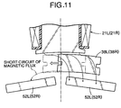
- the induction magnetic pole of the outer rotor is displaced in the circumferential direction and located between the two magnetic poles adjacent in the circumferential direction of the inner rotor, the magnetic flux from the magnetic pole of the inner rotor passes through the induction magnetic pole of the outer rotor located outside in the radial direction to short-circuit to the magnetic pole adjacent to the magnetic pole of the inner rotor in the circumferential direction. Therefore, magnetic efficiency is lowered, and performance of the rotating motor is not sufficiently exerted.
- the present invention was made in view of the above circumstances, and has a first object to simplify the structure of a rotor supporting induction magnetic poles in a motor, and improve the strength.
- the present invention has a second object to reliably fix the induction magnetic poles made of a soft magnetic body to the rotor with a simple structure.
- the present invention has a third object to improve performance by minimizing short-circuit of a magnetic flux in a magnetic machine in which an induction magnetic-pole row is arranged between first and second magnetic-pole rows.
- the patent application WO 2005/050824 discloses an electric motor with two rotors according to the introductory portion of claim 1.
- the present invention refers to a motor as defined in the independent claim 1. Further embodiments of the invention are claimed in the dependent claims 2 to 15.
- the motor comprises: an annular stator generating first and second rotating magnetic fields by first and second armatures arranged so as to surround an axis; a first rotor having first and second permanent magnet rows including first and second permanent magnets and rotatable around the axis; and a second rotor arranged between the stator and the first rotor, having first and second induction magnetic-pole rows including first and second induction magnetic poles, and rotatable around the axis.
- the first armature row and the first permanent magnet row are opposed on opposite sides in the radial direction of the first induction magnetic-pole row, respectively, and the second armature row and the second permanent magnet row are opposed on opposite sides in the radial direction of the second induction magnetic-pole row, respectively. Therefore, by controlling electricity to the first and second armatures so as to rotate the first and second rotating magnetic fields, a magnetic path is formed so as to pass through the first and second armatures, the first and second permanent magnets, and the first and second induction magnetic poles, so that one of or both the first rotor and the second rotor can be rotated.
- the phase of the magnetic pole of the first permanent magnet row and the phase of the magnetic pole of the second permanent magnet row of the first rotor are displaced from each other by a half of a predetermined pitch in the circumferential direction, and the phase of polarity of the first rotating magnetic field and the phase of the polarity of the second rotating magnetic field of the stator are displaced from each other by a half of the predetermined pitch in the circumferential direction. Therefore, the phase of the first induction magnetic pole and the phase of the second induction magnetic pole of the second rotor can be matched with each other.
- the induction magnetic poles are embedded in the second rotor in order to support the plurality of induction magnetic poles made by a soft magnetic body with the predetermined intervals in the circumferential direction in the rotor made by a weak magnetic body and rotating around the axis. Therefore, it is possible to support the induction magnetic poles at the rotor without using a dedicated fixing member such as a bolt, thereby reducing the number of parts corresponding to the number of the fixing members.
- the rotor since the rotor has a cylindrical shape and a part of the induction magnetic pole is exposed on the inner-circumferential surface of the rotor, it is possible to reduce an air gap generated between the rotor and the magnetic pole and located inside the rotor.
- the face on which the rotor and the spacer are in contact is made into a shape which limits movement of the spacer in the radial direction with respect to the rotor, it is possible to prevent detachment of the spacer due to a centrifugal force when the rotor is rotated.
- the outer-circumferential face of the spacer is covered by the ring made by a weak magnetic body, not only it is possible to more reliably prevent detachment of the spacer due to a centrifugal force when the rotor is rotated, but also it is possible to prevent bulging of the central part of the rotor in the axial direction due to the centrifugal force. Supposing that a ring is wound around the soft magnetic body, an unnecessary gap is generated on the outer-circumferential face of the soft magnetic body, but the generation of the gap can be prevented by winding the ring on the outer-circumferential face of the spacer.
- the holder since the holder is provided in order to limit movement of the induction magnetic pole in the axial direction with respect to the rotor, it is possible to prevent detachment of the induction magnetic pole from the rotor in the axial direction.
- the rotor comprises the rotor body in a bottomed cylindrical shape and the cover connected to the rotor body so as to cover the opening of the rotor body, and the rotating shafts are provided in the bottom portions of the rotor body and the cover, the rotor is supported at its opposite ends to stabilize the rotation.
- the angle formed between opposite ends in the circumferential direction of the induction magnetic poles of the induction magnetic-pole row with respect to the axis is made smaller than at least one of the machine angle corresponding to an electric angle of 180° of the magnetic pole of the first and second armature rows and the machine angle corresponding to an electric angle of 180° of the magnetic pole of the first and second permanent magnet row. Therefore, it is possible to suppress a magnetic short-circuit from being generated between the magnetic poles adjacent in the circumferential direction of the armature rows or the permanent magnet rows through the induction magnetic pole of the induction magnetic-pole row, thereby improving magnetic efficiency.
- the first rotor or the induction magnetic-pole row is moved so as to function as a motor.
- the first rotor or the induction magnetic-pole row is moved by an external force. Therefore, it is possible to generate an electromotive force at the plurality of armatures so that they function as a motor.
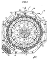
- FIGS. 1 to 17 A first embodiment of the present invention will be described based on FIGS. 1 to 17 .
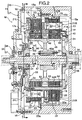
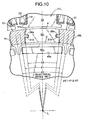
- a motor M of this embodiment comprises a casing 11 forming an octagonal cylindrical shape, which is short in a direction of an axis L, annular first and second stators 12L, 12R fixed to the inner circumference of the casing 11, a cylindrical outer rotor 13 accommodated within the first and second stators 12L, 12R and rotating around the axis L, and a cylindrical inner rotor 14 accommodated within the outer rotor 13 and rotating around the axis L.
- the outer rotor 13 and the inner rotor 14 are capable of relative rotation with respect to the fixed first and second stators 12L, 12R, and are capable of relative rotation with each other.
- the casing 11 has an octagonal bottomed cylindrical body portion 15 and an octagonal-plate-shaped lid portion 17 fixed to an opening of the body portion 15 with a plurality of bolts 16.
- a plurality of openings 15a, 17a for ventilation are formed in the body portion 15 and the lid portion 17.
- the first and second stators 12L, 12R have the same structure, and are superposed on each other while being displaced from each other in the circumferential direction.
- the structure will be described taking one of them, i.e., the first stator 12L as a representative.
- the first stator 12L has a plurality (24 pieces in the embodiment) of first armatures 21L each including a coil 20 wound around the outer circumference of a core 18 made of laminated steel plates with an insulator 19 therebetween.
- These first armatures 21L are integrated by a ring-shaped holder 22 while being connected in the circumferential direction so as to form generally annular shape.
- a flange 22a projecting in the radial direction from one end on the axis L direction of the holder 22 is fixed to a stepped portion 15b (see FIG. 2 ) on the inner face of the body portion 15 in the casing 11 by a plurality of bolts 23.
- the second stator 12R is provided with 24 pieces of second armatures 21R similarly to the first stator 12L.
- the flange 22a of the holder 22 is fixed to a stepped portion 15c (see FIG. 2 ) on the inner face of the body portion 15 in the casing 11 by a plurality of bolts 24.
- phases in the circumferential direction of the first stator 12L and the second stator 12R are displaced from each other by a half of a pitch of first and second permanent magnets 52L, 52R of the inner rotor 14 (see FIGS. 3 and 4 ).
- a three-phase alternating current is supplied from three terminals 25, 26, 27 (see FIG. 1 ) provided at the body portion 15 of the casing 11 to the first and second armatures 21L, 21R of the first and second stators 12L, 12R, thereby generating a rotating magnetic field at the first and second stators 12L, 12R.
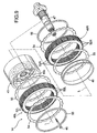
- the outer rotor 13 is a hollow member including a rotor body 31 formed by a weak magnetic body in a bottomed cylindrical shape, and a rotor cover 33 formed by a weak magnetic body into a disk shape and fixed by bolts 32 so as to cover the opening of the rotor body 31.
- a first outer rotor shaft 34 projecting from the center of the bottom portion of the rotor body 31 onto the axis L is rotatably supported by the body portion 15 of the casing 11 by a ball bearing 35.
- a second outer rotor shaft 36 projecting from the center of the rotor cover 33 onto the axis L is rotatably supported on the lid portion 17 of the casing 11 by a ball bearing 37.
- the first outer rotor shaft 34 serving as an output shaft of the outer rotor 13 penetrates the body portion 15 of the casing 11 to extend outside.
- the weak magnetic body is a material not attracted by a magnet, includes resin, wood and the like in addition to aluminum and the like, and is also called as a non-magnetic body in some cases.
- a plurality of (20 in the embodiment) slits 31a extending in parallel with the axis L are formed in the outer circumferential face of the rotor body 31 so as to communicate with the inside and outside in the radial direction.
- Each slit 31a is opened on the bottom-portion side of the rotor body 31, and closed on the opening side of the rotor body 31.
- First induction magnetic poles 38L made by a soft magnetic body, spacers 39, and second induction magnetic poles 38R made by a soft magnetic body are inserted into the slits 31a in the axis L direction from the bottom-portion side of the rotor body 31 and embedded therein.
- the first and second induction magnetic poles 38L, 38R are formed by steel plates laminated in the axis L direction.
- a pair of projections 31b, 31b projecting in a direction approaching each other are formed on the opposing inner faces of each slit 31a in the rotor body 31.
- a pair of recesses 38a, 38a; 39a, 39a slidably engaged with the pair of projections 31b, 31b are formed in the outer faces of the first and second induction magnetic poles 38L, 38R and the spacer 39 brought into contact with the inner face of the slits 31a.
- the front end of the first induction magnetic pole 38L is brought into contact with a stopper 31c (see FIG. 6 ) at the front end of the slit 31a so as to limit their movement.
- a stopper 31c see FIG. 6
- one of a plurality of elastic claws 41a projecting in the axis L direction from an annular holder 41 fixed to the bottom portion of the rotor body 31 by bolts 40 is brought into resilient contact with the rear end of the second induction magnetic pole 38R.
- the first and second induction magnetic poles 38L, 38R and the spacer 39 inserted into the slit 31a are retained by the stopper 31c and the elastic claw 41a of the holder 41, whereby they are prevented from being pulled out in the axis L direction and rattling is prevented from occurring.
- a first resolver 42 for detecting a rotating position of the outer rotor 13 is provided so as to surround the second outer rotor shaft 36 of the outer rotor 13.
- the first resolver 42 comprises a resolver rotor 43 fixed to the outer circumference of the second outer rotor shaft 36, and a resolver stator 44 fixed to the lid portion 17 of the casing 11 so as to surround the periphery of the resolver rotor 43.
- the inner rotor 14 comprises a rotor body 45 formed into a cylindrical shape, an inner rotor shaft 47 penetrating a hub 45a of the rotor body 45 and fixed by a bolt 46, annular first and second rotor cores 48L, 48R including laminated steel plates and fitted on the outer circumference of the rotor body 45, and an annular spacer 49 fitted on the outer circumference of the rotor body 45.
- One end of the inner rotor shaft 47 is rotatably supported on the axis L by a ball bearing 50 within the first outer rotor shaft 34.
- the other end of the inner rotor shaft 47 is rotatably supported by a ball bearing 51 within the second outer rotor shaft 36, and penetrates the second outer rotor shaft 36 and the lid portion 17 of the casing 11 to extend outside the casing 11 so as to serve as an output shaft of the inner rotor 14.
- the first and second rotor cores 48L, 48R fitted on the outer circumference of the rotor body 45 have the same structure, and are provided with a plurality of (20 pieces in the embodiment) permanent magnet supporting holes 48a along the outer-circumferential face (see FIGS. 3 and 4 ), into which the first and second permanent magnets 52L, 52R are press-fitted in the axis L direction.
- the polarity of the adjacent first permanent magnets 52L of the first rotor core 48L are alternately reversed, the polarity of the adjacent second permanent magnets 52R of the second rotor core 48R are alternately reversed, and the phase in the circumferential direction of the first permanent magnets 52L in the first rotor core 48L and the phase in the circumferential direction of the second permanent magnets 52R in the second rotor core 48R are displaced from each other by a half of the pitch (see FIGS. 3 and 4 ).
- the spacer 49 made of the weak magnetic body is fitted in a central portion in the axis L direction in the outer circumference of the rotor body 45; a pair of inner permanent-magnet support plates 53, 53 for retaining the first and second permanent magnets 52L, 52R are fitted on the outside, respectively; the first and second rotor cores 48L, 48R are fitted on the outside, respectively; a pair of outer permanent-magnet support plates 54, 54 retaining the first and second permanent magnets 52L, 52R are fitted on the outside, respectively; and a pair of stopper rings 55, 55 are fixed by press-fitting on the outside, respectively.
- a second resolver 56 for detecting a rotational position of the inner rotor 14 is provided so as to surround the inner rotor shaft 47.
- the second resolver 56 comprises a resolver rotor 57 fixed to the outer circumference of the inner rotor shaft 47, and a resolver stator 58 fixed to the lid portion 17 of the casing 11 so as to surround the periphery of the resolver rotor 57.
- the inner circumferential face of the first armatures 21L of the first stator 12L is opposed through a slight air gap ⁇ to the outer circumference face of the first induction magnetic poles 38L exposed on the outer circumferential face of the outer rotor 13, and the outer circumferential face of the first rotor core 48L of the inner rotor 14 is opposed through a slight air gap ⁇ to the inner circumferential face of the first induction magnetic poles 38L exposed on the inner circumferential face of the outer rotor 13.
- the inner circumferential face of the second armatures 21R of the second stator 12R is opposed through a slight air gap ⁇ to the outer circumference face of the second induction magnetic poles 38R exposed on the outer circumferential face of the outer rotor 13
- the outer circumferential face of the second rotor core 48R of the inner rotor 14 is opposed through a slight air gap ⁇ to the inner circumferential face of the second induction magnetic poles 38R exposed on the inner circumferential face of the outer rotor 13.
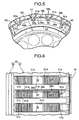
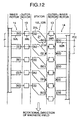
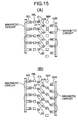
- FIG. 12 schematically shows a state where the motor M is extended in the circumferential direction.
- the first and second permanent magnets 52L, 52R of the inner rotor 14 are shown, respectively.
- the first and second permanent magnets 52L, 52R are arranged in the circumferential direction (vertical direction in FIG. 12 ) with N pole and S pole provided alternately at a predetermined pitch P.
- the first permanent magnets 52L and the second permanent magnets 52R are arranged while displaced from each other by only a half of the predetermined pitch P, that is, a half pitch P/2.
- virtual permanent magnets 21 corresponding to the first and second armatures 21L, 21R of the first and second stators 12L, 12R are arranged in the circumferential direction with the predetermined pitch P.
- the number of the first and second armatures 21L, 21R of the first and second stators 12L, 12R is 24, respectively, and the number of the first and second permanent magnets 52L, 52R of the inner rotor 14 is 20, respectively.
- the pitch of the first and the second armatures 21L, 21R does not match the pitch P of the first and second permanent magnets 52L, 52R of the inner rotor 14.
- first and second armatures 21L, 21R form rotating magnetic fields, respectively, the first and second armatures 21L, 21R can be replaced by 20 pieces of the virtual permanent magnets 21 arranged with the pitch P and rotated in the circumferential direction.
- the first and second armatures 21L, 21R are hereinafter called as first and second virtual magnetic poles 21L, 21R of the virtual permanent magnets 21.
- the polarity of the first and second virtual magnetic poles 21L, 21R of the virtual permanent magnets 21 adjacent in the circumferential direction are alternately reversed, and the first virtual magnetic poles 21L and the second virtual magnetic poles 21R of the virtual permanent magnets 21 are displaced from each other in the circumferential direction by the half pitch P/2.
- the first and second induction magnetic poles 38L, 38R of the outer rotor 13 are arranged between the first and second permanent magnets 52L, 52R and the virtual permanent magnets 21.
- the first and second induction magnetic poles 38L, 38R are arranged with the pitch P in the circumferential direction, and aligned with the first induction magnetic poles 38L and the second induction magnetic poles 38R in the axis L direction.
- the first induction magnetic poles 38L are aligned with respect to the opposing first permanent magnets 52L and the first virtual magnetic poles 21L of the virtual permanent magnets 21, and the second induction magnetic poles 38R are displaced by the half pitch P/2 with respect to the opposing second virtual magnetic poles 21R and the second permanent magnets 52R.
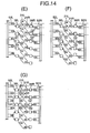
- the virtual permanent magnets 21 are rotated downward in FIG. 13(A) .
- the polarity of the first virtual magnetic poles 21L of the virtual permanent magnets 21 is different from the polarity of the opposing first permanent magnets 52L, and the polarity of the second virtual magnetic poles 21R of the virtual permanent magnets 21 is the same as the polarity of the opposing second permanent magnets 52R.
- the first induction magnetic poles 38L are arranged between the first permanent magnets 52L and the first virtual magnetic poles 21L of the virtual permanent magnets 21, the first induction magnetic poles 38L are magnetized by the first permanent magnets 52L and the first virtual magnetic poles 21L, whereby a first magnetic line G1 is generated between the first permanent magnets 52L, the first induction magnetic poles 38L and the first virtual magnetic poles 21L.
- the second induction magnetic poles 38R are arranged between the second virtual magnetic poles 21R and the second permanent magnets 52R, the second induction magnetic poles 38R are magnetized by the second virtual magnetic poles 21R and the second permanent magnets 52R, whereby a second magnetic line G2 is generated between the second virtual magnetic poles 21R, the second induction magnetic poles 38R and the second permanent magnets 52R.
- the first magnetic line G1 is generated so as to connect together the first permanent magnets 52L, the first induction magnetic poles 38L, and the first virtual magnetic poles 21L
- the second magnetic line G2 is generated so as to connect each two second virtual magnetic poles 21R adjacent in the circumferential direction and the second induction magnetic poles 38R located therebetween and to connect each two second permanent magnets 52R adjacent in the circumferential direction and the second induction magnetic poles 38R located therebetween.
- a magnetic force for rotation in the circumferential direction does not act on the first induction magnetic poles 38L, since the first magnetic line G1 is linear.
- a bending degree and a total magnetic flux of the two second magnetic lines G2 are equal to each other between each two second virtual magnetic poles 21R adjacent in the circumferential direction and the second induction magnetic poles 38R, and the bending degree and the total magnetic flux amount of the two second magnetic lines G2 are also equal to each other between each two second permanent magnets 52R adjacent in the circumferential direction and the second induction magnetic poles 38R, thereby establishing a balance.
- a magnetic force for rotation in the circumferential direction does not act on the second induction magnetic poles 38R, either.
- the first induction magnetic poles 38L are driven by a relatively large driving force in the rotating direction of the virtual permanent magnets 21, that is, in the magnetic field rotating direction.
- the outer rotor 13 is rotated in the magnetic field rotating direction.
- the bending degree of the second magnetic line G2 is large, the total magnetic flux amount is small, and thus a relatively small magnetic force acts on the second induction magnetic poles 38R, whereby the second induction magnetic poles 38R are driven by a relatively small driving force in the magnetic field rotating direction.
- the outer rotor 13 is rotated in the magnetic field rotating direction.
- the bending degree of the first magnetic line G1 becomes larger, the total magnetic flux amount becomes smaller, and thus the magnetic force acting on the first induction magnetic poles 38L is gradually weakened, whereby the driving force driving the first induction magnetic poles 38L in the magnetic field rotating direction is gradually reduced.
- the bending degree of the second magnetic line G2 becomes smaller, the total magnetic flux amount becomes larger, and thus the magnetic force acting on the second induction magnetic poles 38R becomes gradually stronger, whereby the driving force driving the second induction magnetic poles 38R in the magnetic field rotating direction is gradually increased.
- the magnetic force acting on the second induction magnetic poles 38R is weakened since the total magnetic flux amount is decreased although the bending degree of the second magnetic line G2 is increased, so that the driving force acting on the second induction magnetic poles 38R becomes smaller.
- the first and second induction magnetic poles 38L, 38R are rotated only by the half pitch P/2. Therefore, the outer rotor 13 is rotated at a speed of 1/2 of the rotating speed of the rotating magnetic field of the first and second stators 12L, 12R. This is because the first and the second induction magnetic poles 38L, 38R are rotated by the action of the magnetic force caused by the first and second magnetic lines G1, G2, while being kept located between the first permanent magnets 52L and the first virtual magnetic poles 21L connected by the first magnetic line G1 and between the second permanent magnets 52R and the second virtual magnetic poles 21R connected by the second magnetic line G2.
- the second permanent magnets 52R are driven together with the first permanent magnets 52L in the rotating direction of the virtual permanent magnets 21, that is, a direction (upper side in FIGS. 16 (A) to 16 (D) ) opposite from the magnetic field rotating direction, and rotated toward a position shown in FIG. 16(C) .
- the inner rotor 14 is rotated in a direction opposite from the magnetic field rotating direction.
- the virtual permanent magnets 21 are rotated toward a position shown in FIG. 16(D) .
- the bending degree of the second magnetic line G2 between the second induction magnetic poles 38R and the second permanent magnets 52R becomes smaller, but the total magnetic flux amount of the second magnetic line G2 becomes larger as the virtual permanent magnets 21 further approaches the second induction magnetic poles 38R.
- the magnetic force to bring the second permanent magnets 52R closer to the second induction magnetic poles 38R acts on the second permanent magnets 52R, whereby the second permanent magnets 52R are driven together with the first permanent magnets 52L in a direction opposite from the magnetic field rotating direction.
- the first permanent magnets 52L is rotated in a direction opposite from the magnetic field rotating direction, the first magnetic line G1 between the first permanent magnets 52L and the first induction magnetic poles 38L is bent, and thus a magnetic force to bring the first permanent magnets 52L closer to the first induction magnetic poles 38L acts on the first permanent magnets 52L.
- the magnetic force caused by the first magnetic line G1 is weaker than the magnetic force caused by the second magnetic line G2, since the bending degree of the first magnetic line G1 is smaller than the second magnetic line G2.
- the second permanent magnets 52R are driven together with the first permanent magnets 52L in a direction opposite from the magnetic field rotating direction by the magnetic force corresponding to a difference between the two magnetic forces.
- the first permanent magnets 52L are driven together with the second permanent magnets 52R in a direction opposite from the magnetic field rotating direction by the magnetic force corresponding to a difference between the magnetic force caused by the first magnetic line G1 between the first permanent magnets 52L and the first induction magnetic poles 38L and the magnetic force caused by the second magnetic line G2 between the second permanent magnets 52R and the second induction magnetic poles 38R.
- the magnetic force caused by the second magnetic line G2 hardly acts so as to bring the second permanent magnets 52R closer to the second induction magnetic poles 38R
- the first permanent magnets 52L are driven together with the second permanent magnets 52R by the magnetic force caused by the first magnetic line G1.
- the magnetic force caused by the first magnetic line G1 between the first permanent magnets 52L and the first induction magnetic poles 38L, the magnetic force caused by the second magnetic line G2 between the second permanent magnets 52R and the second induction magnetic poles 38R, and the magnetic force corresponding to a difference between these magnetic forces alternately act on the first and second permanent magnets 52L, 52R, that is, the inner rotor 14, whereby the inner rotor 14 is rotated in a direction opposite from the magnetic field rotating direction.
- the magnetic forces, that is, the driving forces act on the inner rotor 14, thereby making the torque of the inner rotor 14 constant.
- the inner rotor 14 is rotated at a speed equal to those of the first and second rotating magnetic fields. This is because the first and the second permanents magnets 52L, 52R are rotated, while the first and second induction magnetic poles 38L, 38R are kept located between the first permanent magnets 52L and the first virtual magnetic poles 21L and between the second permanent magnets 52R and the second virtual magnetic poles 21R, respectively, by the action of the magnetic forces caused by the first and second magnetic lines G1, G2.
- the numbers of the first virtual magnetic poles 21L, the first permanent magnets 52L and the first induction magnetic poles 38L are set equal to each other, and the numbers of the second virtual magnetic poles 21R, the second permanent magnets 52R and the second induction magnetic poles 38R are set equal to each other, it is possible to obtain a sufficient torque of the motor M whichever the inner rotor 14 or the outer rotor 13 is driven.
- the dimension of the motor M in the axis L direction can be reduced as compared with the case where the outer rotor 13 and the inner rotor 14 are rotatably supported directly by the casing 11, respectively.
- the ball bearings 50, 51 cannot be arranged between the pair of ball bearings 35, 37 of the outer rotor 13 when the inner rotor 14 is directly supported by the casing 11 through the pair of ball bearings 50, 51, and they are required to be arranged in a position outside in the axis L direction of the pair of ball bearings 35, 37 of the outer rotor 13.
- first resolver 42 for detecting the rotational position of the outer rotor 13 and the second resolver 56 for detecting the rotational position of the inner rotor 14 are arranged together in a concentrated manner on one end side in the axis L direction, that is, on the lid portion 17 side of the casing 11, it is possible to perform the operation, such as inspection, repair, assembling and replacement, of the first and second resolvers 42, 56 at the same time only by removing the lid portion 17, thereby greatly improving convenience. Moreover, handling of harnesses of the first and second resolvers 42, 56 is facilitated.
- the air gap ⁇ of the outer rotor 13 with respect to the first and second stators 12L, 12R and the air gap ⁇ of the inner rotor 14 with respect to the first and second cores 48L, 48R can be minimized, thereby improving the magnetic efficiency.
- first induction magnetic poles 38L and the second induction magnetic poles 38R are arranged with the same phase in the circumferential direction, not only the structure of the rotor body 31 of the outer rotor 13 supporting the first and second induction magnetic poles 38L, 38R is simplified as compared with the arrangement of the first and second induction magnetic poles 38L, 38R with the different phases in the circumferential direction but also strength of the rotor body 31 can be improved.
- the support of the first and second induction magnetic poles 38L, 38R and the spacers 39 with respect to the rotor body 31 is established by inserting the first and second induction magnetic poles 38L, 38R and the recesses 38a, 38a; 39a, 39b of the spacer 39 while sliding in the axis L direction with respect to the projections 31b, 31b of the slit 31a in the rotor body 31, not only the assembling work is facilitated but also dedicated fixing means such as bolts are not needed, which contributes to reduction in the number of parts and simplification of the structure. Moreover, it is possible to reliably prevent detachment of the first and second induction magnetic poles 38L, 38R and the spacer 39 in the radial direction by a centrifugal force generated by rotation of the outer rotor 13.
- the recesses 38a are formed in the first and second induction magnetic poles 38L, 38R, unnecessary portions of the first and second induction magnetic poles 38L, 38R are eliminated by the recesses 38a, thereby reducing eddy loss and hysteresis loss.
- an angle ⁇ 2 formed by two straight lines drawn from the axis L to opposite ends in the circumferential direction of the first and second induction magnetic poles 38L, 38R is set smaller than a mechanical angle ⁇ 0 corresponding to an electric angle 180° of the first and second permanent magnets 52L, 52R.
- ⁇ 1 is an angle formed by two straight lines drawn from the axis L to opposite ends in the circumferential direction of the first and second permanent magnets 52L, 52R, and the relationship among the three angles is ⁇ 0 > ⁇ 1 ⁇ ⁇ 2.
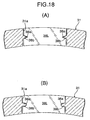
- the shape of the recesses 38a, 39a of the first and second induction magnetic poles 38L, 38R and the spacer 39, as well as the shape of the projections 31b of the slits 31a in the rotor body 31 are square, but the same effects can be achieved also by a triangular shape as shown in FIG. 18 (A) or an U-shape as shown in FIG. 18(B) .
- first and second induction magnetic poles 38L, 38R can be reliably supported by reversing the positional relationship among the recesses 38a, 39a and the projections 31b, forming the projections on the side of the first and second induction magnetic poles 38L, 38R and the spacer 39, and forming the recesses on the side of the slits 31a.
- the recesses 38a are formed on the side of the first and second induction magnetic poles 38L, 38R as in the embodiments, eddy loss and hysteresis loss can be reduced as compared with the case where the recesses are formed on the side of the slits 31a.
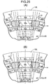
- grooves 39b extending in the circumferential direction are formed in the surface of the spacers 39 of the outer rotor 13
- grooves 31d leading to the grooves 39b of the spacers 39 are formed in the outer circumferential face of the rotor body 31 of the outer rotor 13
- a ring 59 made of a weak magnetic body is fitted in the grooves 39b, 31d.
- the first permanent magnet 52L or the second permanent magnet 52R constituting a single magnetic pole of the inner rotor 14 is divided into two parts.
- the two permanent magnets in order for the two permanent magnets to constitute a single magnetic pole, it is necessary for the polarities of the two permanent magnets to match with each other.
- ⁇ 0 corresponding to the electric angle 180° of the magnetic pole in the inner rotor 14 is defined as an angle formed by two radial lines passing between adjacent pairs, when the two permanent magnets 52L, 52L (or 52R, 52R) constituting a single magnetic pole are made as a pair.
- the present invention is applied to the rotating-type motor M, but in the fifth example, linear-motion type motor M (so-called linear motor) is shown.
- a linear induction magnetic-pole row formed by the first and second induction magnetic poles 38L, 38R is arranged between a linear first magnetic-pole row consisting of the first and second armatures 21L, 21R and a linear second magnetic-pole row consisting of the first and second permanent magnets 52L, 52R.
- electricity is supplied to the first and second armatures 21L, 21R so as to generate a moving magnetic field at the first magnetic-pole row, one of or both the second magnetic-pole row and the induction magnetic-pole row can be moved in the linear direction.
- a distance L2 between opposite ends in the linear direction between the first and second induction magnetic poles 38L, 38R of the induction magnetic-pole row is set smaller than a distance L0 corresponding to the electric angle 180° of the first and second permanent magnets 52L, 52R of the second magnetic-pole row, whereby it is possible to suppress a magnetic short-circuit from being generated between the first permanent magnets 52L (or the second permanent magnets 52R) adjacent in the linear direction of the second magnetic-pole row through the first induction magnetic poles 38L (or second induction magnetic poles 38R) of the induction magnetic-pole row, thereby improving magnetic efficiency.
- FIGS. 24 and 25 Next, a sixth example not being part of the present invention will be described based on FIGS. 24 and 25 .
- a magnetic gear in which the first and second stators 12L, 12R are provided with first and second permanent magnets 60L, 60R instead of the first and second armatures 21L, 21R.
- a driving force can be transmitted between the first and second stators 12L, 12R and the outer rotor 13; if the outer rotor 13 is fixed, the driving force can be transmitted between the first and second stators 12L, 12R and the inner rotor 14; and if the three are made rotatable, they can function as a differential device.
- ⁇ 0 corresponding to the electric angle 180° of the first and second permanent magnets 52L, 52R of the inner rotor 14 is set so that a relationship of 90 ⁇ ⁇ 1 ⁇ ⁇ 2 is established with respect to an angle ⁇ 2 formed by two straight lines drawn from the axis L to opposite ends of the first and second induction magnetic poles 38L, 38R in the circumferential direction, and an angle ⁇ 1 formed by two straight lines drawn from the axis L to opposite ends of the first and second permanent magnets 52L, 52R in the circumferential direction have.
- ⁇ 0 corresponding to the electric angle 180° of the first and second permanent magnets 60L, 60R of the first and second stators 12L, 12R is set so that a relationship of ⁇ 0 ⁇ ⁇ 1 ⁇ ⁇ 2 is established with respect to the angle ⁇ 2 formed by two straight lines drawn from the axis L to opposite ends of the first and second induction magnetic poles 38L, 38R in the circumferential direction, and the angle ⁇ 1 formed by two straight lines drawn from the axis L to opposite ends of the first and second permanent magnets 60L, 60R in the circumferential direction.
- the motor M is illustrated in the embodiments, but the present invention is applicable to a motor which generates an electromotive force at a stator by fixing one of the outer-rotor and the inner rotor and rotating the other.
- the armatures 21L, 21R are provided at the stators 12L, 12R arranged outside in the radial direction, and the permanent magnets 52L, 52R are provided at the inner rotor 14 arranged inside in the radial direction, but their positional relationship may be reversed so that the stator having the armature 21L, 21R is arranged inside in the radial direction and the outer rotor having the permanent magnets 52L, 52R is arranged outside in the radial direction.
- the stators 12L, 12R, the outer rotor 13 and the inner rotor 14 are arranged in the radial direction (radial arrangement), but they may be arranged in the axis L direction. That is, the stators having the armatures and the rotors having the permanent magnets may be arranged on opposite sides in the axis L direction of the rotor having the induction magnetic poles (axial arrangement). This arrangement is not part of the claimed invention.
- stators 12L, 12R are wound in the concentrated manner in the embodiments, but the winding may be a distributed type.
- the polar logarithms of the first and second stators 12L, 12R, the outer rotor 13 and the inner rotor 14 are not limited to those in the embodiments, and can be appropriately changed.
Abstract
Applications Claiming Priority (5)
| Application Number | Priority Date | Filing Date | Title |
|---|---|---|---|
| JP2007026423A JP2008193823A (ja) | 2007-02-06 | 2007-02-06 | ロータ構造 |
| JP2007026422 | 2007-02-06 | ||
| JP2007026424 | 2007-02-06 | ||
| JP2007316189A JP4648378B2 (ja) | 2007-02-06 | 2007-12-06 | 電動機 |
| PCT/JP2008/050865 WO2008096600A1 (ja) | 2007-02-06 | 2008-01-23 | 電動機、ロータ構造および磁気機械 |
Publications (3)
| Publication Number | Publication Date |
|---|---|
| EP2110933A1 EP2110933A1 (en) | 2009-10-21 |
| EP2110933A4 EP2110933A4 (en) | 2010-03-24 |
| EP2110933B1 true EP2110933B1 (en) | 2012-08-01 |
Family
ID=40943393
Family Applications (1)
| Application Number | Title | Priority Date | Filing Date |
|---|---|---|---|
| EP08703706A Not-in-force EP2110933B1 (en) | 2007-02-06 | 2008-01-23 | Motor, rotor structure and magnetic machine |
Country Status (8)
| Country | Link |
|---|---|
| US (1) | US20080238232A1 (ja) |
| EP (1) | EP2110933B1 (ja) |
| KR (1) | KR101121271B1 (ja) |
| AU (1) | AU2008212433B2 (ja) |
| BR (1) | BRPI0807008A2 (ja) |
| CA (1) | CA2677411A1 (ja) |
| MX (1) | MX2009008346A (ja) |
| WO (1) | WO2008096600A1 (ja) |
Families Citing this family (21)
| Publication number | Priority date | Publication date | Assignee | Title |
|---|---|---|---|---|
| CN101897108B (zh) * | 2007-12-26 | 2013-04-10 | 本田技研工业株式会社 | 电动机以及旋转电机用转子 |
| GB0810097D0 (en) * | 2008-06-03 | 2008-07-09 | Magnomatics Ltd | Magnetic gear |
| GB0808524D0 (en) * | 2008-05-12 | 2008-06-18 | Magnomatics Ltd | Magnetic pole-piece structure |
| IT1392883B1 (it) | 2008-09-03 | 2012-04-02 | Lenzi | Metodo per l'assemblaggio del rotore di una macchina elettrica rotante |
| EP2479871B1 (en) * | 2011-01-19 | 2016-06-15 | GE Energy Power Conversion Technology Limited | Electrical machines |
| JP5350438B2 (ja) * | 2011-06-29 | 2013-11-27 | 株式会社日立製作所 | 磁気式歯車機構 |
| JP5772322B2 (ja) * | 2011-07-13 | 2015-09-02 | 株式会社豊田中央研究所 | 変速機構付き回転電機 |
| RU2475926C1 (ru) * | 2011-07-29 | 2013-02-20 | Открытое акционерное общество "Научно-производственная корпорация "Космические системы мониторинга, информационно-управляющие и электромеханические комплексы имени А.Г. Иосифьяна" (ОАО "Корпорация "ВНИИЭМ") | Роторная система магнитоэлектрической машины |
| ES2439550T3 (es) * | 2011-08-01 | 2014-01-23 | Siemens Aktiengesellschaft | Aparato de carga de imán |
| JP5808852B2 (ja) * | 2012-03-30 | 2015-11-10 | 本田技研工業株式会社 | 回転電機 |
| CN102842974B (zh) | 2012-08-03 | 2015-06-03 | 埃塞克科技有限公司 | 横向磁通发电机 |
| US9559559B2 (en) | 2012-09-24 | 2017-01-31 | Eocycle Technologies Inc. | Transverse flux electrical machine stator with stator skew and assembly thereof |
| CA2829812A1 (en) | 2012-10-17 | 2014-04-17 | Eocycle Technologies Inc. | Transverse flux electrical machine rotor |
| JP6195989B2 (ja) * | 2014-06-17 | 2017-09-13 | 三菱電機株式会社 | 圧縮機、冷凍サイクル装置、および空気調和機 |
| GB2545154B (en) * | 2015-08-24 | 2021-12-01 | Magnomatics Ltd | Magnetically geared apparatus and a pole piece for such apparatus |
| CN106921234A (zh) * | 2017-05-16 | 2017-07-04 | 深圳市赫瑞科技有限公司 | 一种磁齿轮外转子安装结构 |
| UA124412C2 (uk) | 2017-12-22 | 2021-09-15 | Євгеній Віталійович Мушинський | Контрроторний синхронний електромеханічний перетворювач |
| US11522436B2 (en) | 2019-10-15 | 2022-12-06 | Darrell Schmidt Enterprises, Inc. | Permanently magnetized enhanced generator |
| WO2021076428A1 (en) | 2019-10-15 | 2021-04-22 | Darrell Schmidt Enterprises, Inc. | Magnetic coupler |
| JP7378592B2 (ja) * | 2020-04-16 | 2023-11-13 | 三菱電機株式会社 | 回転電機 |
| US11689088B2 (en) | 2020-08-12 | 2023-06-27 | Robert Willoughby Garrett, IV | Movable permanent magnet stator electric motor |
Citations (1)
| Publication number | Priority date | Publication date | Assignee | Title |
|---|---|---|---|---|
| EP2015428A1 (en) * | 2006-08-09 | 2009-01-14 | HONDA MOTOR CO., Ltd. | Motor |
Family Cites Families (27)
| Publication number | Priority date | Publication date | Assignee | Title |
|---|---|---|---|---|
| JPH04331445A (ja) * | 1991-05-01 | 1992-11-19 | Honda Motor Co Ltd | 誘導モータ |
| JPH0746807A (ja) * | 1993-05-21 | 1995-02-14 | Toshiba Corp | 回転電機の回転子 |
| JP3427511B2 (ja) | 1994-10-11 | 2003-07-22 | 株式会社デンソー | 二軸出力型電動機 |
| JP3190558B2 (ja) * | 1995-12-25 | 2001-07-23 | 三菱電機株式会社 | かご形誘導機の回転子の製造方法 |
| JP3051340B2 (ja) * | 1996-06-18 | 2000-06-12 | オークマ株式会社 | 同期電動機 |
| KR19990065127A (ko) * | 1998-01-08 | 1999-08-05 | 구자홍 | 매립 영구자석 동기전동기의 회전자 |
| JPH11341757A (ja) | 1998-05-21 | 1999-12-10 | Toyota Motor Corp | 電動機および動力伝達装置並びにハイブリッド車両 |
| US6274960B1 (en) * | 1998-09-29 | 2001-08-14 | Kabushiki Kaisha Toshiba | Reluctance type rotating machine with permanent magnets |
| US6590312B1 (en) * | 1999-11-18 | 2003-07-08 | Denso Corporation | Rotary electric machine having a permanent magnet stator and permanent magnet rotor |
| JP4269544B2 (ja) * | 2000-09-14 | 2009-05-27 | 株式会社デンソー | 複数ロータ型同期機 |
| JP2002122203A (ja) * | 2000-10-17 | 2002-04-26 | Minebea Co Ltd | リニアアクチュエータ |
| JP2002136094A (ja) * | 2000-10-30 | 2002-05-10 | Minebea Co Ltd | ステッピングモータ |
| US6774521B2 (en) * | 2001-05-16 | 2004-08-10 | Koyo Seiko Co., Ltd. | Brushless DC motor |
| US7064466B2 (en) * | 2001-11-27 | 2006-06-20 | Denso Corporation | Brushless rotary electric machine having tandem rotary cores |
| JP3724416B2 (ja) * | 2001-11-27 | 2005-12-07 | 株式会社デンソー | 軸方向分割混成磁極型ブラシレス回転電機 |
| GB0208565D0 (en) * | 2002-04-13 | 2002-05-22 | Rolls Royce Plc | A compact electrical machine |
| AU2003245151B2 (en) * | 2002-07-10 | 2008-11-13 | Danfoss A/S | Device to relieve thrust load in a rotor-bearing system using permanent magnets |
| JP4318959B2 (ja) * | 2003-05-21 | 2009-08-26 | 本田技研工業株式会社 | 永久磁石式回転子およびブラシレスモータ |
| US6924574B2 (en) * | 2003-05-30 | 2005-08-02 | Wisconsin Alumni Research Foundation | Dual-rotor, radial-flux, toroidally-wound, permanent-magnet machine |
| DE10354604B4 (de) * | 2003-11-21 | 2016-10-13 | Gesellschaft für Aufladetechnik und Spindelbau mbH | Stufenlos schaltbares, magnetodynamisches Getriebe |
| JP4069859B2 (ja) * | 2003-12-15 | 2008-04-02 | 日産自動車株式会社 | 回転電機の構造 |
| US7400077B2 (en) * | 2004-03-23 | 2008-07-15 | Electric Motor Development, Inc. | Electric motor having multiple armatures |
| JP4274473B2 (ja) * | 2004-06-14 | 2009-06-10 | ミネベア株式会社 | アクチュエータ |
| US7692357B2 (en) * | 2004-12-16 | 2010-04-06 | General Electric Company | Electrical machines and assemblies including a yokeless stator with modular lamination stacks |
| JP4508895B2 (ja) | 2005-02-02 | 2010-07-21 | 株式会社オーディオテクニカ | ハンギングマイクロホン |
| KR100652596B1 (ko) * | 2005-04-11 | 2006-12-01 | 엘지전자 주식회사 | 이중자석 하이브리드 유도 전동기 |
| JP4260799B2 (ja) * | 2005-12-02 | 2009-04-30 | 本田技研工業株式会社 | 電動機および電動機の駆動方法 |
-
2008
- 2008-01-23 KR KR1020097017237A patent/KR101121271B1/ko not_active IP Right Cessation
- 2008-01-23 AU AU2008212433A patent/AU2008212433B2/en not_active Ceased
- 2008-01-23 BR BRPI0807008-3A patent/BRPI0807008A2/pt not_active IP Right Cessation
- 2008-01-23 EP EP08703706A patent/EP2110933B1/en not_active Not-in-force
- 2008-01-23 WO PCT/JP2008/050865 patent/WO2008096600A1/ja active Application Filing
- 2008-01-23 MX MX2009008346A patent/MX2009008346A/es active IP Right Grant
- 2008-01-23 CA CA002677411A patent/CA2677411A1/en not_active Abandoned
- 2008-02-06 US US12/068,444 patent/US20080238232A1/en not_active Abandoned
Patent Citations (1)
| Publication number | Priority date | Publication date | Assignee | Title |
|---|---|---|---|---|
| EP2015428A1 (en) * | 2006-08-09 | 2009-01-14 | HONDA MOTOR CO., Ltd. | Motor |
Also Published As
| Publication number | Publication date |
|---|---|
| AU2008212433B2 (en) | 2011-08-11 |
| EP2110933A4 (en) | 2010-03-24 |
| WO2008096600A1 (ja) | 2008-08-14 |
| KR20090104869A (ko) | 2009-10-06 |
| BRPI0807008A2 (pt) | 2014-04-22 |
| KR101121271B1 (ko) | 2012-03-26 |
| EP2110933A1 (en) | 2009-10-21 |
| MX2009008346A (es) | 2009-08-20 |
| US20080238232A1 (en) | 2008-10-02 |
| AU2008212433A1 (en) | 2008-08-14 |
| CA2677411A1 (en) | 2008-08-14 |
Similar Documents
| Publication | Publication Date | Title |
|---|---|---|
| EP2110933B1 (en) | Motor, rotor structure and magnetic machine | |
| EP2226924B1 (en) | Motor and rotor for dynamo-electric machine | |
| EP0558746B1 (en) | Rotor of brushless motor | |
| CN101779366B (zh) | 轴向间隙型电动机 | |
| EP1990895B1 (en) | Stress distributing permanent magnet rotor geometry for electric machines | |
| WO2015146210A1 (ja) | 永久磁石式回転電機及びその製造方法 | |
| EP2141784B1 (en) | Rotor for rotating machine | |
| JP2009509490A (ja) | 電気機械の永久磁石励磁一次側磁極部材のための歯モジュール | |
| CN116057820A (zh) | 旋转电机以及定子的制造方法 | |
| JP3610961B2 (ja) | 回転電機及びその回転電機を用いたハイブリッド車両 | |
| CN101589537A (zh) | 电动机、转子构造及磁设备 | |
| JP5691451B2 (ja) | 回転電機用ロータ | |
| RU2435282C2 (ru) | Двигатель, структура ротора и магнитная машина | |
| EP4096062A1 (en) | Stator and rotating electrical machine using the same | |
| JP4801824B2 (ja) | 磁気機械 | |
| JP2008193823A (ja) | ロータ構造 | |
| JP4680980B2 (ja) | 電動機 | |
| JP4482900B2 (ja) | アキシャルギャップ型モータ | |
| WO2023118983A1 (en) | Reduction of cogging torque in two-stator permanent magnet generators with an intermediate rotor radial flux. | |
| JP4648378B2 (ja) | 電動機 | |
| JP4767997B2 (ja) | 回転電機用ロータおよび電動機 | |
| JP2008289227A (ja) | 回転電機用ロータ | |
| JP4691087B2 (ja) | 電動機 | |
| CN117220428A (zh) | 具有带轴向磁通磁体板的径向辐条式转子的转矩常数可变的电机及其方法 | |
| JPH0426350A (ja) | ブラシレスモータ |
Legal Events
| Date | Code | Title | Description |
|---|---|---|---|
| PUAI | Public reference made under article 153(3) epc to a published international application that has entered the european phase |
Free format text: ORIGINAL CODE: 0009012 |
|
| 17P | Request for examination filed |
Effective date: 20090806 |
|
| AK | Designated contracting states |
Kind code of ref document: A1 Designated state(s): AT BE BG CH CY CZ DE DK EE ES FI FR GB GR HR HU IE IS IT LI LT LU LV MC MT NL NO PL PT RO SE SI SK TR |
|
| A4 | Supplementary search report drawn up and despatched |
Effective date: 20100218 |
|
| 17Q | First examination report despatched |
Effective date: 20100303 |
|
| DAX | Request for extension of the european patent (deleted) | ||
| RTI1 | Title (correction) |
Free format text: MOTOR, ROTOR STRUCTURE AND MAGNETIC MACHINE |
|
| GRAP | Despatch of communication of intention to grant a patent |
Free format text: ORIGINAL CODE: EPIDOSNIGR1 |
|
| GRAS | Grant fee paid |
Free format text: ORIGINAL CODE: EPIDOSNIGR3 |
|
| GRAA | (expected) grant |
Free format text: ORIGINAL CODE: 0009210 |
|
| AK | Designated contracting states |
Kind code of ref document: B1 Designated state(s): AT BE BG CH CY CZ DE DK EE ES FI FR GB GR HR HU IE IS IT LI LT LU LV MC MT NL NO PL PT RO SE SI SK TR |
|
| REG | Reference to a national code |
Ref country code: GB Ref legal event code: FG4D |
|
| REG | Reference to a national code |
Ref country code: CH Ref legal event code: EP Ref country code: AT Ref legal event code: REF Ref document number: 569100 Country of ref document: AT Kind code of ref document: T Effective date: 20120815 |
|
| REG | Reference to a national code |
Ref country code: IE Ref legal event code: FG4D |
|
| REG | Reference to a national code |
Ref country code: DE Ref legal event code: R096 Ref document number: 602008017566 Country of ref document: DE Effective date: 20120927 |
|
| REG | Reference to a national code |
Ref country code: NL Ref legal event code: VDEP Effective date: 20120801 |
|
| REG | Reference to a national code |
Ref country code: AT Ref legal event code: MK05 Ref document number: 569100 Country of ref document: AT Kind code of ref document: T Effective date: 20120801 |
|
| REG | Reference to a national code |
Ref country code: LT Ref legal event code: MG4D Effective date: 20120801 |
|
| PG25 | Lapsed in a contracting state [announced via postgrant information from national office to epo] |
Ref country code: FI Free format text: LAPSE BECAUSE OF FAILURE TO SUBMIT A TRANSLATION OF THE DESCRIPTION OR TO PAY THE FEE WITHIN THE PRESCRIBED TIME-LIMIT Effective date: 20120801 Ref country code: IS Free format text: LAPSE BECAUSE OF FAILURE TO SUBMIT A TRANSLATION OF THE DESCRIPTION OR TO PAY THE FEE WITHIN THE PRESCRIBED TIME-LIMIT Effective date: 20121201 Ref country code: NO Free format text: LAPSE BECAUSE OF FAILURE TO SUBMIT A TRANSLATION OF THE DESCRIPTION OR TO PAY THE FEE WITHIN THE PRESCRIBED TIME-LIMIT Effective date: 20121101 Ref country code: LT Free format text: LAPSE BECAUSE OF FAILURE TO SUBMIT A TRANSLATION OF THE DESCRIPTION OR TO PAY THE FEE WITHIN THE PRESCRIBED TIME-LIMIT Effective date: 20120801 Ref country code: HR Free format text: LAPSE BECAUSE OF FAILURE TO SUBMIT A TRANSLATION OF THE DESCRIPTION OR TO PAY THE FEE WITHIN THE PRESCRIBED TIME-LIMIT Effective date: 20120801 Ref country code: AT Free format text: LAPSE BECAUSE OF FAILURE TO SUBMIT A TRANSLATION OF THE DESCRIPTION OR TO PAY THE FEE WITHIN THE PRESCRIBED TIME-LIMIT Effective date: 20120801 Ref country code: CY Free format text: LAPSE BECAUSE OF FAILURE TO SUBMIT A TRANSLATION OF THE DESCRIPTION OR TO PAY THE FEE WITHIN THE PRESCRIBED TIME-LIMIT Effective date: 20120801 |
|
| PG25 | Lapsed in a contracting state [announced via postgrant information from national office to epo] |
Ref country code: PL Free format text: LAPSE BECAUSE OF FAILURE TO SUBMIT A TRANSLATION OF THE DESCRIPTION OR TO PAY THE FEE WITHIN THE PRESCRIBED TIME-LIMIT Effective date: 20120801 Ref country code: SI Free format text: LAPSE BECAUSE OF FAILURE TO SUBMIT A TRANSLATION OF THE DESCRIPTION OR TO PAY THE FEE WITHIN THE PRESCRIBED TIME-LIMIT Effective date: 20120801 Ref country code: GR Free format text: LAPSE BECAUSE OF FAILURE TO SUBMIT A TRANSLATION OF THE DESCRIPTION OR TO PAY THE FEE WITHIN THE PRESCRIBED TIME-LIMIT Effective date: 20121102 Ref country code: PT Free format text: LAPSE BECAUSE OF FAILURE TO SUBMIT A TRANSLATION OF THE DESCRIPTION OR TO PAY THE FEE WITHIN THE PRESCRIBED TIME-LIMIT Effective date: 20121203 Ref country code: LV Free format text: LAPSE BECAUSE OF FAILURE TO SUBMIT A TRANSLATION OF THE DESCRIPTION OR TO PAY THE FEE WITHIN THE PRESCRIBED TIME-LIMIT Effective date: 20120801 Ref country code: BE Free format text: LAPSE BECAUSE OF FAILURE TO SUBMIT A TRANSLATION OF THE DESCRIPTION OR TO PAY THE FEE WITHIN THE PRESCRIBED TIME-LIMIT Effective date: 20120801 Ref country code: SE Free format text: LAPSE BECAUSE OF FAILURE TO SUBMIT A TRANSLATION OF THE DESCRIPTION OR TO PAY THE FEE WITHIN THE PRESCRIBED TIME-LIMIT Effective date: 20120801 |
|
| PG25 | Lapsed in a contracting state [announced via postgrant information from national office to epo] |
Ref country code: NL Free format text: LAPSE BECAUSE OF FAILURE TO SUBMIT A TRANSLATION OF THE DESCRIPTION OR TO PAY THE FEE WITHIN THE PRESCRIBED TIME-LIMIT Effective date: 20120801 |
|
| PG25 | Lapsed in a contracting state [announced via postgrant information from national office to epo] |
Ref country code: EE Free format text: LAPSE BECAUSE OF FAILURE TO SUBMIT A TRANSLATION OF THE DESCRIPTION OR TO PAY THE FEE WITHIN THE PRESCRIBED TIME-LIMIT Effective date: 20120801 Ref country code: RO Free format text: LAPSE BECAUSE OF FAILURE TO SUBMIT A TRANSLATION OF THE DESCRIPTION OR TO PAY THE FEE WITHIN THE PRESCRIBED TIME-LIMIT Effective date: 20120801 Ref country code: CZ Free format text: LAPSE BECAUSE OF FAILURE TO SUBMIT A TRANSLATION OF THE DESCRIPTION OR TO PAY THE FEE WITHIN THE PRESCRIBED TIME-LIMIT Effective date: 20120801 Ref country code: DK Free format text: LAPSE BECAUSE OF FAILURE TO SUBMIT A TRANSLATION OF THE DESCRIPTION OR TO PAY THE FEE WITHIN THE PRESCRIBED TIME-LIMIT Effective date: 20120801 Ref country code: ES Free format text: LAPSE BECAUSE OF FAILURE TO SUBMIT A TRANSLATION OF THE DESCRIPTION OR TO PAY THE FEE WITHIN THE PRESCRIBED TIME-LIMIT Effective date: 20121112 |
|
| PGFP | Annual fee paid to national office [announced via postgrant information from national office to epo] |
Ref country code: GB Payment date: 20130109 Year of fee payment: 6 Ref country code: FR Payment date: 20130225 Year of fee payment: 6 |
|
| PG25 | Lapsed in a contracting state [announced via postgrant information from national office to epo] |
Ref country code: IT Free format text: LAPSE BECAUSE OF FAILURE TO SUBMIT A TRANSLATION OF THE DESCRIPTION OR TO PAY THE FEE WITHIN THE PRESCRIBED TIME-LIMIT Effective date: 20120801 Ref country code: SK Free format text: LAPSE BECAUSE OF FAILURE TO SUBMIT A TRANSLATION OF THE DESCRIPTION OR TO PAY THE FEE WITHIN THE PRESCRIBED TIME-LIMIT Effective date: 20120801 |
|
| PLBE | No opposition filed within time limit |
Free format text: ORIGINAL CODE: 0009261 |
|
| STAA | Information on the status of an ep patent application or granted ep patent |
Free format text: STATUS: NO OPPOSITION FILED WITHIN TIME LIMIT |
|
| 26N | No opposition filed |
Effective date: 20130503 |
|
| PG25 | Lapsed in a contracting state [announced via postgrant information from national office to epo] |
Ref country code: BG Free format text: LAPSE BECAUSE OF FAILURE TO SUBMIT A TRANSLATION OF THE DESCRIPTION OR TO PAY THE FEE WITHIN THE PRESCRIBED TIME-LIMIT Effective date: 20121101 |
|
| PGFP | Annual fee paid to national office [announced via postgrant information from national office to epo] |
Ref country code: DE Payment date: 20130328 Year of fee payment: 6 |
|
| REG | Reference to a national code |
Ref country code: DE Ref legal event code: R097 Ref document number: 602008017566 Country of ref document: DE Effective date: 20130503 |
|
| PG25 | Lapsed in a contracting state [announced via postgrant information from national office to epo] |
Ref country code: MC Free format text: LAPSE BECAUSE OF NON-PAYMENT OF DUE FEES Effective date: 20130131 |
|
| REG | Reference to a national code |
Ref country code: CH Ref legal event code: PL |
|
| REG | Reference to a national code |
Ref country code: IE Ref legal event code: MM4A |
|
| PG25 | Lapsed in a contracting state [announced via postgrant information from national office to epo] |
Ref country code: LI Free format text: LAPSE BECAUSE OF NON-PAYMENT OF DUE FEES Effective date: 20130131 Ref country code: CH Free format text: LAPSE BECAUSE OF NON-PAYMENT OF DUE FEES Effective date: 20130131 |
|
| PG25 | Lapsed in a contracting state [announced via postgrant information from national office to epo] |
Ref country code: IE Free format text: LAPSE BECAUSE OF NON-PAYMENT OF DUE FEES Effective date: 20130123 |
|
| PG25 | Lapsed in a contracting state [announced via postgrant information from national office to epo] |
Ref country code: MT Free format text: LAPSE BECAUSE OF FAILURE TO SUBMIT A TRANSLATION OF THE DESCRIPTION OR TO PAY THE FEE WITHIN THE PRESCRIBED TIME-LIMIT Effective date: 20120801 |
|
| REG | Reference to a national code |
Ref country code: DE Ref legal event code: R119 Ref document number: 602008017566 Country of ref document: DE |
|
| GBPC | Gb: european patent ceased through non-payment of renewal fee |
Effective date: 20140123 |
|
| PG25 | Lapsed in a contracting state [announced via postgrant information from national office to epo] |
Ref country code: DE Free format text: LAPSE BECAUSE OF NON-PAYMENT OF DUE FEES Effective date: 20140801 |
|
| REG | Reference to a national code |
Ref country code: FR Ref legal event code: ST Effective date: 20140930 |
|
| REG | Reference to a national code |
Ref country code: DE Ref legal event code: R119 Ref document number: 602008017566 Country of ref document: DE Effective date: 20140801 |
|
| PG25 | Lapsed in a contracting state [announced via postgrant information from national office to epo] |
Ref country code: GB Free format text: LAPSE BECAUSE OF NON-PAYMENT OF DUE FEES Effective date: 20140123 Ref country code: FR Free format text: LAPSE BECAUSE OF NON-PAYMENT OF DUE FEES Effective date: 20140131 |
|
| PG25 | Lapsed in a contracting state [announced via postgrant information from national office to epo] |
Ref country code: TR Free format text: LAPSE BECAUSE OF FAILURE TO SUBMIT A TRANSLATION OF THE DESCRIPTION OR TO PAY THE FEE WITHIN THE PRESCRIBED TIME-LIMIT Effective date: 20120801 |
|
| PG25 | Lapsed in a contracting state [announced via postgrant information from national office to epo] |
Ref country code: LU Free format text: LAPSE BECAUSE OF NON-PAYMENT OF DUE FEES Effective date: 20130123 Ref country code: HU Free format text: LAPSE BECAUSE OF FAILURE TO SUBMIT A TRANSLATION OF THE DESCRIPTION OR TO PAY THE FEE WITHIN THE PRESCRIBED TIME-LIMIT; INVALID AB INITIO Effective date: 20080123 |