EP2110933B1 - Moteur, structure de rotor et machine magnétique - Google Patents
Moteur, structure de rotor et machine magnétique Download PDFInfo
- Publication number
- EP2110933B1 EP2110933B1 EP08703706A EP08703706A EP2110933B1 EP 2110933 B1 EP2110933 B1 EP 2110933B1 EP 08703706 A EP08703706 A EP 08703706A EP 08703706 A EP08703706 A EP 08703706A EP 2110933 B1 EP2110933 B1 EP 2110933B1
- Authority
- EP
- European Patent Office
- Prior art keywords
- rotor
- magnetic
- magnetic poles
- induction magnetic
- induction
- Prior art date
- Legal status (The legal status is an assumption and is not a legal conclusion. Google has not performed a legal analysis and makes no representation as to the accuracy of the status listed.)
- Not-in-force
Links
Images


Classifications
-
- H—ELECTRICITY
- H02—GENERATION; CONVERSION OR DISTRIBUTION OF ELECTRIC POWER
- H02K—DYNAMO-ELECTRIC MACHINES
- H02K16/00—Machines with more than one rotor or stator
- H02K16/02—Machines with one stator and two or more rotors
-
- H—ELECTRICITY
- H02—GENERATION; CONVERSION OR DISTRIBUTION OF ELECTRIC POWER
- H02K—DYNAMO-ELECTRIC MACHINES
- H02K1/00—Details of the magnetic circuit
- H02K1/06—Details of the magnetic circuit characterised by the shape, form or construction
- H02K1/22—Rotating parts of the magnetic circuit
- H02K1/24—Rotor cores with salient poles ; Variable reluctance rotors
- H02K1/246—Variable reluctance rotors
-
- H—ELECTRICITY
- H02—GENERATION; CONVERSION OR DISTRIBUTION OF ELECTRIC POWER
- H02K—DYNAMO-ELECTRIC MACHINES
- H02K1/00—Details of the magnetic circuit
- H02K1/06—Details of the magnetic circuit characterised by the shape, form or construction
- H02K1/22—Rotating parts of the magnetic circuit
- H02K1/27—Rotor cores with permanent magnets
- H02K1/2706—Inner rotors
- H02K1/272—Inner rotors the magnetisation axis of the magnets being perpendicular to the rotor axis
- H02K1/274—Inner rotors the magnetisation axis of the magnets being perpendicular to the rotor axis the rotor consisting of two or more circumferentially positioned magnets
- H02K1/2753—Inner rotors the magnetisation axis of the magnets being perpendicular to the rotor axis the rotor consisting of two or more circumferentially positioned magnets the rotor consisting of magnets or groups of magnets arranged with alternating polarity
- H02K1/276—Magnets embedded in the magnetic core, e.g. interior permanent magnets [IPM]
-
- H—ELECTRICITY
- H02—GENERATION; CONVERSION OR DISTRIBUTION OF ELECTRIC POWER
- H02K—DYNAMO-ELECTRIC MACHINES
- H02K1/00—Details of the magnetic circuit
- H02K1/06—Details of the magnetic circuit characterised by the shape, form or construction
- H02K1/22—Rotating parts of the magnetic circuit
- H02K1/28—Means for mounting or fastening rotating magnetic parts on to, or to, the rotor structures
- H02K1/30—Means for mounting or fastening rotating magnetic parts on to, or to, the rotor structures using intermediate parts, e.g. spiders
-
- H—ELECTRICITY
- H02—GENERATION; CONVERSION OR DISTRIBUTION OF ELECTRIC POWER
- H02K—DYNAMO-ELECTRIC MACHINES
- H02K16/00—Machines with more than one rotor or stator
-
- H—ELECTRICITY
- H02—GENERATION; CONVERSION OR DISTRIBUTION OF ELECTRIC POWER
- H02K—DYNAMO-ELECTRIC MACHINES
- H02K19/00—Synchronous motors or generators
- H02K19/02—Synchronous motors
- H02K19/10—Synchronous motors for multi-phase current
- H02K19/103—Motors having windings on the stator and a variable reluctance soft-iron rotor without windings
-
- H—ELECTRICITY
- H02—GENERATION; CONVERSION OR DISTRIBUTION OF ELECTRIC POWER
- H02K—DYNAMO-ELECTRIC MACHINES
- H02K21/00—Synchronous motors having permanent magnets; Synchronous generators having permanent magnets
- H02K21/12—Synchronous motors having permanent magnets; Synchronous generators having permanent magnets with stationary armatures and rotating magnets
- H02K21/14—Synchronous motors having permanent magnets; Synchronous generators having permanent magnets with stationary armatures and rotating magnets with magnets rotating within the armatures
- H02K21/16—Synchronous motors having permanent magnets; Synchronous generators having permanent magnets with stationary armatures and rotating magnets with magnets rotating within the armatures having annular armature cores with salient poles
Abstract
Claims (13)
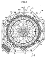
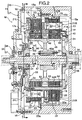
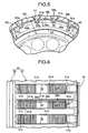
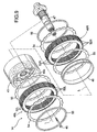
- Moteur comprenant :des stators annulaires (12L, 12R) agencés de façon à entourer un axe (L) ; un premier rotor (14) pouvant être mis en rotation autour de l'axe (L) ; et un second rotor (13) agencé entre le stator (12) et le premier moteur (14), et pouvant être mis en rotation autour de l'axe (L),dans lequel les stators (12L, 12R) comprennent une première rangée d'induits et une seconde rangée d'induits agencées dans la direction de l'axe (L), la première rangée d'induits comportant une pluralité de premiers induits (21L) agencés dans une direction circonférentielle et générant un premier champ magnétique rotatif tournant dans la direction circonférentielle par un pôle magnétique généré au niveau de la pluralité de premiers induits (21L) lors de l'alimentation en énergie électrique, la seconde rangée d'induits comprenant une pluralité de seconds induits (21R) agencés dans la direction circonférentielle et générant un second champ magnétique rotatif tournant dans la direction circonférentielle par rapport à un pôle magnétique généré au niveau de la pluralité des seconds induits (21R) lors de l'alimentation en énergie électrique ;dans lequel le premier rotor (14) comprend une première rangée d'aimants permanents et une seconde rangée magnétique permanente agencées dans la direction de l'axe (L), la première rangée d'aimants permanents comportant une pluralité de premiers aimants permanents (52L) agencés de façon à ce que leurs pôles magnétiques aient des polarités différentes en alternance avec un pas (P) prédéterminé dans la direction circonférentielle, la seconde rangée magnétique permanente comportant une pluralité de seconds aimants permanents (52R) agencés de façon à ce que leurs pôles magnétiques aient des polarités différentes en alternance avec le pas (P) prédéterminé dans la direction circonférentielle ;dans lequel le second rotor (13) comprend une première rangée de pôles magnétiques d'induction et une seconde rangée de pôles magnétiques d'induction agencées dans la direction de l'axe (L), la première rangée de pôles magnétiques d'induction comportant une pluralité de premiers pôles magnétiques d'induction (38L) agencée avec le pas (P) prédéterminé dans la direction circonférentielle et étant constituée d'un corps faiblement ferromagnétique ; et la seconde rangée de pôles magnétiques d'induction comportant une pluralité de seconds pôles magnétiques d'induction (38R) agencée avec le pas (P) prédéterminé dans la direction circonférentielle et constituée d'un corps faiblement ferromagnétique ; etdans lequel la première rangée d'induits et la première rangée d'aimants permanents sont opposées l'une à l'autre sur des côtés opposés dans la direction radiale de la première rangée de pôles magnétiques d'induction, respectivement, et la seconde rangée d'induits et la seconde rangée d'aimants permanents sont opposées l'une à l'autre sur des côtés opposés dans la direction radiale de la seconde rangée de pôles magnétiques d'induction, respectivement ;dans lequelune phase d'un pôle magnétique de la première rangée d'aimants permanents et une phase du pôle magnétique de la seconde rangée d'aimants permanents du premier rotor (14) sont éloignées l'une de l'autre par une moitié du pas (P) prédéterminé dans la direction circonférentielle, une phase de la polarité du premier champ magnétique rotatif et une phase de la polarité du second champ magnétique rotatif du stator (12) sont éloignées l'une de l'autre par une moitié du pas (P) prédéterminé dans la direction circonférentielle, et une phase du premier pôle magnétique d'induction (38L) et une phase du second pôle magnétique d'induction (38R) du second rotor (13) correspondent l'une à l'autre.
- Moteur selon la revendication 1, dans lequel une pluralité de fentes (31a) s'étendant de façon linéaire dans la direction de l'axe (L) est formée dans un corps de rotor cylindrique (31) du second rotor (13), et les premiers et seconds pôles magnétiques d'induction (38L, 38R) sont ajustés dans les fentes (31a).
- Moteur selon la revendication 1 ou 2, dans lequel le second rotor (13) est constitué d'un corps antimagnétique, et la pluralité de pôles magnétiques d'induction (38L, 38R) est supportée sur le second rotor (13) à des intervalles prédéterminés dans une direction circonférentielle, dans lequel les pôles magnétiques d'induction (38L, 38R) sont incorporés dans le second rotor (13).
- Moteur selon la revendication 3, dans lequel une partie de chaque pôle magnétique d'induction (38L, 38R) est exposée sur une surface circonférentielle externe du second rotor (13).
- Moteur selon la revendication 3 ou 4, dans lequel le second rotor (13) est en forme cylindrique, et une partie de chaque pôle magnétique d'induction (38L, 38R) est exposée sur une surface circonférentielle interne du second rotor (13).
- Moteur selon l'une quelconque des revendications 3 à 5, dans lequel une face sur laquelle le second rotor (13) est amené en contact avec les pôles magnétiques d'induction (38L, 38R) est dans une forme qui limite le mouvement des pôles magnétiques d'induction (38L, 38R) dans la direction radiale par rapport au second rotor (13).
- Moteur selon la revendication 6, dans lequel le mouvement des pôles magnétiques d'induction (38L, 38R) dans la direction radiale par rapport au second rotor (13) est limité par une mise en prise entre des protubérances disposées sur le second rotor (13) et des évidements (38a) disposés dans chaque pôle magnétique d'induction (38L, 38R).
- Moteur selon l'une quelconque des revendications 3 à 7, dans lequel le second rotor (13) comprend une pluralité de fentes (31a) s'étendant dans la direction de l'axe (L) ; et la pluralité de pôles magnétiques d'induction (38L, 38R) et d'entretoises (39) constituées d'un corps antimagnétique situés entre les pôles magnétiques d'induction (38L, 38R) adjacents dans la direction de l'axe (L) sont incorporés dans les fentes (31a).
- Moteur selon la revendication 8, dans lequel une face sur laquelle le second rotor (13) est amené en contact avec l'entretoise (39) est dans une forme qui limite le mouvement de l'entretoise (39) dans la direction radiale par rapport au second rotor (13).
- Moteur selon la revendication 8 ou 9, dans lequel une face circonférentielle externe de l'entretoise (39) est recouverte par un anneau (59) constitué d'un corps antimagnétique.
- Moteur selon l'une quelconque des revendications 3 à 10, comprenant en outre un support (41) permettant de limiter le mouvement des pôles magnétiques d'induction (38L, 38R) dans la direction de l'axe (L) par rapport au second rotor (13).
- Moteur selon l'une quelconque des revendications 3 à 11, dans lequel le second rotor (13) comprend en outre un corps de rotor (31) en forme de fond cylindrique ; un capot de rotor (33) relié au corps de rotor (31) de façon à recouvrir une ouverture du corps de rotor (31) ; et des arbres de rotation (34, 36) sont disposés dans des portions inférieures du corps de rotor (31) et du capot de rotor (33).
- Moteur selon l'une quelconque des revendications 1 à 12, dans lequel un angle (θ2) formé par des extrémités opposées dans la direction circonférentielle des pôles magnétiques d'induction (38L, 38R) des rangées de pôles magnétiques d'induction par rapport à l'axe (L) est établi de façon à être plus petit qu'au moins l'un parmi un angle d'un angle de machine (θ1) correspondant à un angle électrique de 180° des induits (21L, 21R) et un angle de machine (θ0) correspondant à l'angle électrique de 180° des pôles magnétiques (52L, 52R) des rangées magnétiques permanentes.
Applications Claiming Priority (5)
| Application Number | Priority Date | Filing Date | Title |
|---|---|---|---|
| JP2007026423A JP2008193823A (ja) | 2007-02-06 | 2007-02-06 | ロータ構造 |
| JP2007026422 | 2007-02-06 | ||
| JP2007026424 | 2007-02-06 | ||
| JP2007316189A JP4648378B2 (ja) | 2007-02-06 | 2007-12-06 | 電動機 |
| PCT/JP2008/050865 WO2008096600A1 (fr) | 2007-02-06 | 2008-01-23 | Moteur électrique, structure de rotor et machine magnétique |
Publications (3)
| Publication Number | Publication Date |
|---|---|
| EP2110933A1 EP2110933A1 (fr) | 2009-10-21 |
| EP2110933A4 EP2110933A4 (fr) | 2010-03-24 |
| EP2110933B1 true EP2110933B1 (fr) | 2012-08-01 |
Family
ID=40943393
Family Applications (1)
| Application Number | Title | Priority Date | Filing Date |
|---|---|---|---|
| EP08703706A Not-in-force EP2110933B1 (fr) | 2007-02-06 | 2008-01-23 | Moteur, structure de rotor et machine magnétique |
Country Status (8)
| Country | Link |
|---|---|
| US (1) | US20080238232A1 (fr) |
| EP (1) | EP2110933B1 (fr) |
| KR (1) | KR101121271B1 (fr) |
| AU (1) | AU2008212433B2 (fr) |
| BR (1) | BRPI0807008A2 (fr) |
| CA (1) | CA2677411A1 (fr) |
| MX (1) | MX2009008346A (fr) |
| WO (1) | WO2008096600A1 (fr) |
Families Citing this family (21)
| Publication number | Priority date | Publication date | Assignee | Title |
|---|---|---|---|---|
| CN101897108B (zh) * | 2007-12-26 | 2013-04-10 | 本田技研工业株式会社 | 电动机以及旋转电机用转子 |
| GB0810097D0 (en) * | 2008-06-03 | 2008-07-09 | Magnomatics Ltd | Magnetic gear |
| GB0808524D0 (en) * | 2008-05-12 | 2008-06-18 | Magnomatics Ltd | Magnetic pole-piece structure |
| IT1392883B1 (it) | 2008-09-03 | 2012-04-02 | Lenzi | Metodo per l'assemblaggio del rotore di una macchina elettrica rotante |
| EP2479871B1 (fr) * | 2011-01-19 | 2016-06-15 | GE Energy Power Conversion Technology Limited | Machines électriques |
| JP5350438B2 (ja) * | 2011-06-29 | 2013-11-27 | 株式会社日立製作所 | 磁気式歯車機構 |
| JP5772322B2 (ja) * | 2011-07-13 | 2015-09-02 | 株式会社豊田中央研究所 | 変速機構付き回転電機 |
| RU2475926C1 (ru) * | 2011-07-29 | 2013-02-20 | Открытое акционерное общество "Научно-производственная корпорация "Космические системы мониторинга, информационно-управляющие и электромеханические комплексы имени А.Г. Иосифьяна" (ОАО "Корпорация "ВНИИЭМ") | Роторная система магнитоэлектрической машины |
| ES2439550T3 (es) * | 2011-08-01 | 2014-01-23 | Siemens Aktiengesellschaft | Aparato de carga de imán |
| JP5808852B2 (ja) * | 2012-03-30 | 2015-11-10 | 本田技研工業株式会社 | 回転電機 |
| CN102842974B (zh) | 2012-08-03 | 2015-06-03 | 埃塞克科技有限公司 | 横向磁通发电机 |
| US9559559B2 (en) | 2012-09-24 | 2017-01-31 | Eocycle Technologies Inc. | Transverse flux electrical machine stator with stator skew and assembly thereof |
| CA2829812A1 (fr) | 2012-10-17 | 2014-04-17 | Eocycle Technologies Inc. | Rotor de machine electrique a flux transversal |
| JP6195989B2 (ja) * | 2014-06-17 | 2017-09-13 | 三菱電機株式会社 | 圧縮機、冷凍サイクル装置、および空気調和機 |
| GB2545154B (en) * | 2015-08-24 | 2021-12-01 | Magnomatics Ltd | Magnetically geared apparatus and a pole piece for such apparatus |
| CN106921234A (zh) * | 2017-05-16 | 2017-07-04 | 深圳市赫瑞科技有限公司 | 一种磁齿轮外转子安装结构 |
| UA124412C2 (uk) | 2017-12-22 | 2021-09-15 | Євгеній Віталійович Мушинський | Контрроторний синхронний електромеханічний перетворювач |
| US11522436B2 (en) | 2019-10-15 | 2022-12-06 | Darrell Schmidt Enterprises, Inc. | Permanently magnetized enhanced generator |
| WO2021076428A1 (fr) | 2019-10-15 | 2021-04-22 | Darrell Schmidt Enterprises, Inc. | Coupleur magnetique |
| JP7378592B2 (ja) * | 2020-04-16 | 2023-11-13 | 三菱電機株式会社 | 回転電機 |
| US11689088B2 (en) | 2020-08-12 | 2023-06-27 | Robert Willoughby Garrett, IV | Movable permanent magnet stator electric motor |
Citations (1)
| Publication number | Priority date | Publication date | Assignee | Title |
|---|---|---|---|---|
| EP2015428A1 (fr) * | 2006-08-09 | 2009-01-14 | HONDA MOTOR CO., Ltd. | Moteur |
Family Cites Families (27)
| Publication number | Priority date | Publication date | Assignee | Title |
|---|---|---|---|---|
| JPH04331445A (ja) * | 1991-05-01 | 1992-11-19 | Honda Motor Co Ltd | 誘導モータ |
| JPH0746807A (ja) * | 1993-05-21 | 1995-02-14 | Toshiba Corp | 回転電機の回転子 |
| JP3427511B2 (ja) | 1994-10-11 | 2003-07-22 | 株式会社デンソー | 二軸出力型電動機 |
| JP3190558B2 (ja) * | 1995-12-25 | 2001-07-23 | 三菱電機株式会社 | かご形誘導機の回転子の製造方法 |
| JP3051340B2 (ja) * | 1996-06-18 | 2000-06-12 | オークマ株式会社 | 同期電動機 |
| KR19990065127A (ko) * | 1998-01-08 | 1999-08-05 | 구자홍 | 매립 영구자석 동기전동기의 회전자 |
| JPH11341757A (ja) | 1998-05-21 | 1999-12-10 | Toyota Motor Corp | 電動機および動力伝達装置並びにハイブリッド車両 |
| US6274960B1 (en) * | 1998-09-29 | 2001-08-14 | Kabushiki Kaisha Toshiba | Reluctance type rotating machine with permanent magnets |
| US6590312B1 (en) * | 1999-11-18 | 2003-07-08 | Denso Corporation | Rotary electric machine having a permanent magnet stator and permanent magnet rotor |
| JP4269544B2 (ja) * | 2000-09-14 | 2009-05-27 | 株式会社デンソー | 複数ロータ型同期機 |
| JP2002122203A (ja) * | 2000-10-17 | 2002-04-26 | Minebea Co Ltd | リニアアクチュエータ |
| JP2002136094A (ja) * | 2000-10-30 | 2002-05-10 | Minebea Co Ltd | ステッピングモータ |
| US6774521B2 (en) * | 2001-05-16 | 2004-08-10 | Koyo Seiko Co., Ltd. | Brushless DC motor |
| US7064466B2 (en) * | 2001-11-27 | 2006-06-20 | Denso Corporation | Brushless rotary electric machine having tandem rotary cores |
| JP3724416B2 (ja) * | 2001-11-27 | 2005-12-07 | 株式会社デンソー | 軸方向分割混成磁極型ブラシレス回転電機 |
| GB0208565D0 (en) * | 2002-04-13 | 2002-05-22 | Rolls Royce Plc | A compact electrical machine |
| AU2003245151B2 (en) * | 2002-07-10 | 2008-11-13 | Danfoss A/S | Device to relieve thrust load in a rotor-bearing system using permanent magnets |
| JP4318959B2 (ja) * | 2003-05-21 | 2009-08-26 | 本田技研工業株式会社 | 永久磁石式回転子およびブラシレスモータ |
| US6924574B2 (en) * | 2003-05-30 | 2005-08-02 | Wisconsin Alumni Research Foundation | Dual-rotor, radial-flux, toroidally-wound, permanent-magnet machine |
| DE10354604B4 (de) * | 2003-11-21 | 2016-10-13 | Gesellschaft für Aufladetechnik und Spindelbau mbH | Stufenlos schaltbares, magnetodynamisches Getriebe |
| JP4069859B2 (ja) * | 2003-12-15 | 2008-04-02 | 日産自動車株式会社 | 回転電機の構造 |
| US7400077B2 (en) * | 2004-03-23 | 2008-07-15 | Electric Motor Development, Inc. | Electric motor having multiple armatures |
| JP4274473B2 (ja) * | 2004-06-14 | 2009-06-10 | ミネベア株式会社 | アクチュエータ |
| US7692357B2 (en) * | 2004-12-16 | 2010-04-06 | General Electric Company | Electrical machines and assemblies including a yokeless stator with modular lamination stacks |
| JP4508895B2 (ja) | 2005-02-02 | 2010-07-21 | 株式会社オーディオテクニカ | ハンギングマイクロホン |
| KR100652596B1 (ko) * | 2005-04-11 | 2006-12-01 | 엘지전자 주식회사 | 이중자석 하이브리드 유도 전동기 |
| JP4260799B2 (ja) * | 2005-12-02 | 2009-04-30 | 本田技研工業株式会社 | 電動機および電動機の駆動方法 |
-
2008
- 2008-01-23 KR KR1020097017237A patent/KR101121271B1/ko not_active IP Right Cessation
- 2008-01-23 AU AU2008212433A patent/AU2008212433B2/en not_active Ceased
- 2008-01-23 BR BRPI0807008-3A patent/BRPI0807008A2/pt not_active IP Right Cessation
- 2008-01-23 EP EP08703706A patent/EP2110933B1/fr not_active Not-in-force
- 2008-01-23 WO PCT/JP2008/050865 patent/WO2008096600A1/fr active Application Filing
- 2008-01-23 MX MX2009008346A patent/MX2009008346A/es active IP Right Grant
- 2008-01-23 CA CA002677411A patent/CA2677411A1/fr not_active Abandoned
- 2008-02-06 US US12/068,444 patent/US20080238232A1/en not_active Abandoned
Patent Citations (1)
| Publication number | Priority date | Publication date | Assignee | Title |
|---|---|---|---|---|
| EP2015428A1 (fr) * | 2006-08-09 | 2009-01-14 | HONDA MOTOR CO., Ltd. | Moteur |
Also Published As
| Publication number | Publication date |
|---|---|
| AU2008212433B2 (en) | 2011-08-11 |
| EP2110933A4 (fr) | 2010-03-24 |
| WO2008096600A1 (fr) | 2008-08-14 |
| KR20090104869A (ko) | 2009-10-06 |
| BRPI0807008A2 (pt) | 2014-04-22 |
| KR101121271B1 (ko) | 2012-03-26 |
| EP2110933A1 (fr) | 2009-10-21 |
| MX2009008346A (es) | 2009-08-20 |
| US20080238232A1 (en) | 2008-10-02 |
| AU2008212433A1 (en) | 2008-08-14 |
| CA2677411A1 (fr) | 2008-08-14 |
Similar Documents
| Publication | Publication Date | Title |
|---|---|---|
| EP2110933B1 (fr) | Moteur, structure de rotor et machine magnétique | |
| EP2226924B1 (fr) | Moteur et rotor de machine dynamo-électrique | |
| EP0558746B1 (fr) | Rotor de moteur sans balais | |
| CN101779366B (zh) | 轴向间隙型电动机 | |
| EP1990895B1 (fr) | Géométrie de rotor à aimants permanents à répartition de contraintes pour machines électriques | |
| WO2015146210A1 (fr) | Machine électrique rotative à aimants permanents et son procédé de fabrication | |
| EP2141784B1 (fr) | Rotor pour une machine rotative | |
| JP2009509490A (ja) | 電気機械の永久磁石励磁一次側磁極部材のための歯モジュール | |
| CN116057820A (zh) | 旋转电机以及定子的制造方法 | |
| JP3610961B2 (ja) | 回転電機及びその回転電機を用いたハイブリッド車両 | |
| CN101589537A (zh) | 电动机、转子构造及磁设备 | |
| JP5691451B2 (ja) | 回転電機用ロータ | |
| RU2435282C2 (ru) | Двигатель, структура ротора и магнитная машина | |
| EP4096062A1 (fr) | Stator et machine électrique rotative utilisant celui-ci | |
| JP4801824B2 (ja) | 磁気機械 | |
| JP2008193823A (ja) | ロータ構造 | |
| JP4680980B2 (ja) | 電動機 | |
| JP4482900B2 (ja) | アキシャルギャップ型モータ | |
| WO2023118983A1 (fr) | Réduction du couple de crantage dans des générateurs à aimants permanents à deux stators avec un flux radial de rotor intermédiaire | |
| JP4648378B2 (ja) | 電動機 | |
| JP4767997B2 (ja) | 回転電機用ロータおよび電動機 | |
| JP2008289227A (ja) | 回転電機用ロータ | |
| JP4691087B2 (ja) | 電動機 | |
| CN117220428A (zh) | 具有带轴向磁通磁体板的径向辐条式转子的转矩常数可变的电机及其方法 | |
| JPH0426350A (ja) | ブラシレスモータ |
Legal Events
| Date | Code | Title | Description |
|---|---|---|---|
| PUAI | Public reference made under article 153(3) epc to a published international application that has entered the european phase |
Free format text: ORIGINAL CODE: 0009012 |
|
| 17P | Request for examination filed |
Effective date: 20090806 |
|
| AK | Designated contracting states |
Kind code of ref document: A1 Designated state(s): AT BE BG CH CY CZ DE DK EE ES FI FR GB GR HR HU IE IS IT LI LT LU LV MC MT NL NO PL PT RO SE SI SK TR |
|
| A4 | Supplementary search report drawn up and despatched |
Effective date: 20100218 |
|
| 17Q | First examination report despatched |
Effective date: 20100303 |
|
| DAX | Request for extension of the european patent (deleted) | ||
| RTI1 | Title (correction) |
Free format text: MOTOR, ROTOR STRUCTURE AND MAGNETIC MACHINE |
|
| GRAP | Despatch of communication of intention to grant a patent |
Free format text: ORIGINAL CODE: EPIDOSNIGR1 |
|
| GRAS | Grant fee paid |
Free format text: ORIGINAL CODE: EPIDOSNIGR3 |
|
| GRAA | (expected) grant |
Free format text: ORIGINAL CODE: 0009210 |
|
| AK | Designated contracting states |
Kind code of ref document: B1 Designated state(s): AT BE BG CH CY CZ DE DK EE ES FI FR GB GR HR HU IE IS IT LI LT LU LV MC MT NL NO PL PT RO SE SI SK TR |
|
| REG | Reference to a national code |
Ref country code: GB Ref legal event code: FG4D |
|
| REG | Reference to a national code |
Ref country code: CH Ref legal event code: EP Ref country code: AT Ref legal event code: REF Ref document number: 569100 Country of ref document: AT Kind code of ref document: T Effective date: 20120815 |
|
| REG | Reference to a national code |
Ref country code: IE Ref legal event code: FG4D |
|
| REG | Reference to a national code |
Ref country code: DE Ref legal event code: R096 Ref document number: 602008017566 Country of ref document: DE Effective date: 20120927 |
|
| REG | Reference to a national code |
Ref country code: NL Ref legal event code: VDEP Effective date: 20120801 |
|
| REG | Reference to a national code |
Ref country code: AT Ref legal event code: MK05 Ref document number: 569100 Country of ref document: AT Kind code of ref document: T Effective date: 20120801 |
|
| REG | Reference to a national code |
Ref country code: LT Ref legal event code: MG4D Effective date: 20120801 |
|
| PG25 | Lapsed in a contracting state [announced via postgrant information from national office to epo] |
Ref country code: FI Free format text: LAPSE BECAUSE OF FAILURE TO SUBMIT A TRANSLATION OF THE DESCRIPTION OR TO PAY THE FEE WITHIN THE PRESCRIBED TIME-LIMIT Effective date: 20120801 Ref country code: IS Free format text: LAPSE BECAUSE OF FAILURE TO SUBMIT A TRANSLATION OF THE DESCRIPTION OR TO PAY THE FEE WITHIN THE PRESCRIBED TIME-LIMIT Effective date: 20121201 Ref country code: NO Free format text: LAPSE BECAUSE OF FAILURE TO SUBMIT A TRANSLATION OF THE DESCRIPTION OR TO PAY THE FEE WITHIN THE PRESCRIBED TIME-LIMIT Effective date: 20121101 Ref country code: LT Free format text: LAPSE BECAUSE OF FAILURE TO SUBMIT A TRANSLATION OF THE DESCRIPTION OR TO PAY THE FEE WITHIN THE PRESCRIBED TIME-LIMIT Effective date: 20120801 Ref country code: HR Free format text: LAPSE BECAUSE OF FAILURE TO SUBMIT A TRANSLATION OF THE DESCRIPTION OR TO PAY THE FEE WITHIN THE PRESCRIBED TIME-LIMIT Effective date: 20120801 Ref country code: AT Free format text: LAPSE BECAUSE OF FAILURE TO SUBMIT A TRANSLATION OF THE DESCRIPTION OR TO PAY THE FEE WITHIN THE PRESCRIBED TIME-LIMIT Effective date: 20120801 Ref country code: CY Free format text: LAPSE BECAUSE OF FAILURE TO SUBMIT A TRANSLATION OF THE DESCRIPTION OR TO PAY THE FEE WITHIN THE PRESCRIBED TIME-LIMIT Effective date: 20120801 |
|
| PG25 | Lapsed in a contracting state [announced via postgrant information from national office to epo] |
Ref country code: PL Free format text: LAPSE BECAUSE OF FAILURE TO SUBMIT A TRANSLATION OF THE DESCRIPTION OR TO PAY THE FEE WITHIN THE PRESCRIBED TIME-LIMIT Effective date: 20120801 Ref country code: SI Free format text: LAPSE BECAUSE OF FAILURE TO SUBMIT A TRANSLATION OF THE DESCRIPTION OR TO PAY THE FEE WITHIN THE PRESCRIBED TIME-LIMIT Effective date: 20120801 Ref country code: GR Free format text: LAPSE BECAUSE OF FAILURE TO SUBMIT A TRANSLATION OF THE DESCRIPTION OR TO PAY THE FEE WITHIN THE PRESCRIBED TIME-LIMIT Effective date: 20121102 Ref country code: PT Free format text: LAPSE BECAUSE OF FAILURE TO SUBMIT A TRANSLATION OF THE DESCRIPTION OR TO PAY THE FEE WITHIN THE PRESCRIBED TIME-LIMIT Effective date: 20121203 Ref country code: LV Free format text: LAPSE BECAUSE OF FAILURE TO SUBMIT A TRANSLATION OF THE DESCRIPTION OR TO PAY THE FEE WITHIN THE PRESCRIBED TIME-LIMIT Effective date: 20120801 Ref country code: BE Free format text: LAPSE BECAUSE OF FAILURE TO SUBMIT A TRANSLATION OF THE DESCRIPTION OR TO PAY THE FEE WITHIN THE PRESCRIBED TIME-LIMIT Effective date: 20120801 Ref country code: SE Free format text: LAPSE BECAUSE OF FAILURE TO SUBMIT A TRANSLATION OF THE DESCRIPTION OR TO PAY THE FEE WITHIN THE PRESCRIBED TIME-LIMIT Effective date: 20120801 |
|
| PG25 | Lapsed in a contracting state [announced via postgrant information from national office to epo] |
Ref country code: NL Free format text: LAPSE BECAUSE OF FAILURE TO SUBMIT A TRANSLATION OF THE DESCRIPTION OR TO PAY THE FEE WITHIN THE PRESCRIBED TIME-LIMIT Effective date: 20120801 |
|
| PG25 | Lapsed in a contracting state [announced via postgrant information from national office to epo] |
Ref country code: EE Free format text: LAPSE BECAUSE OF FAILURE TO SUBMIT A TRANSLATION OF THE DESCRIPTION OR TO PAY THE FEE WITHIN THE PRESCRIBED TIME-LIMIT Effective date: 20120801 Ref country code: RO Free format text: LAPSE BECAUSE OF FAILURE TO SUBMIT A TRANSLATION OF THE DESCRIPTION OR TO PAY THE FEE WITHIN THE PRESCRIBED TIME-LIMIT Effective date: 20120801 Ref country code: CZ Free format text: LAPSE BECAUSE OF FAILURE TO SUBMIT A TRANSLATION OF THE DESCRIPTION OR TO PAY THE FEE WITHIN THE PRESCRIBED TIME-LIMIT Effective date: 20120801 Ref country code: DK Free format text: LAPSE BECAUSE OF FAILURE TO SUBMIT A TRANSLATION OF THE DESCRIPTION OR TO PAY THE FEE WITHIN THE PRESCRIBED TIME-LIMIT Effective date: 20120801 Ref country code: ES Free format text: LAPSE BECAUSE OF FAILURE TO SUBMIT A TRANSLATION OF THE DESCRIPTION OR TO PAY THE FEE WITHIN THE PRESCRIBED TIME-LIMIT Effective date: 20121112 |
|
| PGFP | Annual fee paid to national office [announced via postgrant information from national office to epo] |
Ref country code: GB Payment date: 20130109 Year of fee payment: 6 Ref country code: FR Payment date: 20130225 Year of fee payment: 6 |
|
| PG25 | Lapsed in a contracting state [announced via postgrant information from national office to epo] |
Ref country code: IT Free format text: LAPSE BECAUSE OF FAILURE TO SUBMIT A TRANSLATION OF THE DESCRIPTION OR TO PAY THE FEE WITHIN THE PRESCRIBED TIME-LIMIT Effective date: 20120801 Ref country code: SK Free format text: LAPSE BECAUSE OF FAILURE TO SUBMIT A TRANSLATION OF THE DESCRIPTION OR TO PAY THE FEE WITHIN THE PRESCRIBED TIME-LIMIT Effective date: 20120801 |
|
| PLBE | No opposition filed within time limit |
Free format text: ORIGINAL CODE: 0009261 |
|
| STAA | Information on the status of an ep patent application or granted ep patent |
Free format text: STATUS: NO OPPOSITION FILED WITHIN TIME LIMIT |
|
| 26N | No opposition filed |
Effective date: 20130503 |
|
| PG25 | Lapsed in a contracting state [announced via postgrant information from national office to epo] |
Ref country code: BG Free format text: LAPSE BECAUSE OF FAILURE TO SUBMIT A TRANSLATION OF THE DESCRIPTION OR TO PAY THE FEE WITHIN THE PRESCRIBED TIME-LIMIT Effective date: 20121101 |
|
| PGFP | Annual fee paid to national office [announced via postgrant information from national office to epo] |
Ref country code: DE Payment date: 20130328 Year of fee payment: 6 |
|
| REG | Reference to a national code |
Ref country code: DE Ref legal event code: R097 Ref document number: 602008017566 Country of ref document: DE Effective date: 20130503 |
|
| PG25 | Lapsed in a contracting state [announced via postgrant information from national office to epo] |
Ref country code: MC Free format text: LAPSE BECAUSE OF NON-PAYMENT OF DUE FEES Effective date: 20130131 |
|
| REG | Reference to a national code |
Ref country code: CH Ref legal event code: PL |
|
| REG | Reference to a national code |
Ref country code: IE Ref legal event code: MM4A |
|
| PG25 | Lapsed in a contracting state [announced via postgrant information from national office to epo] |
Ref country code: LI Free format text: LAPSE BECAUSE OF NON-PAYMENT OF DUE FEES Effective date: 20130131 Ref country code: CH Free format text: LAPSE BECAUSE OF NON-PAYMENT OF DUE FEES Effective date: 20130131 |
|
| PG25 | Lapsed in a contracting state [announced via postgrant information from national office to epo] |
Ref country code: IE Free format text: LAPSE BECAUSE OF NON-PAYMENT OF DUE FEES Effective date: 20130123 |
|
| PG25 | Lapsed in a contracting state [announced via postgrant information from national office to epo] |
Ref country code: MT Free format text: LAPSE BECAUSE OF FAILURE TO SUBMIT A TRANSLATION OF THE DESCRIPTION OR TO PAY THE FEE WITHIN THE PRESCRIBED TIME-LIMIT Effective date: 20120801 |
|
| REG | Reference to a national code |
Ref country code: DE Ref legal event code: R119 Ref document number: 602008017566 Country of ref document: DE |
|
| GBPC | Gb: european patent ceased through non-payment of renewal fee |
Effective date: 20140123 |
|
| PG25 | Lapsed in a contracting state [announced via postgrant information from national office to epo] |
Ref country code: DE Free format text: LAPSE BECAUSE OF NON-PAYMENT OF DUE FEES Effective date: 20140801 |
|
| REG | Reference to a national code |
Ref country code: FR Ref legal event code: ST Effective date: 20140930 |
|
| REG | Reference to a national code |
Ref country code: DE Ref legal event code: R119 Ref document number: 602008017566 Country of ref document: DE Effective date: 20140801 |
|
| PG25 | Lapsed in a contracting state [announced via postgrant information from national office to epo] |
Ref country code: GB Free format text: LAPSE BECAUSE OF NON-PAYMENT OF DUE FEES Effective date: 20140123 Ref country code: FR Free format text: LAPSE BECAUSE OF NON-PAYMENT OF DUE FEES Effective date: 20140131 |
|
| PG25 | Lapsed in a contracting state [announced via postgrant information from national office to epo] |
Ref country code: TR Free format text: LAPSE BECAUSE OF FAILURE TO SUBMIT A TRANSLATION OF THE DESCRIPTION OR TO PAY THE FEE WITHIN THE PRESCRIBED TIME-LIMIT Effective date: 20120801 |
|
| PG25 | Lapsed in a contracting state [announced via postgrant information from national office to epo] |
Ref country code: LU Free format text: LAPSE BECAUSE OF NON-PAYMENT OF DUE FEES Effective date: 20130123 Ref country code: HU Free format text: LAPSE BECAUSE OF FAILURE TO SUBMIT A TRANSLATION OF THE DESCRIPTION OR TO PAY THE FEE WITHIN THE PRESCRIBED TIME-LIMIT; INVALID AB INITIO Effective date: 20080123 |