EP2110933B1 - Motor, rotor structure and magnetic machine - Google Patents
Motor, rotor structure and magnetic machine Download PDFInfo
- Publication number
- EP2110933B1 EP2110933B1 EP08703706A EP08703706A EP2110933B1 EP 2110933 B1 EP2110933 B1 EP 2110933B1 EP 08703706 A EP08703706 A EP 08703706A EP 08703706 A EP08703706 A EP 08703706A EP 2110933 B1 EP2110933 B1 EP 2110933B1
- Authority
- EP
- European Patent Office
- Prior art keywords
- rotor
- magnetic
- magnetic poles
- induction magnetic
- induction
- Prior art date
- Legal status (The legal status is an assumption and is not a legal conclusion. Google has not performed a legal analysis and makes no representation as to the accuracy of the status listed.)
- Not-in-force
Links
Images


Classifications
-
- H—ELECTRICITY
- H02—GENERATION; CONVERSION OR DISTRIBUTION OF ELECTRIC POWER
- H02K—DYNAMO-ELECTRIC MACHINES
- H02K16/00—Machines with more than one rotor or stator
- H02K16/02—Machines with one stator and two or more rotors
-
- H—ELECTRICITY
- H02—GENERATION; CONVERSION OR DISTRIBUTION OF ELECTRIC POWER
- H02K—DYNAMO-ELECTRIC MACHINES
- H02K1/00—Details of the magnetic circuit
- H02K1/06—Details of the magnetic circuit characterised by the shape, form or construction
- H02K1/22—Rotating parts of the magnetic circuit
- H02K1/24—Rotor cores with salient poles ; Variable reluctance rotors
- H02K1/246—Variable reluctance rotors
-
- H—ELECTRICITY
- H02—GENERATION; CONVERSION OR DISTRIBUTION OF ELECTRIC POWER
- H02K—DYNAMO-ELECTRIC MACHINES
- H02K1/00—Details of the magnetic circuit
- H02K1/06—Details of the magnetic circuit characterised by the shape, form or construction
- H02K1/22—Rotating parts of the magnetic circuit
- H02K1/27—Rotor cores with permanent magnets
- H02K1/2706—Inner rotors
- H02K1/272—Inner rotors the magnetisation axis of the magnets being perpendicular to the rotor axis
- H02K1/274—Inner rotors the magnetisation axis of the magnets being perpendicular to the rotor axis the rotor consisting of two or more circumferentially positioned magnets
- H02K1/2753—Inner rotors the magnetisation axis of the magnets being perpendicular to the rotor axis the rotor consisting of two or more circumferentially positioned magnets the rotor consisting of magnets or groups of magnets arranged with alternating polarity
- H02K1/276—Magnets embedded in the magnetic core, e.g. interior permanent magnets [IPM]
-
- H—ELECTRICITY
- H02—GENERATION; CONVERSION OR DISTRIBUTION OF ELECTRIC POWER
- H02K—DYNAMO-ELECTRIC MACHINES
- H02K1/00—Details of the magnetic circuit
- H02K1/06—Details of the magnetic circuit characterised by the shape, form or construction
- H02K1/22—Rotating parts of the magnetic circuit
- H02K1/28—Means for mounting or fastening rotating magnetic parts on to, or to, the rotor structures
- H02K1/30—Means for mounting or fastening rotating magnetic parts on to, or to, the rotor structures using intermediate parts, e.g. spiders
-
- H—ELECTRICITY
- H02—GENERATION; CONVERSION OR DISTRIBUTION OF ELECTRIC POWER
- H02K—DYNAMO-ELECTRIC MACHINES
- H02K16/00—Machines with more than one rotor or stator
-
- H—ELECTRICITY
- H02—GENERATION; CONVERSION OR DISTRIBUTION OF ELECTRIC POWER
- H02K—DYNAMO-ELECTRIC MACHINES
- H02K19/00—Synchronous motors or generators
- H02K19/02—Synchronous motors
- H02K19/10—Synchronous motors for multi-phase current
- H02K19/103—Motors having windings on the stator and a variable reluctance soft-iron rotor without windings
-
- H—ELECTRICITY
- H02—GENERATION; CONVERSION OR DISTRIBUTION OF ELECTRIC POWER
- H02K—DYNAMO-ELECTRIC MACHINES
- H02K21/00—Synchronous motors having permanent magnets; Synchronous generators having permanent magnets
- H02K21/12—Synchronous motors having permanent magnets; Synchronous generators having permanent magnets with stationary armatures and rotating magnets
- H02K21/14—Synchronous motors having permanent magnets; Synchronous generators having permanent magnets with stationary armatures and rotating magnets with magnets rotating within the armatures
- H02K21/16—Synchronous motors having permanent magnets; Synchronous generators having permanent magnets with stationary armatures and rotating magnets with magnets rotating within the armatures having annular armature cores with salient poles
Landscapes
- Engineering & Computer Science (AREA)
- Power Engineering (AREA)
- Permanent Magnet Type Synchronous Machine (AREA)
- Iron Core Of Rotating Electric Machines (AREA)
- Permanent Field Magnets Of Synchronous Machinery (AREA)
Abstract
Description
- The present invention relates to a motor comprising: annular stators arranged so as to surround an axis; a first rotor rotatable around the axis; and a second rotor arranged between the stator and the first rotor, and rotatable around the axis.
- A conventional motor disclosed in the following
Patent Publication 1, for example is known. This motor has an inner rotor, a stator, and an outer rotor. The inner rotor is in a columnar shape in which a plurality of permanent magnets slightly extending in the radial direction are arranged in the circumferential direction. The stator is in a cylindrical shape in which a plurality of armatures are arranged in the circumferential direction and fixed by a resin mold. The outer rotor is in a cylindrical shape including a coil wound around a core formed by a plurality of laminated rings, and electric power is not supplied to the coil. The inner rotor, the stator, and the outer rotor are disposed sequentially from the inside so as to be relatively rotatable. - In this motor, when power is supplied to the stator so as to generate a rotating magnetic field, a magnetic pole of the permanent magnet of the inner rotor is attracted/repelled with respect to the magnetic pole of the stator so that the inner rotor is rotated synchronously with the rotating magnetic field, and the outer rotor is rotated by electromagnetic induction without synchronization with the rotating magnetic field.
- Also, the following
Patent Publication 2 discloses a biaxial-output type motor in which an annular stator having a plurality of armatures and generating a rotating magnetic field is fixed to a casing, a first rotor supporting a plurality of permanent magnets on the outer circumference is rotatably supported within the stator, and a cylindrical second rotor supporting a plurality of induction magnetic poles made of a soft magnetic body is rotatably supported between the stator and the first rotor, whereby output can be individually taken out of the first rotor and the second rotor.
Patent Publication 1: Japanese Patent Application Laid-open No.11-341757
Patent Publication 2: Japanese Patent No.3427511 - However, the motor described in
Patent Publication 1 above has a problem that a high efficiency cannot be obtained since the outer rotor is rotated by electromagnetic induction, and the motor functions not as a synchronous machine but as an induction machine. Also, since the outer rotor is rotated by electromagnetic induction, an induction current generated at the coil of the outer rotor and an eddy current generated at the core of the outer rotor cause heat at the outer rotor, which results in a need to cool the outer rotor. - In order to solve the above problems, the applicant proposed a novel motor in Japanese Patent Application No.
2006-217141 EP 2015428 A1 is prior art according to Art. 54(3) EPC. - This motor comprises an annular stator arranged so as to surround an axis, an inner rotor rotatable around the axis, and an outer rotor arranged between the stator and the inner rotor and rotatable around the axis. The stator juxtapositionally comprises a first armature row including a plurality of first armatures and generating a first rotating magnetic field rotating along the circumferential direction, and a second armature row including a plurality of second armatures and generating a second rotating magnetic field rotating along the circumferential direction arranged. The inner rotor juxtapositionally comprises a first permanent magnet row including a plurality of first permanent magnets and a second permanent magnet row including a plurality of second permanent magnets. The outer rotor juxtapositionally comprises a first induction magnetic-pole row including a.plurality of first induction magnetic poles made of a soft magnetic body, and a second induction magnetic-pole row including a plurality of second induction magnetic poles made of a soft magnetic body arranged in the axial direction. The first armature row and the first permanent magnet row are opposed on opposite sides in the radial direction of the first induction magnetic-pole row, respectively, and the second armature row and the second permanent magnet row are opposed on opposite sides in the radial direction of the second induction magnetic-pole row, respectively.
- However, in the motor proposed in Japanese Patent Application No.
2006-217141 - Also, in the biaxial-output type motor disclosed in
Patent Publication 2 above, since fixing means such as a bolt is used as means to fix the induction magnetic pole to the rotor, the numbers of parts and assembling steps are increased accordingly, resulting in a problem of increased cost. Particularly, when the induction magnetic pole is made of laminated steel plates, not only it is difficult to accurately machine a female screw therein, but also bolt-fastening strength cannot be sufficiently secured. - Also, in the rotating motor as disclosed in Japanese Patent No.
3427511 - The present invention was made in view of the above circumstances, and has a first object to simplify the structure of a rotor supporting induction magnetic poles in a motor, and improve the strength.
- Also, the present invention has a second object to reliably fix the induction magnetic poles made of a soft magnetic body to the rotor with a simple structure.
- Moreover, the present invention has a third object to improve performance by minimizing short-circuit of a magnetic flux in a magnetic machine in which an induction magnetic-pole row is arranged between first and second magnetic-pole rows.
The patent applicationWO 2005/050824 discloses an electric motor with two rotors according to the introductory portion ofclaim 1. - The present invention refers to a motor as defined in the
independent claim 1. Further embodiments of the invention are claimed in thedependent claims 2 to 15. - With the feature of the present invention according to
claim 1, the motor comprises: an annular stator generating first and second rotating magnetic fields by first and second armatures arranged so as to surround an axis; a first rotor having first and second permanent magnet rows including first and second permanent magnets and rotatable around the axis; and a second rotor arranged between the stator and the first rotor, having first and second induction magnetic-pole rows including first and second induction magnetic poles, and rotatable around the axis. The first armature row and the first permanent magnet row are opposed on opposite sides in the radial direction of the first induction magnetic-pole row, respectively, and the second armature row and the second permanent magnet row are opposed on opposite sides in the radial direction of the second induction magnetic-pole row, respectively. Therefore, by controlling electricity to the first and second armatures so as to rotate the first and second rotating magnetic fields, a magnetic path is formed so as to pass through the first and second armatures, the first and second permanent magnets, and the first and second induction magnetic poles, so that one of or both the first rotor and the second rotor can be rotated. - At this time, the phase of the magnetic pole of the first permanent magnet row and the phase of the magnetic pole of the second permanent magnet row of the first rotor are displaced from each other by a half of a predetermined pitch in the circumferential direction, and the phase of polarity of the first rotating magnetic field and the phase of the polarity of the second rotating magnetic field of the stator are displaced from each other by a half of the predetermined pitch in the circumferential direction. Therefore, the phase of the first induction magnetic pole and the phase of the second induction magnetic pole of the second rotor can be matched with each other. By this arrangement, not only the structure of the second rotor is simplified and strength is improved, but also supporting and assembling of the first, second induction magnetic poles in the second rotor are facilitated.
- With the feature of the present invention according to
claim 2, since the first, second induction magnetic poles are fitted in the plurality of slits provided in the rotor body of the second rotor so as to extend in the axial direction, assembling of the first, second induction magnetic poles to the rotor body is facilitated. - With the feature according to
claim 3, the induction magnetic poles are embedded in the second rotor in order to support the plurality of induction magnetic poles made by a soft magnetic body with the predetermined intervals in the circumferential direction in the rotor made by a weak magnetic body and rotating around the axis. Therefore, it is possible to support the induction magnetic poles at the rotor without using a dedicated fixing member such as a bolt, thereby reducing the number of parts corresponding to the number of the fixing members. - With the feature according to claim 4, since a part of the induction magnetic pole is exposed on the outer-circumferential surface of the rotor, it is possible to reduce an air gap generated between the rotor and the magnetic pole and located outside the rotor.
- With the fifth feature, since the rotor has a cylindrical shape and a part of the induction magnetic pole is exposed on the inner-circumferential surface of the rotor, it is possible to reduce an air gap generated between the rotor and the magnetic pole and located inside the rotor.
- With the feature according to claim 6, since a face on which the rotor and the induction magnetic pole are in contact is made into a shape which limits movement of the induction magnetic pole in the radial direction with respect to the rotor, it is possible to prevent detachment of the induction magnetic pole due to a centrifugal force when the rotor is rotated.
- With the feature according to
claim 7, since the projections provided on the rotor and the recess provided in the induction magnetic poles are engaged with each other, not only movement of the induction magnetic poles in the radial direction with respect to the rotor is limited by the engagement, but also an unnecessary part of the induction magnetic pole is eliminated by the recess so that eddy loss and hysteresis loss can be reduced. - With the feature according to claim 8, since the plurality of induction magnetic poles and the spacers made by a weak magnetic body located between the induction magnetic poles adjacent in the axial direction are embedded in the plurality of slits provided in the rotor so as to extend in the axial direction, not only assembling of the induction magnetic poles and spacers to the rotor is facilitated but also a magnetic path is cut by the spacers of the weak magnetic body between the induction magnetic poles adjacent in the axial direction.
- With the feature according to claim 9, since the face on which the rotor and the spacer are in contact is made into a shape which limits movement of the spacer in the radial direction with respect to the rotor, it is possible to prevent detachment of the spacer due to a centrifugal force when the rotor is rotated.
- With the feature according to
claim 10, since the outer-circumferential face of the spacer is covered by the ring made by a weak magnetic body, not only it is possible to more reliably prevent detachment of the spacer due to a centrifugal force when the rotor is rotated, but also it is possible to prevent bulging of the central part of the rotor in the axial direction due to the centrifugal force. Supposing that a ring is wound around the soft magnetic body, an unnecessary gap is generated on the outer-circumferential face of the soft magnetic body, but the generation of the gap can be prevented by winding the ring on the outer-circumferential face of the spacer. - With the feature according to
claim 11, since the holder is provided in order to limit movement of the induction magnetic pole in the axial direction with respect to the rotor, it is possible to prevent detachment of the induction magnetic pole from the rotor in the axial direction. - With the feature according to claim 12, since the rotor comprises the rotor body in a bottomed cylindrical shape and the cover connected to the rotor body so as to cover the opening of the rotor body, and the rotating shafts are provided in the bottom portions of the rotor body and the cover, the rotor is supported at its opposite ends to stabilize the rotation.
- With the feature according to
claim 13, in the motor in which the induction magnetic-pole row is arranged between the armature rows and the permanent magnetic rows, the angle formed between opposite ends in the circumferential direction of the induction magnetic poles of the induction magnetic-pole row with respect to the axis is made smaller than at least one of the machine angle corresponding to an electric angle of 180° of the magnetic pole of the first and second armature rows and the machine angle corresponding to an electric angle of 180° of the magnetic pole of the first and second permanent magnet row. Therefore, it is possible to suppress a magnetic short-circuit from being generated between the magnetic poles adjacent in the circumferential direction of the armature rows or the permanent magnet rows through the induction magnetic pole of the induction magnetic-pole row, thereby improving magnetic efficiency. - With the feature according to
claim 14, the first rotor or the induction magnetic-pole row is moved so as to function as a motor. - With the feature according to
claim 15, the first rotor or the induction magnetic-pole row is moved by an external force. Therefore, it is possible to generate an electromotive force at the plurality of armatures so that they function as a motor. -
- [
FIG. 1] FIG. 1 is a front view of a motor according to a first embodiment, taken in the axial direction (view taken along line 1-1 inFIG. 2 ). (first embodiment) - [
FIG. 2] FIG. 2 is a sectional view taken along line 2-2 inFIG. 1 . (first embodiment) - [
FIG. 3] FIG. 3 is a sectional view taken along line 3-3 inFIG. 2 . (first embodiment) - [
FIG. 4] FIG. 4 is a sectional view taken along line 4-4 inFIG. 2 . (first embodiment) - [
FIG. 5] FIG. 5 is a sectional view taken along line 5-5 inFIG. 2 . (first embodiment) - [
FIG. 6] FIG. 6 is a sectional view taken along line 6-6 inFIG. 3 . (first embodiment) - [
FIG. 7] FIG. 7 is an exploded perspective view of the motor. (first embodiment) - [
FIG. 8] FIG. 8 is an exploded perspective view of an outer rotor. (first embodiment) - [
FIG. 9] FIG. 9 is an exploded perspective view of an inner rotor. (first embodiment) - [
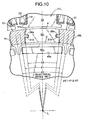
FIG. 10] FIG. 10 is an enlarged view ofpart 10 inFIG. 3 . (first embodiment) - [
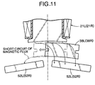
FIG. 11 FIG. 11 is a view for explaining magnetic short-circuit of a permanent magnet of the inner rotor. (first embodiment) - [
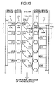
FIG. 12] FIG. 12 is a schematic diagram where the motor is expanded in the circumferential direction. (first embodiment) - [
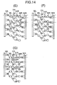
FIG. 13] FIG. 13 are first operational explanatory views when the inner rotor is fixed. (first embodiment) - [
FIG. 14] FIG. 14 are second operational explanatory views when the inner rotor is fixed. (first embodiment) - [
FIG. 15] FIG. 15 are third operational explanatory views when the inner rotor is fixed. (first embodiment) - [
FIG. 16] FIG. 16 are first operational explanatory views when the outer rotor is fixed. (first embodiment) - [
FIG. 17] FIG. 17 are second operational explanatory views when the outer rotor is fixed. (first embodiment) - [
FIG. 18] FIG. 18 are views illustrating shapes of a projection of a spacer according to a second embodiment. (second embodiment) - [
FIG. 19] FIG. 19 is a view corresponding toFIG. 6 according to a third embodiment. (third embodiment) - [
FIG. 20] FIG. 20 is a sectional view taken along line 20-20 inFIG. 19 . (third embodiment) - [
FIG. 21] FIG. 21 is a sectional view taken along line 21-21 inFIG. 19 . (third embodiment) - [
FIG. 22] FIG. 22 are views corresponding toFIG. 10 according to a fourth embodiment. (fourth embodiment) - [
FIG. 23] FIG. 23 is a view corresponding toFIG. 10 according to a fifth example. - [
FIG. 24] FIG. 24 is a view corresponding toFIG. 3 according to a sixth example. - [
FIG. 25] FIG. 25 are enlarged views of essential parts inFIG.24 . -
- 12L
- first stator (stator)
- 12R
- second stator (stator)
- 13
- outer rotor (rotor, second rotor)
- 14
- inner rotor (first rotor)
- 21L
- first armature (magnetic pole of first magnetic-pole row, armature)
- 21R
- second armature (magnetic pole of first magnetic-pole row, armature)
- 31
- rotor body
- 31a
- slit
- 31b
- projection
- 33
- rotor cover
- 34
- first outer rotor shaft (rotating shaft)
- 36
- second outer rotor shaft (rotating shaft)
- 38L
- first induction magnetic pole (induction magnetic pole)
- 38R
- second induction magnetic pole (induction magnetic pole)
- 38a
- recess
- 39
- spacer
- 41
- holder
- 52L
- first permanent magnet (magnetic pole of second magnetic-pole row)
- 52R
- second permanent magnet (magnetic pole of second magnetic-pole row)
- 59
- ring
- L
- axis
- L0
- distance
- L2
- distance
- θ0
- machine angle
- θ2
- angle
- P
- predetermined pitch
- Embodiments of the present invention will be described based on the attached drawings.
- A first embodiment of the present invention will be described based on
FIGS. 1 to 17 . - As shown in
FIG. 7 , a motor M of this embodiment comprises acasing 11 forming an octagonal cylindrical shape, which is short in a direction of an axis L, annular first andsecond stators casing 11, a cylindricalouter rotor 13 accommodated within the first andsecond stators inner rotor 14 accommodated within theouter rotor 13 and rotating around the axis L. Theouter rotor 13 and theinner rotor 14 are capable of relative rotation with respect to the fixed first andsecond stators - As obvious from
FIGS. 1 and2 , thecasing 11 has an octagonal bottomedcylindrical body portion 15 and an octagonal-plate-shapedlid portion 17 fixed to an opening of thebody portion 15 with a plurality ofbolts 16. A plurality ofopenings body portion 15 and thelid portion 17. - As obvious from
FIGS. 1 to 4 and7 , the first andsecond stators first stator 12L as a representative. Thefirst stator 12L has a plurality (24 pieces in the embodiment) offirst armatures 21L each including acoil 20 wound around the outer circumference of a core 18 made of laminated steel plates with aninsulator 19 therebetween. Thesefirst armatures 21L are integrated by a ring-shapedholder 22 while being connected in the circumferential direction so as to form generally annular shape. Aflange 22a projecting in the radial direction from one end on the axis L direction of theholder 22 is fixed to a steppedportion 15b (seeFIG. 2 ) on the inner face of thebody portion 15 in thecasing 11 by a plurality ofbolts 23. - The
second stator 12R is provided with 24 pieces ofsecond armatures 21R similarly to thefirst stator 12L. Theflange 22a of theholder 22 is fixed to a steppedportion 15c (seeFIG. 2 ) on the inner face of thebody portion 15 in thecasing 11 by a plurality ofbolts 24. At this time, phases in the circumferential direction of thefirst stator 12L and thesecond stator 12R are displaced from each other by a half of a pitch of first and secondpermanent magnets FIGS. 3 and4 ). A three-phase alternating current is supplied from threeterminals FIG. 1 ) provided at thebody portion 15 of thecasing 11 to the first andsecond armatures second stators second stators - As obvious from
FIGS. 2 ,7 and8 , theouter rotor 13 is a hollow member including arotor body 31 formed by a weak magnetic body in a bottomed cylindrical shape, and arotor cover 33 formed by a weak magnetic body into a disk shape and fixed bybolts 32 so as to cover the opening of therotor body 31. A firstouter rotor shaft 34 projecting from the center of the bottom portion of therotor body 31 onto the axis L is rotatably supported by thebody portion 15 of thecasing 11 by aball bearing 35. A secondouter rotor shaft 36 projecting from the center of therotor cover 33 onto the axis L is rotatably supported on thelid portion 17 of thecasing 11 by aball bearing 37. The firstouter rotor shaft 34 serving as an output shaft of theouter rotor 13 penetrates thebody portion 15 of thecasing 11 to extend outside. - The weak magnetic body is a material not attracted by a magnet, includes resin, wood and the like in addition to aluminum and the like, and is also called as a non-magnetic body in some cases.
- As obvious from
FIGS. 2 ,6 ,8 and10 , a plurality of (20 in the embodiment) slits 31a extending in parallel with the axis L are formed in the outer circumferential face of therotor body 31 so as to communicate with the inside and outside in the radial direction. Eachslit 31a is opened on the bottom-portion side of therotor body 31, and closed on the opening side of therotor body 31. First inductionmagnetic poles 38L made by a soft magnetic body, spacers 39, and second inductionmagnetic poles 38R made by a soft magnetic body are inserted into theslits 31a in the axis L direction from the bottom-portion side of therotor body 31 and embedded therein. The first and second inductionmagnetic poles - A pair of
projections slit 31a in therotor body 31. A pair ofrecesses projections magnetic poles spacer 39 brought into contact with the inner face of theslits 31a. - Among the first and second induction
magnetic poles spacer 39 inserted into theslit 31a as described above, the front end of the first inductionmagnetic pole 38L is brought into contact with astopper 31c (seeFIG. 6 ) at the front end of theslit 31a so as to limit their movement. In this state, one of a plurality ofelastic claws 41a projecting in the axis L direction from anannular holder 41 fixed to the bottom portion of therotor body 31 bybolts 40 is brought into resilient contact with the rear end of the second inductionmagnetic pole 38R. As a result, the first and second inductionmagnetic poles spacer 39 inserted into theslit 31a are retained by thestopper 31c and theelastic claw 41a of theholder 41, whereby they are prevented from being pulled out in the axis L direction and rattling is prevented from occurring. - As obvious from
FIG. 2 , afirst resolver 42 for detecting a rotating position of theouter rotor 13 is provided so as to surround the secondouter rotor shaft 36 of theouter rotor 13. Thefirst resolver 42 comprises aresolver rotor 43 fixed to the outer circumference of the secondouter rotor shaft 36, and aresolver stator 44 fixed to thelid portion 17 of thecasing 11 so as to surround the periphery of theresolver rotor 43. - As obvious from
FIGS. 2 to 5 and9 , theinner rotor 14 comprises arotor body 45 formed into a cylindrical shape, aninner rotor shaft 47 penetrating ahub 45a of therotor body 45 and fixed by abolt 46, annular first andsecond rotor cores rotor body 45, and anannular spacer 49 fitted on the outer circumference of therotor body 45. One end of theinner rotor shaft 47 is rotatably supported on the axis L by aball bearing 50 within the firstouter rotor shaft 34. The other end of theinner rotor shaft 47 is rotatably supported by aball bearing 51 within the secondouter rotor shaft 36, and penetrates the secondouter rotor shaft 36 and thelid portion 17 of thecasing 11 to extend outside thecasing 11 so as to serve as an output shaft of theinner rotor 14. - The first and
second rotor cores rotor body 45 have the same structure, and are provided with a plurality of (20 pieces in the embodiment) permanentmagnet supporting holes 48a along the outer-circumferential face (seeFIGS. 3 and4 ), into which the first and secondpermanent magnets permanent magnets 52L of thefirst rotor core 48L are alternately reversed, the polarity of the adjacent secondpermanent magnets 52R of thesecond rotor core 48R are alternately reversed, and the phase in the circumferential direction of the firstpermanent magnets 52L in thefirst rotor core 48L and the phase in the circumferential direction of the secondpermanent magnets 52R in thesecond rotor core 48R are displaced from each other by a half of the pitch (seeFIGS. 3 and4 ). - The
spacer 49 made of the weak magnetic body is fitted in a central portion in the axis L direction in the outer circumference of therotor body 45; a pair of inner permanent-magnet support plates permanent magnets second rotor cores magnet support plates permanent magnets - As obvious from
FIG. 2 , asecond resolver 56 for detecting a rotational position of theinner rotor 14 is provided so as to surround theinner rotor shaft 47. Thesecond resolver 56 comprises aresolver rotor 57 fixed to the outer circumference of theinner rotor shaft 47, and aresolver stator 58 fixed to thelid portion 17 of thecasing 11 so as to surround the periphery of theresolver rotor 57. - Therefore, as shown in
FIG. 10 in an enlarged manner, the inner circumferential face of thefirst armatures 21L of thefirst stator 12L is opposed through a slight air gap α
to the outer circumference face of the first inductionmagnetic poles 38L exposed on the outer circumferential face of theouter rotor 13, and the outer circumferential face of thefirst rotor core 48L of theinner rotor 14 is opposed through a slight air gap β to the inner circumferential face of the first inductionmagnetic poles 38L exposed on the inner circumferential face of
theouter rotor 13. Similarly, the inner circumferential face of thesecond armatures 21R of thesecond stator 12R is opposed through a slight air gap α to the outer circumference face of the second inductionmagnetic poles 38R exposed on the outer circumferential face of theouter rotor 13, and the outer circumferential face of thesecond rotor core 48R of theinner rotor 14 is opposed through a slight air gap β to the inner circumferential face of the second inductionmagnetic poles 38R exposed on the inner circumferential face of theouter rotor 13. - Next, an operational principle of the motor M of the first embodiment having the above-described structure will be described.
-
FIG. 12 schematically shows a state where the motor M is extended in the circumferential direction. On both right and left sides inFIG. 12 , the first and secondpermanent magnets inner rotor 14 are shown, respectively. The first and secondpermanent magnets FIG. 12 ) with N pole and S pole provided alternately at a predetermined pitch P. The firstpermanent magnets 52L and the secondpermanent magnets 52R are arranged while displaced from each other by only a half of the predetermined pitch P, that is, a half pitch P/2. - At the center of
FIG. 12 , virtualpermanent magnets 21 corresponding to the first andsecond armatures second stators second armatures second stators permanent magnets inner rotor 14 is 20, respectively. Thus, the pitch of the first and thesecond armatures permanent magnets inner rotor 14. - However, since the first and
second armatures second armatures permanent magnets 21 arranged with the pitch P and rotated in the circumferential direction. The first andsecond armatures magnetic poles permanent magnets 21. The polarity of the first and second virtualmagnetic poles permanent magnets 21 adjacent in the circumferential direction are alternately reversed, and the first virtualmagnetic poles 21L and the second virtualmagnetic poles 21R of the virtualpermanent magnets 21 are displaced from each other in the circumferential direction by the half pitch P/2. - The first and second induction
magnetic poles outer rotor 13 are arranged between the first and secondpermanent magnets permanent magnets 21. The first and second inductionmagnetic poles magnetic poles 38L and the second inductionmagnetic poles 38R in the axis L direction. - As shown in
FIG. 12 , when the polarity of the first virtualmagnetic pole 21L of the virtualpermanent magnet 21 is different from the polarity of the opposing (closest) firstpermanent magnet 52L, the polarity of the second virtualmagnetic pole 21R of the virtualpermanent magnet 21 becomes the same as that of the opposing (closest) secondpermanent magnet 52R. Also, when the polarity of the second virtualmagnetic pole 21R of the virtualpermanent magnet 21 is different from the polarity of the opposing (closest) secondpermanent magnet 52R, the polarity of the first virtualmagnetic pole 21L of the virtualpermanent magnet 21 becomes the same as that of the opposing (closest) firstpermanent magnet 52L (seeFIG. 14(G) ). - First, the operation will be described in a case where a rotating magnetic field is generated at the first and
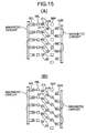
second stators magnetic poles magnetic poles permanent magnets permanent magnets 21 are rotated downward in the figures with respect to the fixed first and secondpermanent magnets FIG. 13 (A), FIG. 13 (B), FIG. 13(C), FIG. 13(D) ,FIG. 14(E), FIG. 14(F), and FIG. 14(G) , whereby the first and second inductionmagnetic poles - In
FIG. 13 (A) , the first inductionmagnetic poles 38L are aligned with respect to the opposing firstpermanent magnets 52L and the first virtualmagnetic poles 21L of the virtualpermanent magnets 21, and the second inductionmagnetic poles 38R are displaced by the half pitch P/2 with respect to the opposing second virtualmagnetic poles 21R and the secondpermanent magnets 52R. In this state, the virtualpermanent magnets 21 are rotated downward inFIG. 13(A) . At the beginning of the rotation, the polarity of the first virtualmagnetic poles 21L of the virtualpermanent magnets 21 is different from the polarity of the opposing firstpermanent magnets 52L, and the polarity of the second virtualmagnetic poles 21R of the virtualpermanent magnets 21 is the same as the polarity of the opposing secondpermanent magnets 52R. - Since the first induction
magnetic poles 38L are arranged between the firstpermanent magnets 52L and the first virtualmagnetic poles 21L of the virtualpermanent magnets 21, the first inductionmagnetic poles 38L are magnetized by the firstpermanent magnets 52L and the first virtualmagnetic poles 21L, whereby a first magnetic line G1 is generated between the firstpermanent magnets 52L, the first inductionmagnetic poles 38L and the first virtualmagnetic poles 21L. Similarly, since the second inductionmagnetic poles 38R are arranged between the second virtualmagnetic poles 21R and the secondpermanent magnets 52R, the second inductionmagnetic poles 38R are magnetized by the second virtualmagnetic poles 21R and the secondpermanent magnets 52R, whereby a second magnetic line G2 is generated between the second virtualmagnetic poles 21R, the second inductionmagnetic poles 38R and the secondpermanent magnets 52R. - In a state shown in
FIG. 13(A) , the first magnetic line G1 is generated so as to connect together the firstpermanent magnets 52L, the first inductionmagnetic poles 38L, and the first virtualmagnetic poles 21L, while the second magnetic line G2 is generated so as to connect each two second virtualmagnetic poles 21R adjacent in the circumferential direction and the second inductionmagnetic poles 38R located therebetween and to connect each two secondpermanent magnets 52R adjacent in the circumferential direction and the second inductionmagnetic poles 38R located therebetween. As a result, in this state, a magnetic circuit is established as shown inFIG. 15(A) . In this state, a magnetic force for rotation in the circumferential direction does not act on the first inductionmagnetic poles 38L, since the first magnetic line G1 is linear. Also, a bending degree and a total magnetic flux of the two second magnetic lines G2 are equal to each other between each two second virtualmagnetic poles 21R adjacent in the circumferential direction and the second inductionmagnetic poles 38R, and the bending degree and the total magnetic flux amount of the two second magnetic lines G2 are also equal to each other between each two secondpermanent magnets 52R adjacent in the circumferential direction and the second inductionmagnetic poles 38R, thereby establishing a balance. Thus, a magnetic force for rotation in the circumferential direction does not act on the second inductionmagnetic poles 38R, either. - When the virtual
permanent magnets 21 are rotated from positions shown inFIG. 13(A) to positions shown inFIG. 13(B) , the second magnetic line G2 connecting together the second virtualmagnetic poles 21R, the second inductionmagnetic poles 38R, and the secondpermanent magnets 52R is generated, and the first magnetic line G1 between the first inductionmagnetic poles 38L and the first virtualmagnetic poles 21L is bent. With this operation, the first and second magnetic lines G1 and G2 establish a magnetic circuit as shown inFIG. 15(B) . - In this state, although the bending degree of the first magnetic line G1 is small, the total magnetic flux amount is large, and thus a relatively large magnetic force acts on the first induction
magnetic poles 38L. By this arrangement, the first inductionmagnetic poles 38L are driven by a relatively large driving force in the rotating direction of the virtualpermanent magnets 21, that is, in the magnetic field rotating direction. As a result, theouter rotor 13 is rotated in the magnetic field rotating direction. Also, although the bending degree of the second magnetic line G2 is large, the total magnetic flux amount is small, and thus a relatively small magnetic force acts on the second inductionmagnetic poles 38R, whereby the second inductionmagnetic poles 38R are driven by a relatively small driving force in the magnetic field rotating direction. As a result, theouter rotor 13 is rotated in the magnetic field rotating direction. - Then, when the virtual
permanent magnets 21 are rotated from positions shown inFIG. 13(B) to positions shown inFIGS. 13(C), 13(D) ,14(E), and 14 (F) in this order, the first inductionmagnetic poles 38L and the second inductionmagnetic poles 38R are driven in the magnetic field rotating direction by a magnetic force caused by the first and second magnetic lines G1, G2, respectively. As a result, theouter rotor 13 is rotated in the magnetic field rotating direction. During this process, although the bending degree of the first magnetic line G1 becomes larger, the total magnetic flux amount becomes smaller, and thus the magnetic force acting on the first inductionmagnetic poles 38L is gradually weakened, whereby the driving force driving the first inductionmagnetic poles 38L in the magnetic field rotating direction is gradually reduced. Also, although the bending degree of the second magnetic line G2 becomes smaller, the total magnetic flux amount becomes larger, and thus the magnetic force acting on the second inductionmagnetic poles 38R becomes gradually stronger, whereby the driving force driving the second inductionmagnetic poles 38R in the magnetic field rotating direction is gradually increased. - While the virtual
permanent magnets 21 are rotated from positions shown inFIG. 14(E) to positions shown inFIG. 14(F) , the second magnetic line G2 is bent, and the total magnetic flux amount becomes close to the largest. As a result, the strongest magnetic force acts on the second inductionmagnetic poles 38R, and the driving force acting on the second inductionmagnetic poles 38R becomes the largest. Thereafter, as shown inFIG. 14(G) , the virtualpermanent magnet 21 is rotated by the pitch P from the initial position inFIG. 13(A) , and the first and second virtualmagnetic poles permanent magnet 21 are rotated to the position opposed to the first and secondpermanent magnets FIG. 13(A) . Only at this moment, the magnetic force does not act for rotating theouter rotor 13 in the circumferential direction. - In this state, when the virtual
permanent magnet 21 is further rotated, the first and second inductionmagnetic poles outer rotor 13 is rotated in the magnetic rotating direction. At this time, while the virtualpermanent magnet 21 is rotated and returned to the position shown inFIG. 13(A) again, the magnetic force acting on the first inductionmagnetic poles 38L becomes stronger conversely to the above case since the total magnetic flux amount is increased although the bending degree of the first magnetic line G1 is decreased, so that the driving force acting on the first inductionmagnetic poles 38L becomes larger. On the other hand, the magnetic force acting on the second inductionmagnetic poles 38R is weakened since the total magnetic flux amount is decreased although the bending degree of the second magnetic line G2 is increased, so that the driving force acting on the second inductionmagnetic poles 38R becomes smaller. - As obvious from comparison between
FIG. 13(A) andFIG. 14(G) , with rotation of the virtualpermanent magnet 21 by the pitch P, the first and second inductionmagnetic poles outer rotor 13 is rotated at a speed of 1/2 of the rotating speed of the rotating magnetic field of the first andsecond stators magnetic poles permanent magnets 52L and the first virtualmagnetic poles 21L connected by the first magnetic line G1 and between the secondpermanent magnets 52R and the second virtualmagnetic poles 21R connected by the second magnetic line G2. - Next, operation of the motor M when the
inner rotor 14 is rotated while theouter rotor 13 is fixed will be described with reference toFIGS. 15 and16 . - First, as shown in
FIG. 16(A) , in a state where each of the first inductionmagnetic poles 38L is opposed to each of the firstpermanent magnets 52L, and each of the second inductionmagnetic poles 38R is located between each two of the adjacent secondpermanent magnets 52R, the first and second rotating magnetic fields are rotated downward inFIG. 16(A) . At beginning of the rotation, the polarity of each of the first virtualmagnetic poles 21L is made different from the polarity of each of the opposing firstpermanent magnets 52L, and the polarity of each of the second virtualmagnetic poles 21R is made the same as the polarity of each of the opposing secondpermanent magnets 52R. - In this state, when the virtual
permanent magnets 21 are rotated to positions shown inFIG. 16(B) , the first magnetic line G1 between the first inductionmagnetic poles 38L and the first virtualmagnetic poles 21L is bent, and the second virtualmagnetic poles 21R approaches the second inductionmagnetic poles 38R. Therefore, the second magnetic line G2 connecting together the second virtualmagnetic poles 21R, the second inductionmagnetic poles 38R, and the secondpermanent magnets 52R is generated. As a result, a magnetic circuit as shown inFIG. 15 (B) described above is established at the first and secondpermanent magnets permanent magnets 21 and the first and second inductionmagnetic poles - In this state, although the total magnetic flux amount of the first magnetic line G1 between the first
permanent magnets 52L and the first inductionmagnetic poles 38L is large, the first magnetic line G1 is straight, and thus a magnetic force to rotate the firstpermanent magnets 52L with respect to the first inductionmagnetic poles 38L is not generated. Also, since a distance between the secondpermanent magnets 52R and the second virtualmagnetic poles 21R having a polarity different therefrom is relatively long, although the total magnetic flux amount of the second magnetic line G2 between the second inductionmagnetic poles 38R and the secondpermanent magnets 52R is relatively small, the bending degree is large, and thus a magnetic force to bring the secondpermanent magnets 52R close to the second inductionmagnetic poles 38R acts on the secondpermanent magnets 52R. Therefore, the secondpermanent magnets 52R are driven together with the firstpermanent magnets 52L in the rotating direction of the virtualpermanent magnets 21, that is, a direction (upper side inFIGS. 16 (A) to 16 (D) ) opposite from the magnetic field rotating direction, and rotated toward a position shown inFIG. 16(C) . With this rotation, theinner rotor 14 is rotated in a direction opposite from the magnetic field rotating direction. - While the first and second
permanent magnets FIG. 16 (B) toward the positions shown inFIG. 16(C) , the virtualpermanent magnets 21 are rotated toward a position shown inFIG. 16(D) . As described above, when the secondpermanent magnets 52R approaches the second inductionmagnetic poles 38R, the bending degree of the second magnetic line G2 between the second inductionmagnetic poles 38R and the secondpermanent magnets 52R becomes smaller, but the total magnetic flux amount of the second magnetic line G2 becomes larger as the virtualpermanent magnets 21 further approaches the second inductionmagnetic poles 38R. As a result, also in this case, the magnetic force to bring the secondpermanent magnets 52R closer to the second inductionmagnetic poles 38R acts on the secondpermanent magnets 52R, whereby the secondpermanent magnets 52R are driven together with the firstpermanent magnets 52L in a direction opposite from the magnetic field rotating direction. - Also, as the first
permanent magnets 52L is rotated in a direction opposite from the magnetic field rotating direction, the first magnetic line G1 between the firstpermanent magnets 52L and the first inductionmagnetic poles 38L is bent, and thus a magnetic force to bring the firstpermanent magnets 52L closer to the first inductionmagnetic poles 38L acts on the firstpermanent magnets 52L. However, in this state, the magnetic force caused by the first magnetic line G1 is weaker than the magnetic force caused by the second magnetic line G2, since the bending degree of the first magnetic line G1 is smaller than the second magnetic line G2. As a result, the secondpermanent magnets 52R are driven together with the firstpermanent magnets 52L in a direction opposite from the magnetic field rotating direction by the magnetic force corresponding to a difference between the two magnetic forces. - As shown in
FIG. 16(D) , when the distance between the firstpermanent magnets 52L and the first inductionmagnetic poles 38L becomes substantially equal to the distance between the second inductionmagnetic poles 38R and the secondpermanent magnets 52R, the total magnetic flux amount and bending degree of the first magnetic line G1 between the firstpermanent magnets 52L and the first inductionmagnetic poles 38L become substantially equal to the total magnetic flux amount and bending degree of the second magnetic line G2 between the second inductionmagnetic poles 38R and the secondpermanent magnets 52R, respectively. - As a result, the magnetic forces caused by the first and second magnetic lines G1, G2 are substantially balanced with each other, and thus the first and second
permanent magnets - In this state, when the virtual
permanent magnets 21 are rotated to positions shown inFIG. 17(E) , the generation state of the first magnetic line G1 is changed and a magnetic circuit shown inFIG. 17 (F) is established. Therefore, the magnetic force caused by the first magnetic line G1 hardly acts so as to bring the firstpermanent magnets 52L closer to the first inductionmagnetic poles 38L, and thus the secondpermanent magnets 52R are driven by the magnetic force caused by the second magnetic line G2 together with the firstpermanent magnets 52L to a position shown inFIG. 17 (G) in a direction opposite from the magnetic field rotating direction. - When the virtual
permanent magnets 21 are slightly rotated from the position shown inFIG. 17(G) , conversely to the above case, the magnetic force caused by the first magnetic line G1 between the firstpermanent magnets 52L and the first inductionmagnetic poles 38L acts on the firstpermanent magnets 52L so as to bring them closer to the first inductionmagnetic poles 38L, whereby the firstpermanent magnets 52L are driven together with the secondpermanent magnets 52R in a direction opposite from the magnetic field rotating direction, and thus theinner rotor 14 is rotated in a direction opposite from the magnetic field rotating direction. When the virtualpermanent magnets 21 are further rotated, the firstpermanent magnets 52L are driven together with the secondpermanent magnets 52R in a direction opposite from the magnetic field rotating direction by the magnetic force corresponding to a difference between the magnetic force caused by the first magnetic line G1 between the firstpermanent magnets 52L and the first inductionmagnetic poles 38L and the magnetic force caused by the second magnetic line G2 between the secondpermanent magnets 52R and the second inductionmagnetic poles 38R. Thereafter, when the magnetic force caused by the second magnetic line G2 hardly acts so as to bring the secondpermanent magnets 52R closer to the second inductionmagnetic poles 38R, the firstpermanent magnets 52L are driven together with the secondpermanent magnets 52R by the magnetic force caused by the first magnetic line G1. - As described above, with rotation of the first and second rotating magnetic fields, the magnetic force caused by the first magnetic line G1 between the first
permanent magnets 52L and the first inductionmagnetic poles 38L, the magnetic force caused by the second magnetic line G2 between the secondpermanent magnets 52R and the second inductionmagnetic poles 38R, and the magnetic force corresponding to a difference between these magnetic forces alternately act on the first and secondpermanent magnets inner rotor 14, whereby theinner rotor 14 is rotated in a direction opposite from the magnetic field rotating direction. Also, the magnetic forces, that is, the driving forces act on theinner rotor 14, thereby making the torque of theinner rotor 14 constant. - In this case, the
inner rotor 14 is rotated at a speed equal to those of the first and second rotating magnetic fields. This is because the first and thesecond permanents magnets magnetic poles permanent magnets 52L and the first virtualmagnetic poles 21L and between the secondpermanent magnets 52R and the second virtualmagnetic poles 21R, respectively, by the action of the magnetic forces caused by the first and second magnetic lines G1, G2. - The case where the
inner rotor 14 is fixed and theouter rotor 13 is rotated in the magnetic field rotating direction and the case where theouter rotor 13 is fixed and theinner rotor 14 is rotated in a direction opposite from the magnetic field rotating direction have been separately described above, but it is needless to say that both theinner rotor 14 and theouter rotor 13 may be rotated in mutually opposite directions. - As described above, when one of the
inner rotor 14 and theouter rotor 13 or both theinner rotor 14 and theouter rotor 13 are rotated, they can be rotated without slip to improve the efficiency while functioning as synchronized machines, because magnetization states of the first and second inductionmagnetic poles inner rotor 14 and theouter rotor 13. Also, since the numbers of the first virtualmagnetic poles 21L, the firstpermanent magnets 52L and the first inductionmagnetic poles 38L are set equal to each other, and the numbers of the second virtualmagnetic poles 21R, the secondpermanent magnets 52R and the second inductionmagnetic poles 38R are set equal to each other, it is possible to obtain a sufficient torque of the motor M whichever theinner rotor 14 or theouter rotor 13 is driven. - Then, according to the motor M of this embodiment, since the
outer rotor 13 is supported at its opposite ends by thecasing 11 via the firstouter rotor shaft 34 provided at therotor body 31 and the secondouter rotor shaft 36 provided at therotor cover 33, thereby enabling a stable rotation of theouter rotor 13. - Also, since the
outer rotor 13 is rotatably supported by thecasing 11 through the pair ofball bearings inner rotor 14 is rotatably supported by theouter rotor 13 through the pair ofball bearings ball bearings outer rotor 13 and theinner rotor 14 are rotatably supported directly by thecasing 11, respectively. - That is because the
ball bearings ball bearings outer rotor 13 when theinner rotor 14 is directly supported by thecasing 11 through the pair ofball bearings ball bearings outer rotor 13. - Also, since the
first resolver 42 for detecting the rotational position of theouter rotor 13 and thesecond resolver 56 for detecting the rotational position of theinner rotor 14 are arranged together in a concentrated manner on one end side in the axis L direction, that is, on thelid portion 17 side of thecasing 11, it is possible to perform the operation, such as inspection, repair, assembling and replacement, of the first andsecond resolvers lid portion 17, thereby greatly improving convenience. Moreover, handling of harnesses of the first andsecond resolvers - In the
outer rotor 13, since the outer-circumferential and inner-circumferential surfaces of the first and second inductionmagnetic poles rotor body 31, respectively, the air gap α of theouter rotor 13 with respect to the first andsecond stators inner rotor 14 with respect to the first andsecond cores - Moreover, since the first induction
magnetic poles 38L and the second inductionmagnetic poles 38R are arranged with the same phase in the circumferential direction, not only the structure of therotor body 31 of theouter rotor 13 supporting the first and second inductionmagnetic poles magnetic poles rotor body 31 can be improved. - Particularly, since the support of the first and second induction
magnetic poles spacers 39 with respect to therotor body 31 is established by inserting the first and second inductionmagnetic poles recesses spacer 39 while sliding in the axis L direction with respect to theprojections slit 31a in therotor body 31, not only the assembling work is facilitated but also dedicated fixing means such as bolts are not needed, which contributes to reduction in the number of parts and simplification of the structure. Moreover, it is possible to reliably prevent detachment of the first and second inductionmagnetic poles spacer 39 in the radial direction by a centrifugal force generated by rotation of theouter rotor 13. - Moreover, the
recesses 38a are formed in the first and second inductionmagnetic poles magnetic poles recesses 38a, thereby reducing eddy loss and hysteresis loss. - As shown in
FIG. 11 , in the case where the magnetic flux passes from thefirst armature 21L of thefirst stator 12L to the firstpermanent magnet 52L of theinner rotor 14 through the first inductionmagnetic pole 38L of theouter rotor 13, if the first inductionmagnetic pole 38L is present at a position indicated by a chain line, the magnetic flux short-circuits from the firstpermanent magnet 52L through the first inductionmagnetic pole 38L to the adjacent firstpermanent magnet 52L, which lowers the magnetic efficiency. This problem also occurs at thesecond armatures 21R, the secondpermanent magnets 52R and the second inductionmagnetic poles 38R. - In order to solve this problem, in this embodiment, as shown in
FIG. 10 , an angle θ2 formed by two straight lines drawn from the axis L to opposite ends in the circumferential direction of the first and second inductionmagnetic poles permanent magnets permanent magnets permanent magnets permanent magnets - Next, a second embodiment of the present invention will be described based on
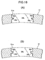
FIG. 18 . - In the first embodiment, the shape of the
recesses magnetic poles spacer 39, as well as the shape of theprojections 31b of theslits 31a in therotor body 31 are square, but the same effects can be achieved also by a triangular shape as shown inFIG. 18 (A) or an U-shape as shown inFIG. 18(B) . - Further, the first and second induction
magnetic poles recesses projections 31b, forming the projections on the side of the first and second inductionmagnetic poles spacer 39, and forming the recesses on the side of theslits 31a. However, if therecesses 38a are formed on the side of the first and second inductionmagnetic poles slits 31a. - Next, a third embodiment of the present invention will be described based on
FIG. 19 to FIG. 21 . - In the third embodiment,
grooves 39b extending in the circumferential direction are formed in the surface of thespacers 39 of theouter rotor 13,grooves 31d leading to thegrooves 39b of thespacers 39 are formed in the outer circumferential face of therotor body 31 of theouter rotor 13, and aring 59 made of a weak magnetic body is fitted in thegrooves - When the
outer rotor 13 is rotated, a centrifugal force acts on the first and second inductionmagnetic poles spacers 39, an intermediate portion of therotor body 31 in the axis L direction is deformed to bulge. However, the intermediate portion of therotor body 31 in the axis L direction is pressed by thering 59, thereby preventing the deformation. - Next, a fourth embodiment of the present invention will be described based on
FIG. 22 . - In the fourth embodiment, the first
permanent magnet 52L or the secondpermanent magnet 52R constituting a single magnetic pole of theinner rotor 14 is divided into two parts. In this case, in order for the two permanent magnets to constitute a single magnetic pole, it is necessary for the polarities of the two permanent magnets to match with each other. - In this case, θ0 corresponding to the electric angle 180° of the magnetic pole in the
inner rotor 14 is defined as an angle formed by two radial lines passing between adjacent pairs, when the twopermanent magnets - Next, a fifth example not being part of the present invention will be described based on
FIG. 23 . - In the above-described first to fourth embodiments, the present invention is applied to the rotating-type motor M, but in the fifth example, linear-motion type motor M (so-called linear motor) is shown.
- In this case, as shown in
FIG. 12 , a linear induction magnetic-pole row formed by the first and second inductionmagnetic poles second armatures permanent magnets second armatures - Then, as shown in
FIG. 23 , a distance L2 between opposite ends in the linear direction between the first and second inductionmagnetic poles permanent magnets permanent magnets 52L (or the secondpermanent magnets 52R) adjacent in the linear direction of the second magnetic-pole row through the first inductionmagnetic poles 38L (or second inductionmagnetic poles 38R) of the induction magnetic-pole row, thereby improving magnetic efficiency. - Next, a sixth example not being part of the present invention will be described based on
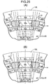
FIGS. 24 and25 . - In the sixth example a magnetic gear is shown, in which the first and
second stators permanent magnets second armatures inner rotor 14 and theouter rotor 13 is driven while the first andsecond stators inner rotor 14 is fixed, a driving force can be transmitted between the first andsecond stators outer rotor 13; if theouter rotor 13 is fixed, the driving force can be transmitted between the first andsecond stators inner rotor 14; and if the three are made rotatable, they can function as a differential device. - Also in this embodiment, as shown in
FIG. 25(A) , θ0 corresponding to the electric angle 180° of the first and secondpermanent magnets inner rotor 14 is set so that a relationship of 90 < θ1 ≤ θ2 is established with respect to an angle θ2 formed by two straight lines drawn from the axis L to opposite ends of the first and second inductionmagnetic poles permanent magnets - Similarly, as shown in
FIG. 25(B) , θ0 corresponding to the electric angle 180° of the first and secondpermanent magnets second stators magnetic poles permanent magnets - The motor M is illustrated in the embodiments, but the present invention is applicable to a motor which generates an electromotive force at a stator by fixing one of the outer-rotor and the inner rotor and rotating the other.
- Also, in the embodiments, the
armatures stators permanent magnets inner rotor 14 arranged inside in the radial direction, but their positional relationship may be reversed so that the stator having thearmature permanent magnets - In the embodiments, the
stators outer rotor 13 and theinner rotor 14 are arranged in the radial direction (radial arrangement), but they may be arranged in the axis L direction. That is, the stators having the armatures and the rotors having the permanent magnets may be arranged on opposite sides in the axis L direction of the rotor having the induction magnetic poles (axial arrangement). This arrangement is not part of the claimed invention. - Further, the
stators - Furthermore, the polar logarithms of the first and
second stators outer rotor 13 and theinner rotor 14 are not limited to those in the embodiments, and can be appropriately changed.
Claims (13)
- A motor comprising:annular stators (12L, 12R) arranged so as to surround an axis (L); a first rotor (14) rotatable around the axis (L); and a second rotor (13) arranged between the stator (12) and the first rotor (14), and rotatable around the axis (L),wherein the stators (12L, 12R) comprise a first armature row and a second armature row arranged in the axis (L) direction, the first armature row including a plurality of first armatures (21L) arranged in a circumferential direction and generating a first rotating magnetic field rotating along the circumferential direction by a magnetic pole generated at the plurality of first armatures (21L) upon supply of electric power, the second armature row including a plurality of second armatures (21R) arranged in the circumferential direction and generating a second rotating magnetic field rotating along the circumferential direction by a magnetic pole generated at the plurality of second armatures (21R) upon supply of electric power;wherein the first rotor (14) comprises a first permanent magnet row and a second permanent magnetic row arranged in the axis (L) direction, the first permanent magnet row including a plurality of first permanent magnets (52L) arranged so as to have magnetic poles with different polarities alternately with a predetermined pitch (P) in the circumferential direction, the second permanent magnetic row including a plurality of second permanent magnets (52R) arranged so as to have magnetic poles with different polarities alternately with the predetermined pitch (P) in the circumferential direction;wherein the second rotor (13) comprises a first induction magnetic-pole row and a second induction magnetic-pole row arranged in the axis (L) direction, the first induction magnetic-pole row including a plurality of first induction magnetic poles (38L) arranged with the predetermined pitch (P) in the circumferential direction and made of a soft magnetic body; and the second induction magnetic-pole row including a plurality of second induction magnetic poles (38R) arranged with the predetermined pitch (P) in the circumferential direction and made of a soft magnetic body; andwherein the first armature row and the first permanent magnet row are opposed to each other on opposite sides in the radial direction of the first induction magnetic-pole row, respectively, and the second armature row and the second permanent magnet row are opposed to each other on opposite sides in the radial direction of the second induction magnetic-pole row, respectively;whereina phase of a magnetic pole of the first permanent magnet row and a phase of the magnetic pole of the second permanent magnet row of the first rotor (14) are displaced from each other by a half of the predetermined pitch (P) in the circumferential direction, a phase of the polarity of the first rotating magnetic field and a phase of the polarity of the second rotating magnetic field of the stator (12) are displaced from each other by a half of the predetermined pitch (P) in the circumferential direction, and a phase of the first induction magnetic pole (38L) and a phase of the second induction magnetic pole (38R) of the second rotor (13) are matched with each other.
- The motor according to claim 1, wherein a plurality of slits (31a) extending linearly in the axis (L) direction are formed in a cylindrical rotor body (31) of the second rotor (13), and the first and second induction magnetic poles (38L, 38R) are fitted in the slits (31a).
- The motor according to claim 1 or 2, wherein the second rotor (13) is made of a non-magnetic body, and the plurality of induction magnetic poles (38L, 38R) is supported on the second rotor (13) at predetermined intervals in a circumferential direction, wherein the induction magnetic poles (38L, 38R) are embedded in the second rotor (13).
- The motor according to claim 3, wherein a part of each induction magnetic pole (38L, 38R) is exposed on an outer-circumferential surface of the second rotor (13).
- The motor according to claim 3 or 4, wherein the second rotor (13) is in a cylindrical shape, and a part of each induction magnetic pole (38L, 38R) is exposed on an inner-circumferential surface of the second rotor (13).
- The motor according to any of claims 3 to 5, wherein a face on which the second rotor (13) is brought into contact with the induction magnetic poles (38L, 38R) is in a shape which limits movement of the induction magnetic poles (38L, 38R) in the radial direction with respect to the second rotor (13).
- The motor according to claim 6, wherein movement of the induction magnetic poles (38L, 38R) in the radial direction with respect to the second rotor (13) is limited by engagement between projections provided on the second rotor (13) and recesses (38a) provided in each induction magnetic pole (38L, 38R).
- The motor according to any of claims 3 to 7, wherein the second rotor (13) comprises a plurality of slits (31a) extending in the axis (L) direction; and the plurality of induction magnetic poles (38L, 38R) and spacers (39) made of a non-magnetic body located between the induction magnetic poles (38L, 38R) adjacent in the axis (L) direction are embedded in the slits (31a).
- The motor according to claim 8, wherein a face on which the second rotor (13) is brought into contact with the spacer (39) is in a shape which limits movement of the spacer (39) in the radial direction with respect to the second rotor (13).
- The motor according to claim 8 or 9, wherein an outer circumferential face of the spacer (39) is covered by a ring (59) made of a non-magnetic body.
- The motor according to any of claims 3 to 10, further comprising a holder (41) for limiting movement of the induction magnetic poles (38L, 38R) in the axis (L) direction with respect to the second rotor (13).
- The motor according to any of claims 3 to 11, wherein the second rotor (13) further comprises a rotor body (31) in a bottomed cylindrical shape; a rotor cover (33) connected to the rotor body (31) so as to cover an opening of the rotor body (31); and rotating shafts (34, 36) are provided in bottom portions of the rotor body (31) and the rotor cover (33).
- The motor according to any of claims 1 to 12, wherein an angle (θ2) formed by opposite ends in the circumferential direction of the induction magnetic poles (38L, 38R) of the induction magnetic-pole rows with respect to the axis (L) is set smaller than at least one of a machine angle (θ1) corresponding to an electric angle 180° of the armatures (21L, 21R) and a machine angle (θ0) corresponding to the electric angle 180° of the magnetic poles (52L, 52R) of the permanent magnetic rows.
Applications Claiming Priority (5)
| Application Number | Priority Date | Filing Date | Title |
|---|---|---|---|
| JP2007026422 | 2007-02-06 | ||
| JP2007026423A JP2008193823A (en) | 2007-02-06 | 2007-02-06 | Rotor structure |
| JP2007026424 | 2007-02-06 | ||
| JP2007316189A JP4648378B2 (en) | 2007-02-06 | 2007-12-06 | Electric motor |
| PCT/JP2008/050865 WO2008096600A1 (en) | 2007-02-06 | 2008-01-23 | Electric motor, rotor structure, and magnetic machine |
Publications (3)
| Publication Number | Publication Date |
|---|---|
| EP2110933A1 EP2110933A1 (en) | 2009-10-21 |
| EP2110933A4 EP2110933A4 (en) | 2010-03-24 |
| EP2110933B1 true EP2110933B1 (en) | 2012-08-01 |
Family
ID=40943393
Family Applications (1)
| Application Number | Title | Priority Date | Filing Date |
|---|---|---|---|
| EP08703706A Not-in-force EP2110933B1 (en) | 2007-02-06 | 2008-01-23 | Motor, rotor structure and magnetic machine |
Country Status (8)
| Country | Link |
|---|---|
| US (1) | US20080238232A1 (en) |
| EP (1) | EP2110933B1 (en) |
| KR (1) | KR101121271B1 (en) |
| AU (1) | AU2008212433B2 (en) |
| BR (1) | BRPI0807008A2 (en) |
| CA (1) | CA2677411A1 (en) |
| MX (1) | MX2009008346A (en) |
| WO (1) | WO2008096600A1 (en) |
Families Citing this family (21)
| Publication number | Priority date | Publication date | Assignee | Title |
|---|---|---|---|---|
| US8294318B2 (en) * | 2007-12-26 | 2012-10-23 | Honda Motor Co., Ltd. | Electric motor and rotor for rotating electric machine |
| GB0810097D0 (en) * | 2008-06-03 | 2008-07-09 | Magnomatics Ltd | Magnetic gear |
| GB0808524D0 (en) * | 2008-05-12 | 2008-06-18 | Magnomatics Ltd | Magnetic pole-piece structure |
| IT1392883B1 (en) | 2008-09-03 | 2012-04-02 | Lenzi | METHOD FOR ASSEMBLY OF THE ROTOR OF A ROTATING ELECTRIC MACHINE |
| EP2479871B1 (en) * | 2011-01-19 | 2016-06-15 | GE Energy Power Conversion Technology Limited | Electrical machines |
| JP5350438B2 (en) * | 2011-06-29 | 2013-11-27 | 株式会社日立製作所 | Magnetic gear mechanism |
| JP5772322B2 (en) * | 2011-07-13 | 2015-09-02 | 株式会社豊田中央研究所 | Rotating electric machine with speed change mechanism |
| RU2475926C1 (en) * | 2011-07-29 | 2013-02-20 | Открытое акционерное общество "Научно-производственная корпорация "Космические системы мониторинга, информационно-управляющие и электромеханические комплексы имени А.Г. Иосифьяна" (ОАО "Корпорация "ВНИИЭМ") | Magnetoelectric machine rotor system |
| EP2555393B1 (en) * | 2011-08-01 | 2013-11-20 | Siemens Aktiengesellschaft | Magnet loading apparatus |
| DE112013001800T5 (en) * | 2012-03-30 | 2014-12-11 | Honda Motor Co., Ltd. | Electric circulating machine |
| CN104953780A (en) | 2012-08-03 | 2015-09-30 | 埃塞克科技有限公司 | Modular rotatable transverse flux electrical machine |
| US9559559B2 (en) | 2012-09-24 | 2017-01-31 | Eocycle Technologies Inc. | Transverse flux electrical machine stator with stator skew and assembly thereof |
| CA2829812A1 (en) | 2012-10-17 | 2014-04-17 | Eocycle Technologies Inc. | Transverse flux electrical machine rotor |
| US10739046B2 (en) * | 2014-06-17 | 2020-08-11 | Mitsubishi Electric Corporation | Compressor, refrigeration cycle apparatus, and air conditioner |
| GB2545154B (en) | 2015-08-24 | 2021-12-01 | Magnomatics Ltd | Magnetically geared apparatus and a pole piece for such apparatus |
| CN106921234A (en) * | 2017-05-16 | 2017-07-04 | 深圳市赫瑞科技有限公司 | A kind of magnetic gear outer rotor mounting structure |
| UA124412C2 (en) | 2017-12-22 | 2021-09-15 | Євгеній Віталійович Мушинський | CONTRACTOR SYNCHRONOUS ELECTROMECHANICAL CONVERTER |
| US11522436B2 (en) | 2019-10-15 | 2022-12-06 | Darrell Schmidt Enterprises, Inc. | Permanently magnetized enhanced generator |
| US11296588B2 (en) | 2019-10-15 | 2022-04-05 | Darrell Schmidt Enterprises, Inc. | Magnetic coupler |
| CN115380460A (en) * | 2020-04-16 | 2022-11-22 | 三菱电机株式会社 | Rotating electrical machine |
| US11689088B2 (en) | 2020-08-12 | 2023-06-27 | Robert Willoughby Garrett, IV | Movable permanent magnet stator electric motor |
Citations (1)
| Publication number | Priority date | Publication date | Assignee | Title |
|---|---|---|---|---|
| EP2015428A1 (en) * | 2006-08-09 | 2009-01-14 | HONDA MOTOR CO., Ltd. | Motor |
Family Cites Families (27)
| Publication number | Priority date | Publication date | Assignee | Title |
|---|---|---|---|---|
| JPH04331445A (en) * | 1991-05-01 | 1992-11-19 | Honda Motor Co Ltd | Induction motor |
| JPH0746807A (en) * | 1993-05-21 | 1995-02-14 | Toshiba Corp | Rotor of rotating electric machine |
| JP3427511B2 (en) | 1994-10-11 | 2003-07-22 | 株式会社デンソー | Dual-shaft output motor |
| JP3190558B2 (en) * | 1995-12-25 | 2001-07-23 | 三菱電機株式会社 | Method of manufacturing rotor of cage induction machine |
| JP3051340B2 (en) * | 1996-06-18 | 2000-06-12 | オークマ株式会社 | Synchronous motor |
| KR19990065127A (en) * | 1998-01-08 | 1999-08-05 | 구자홍 | Rotor of embedded permanent magnet synchronous motor |
| JPH11341757A (en) | 1998-05-21 | 1999-12-10 | Toyota Motor Corp | Motor, power transmission apparatus, and hybrid vehicle |
| US6274960B1 (en) * | 1998-09-29 | 2001-08-14 | Kabushiki Kaisha Toshiba | Reluctance type rotating machine with permanent magnets |
| US6590312B1 (en) * | 1999-11-18 | 2003-07-08 | Denso Corporation | Rotary electric machine having a permanent magnet stator and permanent magnet rotor |
| JP4269544B2 (en) * | 2000-09-14 | 2009-05-27 | 株式会社デンソー | Multi-rotor synchronous machine |
| JP2002122203A (en) * | 2000-10-17 | 2002-04-26 | Minebea Co Ltd | Linear actuator |
| JP2002136094A (en) * | 2000-10-30 | 2002-05-10 | Minebea Co Ltd | Stepping motor |
| US6774521B2 (en) * | 2001-05-16 | 2004-08-10 | Koyo Seiko Co., Ltd. | Brushless DC motor |
| JP3724416B2 (en) * | 2001-11-27 | 2005-12-07 | 株式会社デンソー | Axial division hybrid magnetic pole type brushless rotating electrical machine |
| US7064466B2 (en) * | 2001-11-27 | 2006-06-20 | Denso Corporation | Brushless rotary electric machine having tandem rotary cores |
| GB0208565D0 (en) * | 2002-04-13 | 2002-05-22 | Rolls Royce Plc | A compact electrical machine |
| KR20050025339A (en) * | 2002-07-10 | 2005-03-14 | 터보코 인코포레이티드 | Device to relieve thrust load in a rotor-bearing system using permanent magnets |
| JP4318959B2 (en) * | 2003-05-21 | 2009-08-26 | 本田技研工業株式会社 | Permanent magnet rotor and brushless motor |
| US6924574B2 (en) * | 2003-05-30 | 2005-08-02 | Wisconsin Alumni Research Foundation | Dual-rotor, radial-flux, toroidally-wound, permanent-magnet machine |
| DE10354604B4 (en) * | 2003-11-21 | 2016-10-13 | Gesellschaft für Aufladetechnik und Spindelbau mbH | Infinitely variable, magnetodynamic transmission |
| JP4069859B2 (en) * | 2003-12-15 | 2008-04-02 | 日産自動車株式会社 | Structure of rotating electrical machine |
| US7400077B2 (en) * | 2004-03-23 | 2008-07-15 | Electric Motor Development, Inc. | Electric motor having multiple armatures |
| JP4274473B2 (en) * | 2004-06-14 | 2009-06-10 | ミネベア株式会社 | Actuator |
| US7692357B2 (en) * | 2004-12-16 | 2010-04-06 | General Electric Company | Electrical machines and assemblies including a yokeless stator with modular lamination stacks |
| JP4508895B2 (en) | 2005-02-02 | 2010-07-21 | 株式会社オーディオテクニカ | Hanging microphone |
| KR100652596B1 (en) * | 2005-04-11 | 2006-12-01 | 엘지전자 주식회사 | Twin magnet hybride induction motor |
| JP4260799B2 (en) * | 2005-12-02 | 2009-04-30 | 本田技研工業株式会社 | Electric motor and method for driving electric motor |
-
2008
- 2008-01-23 CA CA002677411A patent/CA2677411A1/en not_active Abandoned
- 2008-01-23 BR BRPI0807008-3A patent/BRPI0807008A2/en not_active IP Right Cessation
- 2008-01-23 AU AU2008212433A patent/AU2008212433B2/en not_active Ceased
- 2008-01-23 WO PCT/JP2008/050865 patent/WO2008096600A1/en active Application Filing
- 2008-01-23 MX MX2009008346A patent/MX2009008346A/en active IP Right Grant
- 2008-01-23 KR KR1020097017237A patent/KR101121271B1/en not_active IP Right Cessation
- 2008-01-23 EP EP08703706A patent/EP2110933B1/en not_active Not-in-force
- 2008-02-06 US US12/068,444 patent/US20080238232A1/en not_active Abandoned
Patent Citations (1)
| Publication number | Priority date | Publication date | Assignee | Title |
|---|---|---|---|---|
| EP2015428A1 (en) * | 2006-08-09 | 2009-01-14 | HONDA MOTOR CO., Ltd. | Motor |
Also Published As
| Publication number | Publication date |
|---|---|
| EP2110933A4 (en) | 2010-03-24 |
| CA2677411A1 (en) | 2008-08-14 |
| AU2008212433A1 (en) | 2008-08-14 |
| WO2008096600A1 (en) | 2008-08-14 |
| KR20090104869A (en) | 2009-10-06 |
| BRPI0807008A2 (en) | 2014-04-22 |
| US20080238232A1 (en) | 2008-10-02 |
| KR101121271B1 (en) | 2012-03-26 |
| AU2008212433B2 (en) | 2011-08-11 |
| EP2110933A1 (en) | 2009-10-21 |
| MX2009008346A (en) | 2009-08-20 |
Similar Documents
| Publication | Publication Date | Title |
|---|---|---|
| EP2110933B1 (en) | Motor, rotor structure and magnetic machine | |
| EP2226924B1 (en) | Motor and rotor for dynamo-electric machine | |
| EP0558746B1 (en) | Rotor of brushless motor | |
| CN101779366B (en) | Axial gap type motor | |
| EP1990895B1 (en) | Stress distributing permanent magnet rotor geometry for electric machines | |
| WO2015146210A1 (en) | Permanent magnet rotating electric machine and method for manufacturing same | |
| EP2141784B1 (en) | Rotor for rotating machine | |
| JP2009509490A (en) | Teeth module for permanent magnet excitation primary pole member of electric machine | |
| CN116057820A (en) | Rotary electric machine and method for manufacturing stator | |
| CN101589537A (en) | Electric motor, rotor structure, and magnetic machine | |
| JP5691451B2 (en) | Rotor for rotating electrical machines | |
| RU2435282C2 (en) | Engine, rotor structure and magnetic machine | |
| EP4096062A1 (en) | Stator and rotating electrical machine using the same | |
| JP4801824B2 (en) | Magnetic machine | |
| JP2008193823A (en) | Rotor structure | |
| JP4680980B2 (en) | Electric motor | |
| JP4482900B2 (en) | Axial gap type motor | |
| WO2023118983A1 (en) | Reduction of cogging torque in two-stator permanent magnet generators with an intermediate rotor radial flux. | |
| JP4648378B2 (en) | Electric motor | |
| JP4767997B2 (en) | Rotating electric machine rotor and electric motor | |
| JP2008289227A (en) | Rotor for rotating electric machine | |
| JP4691087B2 (en) | Electric motor | |
| JPH0426350A (en) | Brushless motor | |
| KR20210149580A (en) | Coggingless Coreless BLDC Motor | |
| KR20220101709A (en) | rotating electric machine |
Legal Events
| Date | Code | Title | Description |
|---|---|---|---|
| PUAI | Public reference made under article 153(3) epc to a published international application that has entered the european phase |
Free format text: ORIGINAL CODE: 0009012 |
|
| 17P | Request for examination filed |
Effective date: 20090806 |
|
| AK | Designated contracting states |
Kind code of ref document: A1 Designated state(s): AT BE BG CH CY CZ DE DK EE ES FI FR GB GR HR HU IE IS IT LI LT LU LV MC MT NL NO PL PT RO SE SI SK TR |
|
| A4 | Supplementary search report drawn up and despatched |
Effective date: 20100218 |
|
| 17Q | First examination report despatched |
Effective date: 20100303 |
|
| DAX | Request for extension of the european patent (deleted) | ||
| RTI1 | Title (correction) |
Free format text: MOTOR, ROTOR STRUCTURE AND MAGNETIC MACHINE |
|
| GRAP | Despatch of communication of intention to grant a patent |
Free format text: ORIGINAL CODE: EPIDOSNIGR1 |
|
| GRAS | Grant fee paid |
Free format text: ORIGINAL CODE: EPIDOSNIGR3 |
|
| GRAA | (expected) grant |
Free format text: ORIGINAL CODE: 0009210 |
|
| AK | Designated contracting states |
Kind code of ref document: B1 Designated state(s): AT BE BG CH CY CZ DE DK EE ES FI FR GB GR HR HU IE IS IT LI LT LU LV MC MT NL NO PL PT RO SE SI SK TR |
|
| REG | Reference to a national code |
Ref country code: GB Ref legal event code: FG4D |
|
| REG | Reference to a national code |
Ref country code: CH Ref legal event code: EP Ref country code: AT Ref legal event code: REF Ref document number: 569100 Country of ref document: AT Kind code of ref document: T Effective date: 20120815 |
|
| REG | Reference to a national code |
Ref country code: IE Ref legal event code: FG4D |
|
| REG | Reference to a national code |
Ref country code: DE Ref legal event code: R096 Ref document number: 602008017566 Country of ref document: DE Effective date: 20120927 |
|
| REG | Reference to a national code |
Ref country code: NL Ref legal event code: VDEP Effective date: 20120801 |
|
| REG | Reference to a national code |
Ref country code: AT Ref legal event code: MK05 Ref document number: 569100 Country of ref document: AT Kind code of ref document: T Effective date: 20120801 |
|
| REG | Reference to a national code |
Ref country code: LT Ref legal event code: MG4D Effective date: 20120801 |
|
| PG25 | Lapsed in a contracting state [announced via postgrant information from national office to epo] |
Ref country code: FI Free format text: LAPSE BECAUSE OF FAILURE TO SUBMIT A TRANSLATION OF THE DESCRIPTION OR TO PAY THE FEE WITHIN THE PRESCRIBED TIME-LIMIT Effective date: 20120801 Ref country code: IS Free format text: LAPSE BECAUSE OF FAILURE TO SUBMIT A TRANSLATION OF THE DESCRIPTION OR TO PAY THE FEE WITHIN THE PRESCRIBED TIME-LIMIT Effective date: 20121201 Ref country code: NO Free format text: LAPSE BECAUSE OF FAILURE TO SUBMIT A TRANSLATION OF THE DESCRIPTION OR TO PAY THE FEE WITHIN THE PRESCRIBED TIME-LIMIT Effective date: 20121101 Ref country code: LT Free format text: LAPSE BECAUSE OF FAILURE TO SUBMIT A TRANSLATION OF THE DESCRIPTION OR TO PAY THE FEE WITHIN THE PRESCRIBED TIME-LIMIT Effective date: 20120801 Ref country code: HR Free format text: LAPSE BECAUSE OF FAILURE TO SUBMIT A TRANSLATION OF THE DESCRIPTION OR TO PAY THE FEE WITHIN THE PRESCRIBED TIME-LIMIT Effective date: 20120801 Ref country code: AT Free format text: LAPSE BECAUSE OF FAILURE TO SUBMIT A TRANSLATION OF THE DESCRIPTION OR TO PAY THE FEE WITHIN THE PRESCRIBED TIME-LIMIT Effective date: 20120801 Ref country code: CY Free format text: LAPSE BECAUSE OF FAILURE TO SUBMIT A TRANSLATION OF THE DESCRIPTION OR TO PAY THE FEE WITHIN THE PRESCRIBED TIME-LIMIT Effective date: 20120801 |
|
| PG25 | Lapsed in a contracting state [announced via postgrant information from national office to epo] |
Ref country code: PL Free format text: LAPSE BECAUSE OF FAILURE TO SUBMIT A TRANSLATION OF THE DESCRIPTION OR TO PAY THE FEE WITHIN THE PRESCRIBED TIME-LIMIT Effective date: 20120801 Ref country code: SI Free format text: LAPSE BECAUSE OF FAILURE TO SUBMIT A TRANSLATION OF THE DESCRIPTION OR TO PAY THE FEE WITHIN THE PRESCRIBED TIME-LIMIT Effective date: 20120801 Ref country code: GR Free format text: LAPSE BECAUSE OF FAILURE TO SUBMIT A TRANSLATION OF THE DESCRIPTION OR TO PAY THE FEE WITHIN THE PRESCRIBED TIME-LIMIT Effective date: 20121102 Ref country code: PT Free format text: LAPSE BECAUSE OF FAILURE TO SUBMIT A TRANSLATION OF THE DESCRIPTION OR TO PAY THE FEE WITHIN THE PRESCRIBED TIME-LIMIT Effective date: 20121203 Ref country code: LV Free format text: LAPSE BECAUSE OF FAILURE TO SUBMIT A TRANSLATION OF THE DESCRIPTION OR TO PAY THE FEE WITHIN THE PRESCRIBED TIME-LIMIT Effective date: 20120801 Ref country code: BE Free format text: LAPSE BECAUSE OF FAILURE TO SUBMIT A TRANSLATION OF THE DESCRIPTION OR TO PAY THE FEE WITHIN THE PRESCRIBED TIME-LIMIT Effective date: 20120801 Ref country code: SE Free format text: LAPSE BECAUSE OF FAILURE TO SUBMIT A TRANSLATION OF THE DESCRIPTION OR TO PAY THE FEE WITHIN THE PRESCRIBED TIME-LIMIT Effective date: 20120801 |
|
| PG25 | Lapsed in a contracting state [announced via postgrant information from national office to epo] |
Ref country code: NL Free format text: LAPSE BECAUSE OF FAILURE TO SUBMIT A TRANSLATION OF THE DESCRIPTION OR TO PAY THE FEE WITHIN THE PRESCRIBED TIME-LIMIT Effective date: 20120801 |
|
| PG25 | Lapsed in a contracting state [announced via postgrant information from national office to epo] |
Ref country code: EE Free format text: LAPSE BECAUSE OF FAILURE TO SUBMIT A TRANSLATION OF THE DESCRIPTION OR TO PAY THE FEE WITHIN THE PRESCRIBED TIME-LIMIT Effective date: 20120801 Ref country code: RO Free format text: LAPSE BECAUSE OF FAILURE TO SUBMIT A TRANSLATION OF THE DESCRIPTION OR TO PAY THE FEE WITHIN THE PRESCRIBED TIME-LIMIT Effective date: 20120801 Ref country code: CZ Free format text: LAPSE BECAUSE OF FAILURE TO SUBMIT A TRANSLATION OF THE DESCRIPTION OR TO PAY THE FEE WITHIN THE PRESCRIBED TIME-LIMIT Effective date: 20120801 Ref country code: DK Free format text: LAPSE BECAUSE OF FAILURE TO SUBMIT A TRANSLATION OF THE DESCRIPTION OR TO PAY THE FEE WITHIN THE PRESCRIBED TIME-LIMIT Effective date: 20120801 Ref country code: ES Free format text: LAPSE BECAUSE OF FAILURE TO SUBMIT A TRANSLATION OF THE DESCRIPTION OR TO PAY THE FEE WITHIN THE PRESCRIBED TIME-LIMIT Effective date: 20121112 |
|
| PGFP | Annual fee paid to national office [announced via postgrant information from national office to epo] |
Ref country code: GB Payment date: 20130109 Year of fee payment: 6 Ref country code: FR Payment date: 20130225 Year of fee payment: 6 |
|
| PG25 | Lapsed in a contracting state [announced via postgrant information from national office to epo] |
Ref country code: IT Free format text: LAPSE BECAUSE OF FAILURE TO SUBMIT A TRANSLATION OF THE DESCRIPTION OR TO PAY THE FEE WITHIN THE PRESCRIBED TIME-LIMIT Effective date: 20120801 Ref country code: SK Free format text: LAPSE BECAUSE OF FAILURE TO SUBMIT A TRANSLATION OF THE DESCRIPTION OR TO PAY THE FEE WITHIN THE PRESCRIBED TIME-LIMIT Effective date: 20120801 |
|
| PLBE | No opposition filed within time limit |
Free format text: ORIGINAL CODE: 0009261 |
|
| STAA | Information on the status of an ep patent application or granted ep patent |
Free format text: STATUS: NO OPPOSITION FILED WITHIN TIME LIMIT |
|
| 26N | No opposition filed |
Effective date: 20130503 |
|
| PG25 | Lapsed in a contracting state [announced via postgrant information from national office to epo] |
Ref country code: BG Free format text: LAPSE BECAUSE OF FAILURE TO SUBMIT A TRANSLATION OF THE DESCRIPTION OR TO PAY THE FEE WITHIN THE PRESCRIBED TIME-LIMIT Effective date: 20121101 |
|
| PGFP | Annual fee paid to national office [announced via postgrant information from national office to epo] |
Ref country code: DE Payment date: 20130328 Year of fee payment: 6 |
|
| REG | Reference to a national code |
Ref country code: DE Ref legal event code: R097 Ref document number: 602008017566 Country of ref document: DE Effective date: 20130503 |
|
| PG25 | Lapsed in a contracting state [announced via postgrant information from national office to epo] |
Ref country code: MC Free format text: LAPSE BECAUSE OF NON-PAYMENT OF DUE FEES Effective date: 20130131 |
|
| REG | Reference to a national code |
Ref country code: CH Ref legal event code: PL |
|
| REG | Reference to a national code |
Ref country code: IE Ref legal event code: MM4A |
|
| PG25 | Lapsed in a contracting state [announced via postgrant information from national office to epo] |
Ref country code: LI Free format text: LAPSE BECAUSE OF NON-PAYMENT OF DUE FEES Effective date: 20130131 Ref country code: CH Free format text: LAPSE BECAUSE OF NON-PAYMENT OF DUE FEES Effective date: 20130131 |
|
| PG25 | Lapsed in a contracting state [announced via postgrant information from national office to epo] |
Ref country code: IE Free format text: LAPSE BECAUSE OF NON-PAYMENT OF DUE FEES Effective date: 20130123 |
|
| PG25 | Lapsed in a contracting state [announced via postgrant information from national office to epo] |
Ref country code: MT Free format text: LAPSE BECAUSE OF FAILURE TO SUBMIT A TRANSLATION OF THE DESCRIPTION OR TO PAY THE FEE WITHIN THE PRESCRIBED TIME-LIMIT Effective date: 20120801 |
|
| REG | Reference to a national code |
Ref country code: DE Ref legal event code: R119 Ref document number: 602008017566 Country of ref document: DE |
|
| GBPC | Gb: european patent ceased through non-payment of renewal fee |
Effective date: 20140123 |
|
| PG25 | Lapsed in a contracting state [announced via postgrant information from national office to epo] |
Ref country code: DE Free format text: LAPSE BECAUSE OF NON-PAYMENT OF DUE FEES Effective date: 20140801 |
|
| REG | Reference to a national code |
Ref country code: FR Ref legal event code: ST Effective date: 20140930 |
|
| REG | Reference to a national code |
Ref country code: DE Ref legal event code: R119 Ref document number: 602008017566 Country of ref document: DE Effective date: 20140801 |
|
| PG25 | Lapsed in a contracting state [announced via postgrant information from national office to epo] |
Ref country code: GB Free format text: LAPSE BECAUSE OF NON-PAYMENT OF DUE FEES Effective date: 20140123 Ref country code: FR Free format text: LAPSE BECAUSE OF NON-PAYMENT OF DUE FEES Effective date: 20140131 |
|
| PG25 | Lapsed in a contracting state [announced via postgrant information from national office to epo] |
Ref country code: TR Free format text: LAPSE BECAUSE OF FAILURE TO SUBMIT A TRANSLATION OF THE DESCRIPTION OR TO PAY THE FEE WITHIN THE PRESCRIBED TIME-LIMIT Effective date: 20120801 |
|
| PG25 | Lapsed in a contracting state [announced via postgrant information from national office to epo] |
Ref country code: LU Free format text: LAPSE BECAUSE OF NON-PAYMENT OF DUE FEES Effective date: 20130123 Ref country code: HU Free format text: LAPSE BECAUSE OF FAILURE TO SUBMIT A TRANSLATION OF THE DESCRIPTION OR TO PAY THE FEE WITHIN THE PRESCRIBED TIME-LIMIT; INVALID AB INITIO Effective date: 20080123 |