EP0558746B1 - Rotor of brushless motor - Google Patents
Rotor of brushless motor Download PDFInfo
- Publication number
- EP0558746B1 EP0558746B1 EP91912495A EP91912495A EP0558746B1 EP 0558746 B1 EP0558746 B1 EP 0558746B1 EP 91912495 A EP91912495 A EP 91912495A EP 91912495 A EP91912495 A EP 91912495A EP 0558746 B1 EP0558746 B1 EP 0558746B1
- Authority
- EP
- European Patent Office
- Prior art keywords
- permanent magnets
- rotor
- field permanent
- permanent magnet
- magnetic poles
- Prior art date
- Legal status (The legal status is an assumption and is not a legal conclusion. Google has not performed a legal analysis and makes no representation as to the accuracy of the status listed.)
- Expired - Lifetime
Links
- 239000000463 material Substances 0.000 claims description 5
- 230000000694 effects Effects 0.000 claims description 2
- 230000004907 flux Effects 0.000 abstract description 14
- 239000000696 magnetic material Substances 0.000 abstract 1
- 230000005284 excitation Effects 0.000 description 5
- 229910000976 Electrical steel Inorganic materials 0.000 description 4
- 238000004519 manufacturing process Methods 0.000 description 3
- 150000003376 silicon Chemical class 0.000 description 2
- 238000010276 construction Methods 0.000 description 1
- 238000003780 insertion Methods 0.000 description 1
- 230000037431 insertion Effects 0.000 description 1
- 238000000034 method Methods 0.000 description 1
- 230000002093 peripheral effect Effects 0.000 description 1
- 230000035699 permeability Effects 0.000 description 1
- 238000003825 pressing Methods 0.000 description 1
- 229910000859 α-Fe Inorganic materials 0.000 description 1
Images


Classifications
-
- H—ELECTRICITY
- H02—GENERATION; CONVERSION OR DISTRIBUTION OF ELECTRIC POWER
- H02K—DYNAMO-ELECTRIC MACHINES
- H02K1/00—Details of the magnetic circuit
- H02K1/06—Details of the magnetic circuit characterised by the shape, form or construction
- H02K1/22—Rotating parts of the magnetic circuit
- H02K1/27—Rotor cores with permanent magnets
- H02K1/2706—Inner rotors
- H02K1/272—Inner rotors the magnetisation axis of the magnets being perpendicular to the rotor axis
- H02K1/274—Inner rotors the magnetisation axis of the magnets being perpendicular to the rotor axis the rotor consisting of two or more circumferentially positioned magnets
- H02K1/2746—Inner rotors the magnetisation axis of the magnets being perpendicular to the rotor axis the rotor consisting of two or more circumferentially positioned magnets the rotor consisting of magnets arranged with the same polarity, e.g. consequent pole type
Definitions
- This invention relates to a brushless motor which is of high efficiency and can be easily manufactured, and particularly to a rotor of such a brushless motor.
- the brushless motor generally comprises a cylindrical rotor and permanent magnets made of ferrite or the like arranged on the outer peripheral surface thereof.
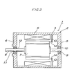
- a typical brushless motor 1 of prior art has a motor casing (i.e., stator) 2 comprising a cylindrical side wall 3, and front end plate 4 and a rear plate 5 both serving to block up opposite ends of the side wall 3, respectively.
- a motor casing i.e., stator 2
- front end plate 4 and a rear plate 5 both serving to block up opposite ends of the side wall 3, respectively.
- a rotor 7 is concentrically provided with a rotatable shaft 8 fixed thereto.
- the rotatable shaft 8 projects from opposite ends of the rotor 7 so as to be rotatably supported at one end in a bearing 10 carried by the rear end plate 5 and at the other end in a bearing 12 carried by the front plate 4 of the motor casing 2.
- a bearing 10 carried by the rear end plate 5
- a bearing 12 carried by the front plate 4 of the motor casing 2.
- annular member 13 adapted to hold a plurality of magnetic pole sensors 14 so that these sensors 14 are properly positioned closely adjacent one end surface of the rotor 7.
- the rotor including permanent magnets for brushless motor generally comprises a yoke provided with slots serving to receive field permanent magnets.
- a conventional rotor 20 provided with the permanent magnets is isometrically shown with a yoke 22 formed from a plurality of integrally laminated silicon steel sheets 21.
- the yoke 22 has four magnetic poles 23 projecting radially outward and slots 24 adjacent outer ends of the respective magnetic poles to receive the respective field permanent magnets 25.
- the respective magnetic poles 23 are magnetized by these field permanent magnets 25.
- Fig. 5 of the attached drawing is a fragmentary sectional view showing the permanent magnet rotor 20 in an enlarged scale. As shown, the field permanent magnets 25 are inserted into the respective slots 24 so that N- and S-poles alternately look outward.
- the field permanent magnets 25 generate magnetic flux extending from the respective N-poles through the yoke 22 and the external space surrounding the permanent magnet rotor 20. respectively, to the respective S-poles.
- the magnetic flux passing through the external space surrounding the permanent magnet rotor 20 intersects the stator provided around the rotor and interacts with electric current flowing through excitation coils of the stator to drive the permanent magnet rotor.
- the yoke of the conventional permanent magnet rotor is formed with bridges 26 adapted to connect the outer ends with the bases of the respective magnetic poles. More specifically, as seen in Fig. 5, portions of the yoke 22 define the bridges 26 connecting the outer ends with the bases of the respective magnetic poles 23. A part of the magnetic flux which exits from each field permanent magnet 25 passes through the bridges 26 and reaches the S-pole of the same field permanent magnet 25. This magnetic flux passing through the bridges 26 does not contribute to rotational drive of the rotor and an efficiency of the field permanent magnets is correspondingly deteriorated.
- each field permanent magnet 25 of elongate configuration must be inserted into the relatively narrow slot and therefore the field permanent magnet 25 has sometimes been liable to be damaged during this inserting operation.
- the resinous molded material or the die cast material is used to connect the auxiliary yokes each defining the outer end of the magnetic pole with the main yoke defining the bases of the respective magnetic poles so that the entire magnetic flux generated from the field permanent magnets pass through the external space around the rotor and then reaches the adjacent magnetic poles. Consequently, the entire magnetic flux generated from the field permanent magnets intersects the stator provided around the rotor and interacts with electric current flowing through the excitation coils, effectively contributing to the rotation of the rotor.
- the permanent magnet rotor according to the invention has the main yoke, field permanent magnets and auxiliary yokes mounted as piled, so that the field permanent magnets are not required to be inserted into a narrow slot, thereby capable of completely preventing the permanent magnets from being damaged during inserting.
- FIG. 1 shows a permanent magnet rotor constructed in accordance with the invention.
- a permanent magnet rotor 51 centrally has a main yoke 53 comprising a plurality of integrally laminated silicon steel sheets 52.
- Each of these silicon steel sheets 52 has a plurality of rectangular recesses 54 formed by pressing process so that these silicon steel sheets may be caulked together by forcing the recesses 54 into engagement with one another and thereby integrated into the main yoke 53.
- the main yoke 53 is centrally formed with an opening 55 axially extending therethrough to receive a rotatable shaft 56 which has, in turn, a key by means of which the rotatable shaft 56 is rotated integrally with the main yoke 53.
- the main yoke 53 has along its outer periphery a pair of magnetic poles 57 projecting radially outward and a pair of magnet seats 58.
- the magnet seats 58 are formed symmetrically with respect to the rotatable shaft 56 and carry thereon a pair of field permanent magnets 59, respectively, with their magnetic poles of the same polarity being opposed to each other.
- the field permanent magnets 59 are shaped in flat boards and mounted on the magnet seats with their N-poles being opposed to each other.
- auxiliary yokes 61 each functioning as a magnetic pole 60.
- a space defined between each pair of the adjacent magnetic poles 57, 60 is filled with resinous molded member or die cast member to form a molded portion 62 which integrally assembles the main yoke 53, the field permanent magnet 59 and the auxiliary yoke 61.
- Outer peripheries of the respective molded portions 62 are formed in continuity with the magnetic pole surface of the magnetic poles 57, 60 so as to form together a cylindrical outer periphery of the permanent magnet rotor 51.
- Fig. 2 is a fragmentary sectional view showing the permanent magnet rotor 51 in an enlarged scale.
- the main yoke 53 has joint surfaces 63 destined to be in contact with the respective molded portions 62 between the magnetic poles 57 and the magnet seats 58, respectively.
- Each joint surface 63 is formed with a dovetail 64 adapted to be engaged with the associated molded portion 62.
- each auxiliary yoke 61 has, between its magnetic pole surface and its surface contacting the associated field permanent magnet 59, a joint surface 65 destined to be in contact with the associated molded portion 62.
- Each joint surface 65 is formed with a dovetail 66 adapted to be engaged with the associated molded portion 62.
- liquefied material to be molded is poured into a space defined between the main yoke 53 and the auxiliary yokes 61 and simultaneously into the grooves of the respective dovetails 64, 66.
- the main yoke 53 and the auxiliary yokes 61 are engaged with the molded portions 62 along the respective dovetails 64, 66 so as to hold the field permanent magnets 59 therebetween.
- Such a construction is effective to prevent the field permanent magnets 59 as well as the auxiliary yokes 61 from centrifugally flying off during its operation.
- the field permanent magnets 59 are arranged with their N-poles being opposed to each other and, in consequence, the magnetic flux generated from these field permanent magnets 59 describes, under the mutual repulsing effect of the opposing magnetic poles, lines extending from the magnetic poles of the main yoke 53 through the external space around the permanent magnet rotor 51 to the magnetic poles 60 of the auxiliary yokes 61.
- the opposite end surfaces of each field permanent magnet 59 extending between the both poles thereof are contiguous to the molded portions 62 of low magnetic permeability and, consequently, no magnetic flux is short-circuited through the molded portions 62 to the S-poles. Namely, the entire magnetic flux generated from the field permanent magnets 59 intersects the stator (not shown) provided around the permanent magnet rotor 51 and effectively contributes to rotation of the rotor 51.
- the invention has been described in connection with the specific embodiment so constructed that the field permanent magnets are arranged with their magnetic poles of the same polarity being opposed to each other and mutual repulsion of these magnetic poles generates the magnetic poles along the outer periphery of the permanent magnet rotor, the number of which corresponds to twice the number of the permanent magnets, the invention is not limited to such a permanent magnet rotor but applicable also to the conventional permanent magnet rotor having the same number of field permanent magnets as the number of magnetic poles. While this embodiment of permanent magnet rotor has four magnetic poles, the invention is obviously applicable also to the permanent magnet rotor having any number of magnetic poles.
- the permanent magnet rotor of the invention it is unnecessary for the permanent magnet rotor of the invention to insert the permanent magnets of elongate configuration into the narrow slots and, as a result, damage of the permanent magnets possibly encountered by the prior art during the insertion of the permanent magnets can be perfectly avoided. Correspondingly, manufacturing of the permanent magnet rotor can be facilitated.
Landscapes
- Engineering & Computer Science (AREA)
- Power Engineering (AREA)
- Permanent Field Magnets Of Synchronous Machinery (AREA)
- Iron Core Of Rotating Electric Machines (AREA)
- Permanent Magnet Type Synchronous Machine (AREA)
Abstract
Description
- This invention relates to a brushless motor which is of high efficiency and can be easily manufactured, and particularly to a rotor of such a brushless motor.
- The brushless motor generally comprises a cylindrical rotor and permanent magnets made of ferrite or the like arranged on the outer peripheral surface thereof.
- As shown in Fig. 3 of the attached drawing, a typical
brushless motor 1 of prior art has a motor casing (i.e., stator) 2 comprising acylindrical side wall 3, andfront end plate 4 and arear plate 5 both serving to block up opposite ends of theside wall 3, respectively. Inside theside wall 3, there are provided a plurality ofexcitation coils 6 arranged to define a cylindrical array and fixed to the inner surface of theside wall 3. Arotor 7 is concentrically provided with arotatable shaft 8 fixed thereto. Therotatable shaft 8 projects from opposite ends of therotor 7 so as to be rotatably supported at one end in abearing 10 carried by therear end plate 5 and at the other end in abearing 12 carried by thefront plate 4 of themotor casing 2. There is provided inside theside wall 3 of themotor casing 2 anannular member 13 adapted to hold a plurality ofmagnetic pole sensors 14 so that thesesensors 14 are properly positioned closely adjacent one end surface of therotor 7. - The rotor including permanent magnets for brushless motor generally comprises a yoke provided with slots serving to receive field permanent magnets.
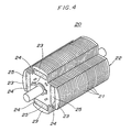
- Referring to Fig. 4 of the attached drawing, a
conventional rotor 20 provided with the permanent magnets is isometrically shown with ayoke 22 formed from a plurality of integrally laminatedsilicon steel sheets 21. Theyoke 22 has fourmagnetic poles 23 projecting radially outward andslots 24 adjacent outer ends of the respective magnetic poles to receive the respective fieldpermanent magnets 25. The respectivemagnetic poles 23 are magnetized by these fieldpermanent magnets 25. Fig. 5 of the attached drawing is a fragmentary sectional view showing thepermanent magnet rotor 20 in an enlarged scale. As shown, the fieldpermanent magnets 25 are inserted into therespective slots 24 so that N- and S-poles alternately look outward. With a consequence, the fieldpermanent magnets 25 generate magnetic flux extending from the respective N-poles through theyoke 22 and the external space surrounding thepermanent magnet rotor 20. respectively, to the respective S-poles. The magnetic flux passing through the external space surrounding thepermanent magnet rotor 20 intersects the stator provided around the rotor and interacts with electric current flowing through excitation coils of the stator to drive the permanent magnet rotor. - The yoke of the conventional permanent magnet rotor is formed with
bridges 26 adapted to connect the outer ends with the bases of the respective magnetic poles. More specifically, as seen in Fig. 5, portions of theyoke 22 define thebridges 26 connecting the outer ends with the bases of the respectivemagnetic poles 23. A part of the magnetic flux which exits from each fieldpermanent magnet 25 passes through thebridges 26 and reaches the S-pole of the same fieldpermanent magnet 25. This magnetic flux passing through thebridges 26 does not contribute to rotational drive of the rotor and an efficiency of the field permanent magnets is correspondingly deteriorated. - Furthermore, with the conventional permanent magnet rotor, each field
permanent magnet 25 of elongate configuration must be inserted into the relatively narrow slot and therefore the fieldpermanent magnet 25 has sometimes been liable to be damaged during this inserting operation. - Accordingly, it is an object of the invention to provide a permanent magnet rotor of a simplified structure which is able to utilize the entire magnetic flux generated from the field permanent magnets for rotational driving, thereby improving the motor efficiency, on one hand, and facilitating assembling operation in the course of manufacturing process, on the other hand.
- The object set forth above is achieved, in accordance with a first aspect of the invention, by a rotor for brushless motor having the features of the claim.
- With this permanent magnet rotor constructed in accordance with the invention, the resinous molded material or the die cast material is used to connect the auxiliary yokes each defining the outer end of the magnetic pole with the main yoke defining the bases of the respective magnetic poles so that the entire magnetic flux generated from the field permanent magnets pass through the external space around the rotor and then reaches the adjacent magnetic poles. Consequently, the entire magnetic flux generated from the field permanent magnets intersects the stator provided around the rotor and interacts with electric current flowing through the excitation coils, effectively contributing to the rotation of the rotor.
- Further, the permanent magnet rotor according to the invention has the main yoke, field permanent magnets and auxiliary yokes mounted as piled, so that the field permanent magnets are not required to be inserted into a narrow slot, thereby capable of completely preventing the permanent magnets from being damaged during inserting.
-
- Fig. 1 is a perspective view showing an embodiment of the permanent magnet rotor constructed in accordance with the invention;
- Fig. 2 is a fragmentary sectional view showing this rotor in an enlarged scale;
- Fig. 3 is an axial sectional view showing a brushless motor of prior art;
- Fig. 4 is a perspective view showing a rotor of prior art; and
- Fig. 5 is a fragmentary sectional view showing the rotor of prior art in an enlarged scale.
- The invention will be readily understood from the following description made with reference to the attached drawings.
- Fig. 1 shows a permanent magnet rotor constructed in accordance with the invention. A
permanent magnet rotor 51 centrally has amain yoke 53 comprising a plurality of integrally laminatedsilicon steel sheets 52. Each of thesesilicon steel sheets 52 has a plurality ofrectangular recesses 54 formed by pressing process so that these silicon steel sheets may be caulked together by forcing therecesses 54 into engagement with one another and thereby integrated into themain yoke 53. Themain yoke 53 is centrally formed with an opening 55 axially extending therethrough to receive arotatable shaft 56 which has, in turn, a key by means of which therotatable shaft 56 is rotated integrally with themain yoke 53. Themain yoke 53 has along its outer periphery a pair ofmagnetic poles 57 projecting radially outward and a pair ofmagnet seats 58. Themagnet seats 58 are formed symmetrically with respect to therotatable shaft 56 and carry thereon a pair of fieldpermanent magnets 59, respectively, with their magnetic poles of the same polarity being opposed to each other. In this specific embodiment, the fieldpermanent magnets 59 are shaped in flat boards and mounted on the magnet seats with their N-poles being opposed to each other. - There are provided on the S-pole sides of these field
permanent magnets 59auxiliary yokes 61 each functioning as amagnetic pole 60. A space defined between each pair of the adjacentmagnetic poles portion 62 which integrally assembles themain yoke 53, the fieldpermanent magnet 59 and theauxiliary yoke 61. Outer peripheries of the respective moldedportions 62 are formed in continuity with the magnetic pole surface of themagnetic poles permanent magnet rotor 51. - Fig. 2 is a fragmentary sectional view showing the
permanent magnet rotor 51 in an enlarged scale. Themain yoke 53 hasjoint surfaces 63 destined to be in contact with the respective moldedportions 62 between themagnetic poles 57 and themagnet seats 58, respectively. Eachjoint surface 63 is formed with adovetail 64 adapted to be engaged with the associated moldedportion 62. On the other hand, eachauxiliary yoke 61 has, between its magnetic pole surface and its surface contacting the associated fieldpermanent magnet 59, ajoint surface 65 destined to be in contact with the associated moldedportion 62. Eachjoint surface 65 is formed with adovetail 66 adapted to be engaged with the associated moldedportion 62. - In the course of manufacturing the
permanent magnet rotor 51. liquefied material to be molded is poured into a space defined between themain yoke 53 and theauxiliary yokes 61 and simultaneously into the grooves of therespective dovetails portions 62 have been obtained, themain yoke 53 and theauxiliary yokes 61 are engaged with the moldedportions 62 along therespective dovetails permanent magnets 59 therebetween. Such a construction is effective to prevent the fieldpermanent magnets 59 as well as theauxiliary yokes 61 from centrifugally flying off during its operation. - As described above, the field
permanent magnets 59 are arranged with their N-poles being opposed to each other and, in consequence, the magnetic flux generated from these fieldpermanent magnets 59 describes, under the mutual repulsing effect of the opposing magnetic poles, lines extending from the magnetic poles of themain yoke 53 through the external space around thepermanent magnet rotor 51 to themagnetic poles 60 of theauxiliary yokes 61. The opposite end surfaces of each fieldpermanent magnet 59 extending between the both poles thereof are contiguous to the moldedportions 62 of low magnetic permeability and, consequently, no magnetic flux is short-circuited through the moldedportions 62 to the S-poles. Namely, the entire magnetic flux generated from the fieldpermanent magnets 59 intersects the stator (not shown) provided around thepermanent magnet rotor 51 and effectively contributes to rotation of therotor 51. - While the invention has been described in connection with the specific embodiment so constructed that the field permanent magnets are arranged with their magnetic poles of the same polarity being opposed to each other and mutual repulsion of these magnetic poles generates the magnetic poles along the outer periphery of the permanent magnet rotor, the number of which corresponds to twice the number of the permanent magnets, the invention is not limited to such a permanent magnet rotor but applicable also to the conventional permanent magnet rotor having the same number of field permanent magnets as the number of magnetic poles. While this embodiment of permanent magnet rotor has four magnetic poles, the invention is obviously applicable also to the permanent magnet rotor having any number of magnetic poles.
- According to the invention as has been described above, no part of the magnetic flux exiting one magnetic pole is short-circuited through the bridges to the other magnetic pole of each permanent magnet, since the bridges conventionally utilized to connect the main yoke with the auxiliary yokes are eliminated. In other words, the entire magnetic flux generated from the field permanent magnets passes through the external space around the permanent magnet rotor, then intersects the excitation coils of the stator and reaches the adjacent permanent magnet. The entire magnetic flux interacts with said excitation coils and thereby effectively contributes to the rotation of the rotor, thus providing the motor of high efficiency.
- In addition, it is unnecessary for the permanent magnet rotor of the invention to insert the permanent magnets of elongate configuration into the narrow slots and, as a result, damage of the permanent magnets possibly encountered by the prior art during the insertion of the permanent magnets can be perfectly avoided. Correspondingly, manufacturing of the permanent magnet rotor can be facilitated.
- As will be appreciated from the foregoing description, a structure-simplified but efficient brushless motor which is suitable for high speed rotation can be realized by adopting the permanent magnet rotor of the invention.
Claims (1)
- A rotor of a brushless motor comprising a rotatable shaft (56), a main yoke (53) mounted on said rotatable shaft (56) having at least a pair of magnetic poles (57) projecting therefrom radially outwardly and provided with magnet seats (58), at least two field permanent magnets (59) being provided on the respective magnet seats (58) with their magnetic poles of a same polarity being opposed to the rotatable shaft (56), at least two auxiliary yokes (60, 61) being mounted on outer surfaces of the field permanent magnets (60, 61) and functioning as a magnetic pole (60),
characterised in thatthe main yoke (53) has joint surfaces (63) being formed with a dovetail (64),each auxiliary yoke (60, 61) has between its magnetic pole surface and its surface contacting the associated field permanent magnet (59) joint surfaces (65) together forming a dovetail (66), anda space defined between each pair of magnetic poles (57, 60) is filled with a connector member (62) of nonmagnetic material engaging said dovetails (64, 66), so that the field permanent magnets are held between the main yoke (53) and the auxiliary yokes (61) against the effect of centrifugal force in operation.
Applications Claiming Priority (5)
| Application Number | Priority Date | Filing Date | Title |
|---|---|---|---|
| JP314627/90 | 1990-11-20 | ||
| JP314626/90 | 1990-11-20 | ||
| JP31462690 | 1990-11-20 | ||
| JP31462790 | 1990-11-20 | ||
| PCT/JP1991/000927 WO1992009131A1 (en) | 1990-11-20 | 1991-07-10 | Rotor of brushless motor |
Publications (3)
| Publication Number | Publication Date |
|---|---|
| EP0558746A1 EP0558746A1 (en) | 1993-09-08 |
| EP0558746A4 EP0558746A4 (en) | 1994-04-27 |
| EP0558746B1 true EP0558746B1 (en) | 1996-11-06 |
Family
ID=26568005
Family Applications (1)
| Application Number | Title | Priority Date | Filing Date |
|---|---|---|---|
| EP91912495A Expired - Lifetime EP0558746B1 (en) | 1990-11-20 | 1991-07-10 | Rotor of brushless motor |
Country Status (7)
| Country | Link |
|---|---|
| US (1) | US5371426A (en) |
| EP (1) | EP0558746B1 (en) |
| KR (1) | KR930702814A (en) |
| CN (2) | CN1061682A (en) |
| CA (1) | CA2096226A1 (en) |
| DE (1) | DE69123058T2 (en) |
| WO (2) | WO1992009131A1 (en) |
Families Citing this family (37)
| Publication number | Priority date | Publication date | Assignee | Title |
|---|---|---|---|---|
| US5508576A (en) * | 1990-07-12 | 1996-04-16 | Seiko Epson Corporation | Rotor for brushless electromotor |
| EP0729216A3 (en) * | 1995-02-21 | 1998-03-11 | Siemens Aktiengesellschaft | Hybride excited synchronous machine |
| JPH08331784A (en) * | 1995-03-24 | 1996-12-13 | Hitachi Metals Ltd | Permanent-magnet type rotary electric machine |
| US5663605A (en) * | 1995-05-03 | 1997-09-02 | Ford Motor Company | Rotating electrical machine with electromagnetic and permanent magnet excitation |
| JPH09182410A (en) * | 1995-12-20 | 1997-07-11 | Minolta Co Ltd | Linear motor |
| US5952755A (en) * | 1997-03-18 | 1999-09-14 | Electric Boat Corporation | Permanent magnet motor rotor |
| US5909076A (en) * | 1997-08-26 | 1999-06-01 | Lucent Technologies Inc. | Magnetic commutation alternator, method of manufacture thereof and wireless infrastructure employing the same |
| JP3425369B2 (en) * | 1997-09-24 | 2003-07-14 | 東芝テック株式会社 | 3 phase motor |
| KR100555769B1 (en) * | 1997-09-26 | 2006-03-03 | 엠프레사 브라질리에라 데 콤프레소레스 에스.아.-엠브라코 | An electric motor rotor and a method for producing an electric motor rotor |
| BR9705579A (en) | 1997-09-26 | 1999-05-11 | Brasil Compressores Sa | Electric motor rotor and electric motor rotor production method |
| JPH11196555A (en) * | 1997-12-26 | 1999-07-21 | Isuzu Ceramics Res Inst Co Ltd | Motor-generator using permanent magnet |
| JP2000156947A (en) * | 1998-11-17 | 2000-06-06 | Yukio Kinoshita | Magnet-type motor and power generator |
| US6392370B1 (en) | 2000-01-13 | 2002-05-21 | Bedini Technology, Inc. | Device and method of a back EMF permanent electromagnetic motor generator |
| JP2003032926A (en) * | 2001-07-10 | 2003-01-31 | Teijin Seiki Co Ltd | Permanent magnet type motor |
| US6675460B2 (en) | 2001-10-03 | 2004-01-13 | Delphi Technologies, Inc. | Method of making a powder metal rotor for a synchronous reluctance machine |
| US6655004B2 (en) | 2001-10-03 | 2003-12-02 | Delphi Technologies, Inc. | Method of making a powder metal rotor for a surface |
| US6856051B2 (en) * | 2001-10-03 | 2005-02-15 | Delphi Technologies, Inc. | Manufacturing method and composite powder metal rotor assembly for circumferential type interior permanent magnet machine |
| JP3775328B2 (en) * | 2002-03-27 | 2006-05-17 | 三菱電機株式会社 | Synchronous induction motor rotor, compressor, synchronous induction motor rotor manufacturing method, synchronous induction motor rotor mold |
| DE10256523A1 (en) * | 2002-12-04 | 2004-06-24 | Robert Bosch Gmbh | Electrical machine, in particular brushless synchronous motor |
| US7081696B2 (en) | 2004-08-12 | 2006-07-25 | Exro Technologies Inc. | Polyphasic multi-coil generator |
| FI117582B (en) | 2004-12-23 | 2006-11-30 | Abb Oy | Rotor design for a permanent magnet machine |
| JP4591075B2 (en) * | 2004-12-24 | 2010-12-01 | 株式会社日立製作所 | Turbine generator |
| JP4677806B2 (en) * | 2005-03-25 | 2011-04-27 | 株式会社日立製作所 | Generator and power generation system |
| JP4969064B2 (en) * | 2005-06-14 | 2012-07-04 | 日立アプライアンス株式会社 | Electric motor rotor and electric motor |
| CA2654462A1 (en) | 2006-06-08 | 2007-12-13 | Exro Technologies Inc. | Poly-phasic multi-coil generator |
| US8193748B2 (en) * | 2008-10-10 | 2012-06-05 | Smi Holdings, Inc. | Integrated brushless DC motor and controller |
| CN101951045A (en) * | 2010-08-12 | 2011-01-19 | 哈尔滨理工大学 | Rotor structure of composite excitation salient-pole turbogenerator |
| CN102694430A (en) * | 2011-03-23 | 2012-09-26 | 珠海格力节能环保制冷技术研究中心有限公司 | Silicon steel sheet for motor rotor, motor rotor body and motor rotor |
| MX2019012806A (en) | 2017-05-23 | 2020-01-20 | Dpm Tech Inc | Variable coil configuration system control, apparatus and method. |
| KR102647099B1 (en) * | 2018-06-08 | 2024-03-14 | 삼성전자주식회사 | Interior permanent magnet motor |
| US11722026B2 (en) | 2019-04-23 | 2023-08-08 | Dpm Technologies Inc. | Fault tolerant rotating electric machine |
| DE102019117432A1 (en) * | 2019-06-27 | 2020-12-31 | Ebm-Papst Landshut Gmbh | Rotor for an electric motor |
| DE102020104659A1 (en) | 2020-02-21 | 2021-08-26 | Feaam Gmbh | Electrical machine and method for operating the electrical machine |
| WO2022232904A1 (en) | 2021-05-04 | 2022-11-10 | Exro Technologies Inc. | Battery control systems and methods |
| WO2022236424A1 (en) | 2021-05-13 | 2022-11-17 | Exro Technologies Inc. | Method and appartus to drive coils of a multiphase electric machine |
| IT202100023435A1 (en) * | 2021-09-10 | 2023-03-10 | Hpe S R L | PERMANENT MAGNET ROTOR FOR A ROTATING ELECTRIC MACHINE |
| CN114374285B (en) * | 2022-01-13 | 2023-08-25 | 长沙牛米驱动科技有限公司 | Permanent magnet rotor structure, permanent magnet motor and electric automobile |
Family Cites Families (14)
| Publication number | Priority date | Publication date | Assignee | Title |
|---|---|---|---|---|
| DE1488733A1 (en) * | 1965-12-08 | 1969-06-19 | Siemens Ag | Permanently excited electrical machine with permanent magnet blocks in the runner |
| US3445700A (en) * | 1967-01-09 | 1969-05-20 | Georator Corp | Dynamo-electric machine |
| JPS4921525Y1 (en) * | 1970-10-02 | 1974-06-10 | ||
| JPS5210168B2 (en) * | 1972-06-28 | 1977-03-22 | ||
| JPS5035354B2 (en) * | 1972-07-29 | 1975-11-15 | ||
| US4445062A (en) * | 1978-12-26 | 1984-04-24 | The Garrett Corporation | Rotor assembly having anchors with undulating sides |
| JPS5734170U (en) * | 1980-07-30 | 1982-02-23 | ||
| JPS5834170A (en) * | 1981-08-20 | 1983-02-28 | Hitachi Chem Co Ltd | Concentrated copper solution for electroless copper plating solution vat |
| US4393320A (en) * | 1981-09-02 | 1983-07-12 | Carrier Corporation | Permanent magnet rotor |
| US4506181A (en) * | 1984-03-02 | 1985-03-19 | General Electric Company | Permanent magnet rotor with complete amortisseur |
| US4674178A (en) * | 1985-10-16 | 1987-06-23 | Sundstrand Corporation | Method of fabricating a permanent magnet rotor |
| US4631435A (en) * | 1985-12-18 | 1986-12-23 | The Garrett Corporation | Consequent pole permanent magnet rotor |
| JPH01209942A (en) * | 1988-02-17 | 1989-08-23 | Shin Meiwa Ind Co Ltd | Permanent magnet rotor |
| US5191256A (en) * | 1989-12-15 | 1993-03-02 | American Motion Systems | Interior magnet rotary machine |
-
1991
- 1991-07-10 DE DE69123058T patent/DE69123058T2/en not_active Expired - Fee Related
- 1991-07-10 WO PCT/JP1991/000927 patent/WO1992009131A1/en active IP Right Grant
- 1991-07-10 EP EP91912495A patent/EP0558746B1/en not_active Expired - Lifetime
- 1991-07-10 US US08/064,018 patent/US5371426A/en not_active Expired - Fee Related
- 1991-07-11 CN CN91104793A patent/CN1061682A/en active Pending
- 1991-07-11 CN CN91218276U patent/CN2101339U/en active Granted
- 1991-08-06 CA CA002096226A patent/CA2096226A1/en not_active Abandoned
- 1991-08-06 WO PCT/JP1991/001054 patent/WO1992009132A1/en active Application Filing
- 1991-08-06 KR KR1019930700527A patent/KR930702814A/en not_active Application Discontinuation
Also Published As
| Publication number | Publication date |
|---|---|
| DE69123058D1 (en) | 1996-12-12 |
| CN1061682A (en) | 1992-06-03 |
| US5371426A (en) | 1994-12-06 |
| KR930702814A (en) | 1993-09-09 |
| DE69123058T2 (en) | 1997-04-03 |
| WO1992009131A1 (en) | 1992-05-29 |
| WO1992009132A1 (en) | 1992-05-29 |
| EP0558746A4 (en) | 1994-04-27 |
| CN2101339U (en) | 1992-04-08 |
| CA2096226A1 (en) | 1992-05-21 |
| EP0558746A1 (en) | 1993-09-08 |
Similar Documents
| Publication | Publication Date | Title |
|---|---|---|
| EP0558746B1 (en) | Rotor of brushless motor | |
| EP2110933B1 (en) | Motor, rotor structure and magnetic machine | |
| US7535145B2 (en) | Axial air gap-type electric motor | |
| US6967420B2 (en) | Electrical machine having a rotor specially adapted to high speeds | |
| US4661736A (en) | Rotor for a synchronous motor | |
| EP0544310B1 (en) | Permanent magnet type dynamoelectric machine rotor | |
| EP2226924B1 (en) | Motor and rotor for dynamo-electric machine | |
| US7595575B2 (en) | Motor/generator to reduce cogging torque | |
| US8933610B2 (en) | Rotor and motor | |
| JP3142002B2 (en) | Permanent magnet rotor | |
| CN102629786A (en) | Rotating electrical machine | |
| JPH0479741A (en) | Permanent magnet rotor | |
| WO2017168751A1 (en) | Sensor magnet, rotor, electric motor, and air conditioner | |
| JP2001327130A (en) | Stator of permanent magnet motor | |
| JPH07231589A (en) | Rotor for permanent magnet electric rotating machine | |
| EP0801455A2 (en) | Two-phase unipolar drive type brushless dc motor | |
| JPS6194548A (en) | Permanent magnet rotor | |
| JPH1028356A (en) | Magnetizing method for magnetic stator in rotating machine | |
| JP3591660B2 (en) | Three-phase claw pole type permanent magnet type rotating electric machine | |
| US20240221987A1 (en) | Apparatus for manufacturing rotor | |
| EP4123881A1 (en) | Permanent magnet rotor with conductive flux barrier | |
| JP4767997B2 (en) | Rotating electric machine rotor and electric motor | |
| CN117280570A (en) | Electric axial flux motor and co-operating manipulator comprising same | |
| CN117639330A (en) | Radial spoke rotor with axial auxiliary magnets | |
| JP2003088016A (en) | Rotor and brushless motor |
Legal Events
| Date | Code | Title | Description |
|---|---|---|---|
| PUAI | Public reference made under article 153(3) epc to a published international application that has entered the european phase |
Free format text: ORIGINAL CODE: 0009012 |
|
| 17P | Request for examination filed |
Effective date: 19930518 |
|
| AK | Designated contracting states |
Kind code of ref document: A1 Designated state(s): CH DE FR GB IT LI |
|
| A4 | Supplementary search report drawn up and despatched |
Effective date: 19940310 |
|
| AK | Designated contracting states |
Kind code of ref document: A4 Designated state(s): CH DE FR GB IT LI |
|
| 17Q | First examination report despatched |
Effective date: 19940804 |
|
| GRAG | Despatch of communication of intention to grant |
Free format text: ORIGINAL CODE: EPIDOS AGRA |
|
| GRAH | Despatch of communication of intention to grant a patent |
Free format text: ORIGINAL CODE: EPIDOS IGRA |
|
| GRAH | Despatch of communication of intention to grant a patent |
Free format text: ORIGINAL CODE: EPIDOS IGRA |
|
| GRAA | (expected) grant |
Free format text: ORIGINAL CODE: 0009210 |
|
| AK | Designated contracting states |
Kind code of ref document: B1 Designated state(s): CH DE FR GB IT LI |
|
| REG | Reference to a national code |
Ref country code: CH Ref legal event code: NV Representative=s name: BUECHEL & PARTNER AG PATENTBUERO |
|
| REF | Corresponds to: |
Ref document number: 69123058 Country of ref document: DE Date of ref document: 19961212 |
|
| ET | Fr: translation filed | ||
| ITF | It: translation for a ep patent filed | ||
| PG25 | Lapsed in a contracting state [announced via postgrant information from national office to epo] |
Ref country code: GB Free format text: LAPSE BECAUSE OF NON-PAYMENT OF DUE FEES Effective date: 19970710 |
|
| PG25 | Lapsed in a contracting state [announced via postgrant information from national office to epo] |
Ref country code: LI Free format text: LAPSE BECAUSE OF NON-PAYMENT OF DUE FEES Effective date: 19970731 Ref country code: CH Free format text: LAPSE BECAUSE OF NON-PAYMENT OF DUE FEES Effective date: 19970731 |
|
| PLBE | No opposition filed within time limit |
Free format text: ORIGINAL CODE: 0009261 |
|
| STAA | Information on the status of an ep patent application or granted ep patent |
Free format text: STATUS: NO OPPOSITION FILED WITHIN TIME LIMIT |
|
| 26N | No opposition filed | ||
| GBPC | Gb: european patent ceased through non-payment of renewal fee |
Effective date: 19970710 |
|
| REG | Reference to a national code |
Ref country code: CH Ref legal event code: PL |
|
| PG25 | Lapsed in a contracting state [announced via postgrant information from national office to epo] |
Ref country code: FR Free format text: LAPSE BECAUSE OF NON-PAYMENT OF DUE FEES Effective date: 19980331 |
|
| PG25 | Lapsed in a contracting state [announced via postgrant information from national office to epo] |
Ref country code: DE Free format text: LAPSE BECAUSE OF NON-PAYMENT OF DUE FEES Effective date: 19980401 |
|
| REG | Reference to a national code |
Ref country code: FR Ref legal event code: ST |
|
| PG25 | Lapsed in a contracting state [announced via postgrant information from national office to epo] |
Ref country code: IT Free format text: LAPSE BECAUSE OF NON-PAYMENT OF DUE FEES;WARNING: LAPSES OF ITALIAN PATENTS WITH EFFECTIVE DATE BEFORE 2007 MAY HAVE OCCURRED AT ANY TIME BEFORE 2007. THE CORRECT EFFECTIVE DATE MAY BE DIFFERENT FROM THE ONE RECORDED. Effective date: 20050710 |