EP2015428A1 - Moteur - Google Patents
Moteur Download PDFInfo
- Publication number
- EP2015428A1 EP2015428A1 EP07791915A EP07791915A EP2015428A1 EP 2015428 A1 EP2015428 A1 EP 2015428A1 EP 07791915 A EP07791915 A EP 07791915A EP 07791915 A EP07791915 A EP 07791915A EP 2015428 A1 EP2015428 A1 EP 2015428A1
- Authority
- EP
- European Patent Office
- Prior art keywords
- magnetic
- armature
- electric motor
- magnetic pole
- magnetic poles
- Prior art date
- Legal status (The legal status is an assumption and is not a legal conclusion. Google has not performed a legal analysis and makes no representation as to the accuracy of the status listed.)
- Granted
Links
Images


Classifications
-
- H—ELECTRICITY
- H02—GENERATION; CONVERSION OR DISTRIBUTION OF ELECTRIC POWER
- H02K—DYNAMO-ELECTRIC MACHINES
- H02K19/00—Synchronous motors or generators
- H02K19/02—Synchronous motors
- H02K19/10—Synchronous motors for multi-phase current
- H02K19/103—Motors having windings on the stator and a variable reluctance soft-iron rotor without windings
-
- H—ELECTRICITY
- H02—GENERATION; CONVERSION OR DISTRIBUTION OF ELECTRIC POWER
- H02K—DYNAMO-ELECTRIC MACHINES
- H02K16/00—Machines with more than one rotor or stator
- H02K16/02—Machines with one stator and two or more rotors
-
- H—ELECTRICITY
- H02—GENERATION; CONVERSION OR DISTRIBUTION OF ELECTRIC POWER
- H02K—DYNAMO-ELECTRIC MACHINES
- H02K16/00—Machines with more than one rotor or stator
-
- H—ELECTRICITY
- H02—GENERATION; CONVERSION OR DISTRIBUTION OF ELECTRIC POWER
- H02K—DYNAMO-ELECTRIC MACHINES
- H02K21/00—Synchronous motors having permanent magnets; Synchronous generators having permanent magnets
- H02K21/38—Synchronous motors having permanent magnets; Synchronous generators having permanent magnets with rotating flux distributors, and armatures and magnets both stationary
- H02K21/44—Synchronous motors having permanent magnets; Synchronous generators having permanent magnets with rotating flux distributors, and armatures and magnets both stationary with armature windings wound upon the magnets
-
- H—ELECTRICITY
- H02—GENERATION; CONVERSION OR DISTRIBUTION OF ELECTRIC POWER
- H02K—DYNAMO-ELECTRIC MACHINES
- H02K33/00—Motors with reciprocating, oscillating or vibrating magnet, armature or coil system
- H02K33/02—Motors with reciprocating, oscillating or vibrating magnet, armature or coil system with armatures moved one way by energisation of a single coil system and returned by mechanical force, e.g. by springs
-
- H—ELECTRICITY
- H02—GENERATION; CONVERSION OR DISTRIBUTION OF ELECTRIC POWER
- H02K—DYNAMO-ELECTRIC MACHINES
- H02K41/00—Propulsion systems in which a rigid body is moved along a path due to dynamo-electric interaction between the body and a magnetic field travelling along the path
- H02K41/02—Linear motors; Sectional motors
- H02K41/03—Synchronous motors; Motors moving step by step; Reluctance motors
-
- H—ELECTRICITY
- H02—GENERATION; CONVERSION OR DISTRIBUTION OF ELECTRIC POWER
- H02K—DYNAMO-ELECTRIC MACHINES
- H02K21/00—Synchronous motors having permanent magnets; Synchronous generators having permanent magnets
- H02K21/12—Synchronous motors having permanent magnets; Synchronous generators having permanent magnets with stationary armatures and rotating magnets
- H02K21/14—Synchronous motors having permanent magnets; Synchronous generators having permanent magnets with stationary armatures and rotating magnets with magnets rotating within the armatures
- H02K21/16—Synchronous motors having permanent magnets; Synchronous generators having permanent magnets with stationary armatures and rotating magnets with magnets rotating within the armatures having annular armature cores with salient poles
Definitions
- the present invention relates to an electric motor that includes two or more rotors or stators.
- the electric motor includes an inner rotor, a stator, and an outer rotor.
- the inner rotor has a cylindrical shape in which a plurality of permanent magnets that slightly extend radially are arranged circumferentially
- the stator has a hollow cylindrical shape in which a plurality of armatures are circumferentially arranged and fixed by a resin mold.
- the outer roller has a hollow cylindrical shape in which coils are wound around respective cores formed by laminating a plurality of rings, but the coils are inhibited from being supplied with electric power.
- the inner rotor, the stator, and the outer rotor are arranged sequentially from inside, and are rotatable relative to each other.
- the stator is supplied with electric power to generate a rotating magnetic field, and accordingly, magnetic poles of the permanent magnets of the inner rotor are attracted or repelled by the magnetic poles of the stator, whereby the inner rotor is caused to rotate synchronously with the rotating magnetic field, while the outer rotor is caused to rotate asynchronously by electromagnetic induction.
- the outer rotor is caused to rotate by electromagnetic induction, and hence it is not a synchronous motor and functions as an induction machine, and cannot provide a high efficiency. Further, since the outer rotor is caused to rotate by electromagnetic induction, heat is generated in the outer rotor by currents induced in the coils of the outer rotor and eddy currents generated in the cores of the same, which requires cooling of the outer rotor. Further, since the outer rotor is arranged such that it covers around the stator, it is impossible to secure a sufficient area for a fixing portion via which the electric motor is installed on an outside member, which makes it impossible to firmly install the electric motor.
- the armatures cannot help being fixed using a non-magnetic material (feeble magnetic material), such as a resin low in strength.
- a non-magnetic material such as a resin low in strength.
- the conventional electric motor cannot be manufactured with high durability, and therefore, it cannot withstand large torque reactions from the driving wheels, high rotational speed or high output power.
- the present invention has been made to provide a solution to the above-described problems, and an object thereof is to provide an electric motor which is enhanced in efficiency thereof.
- Patent Literature 1 Japanese Laid-Open Patent Publication (Kokai) No. H11-341757 .
- an electric motor 1, 20, 30, 40, 60, 100 as claimed in claim 1, comprising a first member (casing 2, casing 31) provided with a first armature row (second stator 5, stator 24) comprising a plurality of first armatures (armatures 5a, 24a in the embodiment (the same applies hereinafter in this section)) arranged side by side in a first predetermined direction, for causing a first moving magnetic field that moves in the first predetermined direction to be generated by magnetic poles formed thereon in accordance with supply of electric power thereto, a second member (casing 2, first shaft 21, casing 31, first shaft 62) provided with a first magnetic pole row (first stator 4, first rotor 23, magnet rotor 64) comprising a plurality of first magnetic poles (first electromagnets 4a, 4e, first permanent magnets 4g, 23a) arranged side by side in the first predetermined direction, such that each two adjacent ones of the first magnetic poles have different polarities from each other and the first magnetic pole row
- the first soft magnetic material element row of the third member is disposed between the first armature row of the first member and the first magnetic pole row of the second member which are opposed to each other, and the first armatures, the first magnetic poles, and the first soft magnetic material elements forming the first armature row, the first magnetic pole row, and the first soft magnetic material element row, respectively, are all arranged side by side in the first predetermined direction. Further, each adjacent two of the first soft magnetic material elements are spaced by a predetermined distance.
- the second soft magnetic material element row of the sixth member is disposed between the second armature row of the fourth member and the second magnetic pole row of the fifth member which are opposed to each other, and the second armatures, the second magnetic poles, and the second soft magnetic material elements forming the second armature row, the second magnetic pole row, and the second soft magnetic material element row, respectively, are all arranged side by side in the second predetermined direction. Further, each adjacent two of the second soft magnetic material elements are spaced by a predetermined distance. Further, the second member and the fifth member are connected to each other, and the third member and the sixth member are connected to each other.
- the first soft magnetic material element row is disposed between the first armature row and the first magnetic pole row, and therefore, the first soft magnetic material elements are magnetized by the magnetic poles formed on the first armatures (hereinafter referred to as “the first armature magnetic poles") and the first magnetic poles. Since the first soft magnetic material elements are magnetized and each adjacent two of the first soft magnetic material elements are spaced from each other, as described above, the magnetic lines of force (hereinafter referred to as “the first magnetic force lines”) are generated between the first armature magnetic poles, the first soft magnetic material elements, and the first magnetic poles.
- the second soft magnetic material elements are magnetized by the magnetic poles formed on the second armatures (hereinafter referred to as "the second armature magnetic poles") and the second magnetic poles. Since the second soft magnetic material elements are magnetized and each adjacent two of the second soft magnetic material elements are spaced, as described above, the magnetic lines of force (hereinafter referred to as “the second magnetic force lines”) are generated between the second armature magnetic poles, the second soft magnetic material elements, and the second magnetic poles.
- first, second, fourth, and fifth members are configured to be immovable, and at the same time the third and sixth members are configured to be movable.
- first and second moving magnetic fields are generated, in a state where each first armature magnetic pole and each first magnetic pole in the first opposed position have different polarities from each other, if each first soft magnetic material element is in a position between the first armature magnetic pole and the first magnetic pole, the length of each first magnetic force line becomes shortest, and the total magnetic flux amount thereof becomes largest.
- each second armature magnetic pole and each second magnetic pole in the second opposed position have the same polarity, and each second soft magnetic material element is in a position between two pairs of second armature magnetic poles and second magnetic poles adjacent to each other in the second predetermined direction.
- each second magnetic force line has a large degree of bend, and the length thereof becomes the longest and the total magnetic flux amount becomes smallest.
- a magnetic force acts on the soft magnetic material element and the two magnetic poles so as to reduce the length of the magnetic line of force, and the magnetic force has a characteristic that it becomes larger as the degree of bend of the magnetic line of force is larger and the total amount of magnetic flux thereof is larger. Therefore, as the bend of the first magnetic force line is larger, and the total magnetic flux amount thereof is larger, a larger magnetic force acts on the first soft magnetic material element.
- the magnetic force acting on the first soft magnetic material element (hereinafter referred to as “the first magnetic force”) has a characteristic that it has a magnitude dependent on the degree of bend of the first magnetic force line and the total magnetic flux amount thereof. This also applies to a magnetic force acting on a second soft magnetic material element.
- the magnetic force acting on the second soft magnetic material element is referred to as “the second magnetic force”).
- the first moving magnetic field starts to move from a state in which each first soft magnetic material element is in a position between a first armature magnetic pole and a first magnetic pole different in polarity from each other
- the first magnetic force line having the large total flux amount starts to be bent, and hence a relatively large first magnetic force acts on the first soft magnetic material element.
- each second armature magnetic pole moves from the second opposed position opposed to the second magnetic pole having the same polarity toward a second magnetic pole having a different polarity which is adjacent to the second magnetic pole having a same polarity.
- a relatively weak second magnetic force acts on the second soft magnetic material element. This causes the sixth member to be driven by small driving forces in the direction of motion of the second moving magnetic field.
- the distance from the first armature magnetic poles to the first magnetic poles having a different polarity increases to reduce the total magnetic flux amounts of the first magnetic force lines, which weakens the first magnetic forces, to reduce the driving forces acting on the third member.
- each first soft magnetic material element is brought to a position between two pairs of first armature magnetic poles and first magnetic pole adjacent to each other in the first predetermined direction, whereby in spite of the first magnetic force lines being large in the degree of bend, the total magnetic flux amounts thereof become the minimum, so that the first magnetic forces become weakest to reduce the driving forces acting on the third member to the minimum.
- the second armature magnetic poles move from the second opposed position in which they are opposed to second magnetic poles having the same polarity toward ones of the second magnetic poles having a different polarity which are adjacent to those having the same polarity.
- the degree of bend of the second magnetic force lines becomes small, the total magnetic flux amounts increase, so that the second magnetic forces increase to increase the driving forces acting on the sixth member.
- each second armature magnetic pole is brought to the second opposed position in which it is opposed to each second magnetic pole having a different polarity
- the total magnetic flux amount of the second magnetic force line becomes largest and each second soft magnetic material element moves in a state slightly delayed relative to the second armature magnetic pole, whereby the second magnetic force lines are bent.
- the second magnetic force lines which are largest in the total magnetic flux amount are bent, whereby the second magnetic forces become strongest, to make largest the driving forces acting on the sixth member.
- the first moving magnetic field further move from the above-mentioned state in which the driving forces acting on the third member are substantially weakest and the driving forces acting on the sixth member are substantially strongest, although the degree of bend of the first magnetic force lines becomes small, the total magnetic flux amounts thereof increase, so that the first magnetic forces increase to increase the driving forces acting on the third member.
- the total magnetic flux amount of the first magnetic force line becomes largest and each first soft magnetic material element moves in a state slightly delayed relative to the first armature magnetic pole, whereby the first magnetic force lines are bent.
- the first magnetic force lines which are largest in the total magnetic flux amount are bent, whereby the first magnetic forces become strongest, to make largest the driving forces acting on the third member.
- the second armature magnetic poles move from the second opposed position in which they are opposed to second magnetic poles having a different polarity toward ones of the second magnetic poles which have the same polarity and are adjacent to those having the different polarity.
- the degree of bend of the second magnetic force lines becomes larger, the total magnetic flux amounts decrease, so that the second magnetic forces become weaker to reduce the driving forces acting on the sixth member.
- each second soft magnetic material element is brought to a position between two pairs of second armature magnetic poles and second magnetic poles adjacent to each other in the second predetermined direction, whereby in spite of each second magnetic force line being large in the degree of bend, the total magnetic flux amount thereof becomes the minimum, so that the second magnetic forces become weakest to reduce the driving forces acting on the sixth member to the minimum.
- the third and sixth members are driven while repeating a state in which the driving forces acting on the third member and the driving forces acting on the sixth member alternately become larger and smaller.
- driving forces act on the third and sixth members, since the third and sixth members are connected to each other, the power output from the two members becomes equal to the sum of the driving forces acting on them and substantially constant.
- first, third, fourth, and sixth members are configured to be immovable, and at the same time the second and fifth members are configured to be movable.
- first and second moving magnetic fields are generated, if each first armature magnetic pole and each first magnetic pole in the first opposed position have the same polarity, and if each first soft magnetic material element is in a position between two pairs of first armature magnetic poles and first magnetic poles which are adjacent to each other in the first predetermined direction, each second armature magnetic pole and each second magnetic pole having different polarities are in the second opposed position, and each second soft magnetic material element is in a position between a second armature magnetic pole and a second magnetic pole.
- each first armature magnetic pole leaves the first opposed position opposed to the first magnetic pole having the same polarity, and becomes closer to the first soft magnetic material element positioned between the two pairs of first armature magnetic poles and first magnetic poles which are adjacent to each other.
- the first magnetic force line between the first soft magnetic material element and the first magnetic pole increases in its total flux amount, and the degree of bend thereof becomes relatively large.
- a relatively large magnetic force acts on the first magnetic pole to cause the same to draw near toward the first soft magnetic material element. This causes the second member to be driven in a direction opposite to the direction of motion of the first moving magnetic field, and the fifth member connected to the second member to be driven in accordance therewith.
- the first magnetic pole becomes still closer to the first soft magnetic material element, the first magnetic pole is also driven to become further closer to the first soft magnetic material element.
- the first armature magnetic pole is brought to the first opposed position in which it is opposed to the first magnetic pole having a different polarity with the first soft magnetic material element positioned therebetween.
- the second armature magnetic poles are in the second opposed position opposed to the second magnetic poles having the same polarity, and each second soft magnetic material element is between two pairs of second armature magnetic poles and second magnetic poles which are adjacent to each other in the second predetermined direction.
- each second armature magnetic pole leaves the second opposed position opposed to a second magnetic pole having the same polarity, and becomes closer to the second soft magnetic material element positioned between the two pairs of second armature magnetic poles and second magnetic poles.
- the second magnetic force line between the second soft magnetic material element and the second magnetic pole increases in its total flux amount, and the degree of bend thereof becomes relatively large.
- a relatively large magnetic force acts on the second magnetic pole to cause the same to draw near toward the second soft magnetic material element. This causes the fifth member to be driven in a direction opposite to the direction of motion of the second moving magnetic field, and the second element is driven in accordance therewith.
- the second magnetic pole becomes still closer to the second soft magnetic material element, the second magnetic pole is also driven to become further closer to the second soft magnetic material element.
- the second armature magnetic pole is brought to the second opposed position in which it is opposed to the second magnetic pole having a different polarity with the second soft magnetic material element positioned therebetween.
- the first armature magnetic poles are in the first opposed position opposed to the first magnetic poles having the same polarity, and each first soft magnetic material element is between two pairs of first armature magnetic poles and first magnetic poles which are adjacent to each other in the first predetermined direction.
- the driving forces act on the second and fifth members alternately, whereby the second and fifth members are driven.
- the driving forces thus act on the second and fifth members alternately, since the second and fifth members are connected to each other, the power output from the two members becomes equal to the sum of the driving forces acting on them and substantially constant.
- the magnetized states of the first and second soft magnetic material elements vary. Therefore, it is possible to perform the driving without causing slippage, and differently from the conventional electric motor described hereinbefore, the electric motor functions as a synchronous motor, which makes it possible to increase the efficiency thereof.
- first to sixth members are all configured to be movable, and the first and second moving magnetic fields are caused to be generated in a state in which power is input to the first and fourth members, and at the same time power is input to one of the pairs of the third and six members and the second and fifth members, it is also possible to drive the other of the pairs by the magnetic forces caused by the first and second magnetic force lines, to thereby output power.
- the magnetized states of the first and second soft magnetic material elements vary. Therefore, it is possible to perform the driving without causing slippage, and since the electric motor functions as a synchronous motor, it is possible to increase the efficiency thereof.
- a moving magnetic field should be considered to include a rotating magnetic field.
- "when the first armature magnetic pole(s) (second armature magnetic pole(s)) and the first magnetic pole(s) (second magnetic pole(s)) are in a position opposed to each other” is not only intended to mean that the two are in completely the same position in the first predetermined direction (second predetermined direction), but to also mean that they are in respective locations slightly different from each other.
- This invention as claimed in claim 2 is the electric motor 20, 30, 60, 100 as claimed in claim 1, wherein the first and fourth members (casing 2) are configured to be immovable, and the second and third members (first shaft 21, second shaft 22, first shaft 62, second shaft 63) and the fifth and sixth members (first shaft 21, second shaft 22, first shaft 72, second shaft 73) are configured to be movable.
- first and second armatures are configured to be immovable, differently from the case where these armatures are made rotatable, it is possible to dispense with slip rings for supplying electric power to the first and second armatures. Therefore, accordingly, it is possible to downsize the electric motor, and further enhance the efficiency thereof, since no heat is generated due to friction resistance of the slip rings and associated brushes.
- This invention as claimed in claim 3 is the electric motor 1, 20, 30, 40, 60, 100 as claimed in claim 1, wherein the first, second, fourth, and fifth members (casing 2, casing 31) are configured to be immovable, and the third and sixth members (shaft 3, movable plate 34, shaft 41a, shaft 42a) are configured to be movable.
- the third and sixth members i.e. the first and second soft magnetic material elements are driven, it is possible to further improve durability of the electric motor compared with the case where permanent magnets relatively lower in strength are driven.
- This invention as claimed in claim 4 is the electric motor 1, 20, 30, 40, 60, 100 as claimed in any one of claims 1 to 3, wherein the first and second magnetic poles are formed by magnetic poles of permanent magnets (first permanent magnets 4g, 23a, second permanent magnets 6g, 23b).
- the magnetic poles of the permanent magnets are used as the first and second magnetic poles, differently from the case where magnetic poles of electromagnets are used for these magnetic poles, it is possible to dispense with electric circuits and coils required for supplying electric power to the electromagnets. This makes it possible to reduce the size of the electric motor, and simplify the construction thereof.
- the second and fifth members are configured to be rotatable, for example, differently from the case where the magnetic poles of electromagnets are used as the first and second magnetic poles, the slip rings for supplying electric power to the electromagnets can be dispensed with, and it is possible to further reduce the size of the electric motor accordingly, and further increase the efficiency thereof.
- This invention as claimed in claim 5 is the electric motor 1, 20, 30, 40, 60, 100 as claimed in any one of claims 1 to 3, wherein the first and second magnetic poles are formed by magnetic poles of electromagnets (first electromagnets 4a, second electromagnets 6a).
- first and second soft magnetic material elements are moved relative to the first and second armatures without supplying electric power to the first and second armatures but by inputting large power to the third and sixth members, large induced electromotive forces are generated in the first and second armatures, and hence there is a fear that first and second armatures or electric circuits connected thereto may be damaged.
- the induced electromotive forces generated in the first and second armatures are larger as the magnetic forces of the first and second soft magnetic material elements are stronger, and the strengths of the magnetic forces of the first and second soft magnetic material elements are larger as the magnetic forces of the first and second magnetic poles are larger since the first and second soft magnetic material elements are magnetized by the influence of the first and second magnetic poles, respectively.
- This invention as claimed in claim 6 is the electric motor 1, 20, 30, 40, 60, 100 as claimed in any one of claims 1 to 3, wherein the first and second magnetic poles are formed by magnetic poles of electromagnets (first electromagnets 4e, second electromagnets 6e), and the electromagnets include iron cores 4b, 6b, and permanent magnets 4f, 6f capable of magnetizing the iron cores 4b, 6b.
- the magnetic poles of the electromagnets including iron cores and permanent magnets capable of magnetizing the iron cores are used as the first and second magnetic poles, even when there occur disconnections in the coils of the electromagnets and failure of electric circuits for supplying power to the electromagnets, it is possible to secure the power of the electric motor by the magnetic forces of the permanent magnets. Further, even with permanent magnets relatively small in magnetic force, it is possible to properly perform field generation by making up for the small magnetic forces, by the magnetic forces of the coils of the electromagnets. Therefore, by using such permanent magnets, it is possible to carry out the assembly work easily without performing the aforementioned operations for preventing contact between component parts.
- This invention as claimed in claim 7 is the electric motor 1, 20, 30, 40, 60, 100 as claimed in claim 5 or 6, further comprising magnetic force-adjusting means (ECU 17) for adjusting magnetic forces of the electromagnets.
- ECU 17 magnetic force-adjusting means
- induced electromotive forces are generated in the first and second armatures, as described above.
- the induced electromotive forces of the first armatures at this time are larger as the magnetic forces of the first magnetic poles are stronger and as the moving speed of the first soft magnetic material elements is higher, and the induced electromotive forces of the second armatures are larger as the magnetic forces of the second magnetic poles are stronger and as the moving speed of the second soft magnetic material elements is higher.
- an electric motor large in power is very high in the magnetic forces of fields, and hence even when it is not necessary to produce large power because of low load, a large induced electromotive force is generated, which makes the efficiency of the motor very low.
- the magnetic forces of the first and second magnetic poles are adjusted. Therefore, when a large output is required due to high load, for example, it is possible to increase the magnetic forces of the first and second magnetic poles, to thereby increase the magnetic forces caused by the aforementioned first and second magnetic force lines, whereby it is possible to obtain a sufficient power.
- the field weakening current electric current is supplied to the first and second armatures for weakening the fields. According to the present invention, as described above, it is possible to reduce the induced electromotive forces of the first and second armatures, which makes is possible to reduce the field weakening current, and hence it is possible to increase the efficiency of the electric motor during high-speed driving.
- This invention as claimed in claim 8 is the electric motor 1, 20, 30, 40, 60, 100 as claimed in any one of claims 1 to 7, wherein three-phase field windings (coils 5c, 24c) are used as windings for the first and second armature rows.
- This invention as claimed in claim 9 is the electric motor 1, 20, 30, 100 as claimed in any one of claims 1 to 8, wherein the first and second armature rows are formed by a single common armature row (second stator 5, stator 24), wherein the first and fourth members (casing 2) are formed integrally with each other, wherein the second and fifth members (casing 2, first shaft 21) are formed integrally with each other, and wherein the third and sixth members (shaft 3, second shaft 22, movable plate 34) are formed integrally with each other.
- the first and second armature rows are formed by a single common armature row, and the first member is formed integrally with the fourth member, the second member with the fifth member, and the third member with the sixth member. Therefore, compared with the case where the first and second armature rows are formed separately, and the six members of the first to sixth members are used, the number of component parts can be reduced, whereby it is possible to reduce the manufacturing costs and achieve downsizing.
- This invention as claimed in claim 10 is the electric motor 1, 20, 40, 60, 100 as claimed in any one of claims 1 to 9, wherein numbers of magnetic poles of the first armature, the first magnetic poles, and the first soft magnetic material elements are set to be equal to each other, and wherein numbers of magnetic poles of the second armature, the second magnetic poles, and the second soft magnetic material elements are set to be equal to each other.
- the invention as claimed in claim 11 is the electric motor 1, 20, 40, 60, 100 as claimed in any one of claims 1 to 10, wherein the electric motor is a rotating machine.
- This invention as claimed in claim 12 is the electric motor 30, 100 as claimed in any one of claims 1 to 9, wherein the electric motor is a linear motor.
- the invention as claimed in claim 13 is the electric motor 1, 20, 30, 40, 60, as claimed in any one of claims 1 to 12, further comprising a first relative positional relationship-detecting device (rotational position sensor 50, first rotational position sensor 50a, second rotational position sensor 50b, position sensor 50c, first rotational position sensor 50d, first rotational position sensor 91, second rotational position sensor 92, ECU 17) for detecting a relative positional relationship between the first member, the second member, and the third member, a second relative positional relationship-detecting device (rotational position sensor 50, first rotational position sensor 50a, second rotational position sensor 50b, position sensor 50c, second rotational position sensor 50e, first rotational position sensor 91, second rotational position sensor 92, ECU 17) for detecting a relative positional relationship between the fourth member, the fifth member, and the sixth member, and a control device (ECU 17) for controlling the first and second moving magnetic fields based on the detected relative positional relationship of the first to third members, and the detected relative positional relationship of
- the first relative positional relationship-detecting device detects the relative positional relationship between the three of the first to third members
- the second relative positional relationship-detecting device detects the relative positional relationship between the three of the fourth to sixth members. Further, based on the detected relative positional relationship of the three of the first to third members and the relative positional relationship of the three of the fourth to sixth members, the first and second moving magnetic fields are controlled by the control device. This makes it possible to cause the magnetic forces caused by the aforementioned first and second magnetic force lines to be properly applied to the first and second magnetic poles and the first and second soft magnetic material elements. Therefore, it is possible to ensure an appropriate operation of the electric motor.
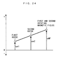
- the invention as claimed in claim 14 is the electric motor 1, 20, 30, 40, 60, 100 as claimed in any one of claims 1 to 12, further comprising a control device (ECU 17) for controlling the first and second moving magnetic fields such that speeds of the first moving magnetic field, the second member, and the third member (magnetic field rotational speed V0, magnetic field electrical angular velocity ⁇ MF, first shaft rotational speed V1, second shaft rotational speed V2, first rotor electrical angular velocity ⁇ e1, second rotor electrical angular velocity ⁇ e2) mutually satisfy a collinear relationship, and at the same time speeds of the second moving magnetic field, the fifth member, and the sixth member (magnetic field rotational speed V0, magnetic field electrical angular velocity ⁇ MF, first shaft rotational speed V1, second shaft rotational speed V2, first rotor electrical angular velocity ⁇ e1, second rotor electrical angular velocity ⁇ e2) mutually satisfy a collinear relationship.
- a control device ECU 17
- the control device controls the first and second moving magnetic fields such that the speeds of the first moving magnetic field, the second member, and the third member mutually satisfy a collinear relationship, and at the same time the speeds of the second moving magnetic field, the fifth member, and the sixth member mutually satisfy a collinear relationship.
- the members are driven by the magnetic forces caused by the first magnetic force lines between the first armature magnetic poles, the first soft magnetic material elements, and the first magnetic poles, and the magnetic forces caused by the second magnetic force lines between the second armature magnetic poles, the second soft magnetic material elements, and the second magnetic poles.
- the invention as claimed in claim 15 is the electric motor 1, 20, 30, 40, 60, 100 as claimed in any one of claims 1 to 12, wherein the first and fourth members are connected to each other, the electric motor further comprising a relative positional relationship-detecting device (first rotational position sensor 105, second rotational position sensor 106, ECU 17) for detecting one of a relative positional relationship between the first member, the second member, and the third member, and a relative positional relationship between the fourth member, the fifth member, and the sixth member, and a control device (ECU 17) for controlling the first and second moving magnetic fields based on the detected one of the relative positional relationships (first rotor electrical angle ⁇ e1, second rotor electrical angle ⁇ e2).
- a relative positional relationship-detecting device first rotational position sensor 105, second rotational position sensor 106, ECU 17
- ECU 17 for controlling the first and second moving magnetic fields based on the detected one of the relative positional relationships (first rotor electrical angle ⁇ e1, second rotor electrical angle ⁇ e2).
- the first member and the fourth member are connected to each other.
- the relative positional relationship-detecting device detects the relative positional relationship (hereinafter referred to as "the first relative positional relationship") between the three of the first to third members, or the relative positional relationship (hereinafter referred to as "the second relative positional relationship") between the three of the fourth to sixth members. Further, based on the detected first or second relative positional relationship, the control device controls the first and second moving magnetic fields.
- the members are connected as described above, it is possible to grasp, based on a detected one of the first relative positional relationship and the second relative positional relationship, the other of the relationships. Therefore, similarly to the case of claim 13, it is possible to ensure an appropriate operation of the electric motor. Further, since only one positional relationship-detecting device is used, compared with the case of claim 13 in which the first and second relative positional relationship-detecting device are used, it is possible to reduce the number of components, to thereby reduce the manufacturing costs and reduce the size of the electric motor.
- the invention as claimed in claim 16 is the electric motor 1, 20, 30, 40, 60, 100 as claimed in claim 15, wherein the relative positional relationship-detecting device detects, as the one of the relative positional relationships, electrical angular positions of the second and third members with respect to the first member, or electrical angular positions of the fifth and sixth members with respect to the fourth member, and wherein the control device controls the first and second moving magnetic fields based on the difference between a value of a two-fold of the detected electrical angular position (second rotor electrical angle ⁇ e2) of the third or sixth member, and the detected electrical angular position (first rotor electrical angle ⁇ e1) of the second or fifth member.
- the relative positional relationship-detecting device detects, as the one of the relative positional relationships, electrical angular positions of the second and third members with respect to the first member, or electrical angular positions of the fifth and sixth members with respect to the fourth member, and wherein the control device controls the first and second moving magnetic fields based on the difference between a value of a two-fold
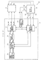
- an equivalent circuit corresponding to the first to third members is illustrated e.g. as in FIG. 25
- an equivalent circuit corresponding to the fourth to sixth members is illustrated e.g. as in FIG. 26 .
- Vu, Vv and Vw represent voltages of U-phase to W-phase coils, respectively, and Ru, Rv, and Rw are respective resistances of the U-phase to W-phase coils.
- Lu, Lv, and Lw represent respective self-inductances of the U-phase to W-phase coils.
- Muv represents a mutual inductance between the U-phase coil and the V-phase coil
- Mvw a mutual inductance between the V-phase coil and the W-phase coil
- Mwu a mutual inductance between the W-phase coil and the U-phase coil
- s a differential operator i.e. d/dt.
- Iu, Iv, and Iw represent electric currents flowing through the U-phase to W-phase coils, respectively.
- ⁇ FA represents a maximum value of the magnetic flux of the first magnetic pole passing through the coil of each phase via the first soft magnetic material element or a maximum value of the magnetic flux of the second magnetic pole passing through the coil of each phase via the second soft magnetic material element.
- ⁇ E1 represents the electrical angular position of the second member with respect to the first member, or the electrical angular position of the fifth member with respect to the fourth member
- ⁇ E2 represents the electrical angular position of the third member with respect to the first member, or the electrical angular position of the sixth member with respect to the fourth member (for convenience's sake, in FIGS.
- ⁇ E2 is illustrated as the electrical angular position of the third member). Further, ⁇ E1 represents a value obtained by differentiating ⁇ E1 with respect to time, i.e. an electrical angular velocity of the second member or the fifth member, wherein ⁇ E2 represents a value obtained by differentiating ⁇ E2 with respect to time, i.e. an electrical angular velocity of the third member or the sixth member.
- FIG. 27 shows an equivalent circuit of a general brushless DC motor of a one-rotor type.
- the voltage equation of the brushless DC motor is represented by the following equation (2):
- Vu Vv Vw Ru + s ⁇ Lu s ⁇ Muv s ⁇ Mwu s ⁇ Muv Rv + s ⁇ Lv s ⁇ Mvw s ⁇ Mwu s ⁇ Mvw Rw + s ⁇ Lw ]
- ⁇ f represents a maximum value of the magnetic flux of a magnetic pole of the rotor passing through the coil of each phase
- ⁇ e represents an electrical angular position of the rotor with respect to the stator.
- ⁇ e represents a value obtained by differentiating
- the voltage equation of the electric motor according to the present invention becomes identical to the voltage equation of the general brushless DC motor when (20E2 - ⁇ E1) is replaced by ⁇ e, and (2 ⁇ E2 - ⁇ E1) by ⁇ e. From this, it is understood that to operate the electric motor according to the invention, it is only required to control the respective electrical angular positions of vectors of the first and second moving magnetic fields with respect to the first and fourth members to electrical angular positions represented by (2 ⁇ E2 - ⁇ E1), i.e.
- the electrical angular positions of the second member and the third member with respect to the first member or the electrical angular positions of the fifth member and the sixth member with respect to the fourth member are detected. Further, based on the difference between the value of a two-fold of the electrical angular position of the third member and the electrical angular position of the second member, or the difference between the value of a two-fold of the electrical angular position of the sixth member and the electrical angular position of the fifth member, the first and second moving magnetic fields are controlled. Therefore, it is possible to ensure an appropriate operation of the electric motor under the aforementioned conditions (a) to (c).
- the present invention it is only required to empirically determine a map representing the relationship between one parameter concerning the rotational speed represented by the aforementioned difference of electrical angular positions, torque, and voltage, and control the first and second moving magnetic fields based on the map, and hence differently from the above-mentioned case, it is unnecessary to prepare maps for the first to sixth members, on a member-by-member basis, and it is very easy to perform the control. It is possible to reduce the memory of the control device and computation load.
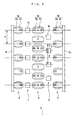
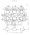
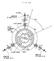
- FIG. 1 shows an electric motor 1 according to a first embodiment of the present invention.
- the electric motor 1 is comprised of a casing 2, a shaft 3, first to third stators 4 to 6 disposed within the casing 2, and first and second rotors 7 and 8.
- the second stator 5 is disposed in the center of the casing 2, and the first and second rotors 7 and 8 are disposed on respective opposite sides of the second stator 5 in a manner opposed thereto and spaced by a predetermined distance.
- the first and third stators 4 and 6 are disposed on respective outer sides of the first and second rotors 7 and 8 in a manner opposed thereto and spaced by a predetermined distance.
- the casing 2 has a hollow cylindrical peripheral wall 2a, and side walls 2b and 2c formed integrally therewith and arranged on opposite side ends thereof in a manner opposed to each other.
- the side walls 2b and 2c are annular plate-shaped members having holes 2d and 2e formed through the respective centers thereof, and the outer diameters thereof are equal to that of the peripheral wall 2a.
- the peripheral wall 2a and the side walls 2b and 2c are arranged concentrically with each other.
- bearings 9 and 10 are fitted in the above holes 2d and 2e, respectively.
- the shaft 3 is rotatably supported by the bearings 9 and 10. It should be noted that the shaft 3 is made substantially axially immovable by a thrust bearing (not shown).
- the first stator 4 has 2n first electromagnets 4a.
- Each first electromagnet 4a is comprised of a cylindrical iron core 4b which slightly extends in a direction of the axis of the shaft 3 "hereinafter referred to as "the axial direction"), and a coil 4c wound around the iron core 4b.
- the first electromagnet 4a is mounted on an end of the inner peripheral surface of the peripheral wall 2a toward the side wall 2b of the casing 2 via an annular fixing part 4d, and one end of the iron core 4b is mounted on the side wall 2b of the casing 2.
- the first electromagnets 4a are arranged side by side in a direction of the circumference of the shaft 3 (hereinafter referred to as "the circumferential direction”) at equally spaced intervals at a predetermined pitch P.
- each first electromagnet 4a is connected to a variable power supply 15.
- the variable power supply 15 is a combination of an electric circuit comprised of a converter, and a battery, and is connected to an ECU 17, referred to hereinafter.
- the first electromagnets 4a are configured such that each two iron cores 4b adjacent to each other generate respective magnetic poles different in polarity when electric power is supplied thereto from the variable power supply 15 (see FIG. 2 ).
- the magnetic pole of the first electromagnet 4a is referred to as "the first magnetic pole").
- the casing 2 corresponds to first, second, fourth, and fifth members, the shaft 3 to third and sixth members, the first stator 4 to a first magnetic pole row, the first electromagnets 4a to first magnetic poles, the ECU 17 to magnetic force adjustment means, a first relative positional relationship-detecting device, and a second relative positional relationship-detecting device.
- the second stator 5 generates a rotating magnetic field according to the supply of electric power, and has 3n armatures 5a.
- Each armature 5a is comprised of a cylindrical iron core 5b slightly extending in the axial direction, a coil 5c wound around the iron core 5b by concentrated winding, and so forth.
- the 3n coils 5c form n sets of three-phase coils of U-phase coils, V-phase coils, and W-phase coils.
- the armatures 5a are mounted on a central portion of the inner peripheral surface of the peripheral wall 2a via an annular fixing portion 5d such that they are arranged at equally spaced intervals in the circumferential direction.
- the armatures 5a and the first electromagnets 4a are arranged such that the center of every third armature 5a and the center of every second first electromagnet 4a which have the same polarity is circumferentially in the same position.
- the center of each armature 5a having the U-phase coil 5c is at the same circumferential position as that of each first electromagnet 4a having an N pole (see FIG. 2 ).
- each armature 5a is connected to a variable power supply 16.
- the variable power supply 16 is a combination of an electric circuit comprised of an inverter, and a battery, and is connected to the ECU 17.
- the armatures 5a are configured to generate different magnetic poles at ends of each iron core 5b on respective sides toward the first stator 4 and the third stator 6, when electric power is supplied from the variable power supply 16, and along with generation of these magnetic poles, the first and second rotating magnetic fields are generated between the first stator 4 and the second stator 5 and between the third stator 6 and the second stator 5, respectively, such that they rotate in the circumferential direction.
- the magnetic poles generated on the ends of the iron core 5b on respective sides toward the fist and third stators 4 and 6 are referred to as “the first armature magnetic pole” and “the second armature magnetic pole”. Further, the numbers of the first and second armature magnetic poles are each equal to the number of magnetic poles of the first electromagnets 4a, i.e. 2n.
- the third stator 6 has second electromagnets 6a the number of which is equal to the number of first electromagnets 4a, i.e. 2n.
- Each second electromagnet 6a is comprised of a cylindrical iron core 6b which slightly extends in the axial direction, and a coil 6c wound around the iron core 6b. Further, the second electromagnet 6a is mounted on an end of the inner wall of the peripheral wall 2a toward the side wall 2c of the casing 2 via an annular fixing part 6d, and one end of the iron core 6b is mounted on the side wall 2c of the casing 2.
- the second electromagnets 6a are arranged side by side in the circumferential direction at equally spaced intervals, and such that the center of each thereof is at the same circumferential location as the center of each first electromagnet 4a and that of each armature 5a having the U-phase coil 5c (see FIG. 2 ).
- the second electromagnets 6a are connected to the power supply 15. Further, the second electromagnets 6a are configured such that when electric power is supplied form the variable power supply 15, the respective magnetic poles of each two second electromagnets 6a adjacent to each other are different in polarity, and at the same time the magnetic pole of each second electromagnet 6a has the same polarity as that of the first magnetic pole of each first electromagnet 4a at the same circumferential location (see FIG. 2 ).
- the magnetic pole of the second electromagnet 6a is referred to as "the second magnetic pole").
- the second stator 5 corresponds to first and second armature rows, the armatures 5a to first and second armatures, the coils 5c to three-phase field windings, the third stator 6 to the second magnetic pole row, and the second electromagnets 6a to the second magnetic poles.
- the first rotor 7 has first cores 7a the number of which is equal to the number of the first electromagnets 4a, i.e. 2n.
- Each first core 7a has a cylindrical shape formed by laminating soft magnetic material parts, e.g. a plurality of steel sheets, and slightly extends in the axial direction.
- the first core 7a is mounted on an outer end of a disc-shaped flange 7b provided integrally and concentrically with the shaft 3, and is rotatable in unison with the shaft 3. Further, the first cores 7a are arranged side by side in the circumferential direction at equally spaced intervals.
- the second rotor 8 has second cores 8a the number of which is equal to the number of the first electromagnets 4a, i.e. 2n.
- Each second core 8a has, similarly to the first core 7a, a cylindrical shape formed by laminating soft magnetic material parts, e.g. a plurality of steel sheets, and extends in the axial direction.
- the second core 8a is mounted on an outer end of a disc-shaped flange 8b provided integrally and concentrically with the shaft 3, and is rotatable in unison with the shaft 3. Furthermore, the second cores 8a are alternately arranged with respect to the first cores 7a, and the center of each second core 8a is displaced from the center of each first core 7a by a half P/2 of the predetermined pitch P.
- first and second rotors 7 and 8 correspond to first and second soft magnetic material rows, respectively, and the first and second cores 7a and 8a correspond to first and second soft magnetic elements.
- the electric motor 1 is provided with a rotational position sensor 50 (first positional relationship-detecting device, second positional relationship-detecting device) which delivers a signal indicative of a rotational position of the shaft 3 (hereinafter referred to as "the shaft rotational position") to the ECU 17.
- a rotational position sensor 50 first positional relationship-detecting device, second positional relationship-detecting device
- the ECU 17 controls the electric motor 1.
- the ECU 17 is implemented by a microcomputer including an I/O interface, a CPU, a RAM, and a ROM. Further, the ECU 17 determines the relative positional relationship between the armatures 5a, the first and second electromagnets 4a and 6a, and the first and second cores 7a and 8a, according to the input shaft rotational position, and controls energization of the three-phase coils 5c of the armatures 5a based on the positional relationship to thereby control the first and second rotating magnetic fields. Further, the ECU 17 calculates a rotational speed of the shaft 3 (hereinafter referred to as "the shaft rotational speed”) based on the shaft rotational position.
- the shaft rotational speed a rotational speed of the shaft 3
- the ECU 17 calculates load on the electric motor 1 based on the shaft rotational speed, the electric power supplied to the armatures 5a and the first and second electromagnets 4a and 6a, and controls the electric current supplied to the armatures 5a, and the first and second electromagnets 4a and 6a according to the calculated load.
- This controls the magnetic forces of the magnetic poles of the first and second armature magnetic poles and the first and second magnetic poles, and the rotational speed of the first and second rotating magnetic fields.
- the magnetic forces of the first and second armature magnetic poles and the magnetic forces of the first and second magnetic poles are made stronger as the calculated load is higher.
- the magnetic forces of the first and second armature magnetic poles and those of the first and second magnetic poles are made weaker.
- each first armature magnetic pole when the polarity of each first armature magnetic pole is different from the polarity of an opposed (closest) one of the first magnetic poles, the polarity of each second armature magnetic pole is the same as the polarity of an opposed (closest) one of the second magnetic poles.
- each first core 7a is in a position between each first magnetic pole and each first armature magnetic pole
- each second core 8a is in a position between a pair of second armature magnetic poles circumferentially adjacent to each other and a pair of second magnetic poles circumferentially adjacent to each other.
- each second armature magnetic pole when the polarity of each second armature magnetic pole is different from the polarity of an opposed (closest) one of the second magnetic poles, the polarity of each first armature magnetic pole is the same as the polarity of an opposed (closest) one of the first magnetic poles.
- each first core 7a when each second core 8a is in a position between each second magnetic pole and each second armature magnetic pole, each first core 7a is in a position between a pair of first armature magnetic poles circumferentially adjacent to each other, and a pair of first magnetic poles circumferentially adjacent to each other.
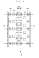
- the shaft 3, and the flanges 7a and 8a are omitted from illustration, for convenience.
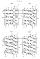
- the operation of the electric motor 1 is described by replacing the motions of the first and second rotating magnetic fields by an equivalent physical motion of 2n imaginary permanent magnets (hereinafter referred to as "the imaginary magnets") 18, equal in number to the respective numbers of the first and second electromagnets 4a and 6a.
- the imaginary magnets 2n imaginary permanent magnets
- each imaginary magnet 18 on respective sides toward the first stator 4 and the third stator 6 as the first and second armature magnetic poles, respectively, and rotating magnetic fields generated between the first stator 4 and the imaginary magnets 18 and between the third stator 6 and the imaginary magnets 18 as the first and second rotating magnetic fields, respectively.
- the first and second rotating magnetic fields are generated in a manner rotated downward, as viewed in the figure, from a state in which each first core 7a is opposed to each first electromagnet 4a, and each second core 8a is in a position between each adjacent two of the second electromagnets 6a.
- the polarity of each first armature magnetic pole is made different from the polarity of each opposed one of the first magnetic poles, and the polarity of each second armature magnetic pole is made the same as the polarity of each opposed one of the second magnetic poles.
- first magnetic force lines G1 magnetic lines G1 of force (hereinafter referred to as “the first magnetic force lines G1") are generated between the first magnetic poles, the first cores 7a, and the first armature magnetic poles.
- second cores 8a are disposed between the second and third stators 5 and 6, they are magnetized by the second armature magnetic poles and the second magnetic poles, and magnetic lines G2 of force (hereinafter referred to as “the second magnetic force lines G2”) are generated between the first armature magnetic poles, the second cores 8a, and the second magnetic poles.
- the first magnetic force lines G1 are generated such that they each connect the first magnetic pole, the first core 7a, and the first armature magnetic pole
- the second magnetic force lines G2 are generated such that they connect each circumferentially adjacent two second armature magnetic poles and the second core 8a located therebetween, and connect each circumferentially adjacent two second magnetic poles and the second core 8a located therebetween.
- magnetic circuits as shown in FIG. 6(a) are formed.
- the first magnetic force lines G1 are linear, no magnetic forces for circumferentially rotating the first cores 7a act on the first cores 7a.
- the two second magnetic force lines G2 between each circumferentially adjacent two second armature magnetic poles and the second core 8a are equal to each other in the degree of bend thereof and in the total magnetic flux amount.
- the two second magnetic force lines G2 between each circumferentially adjacent two second magnetic poles and the second core 8a are equal to each other in the degree of bend thereof and in the total magnetic flux amount.
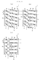
- the second magnetic force lines G2 are generated such that they each connect between a second armature magnetic pole, a second core 8a, and a second magnetic pole, and respective portions of the first magnetic force lines G1 between the first cores 7a and the first armature magnetic poles are bent. Further, accordingly, magnetic circuits are formed by the first magnetic force lines and the second magnetic force lines, as shown in FIG. 6(b) .
- each first magnetic force line G1 since the degree of bend of each first magnetic force line G1 is small but the total magnetic flux amount thereof is large, a relatively large magnetic force acts on the first core 7a.
- the degree of bend of the second magnetic force line G2 is large, the total magnetic flux amount thereof is small, so that a relatively small magnetic force acts on the second core 8a.
- the first and second cores 7a and 8a are driven in the magnetic field rotation direction by magnetic forces caused by the first and second magnetic force lines G1 and G2, so that the shaft 3 rotates in the magnetic field rotation direction.
- the first magnetic force lines G1 increase in the degree of bend thereof but decrease in the total magnetic flux amount thereof, whereby the magnetic forces acting on the first cores 7a progressively decrease to progressively reduce the driving forces for driving the first cores 7a in the magnetic field rotation direction.
- the second magnetic force lines G2 decrease in the degree of bend thereof but increase in the total magnetic flux amount thereof, whereby the magnetic forces acting on the second cores 8a progressively increase to progressively increase the driving forces for driving the second cores 8a in the magnetic field rotation direction.
- the shaft 3 rotates in the magnetic field rotation direction, while the driving forces acting on the respective first and second cores 7a and 8a repeatedly increase and decrease by turns in accordance with the rotations of the imaginary magnets 18, that is, the rotations of the first and second rotating magnetic fields.
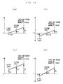
- the relationship between the driving forces TRQ7a and TRQ8a acting on the respective first and second cores 7a and 8a (hereinafter referred to as “the first driving force” and “the second driving force”, respectively), and the torque TRQ3 of the shaft 3 (hereinafter referred to as “the shaft torque TRQ3”) is as shown in FIG. 7 .
- the first and second driving forces TRQ7a and TRQ8a change approximately sinusoidally at the same repetition period, and phases thereof are displaced from each other by a half period. Further, since the shaft 3 has the first and second core 7a and 8a connected thereto, the shaft torque TRQ3 is equal to the sum of the first and second driving forces TRQ7a and TRQ8a that change as described above, and becomes approximately constant.
- the first and second cores 7a and 8a are rotated by the magnetic forces caused by the first and second magnetic force lines G1 and G2, and therefore the first and second cores 7a and 8a are rotated in a state slightly delayed relative to the first and second rotating magnetic fields. Therefore, during the rotations of the first and second rotating magnetic fields, when the imaginary magnets 18 are in a position shown in FIG. 5(c) , the first and second cores 7a and 8a are actually in a position slightly shifted in a direction (upward, as viewed in the figure) opposite to the magnetic field rotation direction with respect to the position shown in FIG. 5(c) . For ease of understanding of the aforementioned rotational speed, however, the first and second cores 7a and 8a are presented in the respective positions in the figure.
- the magnetized states of the first and second cores 7a and 8a vary, which makes it possible to cause the shaft 3 to rotate without slippage, and the electric motor 1 functions as a synchronous motor differently from the conventional electric motor described hereinbefore, which makes it possible to increase the efficiency thereof.
- the respective numbers of the first armature magnetic poles, the first magnetic poles, and the first cores 7a are set to be equal to each other, it is possible to generate the first magnetic force lines G1 properly in all the first armature magnetic poles, the first magnetic poles, and the first cores 7a.
- the respective numbers of the second armature magnetic poles, the second magnetic poles, and the second core 8a are set to be equal to each other, it is possible to properly generate the second magnetic force lines G2 in all the second armature magnetic poles, the second magnetic poles, and the second cores 8a. From the above, it is possible to sufficiently obtain the torque of the electric motor 1.
- the electric motor 1 can be downsized by the size of eliminated slip rings, and the efficiency thereof can be further enhanced since no heat is generated due to friction resistance of the slip rings and associated brushes.
- first and second cores 7a and 8a formed by laminates of steel sheets are rotated, it is possible to further improve durability of the electric motor compared with the case where the permanent magnets lower in strength are rotated.
- first and second electromagnets 4a and 6a are used, differently from the use of permanent magnets which are large in magnetic force, it is possible to carry out the operations of assembling the electric motor 1 without performing the aforementioned operations for preventing contact between components. Further, in driving the shaft 3 by inputting power to the armatures 5a without supplying electric power thereto, differently from the case where permanent magnets are used for the first and second electromagnets 4a and 6a, it is possible to prevent occurrence of loss due to the magnetic forces thereof, by stopping energization thereof.
- the ECU 17 increases the magnetic forces of the first and second electromagnets 4a and 6a as the load on the electric motor 1 is higher. Therefore, when a large output is required due to high load, it is possible to increase the magnetic forces of the first and second electromagnets 4a and 6a, and hence increase the magnetic forces caused by the aforementioned first and second magnetic force lines G1 and G2, which makes it possible to obtain a sufficient output. Further, when a large output is not required due to low load, it is possible to reduce the magnetic forces of the first and second electromagnets 4a and 6a, and hence reduce the induced electromotive force of the armatures 5a, which makes it possible to enhance the efficiency.
- the magnetic forces of the first and second armature magnetic poles and the first and second magnetic poles are made weaker, and hence it is possible to reduce field-reducing current supplied to the armatures 5a during high speed rotation, which makes it possible to enhance the efficiency.
- the stator for generating the first and second rotating magnetic fields is formed by the single second stator 5, and the first to third stators 4 to 6 are mounted on the single peripheral wall 2a. Further, the first and second rotors 7 and 8 are mounted on the single shaft 3.
- the stator for generating the first and second rotating magnetic fields is formed by two stators, and the first to third stators 4 to 6 and the first and second rotors 7 and 8 are mounted on respective different members, the number of component parts can be reduced, whereby it is possible to reduce the manufacturing costs and achieve downsizing.
- first to third stators 4 to 6 and the first and second rotors 7 and 8 are arranged side by side in the axial direction, it is possible to reduce the diametrical size of the electric motor 1.
- control of the first and second rotating magnetic fields is performed based on the relative positional relationship between the armatures 5a and the first and second electromagnets 4a and 6a, and the first and second cores 7a and 8a
- control may be performed based on the relative positional relationship between arbitrary portions of the casing 2 or the first to third stators 4 to 6, and arbitrary portions of the shaft 3 or the first and second rotors 7 and 8.
- FIG. 9 shows a first variation of the first embodiment.
- the first and second electromagnets 4e and 6e have permanent magnets 4f and 6f which can magnetize the iron cores 4b and 6b.
- These permanent magnets 4f and 6f have respective end faces thereof secured to the iron cores 4b and 6b, and respective opposite ends thereof opposed to the first and second rotors 7 and 8.
- ones of the permanent magnets 4f and 6f at the circumferentially same locations are the same in polarity, while ones of the same at circumferentially adjacent locations are different from each other in polarity. Therefore, it is possible to obtain the same advantageous effects as provided by the first embodiment.
- the first and second electromagnets 4e and 6e correspond to the first and second magnetic poles, respectively.
- FIG. 10 show a second variation of the first embodiment.
- first and second permanent magnets 4g and 6g are provided in place of the first and second electromagnets 4a and 6a. Since the first and second permanent magnets 4g and 6g are disposed in the same manner as the first and second electromagnets 4a and 6a, it is possible to obtain the same advantageous effects as the first embodiment. Further, differently from the first embodiment or the first variation, the variable power supply 15 and the coils 4c can be dispensed with. This makes it possible to reduce the size of the electric motor 1, and simplify the construction thereof. It should be noted that the first and second permanent electromagnets 4g and 6g correspond to the first and second magnetic poles, respectively.
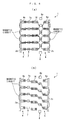
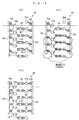
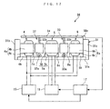
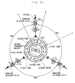
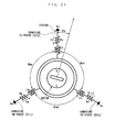
- an electric motor 20 according to a second embodiment of the present invention will be described with reference to FIG. 11 .
- the electric motor 20 according to the present embodiment is of a type in which the stator and the like are radially arranged.
- component parts of the electric motor 20 which are identical to those of the first embodiment described above are denoted by the same reference numerals.
- a description will be mainly given of different points from the first embodiment.
- the electric motor 20 is comprised of a first shaft 21 and a second shaft 22 which are rotatably supported on the bearings 9 and 10, respectively, a first rotor 23 accommodated within the casing 2, a stator 24 disposed within the casing 2 in a manner opposed to the first rotor 23, and a second rotor 25 disposed between the two rotors 23 and 24, in a manner spaced from each by a predetermined distance.
- the first rotor 23, the second rotor 25, and the stator 24 are disposed in the direction of radius of the first shaft 21 from inside in the mentioned order.
- the first and second shafts 21 and 22 are arranged concentrically and are made substantially immovable in the axial direction by a thrust bearing (not shown).
- the first rotor 23 has 2n first permanent magnets 23a and second permanent magnets 23b.
- the first and second permanent magnets 23a and 23b are arranged at equally spaced intervals in the circumferential direction of the first shaft 21 (hereinafter simply referred to as "the circumferential direction"), respectively.
- Each first permanent magnet 23a has a sector-shaped cross-section orthogonal to the axial direction of the first shaft 21 (hereinafter simply referred to as "the axial direction”), and slightly extends in the axial direction.
- Each second permanent magnet 23b has the same shape and size as the shape and size of the first permanent magnet 23a.
- first and second permanent magnets 23a and 23b are mounted on the outer peripheral surface of an annular fixing portion 23c, in a state arranged axially, i.e. in the axial direction, side by side, and in contact with each other.
- the above-mentioned fixing portion 23c is formed of a soft magnetic material element, such as iron, and has an inner peripheral surface thereof attached to the outer peripheral surface of a disk-shaped flange 23d integrally concentrically formed with the first shaft 21.
- the first and second permanent magnets 23a and 23b are rotatable in unison with the first shaft 21.
- a central angle formed by each two first and second permanent magnets 23a and 23b adjacent to each other circumferentially, i.e. in the circumferential direction, about the first shaft 21 is a predetermined angle ⁇ .
- ones of the first and second permanent magnets 23a and 23b positioned side by side in the axial direction are the same in polarity, while ones of the same circumferentially adjacent to each other are different from each other in polarity.
- respective magnetic poles of the first and second permanent magnets 23a and 23b are referred to as "the first magnetic pole" and "the second magnetic pole", respectively.
- the casing 2 corresponds to the first and fourth members, the first shaft 21 to the second and fifth members, the second shaft 22 to the third and sixth members, the first rotor 23 to the first and second magnetic pole rows, and the first and second permanent magnets 23a and 23b to the first and second magnetic poles.
- each armature 24a is comprised of an iron core 24b, and a coil 24c wound around the iron core 24b by concentrated winding.
- the iron core 24b has a generally sector-shaped cross-section orthogonal to the axial direction, and has an axial length approximately twice as long as that of the first permanent magnet 23a.
- An axially central portion of the inner peripheral surface of the iron core 24b is formed with a circumferentially extending groove 24d.
- the 3n coils 24c form n sets of three-phase (U-phase, V-phase, and W-phase) coils (see FIG. 12 ).
- the armatures 24a are mounted on the inner peripheral surface of the peripheral wall 2a via an annular fixing portion 24e. Due to the numbers and the arrangements of the armatures 24a and the first and second permanent magnets 23a and 23b, when the center of a certain armature 24a circumferentially coincides with the center of certain first and second permanent magnets 23a and 23b, the center of every third armature 24a from the armature 24a, and the center of every second first and second permanent magnets 23a and 23b from the respective first and second permanent magnets 23a and 23b circumferentially coincide with each other.
- each armature 24a is connected to the variable power supply 16, and is configured such that when electric power is supplied, magnetic poles having different polarities from each other are generated on respective end portions of the iron core 24b toward the first and second permanent magnets 23a and 23b. Further, in accordance with generation of these magnetic poles, first and second rotating magnetic fields are generated between the first permanent magnets 23a of the first rotor 23 and the end portion of the iron core 24b, and between the second permanent magnets 23b of the first rotor 23 and the end portion of the iron core 24b, in a circumferentially rotating manner, respectively.
- the magnetic poles generated on the respective end portions of the iron core 24b toward the first and second permanent magnets 23a and 23b are referred to as “the first armature magnetic pole” and “the second armature magnetic pole”, respectively.
- the number of the first armature magnetic poles and that of the second armature magnetic poles are equal to the number of the magnetic poles of the first permanent magnet 23a, that is, 2n.
- stator 24 corresponds to first and second armature rows, the armatures 24a to the first and second armatures, and the coils 24c to the three-phase field windings, respectively.
- the second rotor 25 has a plurality of first cores 25a and a plurality of second cores 25b.
- the first and second cores 25a and 25b are arranged at equally spaced intervals in the circumferential direction, respectively, and the numbers of 25a and 25b are both set to be equal to that of the first permanent magnet 23a, that is, 2n.
- Each first core 25a is formed by laminating soft magnetic material parts, e.g. a plurality of steel sheets, such that it has a sector-shaped cross-section orthogonal to the axial direction, and axially extends by a predetermined length.
- each second core 25b is formed by laminating a plurality of steel plates, such that it has a sector-shaped cross-section orthogonal to the axial direction, and axially extends by a predetermined length.
- the first and second cores 25a and 25b are mounted on an outer end of a disk-shaped flange 25e via bar-shaped connecting portions 25c and 25d slightly extending in the axial direction, respectively.
- the flange 25e is integrally concentrically provided on the second shaft 22. With this arrangement, the first and second cores 25a and 25b are rotatable in unison with the second shaft 22.
- first cores 25a are each axially arranged between the first permanent magnet 23a of the first rotor 23 and the stator 24, and the second cores 25b are each axially arranged between the second permanent magnet 23b of first rotor 23 and the stator 24. Furthermore, the second cores 25b are circumferentially alternately arranged with respect to the first cores 25a, and the center of the second core 25b is displaced by half of the predetermined angle ⁇ from the center of the first core 25a.
- the second rotor 25 corresponds to the first and second soft magnetic material element rows, the first cores 25a to the first soft magnetic substance elements, and the second cores 25b to the second soft magnetic material elements, respectively.
- the electric motor 20 is provided with first and second rotational angle sensors 50a and 50b (the first relative positional relationship-detecting device and the second relative positional relationship-detecting device).
- the rotational angle sensors 50a and 50b detect respective rotational angular positions of the first and second shafts 21 and 22, and deliver respective signals indicative of the sensed rotational angular positions to the ECU 17.
- the ECU 17 determines, based on the detected rotational positions of the first and second shafts 21 and 22, the relative positional relationship between the armatures 24a, the first and second permanent magnets 23a and 23b, and the first and second cores 25a and 25b, and controls, based on the positional relationship, the energization of the three-phase coils 5c of the armatures 5a, to thereby control the first and second rotating magnetic fields.
- the electric motor 20 constructed as above is configured such that in a state in which one of the first and second shaft 21 and 22 is fixed, or power is input thereto, the other of the same is caused to rotate.
- each first armature magnetic pole when the polarity of each first armature magnetic pole is different from the polarity of an opposed (closest) one of the first magnetic poles, the polarity of each second armature magnetic pole becomes the same as the polarity of an opposed (closest) one of the second magnetic poles.
- each first core 25a is in a position between a first magnetic pole and a first armature magnetic pole
- each second core 25b is in a position between a pair of second armature magnetic poles circumferentially adjacent to each other and a pair of second magnetic poles circumferentially adjacent to each other.
- each second armature magnetic pole when the polarity of each second armature magnetic pole is different from the polarity of an opposed (closest) one of the second magnetic poles, the polarity of each first armature magnetic pole becomes the same as the polarity of an opposed (closest) one of the first magnetic poles.
- each first core 25a when each second core 25b is in a position between a second magnetic pole and a second armature magnetic pole, each first core 25a is in a position between a pair of first armature magnetic poles circumferentially adjacent to each other, and a pair of first magnetic poles circumferentially adjacent to each other.
- FIG. 12 the armatures 24a and the fixing portions 24e are shown as if they were each divided into two parts since FIG. 12 is shown as a development view, actually, they are a one-piece member, so that the arrangement in FIG. 12 can be shown as in FIG. 13 as equivalent thereto. It is apparent from comparison between FIG. 13 and FIG. 2 referred to hereinabove that the positional relationship between the first and second permanent magnets 23a and 23b, the armatures 24a, and the fist and second cores 25a and 25b is the same as that between the first and second electromagnets 4a and 6a, the armatures 5a, and the first and second cores 7a and 8a, described hereinabove.
- the following description of the operation of the electric motor 20 will be given assuming that the first and second permanent magnets 23a and 23b, the armatures 24a, and the first and second cores 25a and 25b are arranged as shown in FIG. 13 . Further, the description of the operation of the electric motor 20 is given similarly to that of the electric motor 1 given above, by replacing the motions of the first and second rotating magnetic fields by the physical motions of the imaginary magnets 18.
- the operation of the electric motor 20 for causing the second shaft 22 to rotate with the first shaft 21 being fixed is the same as the operation of the electric motor 1 described hereinbefore with reference to FIGS. 4 and 5 , and hence description thereof is omitted.
- the relationship between the rotational speed of the first shaft 21 (hereinafter referred to as "the first shaft rotational speed”) V1, the second shaft rotational speed V2, and the magnetic field rotational speed V0 is represented as shown in FIG. 14(a) .
- first cores 25a are disposed as described above, they are magnetized by the first magnetic poles and the first armature magnetic poles, and magnetic lines of force (hereinafter referred to as “the first magnetic force lines”) G1' are generated between the first magnetic poles, the first cores 25a, and the first armature magnetic poles.
- second cores 25b are disposed as described above, they are magnetized by the second armature magnetic poles and the second magnetic poles, and magnetic lines of force (hereinafter referred to as "the second magnetic force lines”) G2'are generated between the second armature magnetic poles, the second cores 25b, and the second magnetic poles.
- the first and second rotating magnetic fields are generated in a manner rotated downward, as viewed in the figure, from a state in which each first core 25a is opposed to each first permanent magnet 23a, and each second core 25a is in a position between each adjacent two of the second permanent magnets 23b.
- the polarity of each first armature magnetic pole is made different from the polarity of an opposed one of the first magnetic poles, and the polarity of each second armature magnetic pole is made the same as the polarity of an opposed one of the second magnetic poles.
- the first magnetic force line G1' between the first magnetic pole and the first core 25a is large, the first magnetic force line G1' is straight, and hence no magnetic forces are generated which cause the first permanent magnet 23a to rotate with respect to the first core 25a.
- the distance from the second magnetic pole to the second armature magnetic pole having a different polarity than that is relatively large, the total magnetic flux amount of the second magnetic force line G2' between the second core 25b and the second magnetic pole is relatively small.
- the degree of bend of the second magnetic force lines G2 is large, magnetic forces act on the second permanent magnet 23b, so as to make the second permanent magnet 23b closer to the second core 25b.
- the imaginary magnets 18 rotate toward a position shown in FIG. 15(d) .
- the second permanent magnets 23b become closer to the second cores 25b to make the degree of bend of the second magnetic force lines G2' between the second cores 25b and the second magnetic poles smaller, the imaginary magnets 18 become further closer to the second cores 25b, which increases the total magnetic flux amounts of the second magnetic force lines G2'.
- the magnetic forces act on the second permanent magnets 23b so as to make the second permanent magnets 23b closer to the second cores 25b, whereby the second permanent magnets 23b are driven, together with the first permanent magnets 23a, in the direction opposite to the magnetic field rotation direction.
- the first magnetic force lines G1' between the first magnetic poles and the first cores 25a are bent, whereby magnetic forces act on the first permanent magnet 23a so as to make the first permanent magnet 23a closer to the first cores 25a.
- a magnetic force caused by the first magnetic force line G1' is smaller than the aforementioned magnetic force caused by the second magnetic force line G2', since the degree of bend of the first magnetic force line G1' is smaller than that of the second magnetic force line G2'.
- a magnetic force corresponding to the difference between the two magnetic forces drives the second permanent magnet 23b, together with the first permanent magnet 23a, in the direction opposite to the magnetic field rotation direction.
- the first permanent magnets 23a are driven, together with the second permanent magnets 23b, in the direction opposite to the magnetic field rotation direction, by respective magnetic forces corresponding to the differences between the magnetic forces caused by the first magnetic force lines G1' between the first magnetic poles and the first cores 25a, and the magnetic forces caused by the second magnetic force lines G2' between the second cores 25b and the second magnetic poles.
- the first permanent magnets 23a are driven, together with the second permanent magnets 23b, by the magnetic forces caused by the first magnetic force lines G1'.
- the magnetic forces caused by the first magnetic force lines G1' between the first magnetic poles and the first cores 25a, the magnetic forces caused by the second magnetic force lines G2' between the second cores 25b and the second magnetic poles, and the magnetic forces corresponding to the differences between these magnetic forces alternately act on the first and second permanent magnets 23a and 23b, i.e. on the first shaft 21, whereby the first shaft 21 is rotated in the direction opposite to the magnetic field rotation direction.
- the magnetic forces, that is, the driving forces thus act on the first shaft 21 alternately, whereby the torque of the first shaft 21 is made approximately constant.
- the magnetic forces caused by the first and second magnetic force lines G1' and G2' act to cause the first and second permanent magnets 23a and 23b to rotate while the first and second cores 25a and 25b maintain the respective states positioned at a mid point between the first magnetic pole and the first armature magnetic pole and a mid point between the second magnetic pole and the second armature magnetic pole.
- the magnetic field rotational speed V0, the first shaft rotational speed V1, and the second shaft rotational speed V2 satisfy the following relationship:
- the first and second cores 7a and 8a rotate, while maintaining the respective states positioned at a mid point between the first magnetic poles and the first armature magnetic poles and at a mid point between the second magnetic poles and the second armature magnetic poles. This also applies to the first and second cores 25a and 25b, similarly.
- the rotational angle of the second shaft 22 integral with the both 25a and 25b is an average value of the rotational angle of the first and second rotating magnetic fields, and the rotational angle of the first and second magnetic poles, i.e. the rotational angle of the first shaft 21.
- FIG. 14(c) shows an example of the case in which both of the first and second shafts 21 and 22 are rotated in the field rotating direction
- FIG. 14(d) shows an example of the case in which the first shaft 21 is rotated in the opposite direction.
- the magnetized states of the first and second cores 25a and 25b vary depending on the relative rotational position of the first and second shafts 21 and 22, and hence the electric motor 20 can be caused to rotate without slippage, and functions as a synchronous motor, which makes it possible to enhance the efficiency thereof.
- the numbers of the first armature magnetic poles, the first magnetic poles, and the first cores 25a are set to be equal to each other, and the numbers of the second armature magnetic poles, the second magnetic poles, and the second cores 25b are set to be equal to each other, it is possible to sufficiently obtain torque of the electric motor 20 even when driving either of the first and second shafts 21 and 22.
- the armatures 24a are fixed to the casing 2, differently from the case where the armatures 24a are configured to be rotatable, a slip ring for supplying electric power to the armatures 24a can be dispensed with. Therefore, the electric motor 20 can be reduced in size accordingly, and no heat is generated by contact resistance between the slip ring and a brush, which makes it possible to further increase the efficiency thereof.
- the variable power supply 15 can be dispensed with, and it is possible to simplify the construction of the electric motor 20 and further reduce the size of the same.
- the slip ring for supplying electric power to the electromagnets can be dispensed with, and it is possible to downsize the electric motor 20 by the size of eliminated slip ring, and further increase the efficiency thereof.
- the general three-phase (U-phase, V-phase, and W-phase) coils 24c are used, similarly to the first embodiment, it is possible to construct the electric motor 20 easily and inexpensively without preparing special field windings.
- the stators for generating the first and second rotating magnetic fields are formed by the single stator 24, the first and second permanent magnets 23a and 23b are mounted on the single first shaft 21, and the first and second cores 25a and 25b are mounted on the single second shaft 22.
- the stators generating the fist and second rotating magnetic fields are formed by two stators, and the first and second permanent magnets 23a and 23b, and the first and second cores 25a and 25b are mounted on different members, it is possible to reduce the number of component parts similarly to the first embodiment, whereby it is possible to reduce the manufacturing costs and the size of the electric motor 20.
- the relative positional relationship between the armature 24a, the first and second electromagnets 23a and 23b, and the first and second cores 25a and 25b is determined, and based on the positional relationship, the first and second rotating magnetic fields are controlled. Further, as is apparent from FIG. 14 , the magnetic field rotational speed V0 is controlled such that a collinear relationship is satisfied between the same, and the fist and second shaft rotational speeds V1 and V2. This ensures an appropriate operation of the electric motor 20.
- stator 24 the first and second rotors 23 and 25 are arranged side by side in the radial or diametrical direction, it is possible to reduce the axial size of the electric motor 20.
- the first and second electromagnets 4a and 6a or 4e or 6e may be used.
- the electric motor 20 may be configured such that the stator 24 is rotatable, and while power is input to the stator 24 and one of the first and second rotors 23 and 25, the other of the two 23 and 25 may be caused to rotate.
- the electric motor 20 functions as a synchronous motor, which make it possible to enhance the efficiency thereof.
- control of the first and second rotating magnetic fields is performed based on the relative positional relationship between the armatures 24a, the first and second electromagnets 23a and 23b, and the first and second cores 25a and 25b
- control may be performed based on the relative positional relationship between arbitrary portions of the casing 2 or the stator 24, arbitrary portions of the first shaft 21 or the first rotor 23, and arbitrary portions of the second shaft 22 or the second rotor 25.
- an electric motor 30 according to a third embodiment of the present invention will be described with reference to FIGS. 17 and 18 .
- the electric motor 30 is configured as a linear motor.
- component parts of the electric motor 30 similar to those of the electric motor 1 according to the first embodiment described above are denoted by the same reference numerals.
- a description will be given mainly of points different from the first embodiment.
- the casing 31 of the electric motor 30 includes a plate-like bottom wall 31a the longitudinal direction of which is a front-rear direction (a side remote from the viewer and a side toward the viewer as viewed in FIG. 17 are a front side and a rear side, respectively), and side walls 31b and 31c integrally formed therewith which extend upward from opposite left and right ends of the bottom wall 31a, and are opposed to each other.
- the armatures 5a, the first and second electromagnets 4a and 6a are arranged in the longitudinal direction, and in this point alone, the third embodiment is different from the first embodiment, but the numbers, pitch, and arrangement of these are the same as the first embodiment.
- the first and second electromagnets 4a and 6a are mounted on a left end and a right end of the upper surface of the bottom wall 31a via fixing portions 4h and 6h, respectively. Further, the iron cores 4b and 6b of the both 4a and 6a are mounted on the inner surface of the side walls 31b and 31c, respectively.
- the armatures 5a are mounted on a central portion of the upper surface of the bottom wall 31a via a fixing portion 5e. Further, when electric power is supplied to the armatures 5a, the first and second moving magnetic fields are generated between the armatures 5a and the first stator 4 and between the armatures 5a and the third stator 6 in a manner moving in the front-rear direction.
- the electric motor 30 includes first and second moving elements 32 and 33 in place of the first and second rotors 7 and 8.
- the first and second moving elements 32 and 33 include respective pluralities of e.g. three first and second cores 7a and 8a arranged in the front-rear direction.
- the first and second cores 7a and 8a are alternately arranged in the front-rear direction at the same pitch as the first electromagnets 4a.
- first and second cores 7a and 8a are mounted, respectively.
- the first and second cores 7a and 8a are placed on an upper rail (not shown) of the bottom wall 31a via the vehicle wheels 32a and 33a, whereby they are movable in the front-rear direction and immovable in the left-right direction.
- the first and second cores 7a and 8a are connected to a movable plate 34 via connecting portions 32b and 33b provided on the upper ends thereof.
- the casing 31 corresponds to the first, second, fourth, and fifth members, the movable plate 34 to the third and sixth members, and the first and second moving elements 32 and 33 to the first and second soft magnetic material element rows.
- the electric motor 30 is provided with a position sensor 50c (first relative positional relationship-detecting device and second relative positional relationship-detecting device) which delivers a detection signal indicative of the position of the movable plate 34 with respect to the casing 31 (hereinafter referred to as "the movable plate position") to he ECU 17.
- the ECU 17 determines the relative positional relationship between the armatures 5a and the first and second electromagnets 4a and 6a, and the first and second cores 7a and 8a, according to the detected movable plate position, and based on the positional relationship, controls the energization of the three-phase coils 5c of the armatures 5a, to thereby control the first and second moving magnetic fields.
- the ECU 17 calculates, based on the movable plate position, the moving speed of the movable plate 34 (hereinafter referred to as "the movable plate moving speed"), and based on the calculated movable plate moving speed and the electric currents supplied to the armatures 5a and the first and second electromagnets 4a and 6a, calculates load on the electric motor 1. Further, based on the calculated load, the ECU 17 controls the electric currents supplied to the armatures 5a, and the first and second electromagnets 4a and 6a, similarly to the first embodiment.
- the first and second electromagnets 4a and 6a, the armatures 5a, and the first and second cores 7a and 8a are arranged in the same manner as in the first embodiment. Therefore, along with generation of the first and second moving magnetic fields, the magnetic forces caused by the aforementioned first and second magnetic force lines G1 and G2 act on the movable plate 34 to cause the same to move in the moving direction of the first and second moving magnetic fields.
- the magnetized states of the first and second cores 7a an 8a vary, which makes it possible to cause the movable plate 34 to move without slippage, and the electric motor 30 functions as a synchronous motor, which makes it possible to enhance the efficiency thereof similarly to the first embodiment. Further, it is possible to obtain the same advantageous effects as obtained by the first embodiment.
- the electric motor 30 can be constructed as follows: the first and second electromagnets 4a and 6a are connected by a second movable plate other than the movable plate 34, and are configured to be movable in the front-rear direction in unison with the second movable plate. Then, one of the second movable plate and the movable plate 34 may be driven as in the second embodiment. In this case, even when either of the second movable plate and the movable plate 34 is driven, similarly to the second embodiment, the electric motor functions as a synchronous motor, it is possible to enhance the efficiency thereof.
- the armatures 5a may be configured such that they are connected by a third movable plate, and are movable in the front-rear direction in unison with the third movable plate.
- the electric motor functions as a synchronous motor, which makes it possible to increase the efficiency thereof.
- first and second electromagnets 4a and 6a in place of the first and second electromagnets 4a and 6a, the first and second electromagnets 4e and 6e or the first and second permanent magnets 4g and 6g may be used. In this case, it is possible to obtain the same advantageous effects as provided by the first and second variations of the first embodiment.
- control of the first and second moving magnetic fields is performed based on the relative positional relationship between the armatures 5a and the first and second electromagnets 4a and 6a, and the first and second cores 7a and 8a
- control may be performed based on the relative positional relationship between arbitrary portions of the casing 31 or the first to third stators 4 to 6, and arbitrary portions of the movable plate 34 or the first and second moving elements 32 and 33.
- the electric motor 40 is formed by dividing the electric motor 1 according to the first embodiment into two electric motors, and connecting them by a gear mechanism.
- component elements of the electric motor 40 identical to those of the first embodiment are denoted by the same reference numerals.
- a description will be given mainly of different points from the first embodiment.
- the electric motor 40 is comprised of a first electric motor 41, a second electric motor 42, and a gear mechanism 43.
- the first electric motor 41 is formed by the component parts of the electric motor 1 according to the first embodiment except the second stator 6 and the second rotor 8, with ends of the iron cores 5c of the armatures 5a on a side opposite from the first rotor 7 being mounted on the side wall 2c.
- the armatures 5a are connected to a first variable power supply 16a, and differently from the first embodiment, they generate only the first armature magnetic poles and the first rotating magnetic field.
- a shaft 41a of the first electric motor 41 is connected to a gear section 43.
- the second electric motor 42 is formed by the component parts of the electric motor 1 except the first stator 4 and the first rotor 7, with ends of the iron cores 5c of the armatures 5c on a side opposite from the second rotor 8 being mounted on the side wall 2b. Further, the armatures 5a are connected to a second variable power supply 16b other than the first variable power supply 16a, and generates only the second armature magnetic poles and the second rotating magnetic filed in the same direction as the rotational direction of the first rotating magnetic field. Further, the shaft 42a of the second electric motor 42 is connected to the gear section 43.
- the armatures 5a, the second electromagnet 6a, and the second core 8a are m times as large in number and 1/m times as long in pitch as the armatures 5a, first electromagnets 4a and the first cores 7a of the first electric motor 41.
- the above arrangement causes the shaft 42a of the second electric motor 42 to rotate at a rotational speed 1/m times as high as the rotational speed of the shaft 41a of the first electric motor 41 in the same direction. Further, the shaft 42a of the second electric motor 42 is connected to the gear section 43.
- the casing 2 of the first electric motor 41 corresponds to the first and second member
- the casing 2 of the second electric motor 42 to the fourth and fifth members
- the shafts 41a and 42a to the third and sixth members
- the second stators 5 of the first and second electric motors 41 and 42 to the first and second armature rows
- the armatures 5a of the first and second electric motors 41 and 42 to the first and second armatures.
- the gear section 43 is a combination of a plurality of gears, and is configured to transmit the rotation of the shaft 42a to the shaft 41a by increasing the rotational speed thereof to a m-fold.
- the first and second electric motors 41 and 42 are provided with first and second rotational position sensors 50d and 50e (the first relative positional relationship-detecting device and the second relative positional relationship-detecting device), respectively. These sensors 50d and 50e deliver detection signals indicative of the rotational positions of the shafts 41a and 42a to the ECU 17.
- the ECU 17 determines, based on the detected rotational positions of the shafts 41a and 42a, the relative positional relationship between the first electromagnets 4a and the armatures 5a, and the first cores 7a, and the relative positional relationship between the second electromagnets 6a and the armatures 5a, and the second cores 8a, and controls, based on these positional relationships, the energization of the three-phase coils 5c of the armatures 5a, to thereby control the first and second rotating magnetic fields.
- the ECU 17 detects, similarly to the first embodiment, the rotational speeds of the shafts 41a and 42a, and loads on the first and second electric motors 41 and 42, and controls, based on these calculated parameters, the electric currents supplied to the armatures 5a, the first and second electromagnets 4a and 6a.
- the electric motor 40 is formed by dividing the electric motor 1 according to the first embodiment into the two electric motors, i.e. the first and second electric motors 41 and 42, and connecting the two motors 41 and 42 by the gear section 43. Further, the shaft 42a of the electric motor 42 rotates at a rotational speed 1/m times as high as the rotational speed of the shaft 41a of the first electric motor 41, and the rotation of the shaft 42a is transmitted to the shaft 41a in a state increased to a m-fold by the gear section 43. From the above, the present embodiment can provide the same advantageous effects as provided by the first embodiment.
- the second electric motor 42 is configured to rotate at a rotational speed 1/m times as high as the rotational speed of the first electric motor 41, inversely to this, the first electric motor 41 may be configured to rotate at a rotational speed 1/m times as high as the rotational speed of the second electric motor 42.
- the first and second electromagnets 4e and 6e in place of the first and second electromagnets 4e and 6e, the first and second electromagnets 4e and 6e or the first and second permanent magnets 4g and 6g may be used.
- control of the first and second rotating magnetic fields is performed based on the relative positional relationship between the first electromagnet 4a and the armatures 5a, and the first core 7a, and the relative positional relationship between the second electromagnets 6a and the armatures 5a, and the second cores 8a
- the control may be performed based on the relative positional relationship between arbitrary portions of the casing 2 or the first and second stators 4 and 5 and arbitrary portions of the shaft 41a or the first rotor 7, in the first electric motor 41, and the relative positional relationship between arbitrary portions of the casing 2 or the second and third stators 5 and 6 and arbitrary portions of the shaft 42a or the second rotor 8, in the second electric motor 42.
- an electric motor 60 according to a fifth embodiment of the present invention will be described with reference to FIG. 20 .
- the electric motor 60 is formed by connecting two electric motors obtained by dividing the electric motor 1 by a gear mechanism.
- component parts of the electric motor 60 similar to those of the electric motor 40 according to the fourth embodiment described above are denoted by the same reference numerals.
- a description will be given mainly of points different from the fourth embodiment.
- the electric motor 60 includes a first electric motor 61, a second electric motor 71, and a gear section 81.
- the first electric motor 61 is mainly distinguished from the first electric motor 41 of the fourth embodiment in that a first shaft 62 and a second shaft 63 are used in place of the shaft 41a, and the first stator 4 is replaced by a magnet rotor 64.
- the first shaft 62 has opposite ends thereof rotatably supported by bearings 9 and 65, respectively, and the first shaft 62 is provided with a gear 62a.
- the second shaft 63 is in the form of a hollow cylinder, and is rotatably supported on a bearing 10, and concentrically rotatably fitted on the first shaft 62. Further, the second shaft 63 is provided with the aforementioned flange 7b of the first rotor 7 and a gear 63a. This makes the first core 7a rotatable in unison with the second shaft 63.
- the magnet rotor 64 has a plurality of first electromagnets 4a, and the first electromagnets 4a are mounted on a flange 64a provided on the first shaft 62, such that they are arranged side by side in the circumferential direction. This makes the first electromagnets 4a rotatable in unison with the first shaft 62. Further, the number and arrangement of the first electromagnets 4a is the same as in the first embodiment. It should be noted that the first electromagnets 4a are connected to the variable power supply 15 via a slip ring (not shown).
- the second electric motor 71 is formed symmetrical with the first electric motor 61, and is mainly distinguished from the second electric motor 42 of the fourth embodiment in that the shaft 42a is replaced by a first shaft 72 and a second shaft 73, that the third stator 6 is replaced by a magnet rotor 74, and that the armatures 5a and the second cores 8a are provided in respective same numbers and same arrangements as in the first embodiment.
- the first shaft 72 has opposite ends thereof rotatably supported on bearings 10 and 75, respectively, and the first shaft 72 is provided with a gear 72a.
- the second shaft 73 which is in the form of a hollow cylinder similarly to the aforementioned second shaft 63, is rotatably supported by the bearing 9 and is rotatably fitted on the first shaft 72. Further, the second shaft 73 is provided with the aforementioned flange 8b of the second rotor 8 and a gear 73a. This makes the second cores 73a rotatable in unison with the second shaft 73.
- the magnet rotor 74 includes a plurality of second electromagnets 6a, and the second electromagnets 6a are mounted on a flange 74a provided on the first shaft 72, and arranged side by side in the circumferential direction. This arrangement makes the second electromagnet 6a rotatable in unison with the first shaft 72.
- the number and arrangement of the second electromagnets 6a are the same as the first embodiment. It should be noted that the second electromagnets 6a are connected to the variable power supply 15 via a slip ring (not shown) similarly to the first electromagnets 4a.
- the gear section 81 has first and second gear shafts 82 and 83.
- First and second gears 82a and 82b of the first gear shaft 82 are in mesh with respective gears 62a and 72a of the first and second shafts 62 and 72. This causes the first shafts 62 and 72 to rotate in the same direction at the same speed.
- the first and second gears 83a and 83b of the second gear shaft 83 are in mesh with respective gears 63a and 73a of the second shafts 63 and 73. This causes the second shafts 63 and 73 to rotate in the same direction at the same speed.
- first electric motor 61 is provided with first and second rotational position sensors 91 and 92 (the first relative positional relationship-detecting device and the second relative positional relationship-detecting device).
- the sensors 91 and 92 deliver detection signals indicative of the sensed rotational positions of the first and second shafts 62, 72, 63, and 73 to the ECU 17.
- the ECU 17 determines, based on the detected rotational positions, the relative positional relationship between the armatures 5a, the first and second electromagnets 4a and 6a, and the first and second cores 7a and 8a, in the first and second electric motors 61 and 71, and controls, based on the positional relationship, the energization of the three-phase coils 5c of the armatures 5a of the first and second electric motors 61 and 71, whereby the first and second rotating magnetic fields are controlled.
- the casing 2 of the first and second electric motors 61 and 71 corresponds to the first and forth members, the first shafts 62 and 72 to the second and fifth members, and the second shafts 63 and 73 to the third and sixth members, respectively.
- the second stators 5 of the first and second electric motors 61 and 71 correspond to the first and second armature rows, the armatures 5a of the first and second electric motors 61 and 71 to the first and second armatures, and the magnet rotors 64 and 74 to the first and second magnetic pole rows.
- the electric motor 60 constructed as above is configured similarly to the second embodiment such that with either the first shafts 62 and 72 or the second shafts 63 and 73 being fixed or either of them being supplied with power, the other ones are caused to rotate. This enables the present embodiment to provide the same advantageous effects as provided by the second embodiment.
- one of the first and second electric motors 61 and 71 may be configured to rotate at a rotational speed 1/m times as high as the rotational speed of the other, and the gear section 81 may be configured to cause the rotation of the one to be transmitted to the other at a speed increased to a m-fold.
- the first and second electromagnets 4a and 6a in place of the first and second electromagnets 4a and 6a, the first and second electromagnets 4e and 6e or the first and second permanent magnets 4g and 6g may be used.
- first and second shafts 62 and 63 and the first and second shaft 72 and 73 may be arranged, for example, in a manner orthogonal to each other, and the first and second shafts 62 and 63 may be connected to the first and second shafts 72 and 73 by the gear section 81.
- control of the first and second rotating magnetic fields is performed based on the relative positional relationship between the armatures 5a, the first and second electromagnets 4a and 6a, and the first and second cores 7a and 8a, in the first and second electric motors 61 and 71
- the control may be performed based on the relative positional relationship between arbitrary portions of the casings 2 or the second stators 5, arbitrary portions of the firsts shaft 62 and 72 or the magnet rotors 64 and 74, and arbitrary portions of the second shaft 63 and 73 or the first and second rotors 7 and 8, in the first and second electric motors 61 and 71.
- This electric motor 100 includes a motor main part 101, and the motor main part 101 has quite the same arrangement as that of the electric motor 20 according to the second embodiment described hereinabove with reference to FIG. 11 etc.
- FIG. 21 component elements of the electric motor 100 which are identical to those of the second embodiment described above are denoted by the same reference numerals.
- the ECU 17 corresponds to the relative positional relationship-detecting device and a control device.
- the motor main part 101 is provided with first to third current sensors 102 to 104, and first and second rotational position sensors 105 and 106 (relative positional relationship-detecting device).
- the first to third current sensors 102 to 104 deliver respective detection signals indicative of electric currents (hereinafter respectively referred to as "U-phase current Iu”, “V-phase current Iv”, and “W-phase current Iw") flowing through the U-phase to W-phase coils 24c of the stator 24 (see FIG. 11 ) to the ECU 17.
- the first rotational position sensor 105 detects a rotational angular position (hereinafter referred to as “the first rotor rotational angle ⁇ 1") of an arbitrary one of the first permanent magnets 23a of the first rotor 23 with respect to an arbitrary one of the armatures 24a (hereinafter referred to as “the reference armature”) of the stator 24, and delivers a detection signal indicative of the detected rotational angular position to the ECU 17.
- a rotational angular position hereinafter referred to as "the first rotor rotational angle ⁇ 1”
- the second rotational position sensor 106 detects a rotational angular position (hereinafter to as "the second rotor rotational angle 02") of an arbitrary one of the first cores 25a of the second rotor 25 with respect to the reference armature, and delivers a detection signal indicative of the detected rotational angular position to the ECU 17.
- the second rotor rotational angle 02 a rotational angular position of an arbitrary one of the first cores 25a of the second rotor 25 with respect to the reference armature
- the ECU 17 is responsive to the detection signals from the sensor 102 to 106, for controlling the energization of the motor main part 101, thereby controlling the first and second rotating magnetic fields generated by the above-described stator 24. This control is carried out based on a voltage equation of the motor main part 101.
- the voltage equation of the motor main part 101 can be determined as follows: As compared with a general brushless DC motor of a one-rotor type, the motor main part 101 is identical in the arrangement of the stator 24, but is different in that it has not only the first rotor 23 comprised of permanent magnets but also the second rotor 25 comprised of soft magnetic material elements. From this, the voltages of the U-phase to W-phase currents Iu, Iv, and Iw are approximately the same as those of the general brushless DC motor, but counter-electromotive force voltages generated in the U-phase to W-phase coils 24c according to the rotations of the first and second rotors 23 and 25 are different from those of the general brushless DC motor.
- FIG. 22 shows an equivalent circuit corresponding to the first permanent magnets 23a, the first cores 25a, and the stator 24. It should be noted that the figure shows a case of the number of poles being equal to 2, for convenience's sake, but the number of poles of the motor main part 101 is 2n, similarly to the electric motor 20 described hereinabove.
- ⁇ fb represents the maximum value of magnetic flux of the first permanent magnet 23a directly passing through the coil 24c of each phase
- ⁇ e1 represents a first rotor electrical angle.
- the first rotor electrical angle ⁇ e1 is a value obtained by converting the first rotor rotational angle ⁇ 1 as a so-called mechanical angle to an electrical angular position, specifically a value obtained by multiplying the first rotor rotational angle ⁇ 1 by half of the number of poles.
- ⁇ ua ⁇ 2 ⁇ fa ⁇ cos ( ⁇ e ⁇ 2 - ⁇ e ⁇ 1 ) cos ( ⁇ e ⁇ 2 ) ( 7 )
- ⁇ va ⁇ 2 ⁇ fa ⁇ cos ( ⁇ e ⁇ 2 - ⁇ e ⁇ 1 ) cos ( ⁇ e ⁇ 2 - 2 3 ⁇ ⁇ ) ( 8 )
- ⁇ wa ⁇ 2 ⁇ fa ⁇ cos ( ⁇ e ⁇ 2 - ⁇ e ⁇ 1 ) cos ( ⁇ e ⁇ 2 + 2 3 ⁇ ⁇ ) ( 9 )
- ⁇ fa represents the maximum value of magnetic flux of the first permanent magnet 23a passing through the coil 24c of each phase via the first core
- the second rotor electrical angle ⁇ e2 is a value obtained, similarly to the first rotor electrical angle ⁇ e1, by converting the second rotor rotational angle 02 as a mechanical angle to an electrical angular position, specifically a value obtained by multiplying the second rotor rotational angle ⁇ 2 by half of the number of poles.
- the magnetic fluxes ⁇ ua, ⁇ va, and ⁇ wa of the first permanent magnets 23a passing though the U-phase to W-phase coils 24c, respectively, are represented by the sum of the magnetic fluxes ⁇ ua1, ⁇ va1, and ⁇ a1 directly passing though the above-mentioned U-phase to W-phase coils 24c, respectively, and the magnetic fluxes ⁇ ua2, ⁇ va2, and ⁇ wa2 passing though the U-phase to W-phase coils 24c, respectively, via the first cores 25a, i.e. ( ⁇ ua1 + ⁇ ua2), ( ⁇ va1 + ⁇ va2), and ( ⁇ wa1 + ⁇ wa2), respectively.
- the counter-electromotive force voltages generated in the U-phase to W-phase coils 24c according to the rotation of the first permanent magnets 23a and/or the first cores 25a (hereinafter respectively referred to as "the first U-phase counter-electromotive force voltage Vcu1", “the first V-phase counter-electromotive force voltage Vcv1” and “the first W-phase counter-electromotive force voltage Vcw1", respectively.
- the first U-phase to W-phase counter-electromotive force voltages Vcu1, Vcv1, and Vcw1 can be expressed by the following equations (16) to (18) obtained by differentiating the equations (13) to (15) with respect to time, respectively.
- Vcu ⁇ 1 - ( 2 ⁇ ⁇ e ⁇ 2 - ⁇ e ⁇ 1 ) ⁇ fa 2 ⁇ sin ( 2 ⁇ ⁇ e ⁇ 2 - ⁇ e ⁇ 1 ) - ⁇ e ⁇ 1 ⁇ ⁇ fa 2 + ⁇ fb ⁇ sin ⁇ ⁇ e ⁇ 1 25
- Vcv ⁇ 1 - ( 2 ⁇ ⁇ e ⁇ 2 - ⁇ e ⁇ 1 ) ⁇ fa 2 ⁇ sin ( 2 ⁇ ⁇ e ⁇ 2 - ⁇ e ⁇ 1 - 2 3 ⁇ ⁇ ) - ⁇ e ⁇ 1 ⁇ ⁇ fa 2 + ⁇ fb ⁇ sin ⁇ ⁇ e ⁇ 1 - 2 3 ⁇ ⁇ 26
- Vcw ⁇ 1 - ( 2 ⁇ ⁇ e ⁇ 2 - ⁇ e ⁇ 1 ) ⁇ fa 2 ⁇ sin ( 2 ⁇ ⁇ e ⁇ 2 - ⁇ e ⁇ 1 + 2 3
- ⁇ e1 represents a value obtained by differentiating ⁇ e1 with respect to time, i.e. a value obtained by converting the angular velocity of the first rotor 23 to an electrical angular velocity (hereinafter referred to as “the first rotor electrical angular velocity").
- FIG. 23 shows an equivalent circuit corresponding to the second permanent magnets 23b, the second cores 25b, and the stator 24.
- the counter-electromotive force voltage generated in the U-phase to W-phase coils 24c according to the rotation of the second permanent magnet 23b and/or the second core 25b can be determined, similarly to the case of the first permanent magnet 23a and the first core 25a, in the following manner:
- the counter-electromotive force voltages generated in the U-phase to W-phase coils 24c are referred to as "the second U-phase counter-electromotive force voltage Vcu2", "the second V-phase counter-electromotive force voltage Vcv2", and “the second W-phase counter-electromotive force voltage Vcw2", respectively.
- the first permanent magnet 23a and the second permanent magnet 23b are a one-piece member, as mentioned hereinabove, and hence the maximum value of the magnetic flux of the second permanent magnet 23b directly passing through the coil 24c of each phase is equal to the maximum value of the magnetic flux of the first permanent magnet 23a directly passing through the coil 24c of each phase, and at the same time, the maximum value of the magnetic flux of the second permanent magnet 23b passing through the coil 24c of each phase via the second core 25b is equal to the maximum value of the magnetic flux of the first permanent magnet 23a passing through the coil 24c of each phase via the first core 25a.
- the second cores 25b are circumferentially arranged in a staggered manner with respect to the first cores 25a, and the center of each second core 25b is displaced from the center of each first core 25a by half of the predetermined angle ⁇ . That is, the electrical angular positions of the first and second cores 25a and 25b are different from each other by an electrical angle of ⁇ /2 (see FIG. 23 ). From the above, the magnetic fluxes ⁇ ub, ⁇ vb, and ⁇ wb of the second permanent magnet 23b passing through the U-phase to W-phase coils 24c (i.e.
- Vcu ⁇ 2 2 ⁇ ⁇ e ⁇ 2 - ⁇ e ⁇ 1 ⁇ ⁇ fa 2 ⁇ sin ( 2 ⁇ ⁇ e ⁇ 2 - ⁇ e ⁇ 1 ) - ⁇ e ⁇ 1 ⁇ ⁇ fa 2 + ⁇ fb ⁇ sin ⁇ ⁇ e ⁇ 1 25
- Vcv ⁇ 2 2 ⁇ ⁇ e ⁇ 2 - ⁇ e ⁇ 1 ⁇ ⁇ fa 2 ⁇ sin ( 2 ⁇ ⁇ e ⁇ 2 - ⁇ e ⁇ 1 - 2 3 ⁇ ⁇ ) - ⁇ e ⁇ 1 ⁇ ⁇ fa 2 + ⁇ fb ⁇ sin ⁇ ⁇ e ⁇ 1 - 2 3 ⁇ ⁇ 26
- Vcw ⁇ 2 2 ⁇ ⁇ e ⁇ 2 - ⁇ e ⁇ 1 ⁇ ⁇ fa 2 ⁇ sin ( 2 ⁇ ⁇ e ⁇ 2 - ⁇ e ⁇ 1 + 2 3 ⁇ ⁇ ) -
- the stator 24 is configured such that magnetic poles having different polarities from each other are generated at ends of each iron core 24b toward the first and second permanent magnets 23a and 23b. Further, out of the first and second permanent magnets 23a and 23b, ones disposed side by side in the axial direction have the same polarity. As is clear from the above, the electrical angular positions of the first and second permanent magnets 23a and 23b in the side-by-side axial arrangement with respect to the aforementioned reference armature are displaced from each other by an electrical angle of ⁇ .
- the counter-electromotive force voltages Vcu, Vcv, and Vcw generated at the U-phase to W-phase coils 24c according to the rotations of the first and/or second rotors 23, 25 are equal to the respective differences between the aforementioned first U-phase to W-phase counter-electromotive force voltages Vcu1, Vcv1, and Vcw1 and the second U-phase to W-phase counter-electromotive force voltages Vcu2, Vcv2 and Vcw2, i.e. (Vcua - Vcub), (Vcva - Vcvb) and (Vcwa - Vcwb), respectively.
- the voltages of the U-phase to W-phase coils 24c (hereinafter referred to as "the U-phase voltage Vu”, “the V-phase voltage Vu”, and “the W-phase voltage Vw) are represented by the respective sums of voltages of the U-phase to W-phase currents Iu, Iv, and Iw, and the respective counter-electromotive force voltages Vcu, Vcv, and Vcw of the U-phase to W-phase coils 24c.
- Vu Vv Vw Ru + s ⁇ Lu s ⁇ Muv s ⁇ Mwu s ⁇ Muv Rv + s ⁇ Lv s ⁇ Mvw s ⁇ Mwu s ⁇ Mvw Rw + s ⁇ Lw ] [ Iu Iv Iw - 2 ⁇ ⁇ e ⁇ 2 - ⁇ e ⁇ 1 ⁇ ⁇ fa ⁇ sin 2 ⁇ ⁇ e ⁇ 2 - ⁇ e ⁇ 1 2 ⁇ ⁇ e ⁇ 2 - ⁇ e ⁇ 1 ⁇ ⁇ fa ⁇ sin 2 ⁇ ⁇ e ⁇ 2 - ⁇ e ⁇ 1 - 2 3 ⁇ ⁇ 2 ⁇ ⁇ e ⁇ 2 - ⁇ e ⁇ 1 ⁇ ⁇ fa ⁇ sin 2 ⁇ ⁇ e ⁇ 2 - ⁇ e ⁇ 1 + 2 3 ⁇ ⁇ ⁇ 2 ⁇ ⁇ e ⁇ 2 - ⁇ e ⁇ 1 ⁇ ⁇ fa ⁇ sin
- Ru, Rv, and Rw represent respective resistances of the U-phase to W-phase coils 24c
- Lu, Lv, and Lw represent respective self-inductances of the U-phase to W-phase coils 24c, each having a predetermined value.
- Muv, Mvw, and Mwu represent respective mutual inductances between the U-phase coil 24c and the V-phase coil 24c, between the V-phase coil 24c and the W-phase coil 24c, and between the W-phase coil 24c and the U-phase coil 24c, each having a predetermined value.
- s represents a differential operator.
- the voltage equation of the general brushless DC motor is represented by the equation (2).
- the voltage equation of the motor main part 101 becomes the same as that of the general brushless DC motor, when (2 ⁇ e2 - ⁇ e1) and (2 ⁇ e2 - ⁇ e1) are replaced by the electrical angular positions ⁇ e and electrical angular velocities we of the rotor, respectively. From this, it is understood that to cause the motor main part 101 to operate, it is only required to control the electrical angular positions of the vectors of the first and second rotating magnetic fields to electric motor angular positions represented by (2 ⁇ e2 - ⁇ e1). Further, this holds true irrespective of the number of poles and the number of phases of the coils 24c, and similarly holds true in the above-described electric motor 30 according to the third embodiment which is configured as a linear motor.
- the ECU 17 controls the first and second rotating magnetic fields. More specifically, as shown in FIG. 21 , the ECU 17 includes a target current-calculating section 17a, an electrical angle converter 17b, a current coordinate converter 17c, a difference-calculating section 17d, a current controller 17e, and a voltage coordinate converter 17f, and controls the currents Iu, Iv, and Iw of the U phase to W phase by vector control, to thereby control the first and second rotating magnetic fields.
- the target current-calculating section 17a calculates respective target values of d-axis current Id and q-axis current Iq (hereinafter referred to as "the target d-axis current Id_tar” and “the target q-axis current Iq_tar”), referred to hereinafter, and delivers the calculated target d-axis current Id and target q-axis current Iq to the difference-calculating section 17d. It should be noted that these target d-axis current Id and the target q-axis current Iq are calculated e.g. according to load on the motor main part 101.
- the first and second rotor rotational angles ⁇ 1 and ⁇ 2 detected by the first and second rotational position sensors 105 and 106 are input to the electrical angle converter 17b.
- the electrical angle converter 17b calculates the first and second rotor electrical angles ⁇ e1 and ⁇ e2 by multiplying the input first and second rotor rotational angles ⁇ 1 and ⁇ 2 by half of the number of poles, and delivers the calculated first and second rotor electrical angles ⁇ e1 and ⁇ e2 to the current coordinate converter 17c and the voltage coordinate converter 17f.
- the U-phase to W-phase currents Iu, Iv, and Iw calculated by the first to third current sensors 102 to 104, respectively, are input to the current coordinate converter 17c.
- the current coordinate converter 17c converts the input U-phase to W-phase currents Iu, Iv, and Iw on a three-phase AC coordinate system into the d-axis current Id and the q-axis current Iq on a dq coordinate system, based on the first and second rotor electrical angles ⁇ e1 and ⁇ e2.
- the dg coordinate system rotates at (2 ⁇ e2 - ⁇ e1), with (2 ⁇ e2 - ⁇ e1) as the d axis, and an axis orthogonal to the d axis as the q axis. More specifically, the d-axis current Id and the q-axis current Iq are calculated by the following equation (32): Math .
- Id Iq 2 3 [ cos 2 ⁇ ⁇ e ⁇ 2 - ⁇ e ⁇ 1 cos 2 ⁇ ⁇ e ⁇ 2 - ⁇ e ⁇ 1 - 2 3 ⁇ ⁇ cos 2 ⁇ ⁇ e ⁇ 2 - ⁇ e ⁇ 1 + 2 3 ⁇ ⁇ - sin 2 ⁇ ⁇ e ⁇ 2 - ⁇ e ⁇ 1 - sin 2 ⁇ ⁇ e ⁇ 2 - ⁇ e ⁇ 1 - 2 3 ⁇ ⁇ - sin 2 ⁇ ⁇ e ⁇ 2 - ⁇ e ⁇ 1 + 2 3 ⁇ ⁇ ]
- the current coordinate converter 17c delivers the calculated d-axis current Id and q-axis current Iq to the difference calculating-section 17d.
- the difference-calculating section 17d calculates the difference between the input target d-axis current Id_tar and d-axis current Id (hereinafter referred to as "the d-axis current difference dId”), and calculates the difference between the input target q-axis current Iq_tar and q-axis current Iq (hereinafter referred to as "the q-axis current difference dIq"). Further, the difference calculating-section 17d delivers the calculated d-axis current difference dId and q-axis current difference dIq to the current controller 17e.
- the current controller 17e calculates a d-axis voltage Vd and a q-axis voltage Vq based on the input d-axis voltage difference dId and q-axis current difference dIq with a predetermined feedback control algorithm, e.g. a PI control algorithm. This causes the d-axis voltage Vd to be calculated such that the d-axis current Id becomes equal to the target d-axis current Id_tar, and the q-axis voltage Vq to be calculated such that the q-axis current Iq becomes equal to the target q-axis current Iq_tar. Further, the current controller 17e delivers the calculated d-axis and q-axis voltages Vd and Vq to the voltage coordinate converter 17f.
- a predetermined feedback control algorithm e.g. a PI control algorithm
- the voltage coordinate converter 17f converts the input d-axis voltage Vd and q-axis voltage Vq to command values of the U-phase to W-phase voltages Vu, Vv, and Vw on the three-phase AC coordinate system (hereinafter referred to as "the U-phase voltage command value Vu_cmd”, “the V-phase voltage command value Vv_cmd”, and “the W-phase voltage command value Vw_cmd”) based on the input first and second rotor electrical angles ⁇ e1 and ⁇ e2. More specifically, the U-phase to W-phase voltage command values Vu_cmd, Vv_cmd, and Vw_cmd are calculated by the following equation (33): Math .
- Vu_cmd Vv_cmd Vw_cmd 2 3 ⁇ cos 2 ⁇ ⁇ e ⁇ 2 - ⁇ e ⁇ 1 - sin 2 ⁇ ⁇ e ⁇ 2 - ⁇ e ⁇ 1 cos 2 ⁇ ⁇ e ⁇ 2 - ⁇ e ⁇ 1 - 2 3 ⁇ ⁇ - sin 2 ⁇ ⁇ e ⁇ 2 - ⁇ e ⁇ 1 - 2 3 ⁇ ⁇ cos 2 ⁇ ⁇ e ⁇ 2 - ⁇ e ⁇ 1 + 2 3 ⁇ ⁇ - sin 2 ⁇ ⁇ e ⁇ 2 - ⁇ e ⁇ 1 + 2 3 ⁇ ⁇ - sin 2 ⁇ ⁇ e ⁇ 2 - ⁇ e ⁇ 1 + 2 3 ⁇ ⁇ ) ⁇ Vd Vq Further, the voltage coordinate converter 17f delivers the calculated U-phase to W-phase voltage command values Vu_cmd, Vv_cmd, and Vw_cmd to the aforementioned variable power supply
- variable power supply 16 applies the U-phase to W-phase voltages Vu, Vv, and Vw to the motor main part 101 such that the U-phase to W-phase voltages Vu, Vv, and Vw become equal to the respective U-phase to W-phase voltage command values Vu_cmd, Vv_cmd, and Vw_cmd, respectively, whereby the U-phase to W-phase currents Iu to Iw are controlled.
- Iu to Iw are represented by the following equations (34) to (36), respectively:
- Iu I ⁇ sin 2 ⁇ ⁇ e ⁇ 2 - ⁇ e ⁇ 1
- Iv I ⁇ sin 2 ⁇ ⁇ e ⁇ 2 - ⁇ e ⁇ 1 - 2 3 ⁇ ⁇
- Iw I ⁇ sin 2 ⁇ ⁇ e ⁇ 2 - ⁇ e ⁇ 1 + 2 3 ⁇ ⁇
- I represents an amplitude of electric current of each phase determined based on the target d-axis current Id_tar and the target q-axis current Id_tar.
- the electrical angular positions of the vectors of the first and second rotating magnetic fields are controlled to the electrical angular positions represented by (2 ⁇ e2 - ⁇ e1), and the electrical angular velocities of the first and second rotating magnetic fields (hereinafter referred to as "the magnetic field electrical angular velocity ⁇ MF") is controlled to the electrical angular velocity represented by (2 ⁇ e2 - ⁇ e1).
- the relationship between the magnetic field electrical angular velocity ⁇ MF, and the first and second rotor electrical angular velocities ⁇ e1 and ⁇ e2 is represented by the following equation (37), and is illustrated e.g. as in FIG. 24 which shows that the relationship is a collinear relationship.
- the magnetic field electrical angular velocity ⁇ eF is controlled to an electrical angular velocity represented by (2 ⁇ ⁇ e2REF - ⁇ e1REF) without detecting the first and second rotor rotational angles ⁇ 1 and ⁇ 2 and the first and second rotor electrical angular velocities ⁇ e1 and ⁇ e2.
- ⁇ e2REF is a predetermined value of the second rotor electrical angular velocity ⁇ e2
- ⁇ e1REF is a predetermined value of the first rotor electrical angular velocity ⁇ e1.
- the electrical angular positions of the vectors of the first and second rotating magnetic fields are controlled to the electrical angular positions represented by (2 ⁇ e2 - ⁇ e1), and the magnetic field electrical angular velocity ⁇ MF is controlled such that it satisfies a collinear relationship with the first and second rotor electrical angular velocities ⁇ e1 and ⁇ e2. Therefore, it is possible to ensure an appropriate operation of the motor main part 101.
- a map for use in control of torque and rotational speeds of the electric motor 100 it is only required to empirically determine a map indicative of the relationship between (2 ⁇ e2 - ⁇ e1), torque, and voltage, and control the first and second rotating magnetic fields according to the map. Therefore, it is not necessary to prepare a map for each of the first and second rotors 23 and 25, and at the same time, it is very easy to perform the control. Further, it is possible to reduce the memory of the ECU 17 and computation load.
- control method according to the present embodiment can also be applied to the electric motors 1, 20, 30, 40, and 60 according to the first to fifth embodiments.
- the first and second rotating magnetic fields are only required to be controlled in the following manner:
- the electrical angular position of the first core 7a with respect to the reference armature is detected e.g. using a sensor, and is used as the second rotor electrical angle ⁇ e2.
- first and second electromagnets 4a and 6a associated with the first and second permanent magnets 23a and 23b are fixed to the aforementioned positions, it is only required to set the first rotor electrical angle ⁇ e1 to 0, control the electrical angular positions of the vectors of the first and second rotating magnetic fields to electrical angular positions represented by 2 ⁇ e2, and control the magnetic field electrical angular velocity ⁇ MF to an electrical angular velocity represented by 2 ⁇ e2.
- the second embodiment it is quite the same as in the present embodiment, and hence description thereof is omitted.
- the electric motor 30 similarly to the first embodiment described above, it is only required to detect the electrical angular position of the first core 7a with respect to the reference armature e.g. using a sensor, use the same as the second rotor electrical angle ⁇ e2 to thereby control the electrical angular positions of the vectors of the first and second moving magnetic fields to electrical angular positions represented by 2 ⁇ e2, and control the electrical angular velocity of the first and second moving magnetic fields to an electrical angular velocity represented by 2 ⁇ e2.
- first and second electromagnets 4a and 6a are configured to be movable in unison with the second movable plate, in the third embodiment, as described hereinabove, it is only required to detect the electrical angular position of the first electromagnet 4a with respect to the reference armature, use the same as the first rotor electrical angle ⁇ e1 to thereby control the electrical angular positions of the vectors of the first and second moving magnetic fields to electrical angular positions represented by (2 ⁇ e2 - ⁇ e1), and control the electrical angular velocity of the first and second moving magnetic fields to an electrical angular velocity represented by (2 ⁇ e2 - ⁇ e1).
- the first and second electromagnets 4a and 6a are fixed to the aforementioned positions, and hence similarly to the first embodiment, the first rotor electrical angle ⁇ e1 is set to 0.
- the electric motor 40 is divided into the first and second electric motors 41 and 42, the number of poles of the latter is an m-fold of the number of poles of the former, and therefore, the fact that the electrical angular position of the first core 7a with respect to the armature 5a of the first electric motor 41 and the electrical angular position of the second core 8a with respect to the armature 5a of the second electric motor 42 are displaced from each other by an electrical angle of ⁇ /2 is the same as in the first embodiment.
- the electric motor 60 according to the fifth embodiment is configured such that the first and second electromagnets 4a and 6a are rotatable, but the numbers and locations thereof are similar to those in the first embodiment. Therefore, the electrical angular position of the first electromagnet 4a with respect to the armature 5a of the first electric motor 61 and the electrical angular position of the second electromagnet 6a with respect to the armature 5a of the second electric motor 71 are identical to each other. From the above, in the case of this electric motor 60, it is only required to detect the electrical angular position of the first electromagnet 4a, use the same as the first rotor electrical angle ⁇ e1, detect the electrical angular position of the first core 7a e.g. using a sensor, use the same as the second rotor electrical angle ⁇ e2, and control the first and second rotating magnetic fields in the same manner as in the second embodiment.
- the rotational angular position of the first permanent magnet 23a with respect to the reference armature is used, the rotational angular position of the second permanent magnet 23b may be used, or alternatively, the rotational angular position of an arbitrary portion of the first shaft 21 or the first rotor 23 with respect to an arbitrary portion of the casing 2 or the stator 24 may be used.
- the rotational angular position of the first core 25a with respect to the reference armature is used
- the rotational angular position of the second core 25b may be used, or alternatively, the rotational angular position of an arbitrary portion of the second shaft 22 or the second rotor 25 with respect to an arbitrary portion of the casing 2 or the stator 24 may be used.
- the first and second rotor rotational angles ⁇ 1 and ⁇ 2 may be directly used for the control of the first and second rotating magnetic fields without converting the same to electrical angular positions.
- the control of the first and second rotating magnetic fields is performed by vector control of the U-phase to W-phase currents Iu, Iv and Iw, but any appropriate method may be employed insofar as it can control the electrical angular positions of the vectors of the first and second rotating magnetic fields to electrical angular positions represented by (2 ⁇ e2 - ⁇ e1), and the magnetic field electrical angular velocity ⁇ MF to an electrical angular velocity represented by (2 ⁇ e2 - ⁇ e1).
- the control of the first and second rotating magnetic fields may be carried out by the control of the U-phase to W-phase voltages Vu, Vv, and Vw. This is also similarly applicable to the case where the control method according to the present embodiment is applied to the electric motors 1, 20, 30, 40, and 60 according to the first to fifth embodiments.
- the present invention is not limited to the embodiments described above, but it can be practiced in various forms.
- the first and second electromagnets 4a, 4e, 6a, and 6e, the armatures 5a and 24a, the first and second cores 7a, 25a, 8a, and 25b, and the first and second permanent magnets 4g, 23a, 6g, and 23b are arranged at equally spaced intervals, this is not limitative, they may be arranged at not-equally spaced intervals.
- the numbers of the first cores 7a and 25a are made equal to the numbers of the first armature magnetic poles and the first magnetic poles
- the numbers of the second cores 8a and 25b are made equal to the numbers of the second armature magnetic poles and the second magnetic poles
- the coils 5c and 24c of the armatures 5a and 24a are formed by three-phase coils of U-phase, V-phase, and W-phase, it is to be understood that the number of phases is not limited to this.
- the coils 5c and 24c are wound around the cores 5b and 24b by concentrated winding, the method of winding is not limited to this, but it may be wave winding.
- the control device for controlling the electric motor 1, 20, 30, 40 and 60 is implemented by the ECU 17, this is not limitative, but an electric circuit having a microcomputer mounted thereon may be used for example. Further, it is possible to change details of the construction of the embodiment within the spirit and scope of the present invention.
- the electric motor according to the present invention is very useful in improving efficiency.
Landscapes
- Engineering & Computer Science (AREA)
- Power Engineering (AREA)
- Physics & Mathematics (AREA)
- Chemical & Material Sciences (AREA)
- Combustion & Propulsion (AREA)
- Electromagnetism (AREA)
- Linear Motors (AREA)
- Permanent Magnet Type Synchronous Machine (AREA)
Applications Claiming Priority (3)
| Application Number | Priority Date | Filing Date | Title |
|---|---|---|---|
| JP2006217141 | 2006-08-09 | ||
| JP2007184494A JP4576406B2 (ja) | 2006-08-09 | 2007-07-13 | 電動機 |
| PCT/JP2007/065241 WO2008018375A1 (fr) | 2006-08-09 | 2007-08-03 | Moteur |
Publications (3)
| Publication Number | Publication Date |
|---|---|
| EP2015428A1 true EP2015428A1 (fr) | 2009-01-14 |
| EP2015428A4 EP2015428A4 (fr) | 2009-09-02 |
| EP2015428B1 EP2015428B1 (fr) | 2012-06-06 |
Family
ID=39032905
Family Applications (1)
| Application Number | Title | Priority Date | Filing Date |
|---|---|---|---|
| EP07791915A Expired - Fee Related EP2015428B1 (fr) | 2006-08-09 | 2007-08-03 | Moteur |
Country Status (8)
| Country | Link |
|---|---|
| US (1) | US20080036330A1 (fr) |
| EP (1) | EP2015428B1 (fr) |
| JP (1) | JP4576406B2 (fr) |
| KR (1) | KR101045620B1 (fr) |
| CN (1) | CN101496262B (fr) |
| CA (1) | CA2659766C (fr) |
| TW (1) | TWI335122B (fr) |
| WO (1) | WO2008018375A1 (fr) |
Cited By (1)
| Publication number | Priority date | Publication date | Assignee | Title |
|---|---|---|---|---|
| EP2110933A1 (fr) * | 2007-02-06 | 2009-10-21 | Honda Motor Co., Ltd | Moteur électrique, structure de rotor et machine magnétique |
Families Citing this family (28)
| Publication number | Priority date | Publication date | Assignee | Title |
|---|---|---|---|---|
| US20090167104A1 (en) * | 2008-01-02 | 2009-07-02 | Dunn Randy B | Stackable brushless DC motor |
| JP4701269B2 (ja) * | 2008-02-08 | 2011-06-15 | 本田技研工業株式会社 | 磁気機械 |
| JP4747184B2 (ja) * | 2008-04-14 | 2011-08-17 | 本田技研工業株式会社 | 電動機 |
| JP4759589B2 (ja) * | 2008-04-24 | 2011-08-31 | 本田技研工業株式会社 | 動力装置 |
| EP2131484A1 (fr) * | 2008-06-06 | 2009-12-09 | Robert Bosch GmbH | Réduction d'ondulation de force dans un moteur synchrone linéaire à aimant permanent |
| JP2010029022A (ja) * | 2008-07-23 | 2010-02-04 | Univ Of Fukui | 横磁束型同期機及びその設計方法 |
| US20100283347A1 (en) * | 2009-05-07 | 2010-11-11 | Clynton Caines | Novel ganged alternating current generator |
| US8594875B2 (en) | 2009-09-28 | 2013-11-26 | Honda Motor Co., Ltd. | Power output system |
| US20120194108A1 (en) | 2009-10-06 | 2012-08-02 | Honda Motor Co., Ltd. | Motor system |
| JP5171782B2 (ja) * | 2009-10-06 | 2013-03-27 | 本田技研工業株式会社 | 動力システム |
| JP5362513B2 (ja) * | 2009-10-06 | 2013-12-11 | 本田技研工業株式会社 | 動力システム |
| JP5306958B2 (ja) * | 2009-10-06 | 2013-10-02 | 本田技研工業株式会社 | 電動機システム |
| JP5170781B2 (ja) * | 2009-10-13 | 2013-03-27 | 本田技研工業株式会社 | ハイブリッド車両 |
| JP5171783B2 (ja) * | 2009-10-13 | 2013-03-27 | 本田技研工業株式会社 | 動力装置 |
| CN102237775A (zh) * | 2010-04-28 | 2011-11-09 | 林海山 | 线性组合马达 |
| US8624415B2 (en) * | 2012-04-19 | 2014-01-07 | Hamilton Sundstrand Corporation | Multi-rotor generator |
| JP6131691B2 (ja) * | 2013-04-17 | 2017-05-24 | 株式会社ジェイテクト | 回転電機 |
| US9425660B2 (en) * | 2013-04-26 | 2016-08-23 | C. Michael Scroggins | Orbital motor and generator |
| US10348172B2 (en) * | 2013-11-13 | 2019-07-09 | Brooks Automation, Inc. | Sealed switched reluctance motor |
| JP2016077064A (ja) * | 2014-10-03 | 2016-05-12 | 株式会社デンソー | 回転電機 |
| JP6546967B2 (ja) * | 2017-07-10 | 2019-07-17 | 本田技研工業株式会社 | 動力装置 |
| JP6704007B2 (ja) * | 2018-03-08 | 2020-06-03 | 三菱重工業株式会社 | モータ |
| ES2728442B2 (es) * | 2019-05-27 | 2020-09-28 | Centro De Investig Energeticas Medioambientales Y Tecnologicas O A M P | Maquina de reluctancia conmutada |
| RU2716011C1 (ru) * | 2019-09-06 | 2020-03-05 | Ильдар Фанильевич Зайнуллин | Магнитоэлектрический генератор |
| KR102200620B1 (ko) * | 2019-10-19 | 2021-01-11 | 황주원 | 고효율 직류모터 |
| KR20210054730A (ko) * | 2019-11-06 | 2021-05-14 | 주식회사 코베리 | 선형 전동기 및 선형 전동기를 이용한 반송 시스템 |
| CN115871481A (zh) * | 2021-09-29 | 2023-03-31 | 本田技研工业株式会社 | 电动发电机控制系统及混合动力车辆 |
| KR20230165006A (ko) | 2022-05-26 | 2023-12-05 | 서울대학교병원 | 생체 활성 및 생분해성 물질을 이용한 정형외과적 질환 치료 장치 및 방법 |
Family Cites Families (13)
| Publication number | Priority date | Publication date | Assignee | Title |
|---|---|---|---|---|
| US4127802A (en) * | 1977-04-06 | 1978-11-28 | Johnson Milton H | High torque stepping motor |
| JPH08126277A (ja) * | 1994-10-25 | 1996-05-17 | Sawafuji Electric Co Ltd | フラット回転機 |
| JPH1023732A (ja) * | 1996-07-05 | 1998-01-23 | Tamagawa Seiki Co Ltd | ハイブリッド型ステップモータ |
| JPH11341757A (ja) | 1998-05-21 | 1999-12-10 | Toyota Motor Corp | 電動機および動力伝達装置並びにハイブリッド車両 |
| US6373162B1 (en) * | 1999-11-11 | 2002-04-16 | Ford Global Technologies, Inc. | Permanent magnet electric machine with flux control |
| CN1308410A (zh) * | 2001-01-18 | 2001-08-15 | 颜昌栋 | 盘式磁动力机 |
| DE10147073A1 (de) * | 2001-09-25 | 2003-04-30 | Minebea Co Ltd | Elektromotor, insbesondere elektronisch kommutierter Gleichstrommotor |
| US6922004B2 (en) * | 2002-04-05 | 2005-07-26 | The Timken Company | Axial flux motor assembly |
| US6897595B1 (en) * | 2004-03-29 | 2005-05-24 | Kevin J. Chiarenza | Axial flux motor with active flux shaping |
| WO2005112230A1 (fr) * | 2004-05-18 | 2005-11-24 | Seiko Epson Corporation | Moteur |
| JP2006025486A (ja) * | 2004-07-06 | 2006-01-26 | Nissan Motor Co Ltd | 回転電機 |
| US7081696B2 (en) * | 2004-08-12 | 2006-07-25 | Exro Technologies Inc. | Polyphasic multi-coil generator |
| JP4653648B2 (ja) * | 2004-12-24 | 2011-03-16 | 住友電気工業株式会社 | 誘導子型同期機 |
-
2007
- 2007-07-13 JP JP2007184494A patent/JP4576406B2/ja not_active Expired - Fee Related
- 2007-08-01 TW TW096128251A patent/TWI335122B/zh not_active IP Right Cessation
- 2007-08-03 CA CA2659766A patent/CA2659766C/fr not_active Expired - Fee Related
- 2007-08-03 WO PCT/JP2007/065241 patent/WO2008018375A1/fr active Application Filing
- 2007-08-03 US US11/882,737 patent/US20080036330A1/en not_active Abandoned
- 2007-08-03 KR KR1020087029522A patent/KR101045620B1/ko not_active IP Right Cessation
- 2007-08-03 CN CN2007800284410A patent/CN101496262B/zh not_active Expired - Fee Related
- 2007-08-03 EP EP07791915A patent/EP2015428B1/fr not_active Expired - Fee Related
Non-Patent Citations (2)
| Title |
|---|
| No further relevant documents disclosed * |
| See also references of WO2008018375A1 * |
Cited By (2)
| Publication number | Priority date | Publication date | Assignee | Title |
|---|---|---|---|---|
| EP2110933A1 (fr) * | 2007-02-06 | 2009-10-21 | Honda Motor Co., Ltd | Moteur électrique, structure de rotor et machine magnétique |
| EP2110933B1 (fr) * | 2007-02-06 | 2012-08-01 | Honda Motor Co., Ltd. | Moteur, structure de rotor et machine magnétique |
Also Published As
| Publication number | Publication date |
|---|---|
| CN101496262A (zh) | 2009-07-29 |
| JP4576406B2 (ja) | 2010-11-10 |
| WO2008018375A1 (fr) | 2008-02-14 |
| CA2659766C (fr) | 2012-09-25 |
| KR20090015950A (ko) | 2009-02-12 |
| US20080036330A1 (en) | 2008-02-14 |
| TWI335122B (en) | 2010-12-21 |
| EP2015428A4 (fr) | 2009-09-02 |
| TW200828736A (en) | 2008-07-01 |
| EP2015428B1 (fr) | 2012-06-06 |
| CA2659766A1 (fr) | 2008-02-14 |
| KR101045620B1 (ko) | 2011-07-01 |
| CN101496262B (zh) | 2011-06-15 |
| JP2008067592A (ja) | 2008-03-21 |
Similar Documents
| Publication | Publication Date | Title |
|---|---|---|
| EP2015428B1 (fr) | Moteur | |
| EP2273657B1 (fr) | Moteur électrique | |
| JP4576363B2 (ja) | 補機駆動装置 | |
| JP4654289B2 (ja) | 補機駆動装置 | |
| US8232701B2 (en) | Magnetic machine | |
| JP2008005665A (ja) | 円筒リニアモータ及びそれを用いた車両 | |
| EP3121939A1 (fr) | Moteur électrique, dispositif de direction assistée électrique, et véhicule | |
| EP3121954A1 (fr) | Dispositif de commande de moteur électrique, dispositif de direction assistée électrique, et véhicule | |
| JP5184468B2 (ja) | 電磁サスペンション及びそれを用いた車両 | |
| JP4902494B2 (ja) | 回転角度位置検出装置 | |
| JP5105428B2 (ja) | 電動機及び電動機の制御装置 | |
| WO2019155960A1 (fr) | Moteur à réluctance et système de moteur comprenant ledit moteur à réluctance | |
| WO2019155961A1 (fr) | Moteur à réluctance et système de moteur comprenant ledit moteur à réluctance | |
| JP2013198326A (ja) | 電動機及びその制御装置 |
Legal Events
| Date | Code | Title | Description |
|---|---|---|---|
| PUAI | Public reference made under article 153(3) epc to a published international application that has entered the european phase |
Free format text: ORIGINAL CODE: 0009012 |
|
| 17P | Request for examination filed |
Effective date: 20081017 |
|
| AK | Designated contracting states |
Kind code of ref document: A1 Designated state(s): AT BE BG CH CY CZ DE DK EE ES FI FR GB GR HU IE IS IT LI LT LU LV MC MT NL PL PT RO SE SI SK TR |
|
| AX | Request for extension of the european patent |
Extension state: AL BA HR MK RS |
|
| A4 | Supplementary search report drawn up and despatched |
Effective date: 20090805 |
|
| DAX | Request for extension of the european patent (deleted) | ||
| RBV | Designated contracting states (corrected) |
Designated state(s): DE ES FR GB IT |
|
| GRAP | Despatch of communication of intention to grant a patent |
Free format text: ORIGINAL CODE: EPIDOSNIGR1 |
|
| GRAS | Grant fee paid |
Free format text: ORIGINAL CODE: EPIDOSNIGR3 |
|
| GRAA | (expected) grant |
Free format text: ORIGINAL CODE: 0009210 |
|
| AK | Designated contracting states |
Kind code of ref document: B1 Designated state(s): DE ES FR GB IT |
|
| REG | Reference to a national code |
Ref country code: GB Ref legal event code: FG4D |
|
| REG | Reference to a national code |
Ref country code: DE Ref legal event code: R082 Ref document number: 602007023182 Country of ref document: DE Representative=s name: MITSCHERLICH, PATENT- UND RECHTSANWAELTE, PART, DE Ref country code: DE Ref legal event code: R082 Ref document number: 602007023182 Country of ref document: DE Representative=s name: MITSCHERLICH & PARTNER PATENT- UND RECHTSANWAE, DE |
|
| REG | Reference to a national code |
Ref country code: DE Ref legal event code: R096 Ref document number: 602007023182 Country of ref document: DE Effective date: 20120802 |
|
| PGFP | Annual fee paid to national office [announced via postgrant information from national office to epo] |
Ref country code: DE Payment date: 20120731 Year of fee payment: 6 |
|
| PG25 | Lapsed in a contracting state [announced via postgrant information from national office to epo] |
Ref country code: IT Free format text: LAPSE BECAUSE OF FAILURE TO SUBMIT A TRANSLATION OF THE DESCRIPTION OR TO PAY THE FEE WITHIN THE PRESCRIBED TIME-LIMIT Effective date: 20120606 |
|
| PLBE | No opposition filed within time limit |
Free format text: ORIGINAL CODE: 0009261 |
|
| STAA | Information on the status of an ep patent application or granted ep patent |
Free format text: STATUS: NO OPPOSITION FILED WITHIN TIME LIMIT |
|
| PG25 | Lapsed in a contracting state [announced via postgrant information from national office to epo] |
Ref country code: ES Free format text: LAPSE BECAUSE OF FAILURE TO SUBMIT A TRANSLATION OF THE DESCRIPTION OR TO PAY THE FEE WITHIN THE PRESCRIBED TIME-LIMIT Effective date: 20120917 |
|
| 26N | No opposition filed |
Effective date: 20130307 |
|
| REG | Reference to a national code |
Ref country code: FR Ref legal event code: ST Effective date: 20130430 |
|
| GBPC | Gb: european patent ceased through non-payment of renewal fee |
Effective date: 20120906 |
|
| REG | Reference to a national code |
Ref country code: DE Ref legal event code: R097 Ref document number: 602007023182 Country of ref document: DE Effective date: 20130307 |
|
| PG25 | Lapsed in a contracting state [announced via postgrant information from national office to epo] |
Ref country code: GB Free format text: LAPSE BECAUSE OF NON-PAYMENT OF DUE FEES Effective date: 20120906 |
|
| PG25 | Lapsed in a contracting state [announced via postgrant information from national office to epo] |
Ref country code: FR Free format text: LAPSE BECAUSE OF NON-PAYMENT OF DUE FEES Effective date: 20120831 |
|
| PG25 | Lapsed in a contracting state [announced via postgrant information from national office to epo] |
Ref country code: DE Free format text: LAPSE BECAUSE OF NON-PAYMENT OF DUE FEES Effective date: 20140301 |
|
| REG | Reference to a national code |
Ref country code: DE Ref legal event code: R119 Ref document number: 602007023182 Country of ref document: DE Effective date: 20140301 |