EP2109510B1 - Verfahren und vorrichtung zum aufwickeln von metallbändern auf einen wickeldorn - Google Patents
Verfahren und vorrichtung zum aufwickeln von metallbändern auf einen wickeldorn Download PDFInfo
- Publication number
- EP2109510B1 EP2109510B1 EP07818307.6A EP07818307A EP2109510B1 EP 2109510 B1 EP2109510 B1 EP 2109510B1 EP 07818307 A EP07818307 A EP 07818307A EP 2109510 B1 EP2109510 B1 EP 2109510B1
- Authority
- EP
- European Patent Office
- Prior art keywords
- roller
- strip
- metal strip
- driver
- measuring device
- Prior art date
- Legal status (The legal status is an assumption and is not a legal conclusion. Google has not performed a legal analysis and makes no representation as to the accuracy of the status listed.)
- Active
Links
Images
Classifications
-
- B—PERFORMING OPERATIONS; TRANSPORTING
- B21—MECHANICAL METAL-WORKING WITHOUT ESSENTIALLY REMOVING MATERIAL; PUNCHING METAL
- B21C—MANUFACTURE OF METAL SHEETS, WIRE, RODS, TUBES, PROFILES OR LIKE SEMI-MANUFACTURED PRODUCTS OTHERWISE THAN BY ROLLING; AUXILIARY OPERATIONS USED IN CONNECTION WITH METAL-WORKING WITHOUT ESSENTIALLY REMOVING MATERIAL
- B21C47/00—Winding-up, coiling or winding-off metal wire, metal band or other flexible metal material characterised by features relevant to metal processing only
- B21C47/003—Regulation of tension or speed; Braking
-
- B—PERFORMING OPERATIONS; TRANSPORTING
- B21—MECHANICAL METAL-WORKING WITHOUT ESSENTIALLY REMOVING MATERIAL; PUNCHING METAL
- B21C—MANUFACTURE OF METAL SHEETS, WIRE, RODS, TUBES, PROFILES OR LIKE SEMI-MANUFACTURED PRODUCTS OTHERWISE THAN BY ROLLING; AUXILIARY OPERATIONS USED IN CONNECTION WITH METAL-WORKING WITHOUT ESSENTIALLY REMOVING MATERIAL
- B21C47/00—Winding-up, coiling or winding-off metal wire, metal band or other flexible metal material characterised by features relevant to metal processing only
- B21C47/02—Winding-up or coiling
- B21C47/04—Winding-up or coiling on or in reels or drums, without using a moving guide
- B21C47/06—Winding-up or coiling on or in reels or drums, without using a moving guide with loaded rollers, bolts, or equivalent means holding the material on the reel or drum
- B21C47/063—Winding-up or coiling on or in reels or drums, without using a moving guide with loaded rollers, bolts, or equivalent means holding the material on the reel or drum with pressure rollers only
-
- B—PERFORMING OPERATIONS; TRANSPORTING
- B21—MECHANICAL METAL-WORKING WITHOUT ESSENTIALLY REMOVING MATERIAL; PUNCHING METAL
- B21C—MANUFACTURE OF METAL SHEETS, WIRE, RODS, TUBES, PROFILES OR LIKE SEMI-MANUFACTURED PRODUCTS OTHERWISE THAN BY ROLLING; AUXILIARY OPERATIONS USED IN CONNECTION WITH METAL-WORKING WITHOUT ESSENTIALLY REMOVING MATERIAL
- B21C47/00—Winding-up, coiling or winding-off metal wire, metal band or other flexible metal material characterised by features relevant to metal processing only
- B21C47/02—Winding-up or coiling
- B21C47/10—Winding-up or coiling by means of a moving guide
-
- B—PERFORMING OPERATIONS; TRANSPORTING
- B21—MECHANICAL METAL-WORKING WITHOUT ESSENTIALLY REMOVING MATERIAL; PUNCHING METAL
- B21C—MANUFACTURE OF METAL SHEETS, WIRE, RODS, TUBES, PROFILES OR LIKE SEMI-MANUFACTURED PRODUCTS OTHERWISE THAN BY ROLLING; AUXILIARY OPERATIONS USED IN CONNECTION WITH METAL-WORKING WITHOUT ESSENTIALLY REMOVING MATERIAL
- B21C47/00—Winding-up, coiling or winding-off metal wire, metal band or other flexible metal material characterised by features relevant to metal processing only
- B21C47/34—Feeding or guiding devices not specially adapted to a particular type of apparatus
- B21C47/3408—Feeding or guiding devices not specially adapted to a particular type of apparatus for monitoring the lateral position of the material
- B21C47/3425—Feeding or guiding devices not specially adapted to a particular type of apparatus for monitoring the lateral position of the material without lateral edge contact
-
- B—PERFORMING OPERATIONS; TRANSPORTING
- B21—MECHANICAL METAL-WORKING WITHOUT ESSENTIALLY REMOVING MATERIAL; PUNCHING METAL
- B21C—MANUFACTURE OF METAL SHEETS, WIRE, RODS, TUBES, PROFILES OR LIKE SEMI-MANUFACTURED PRODUCTS OTHERWISE THAN BY ROLLING; AUXILIARY OPERATIONS USED IN CONNECTION WITH METAL-WORKING WITHOUT ESSENTIALLY REMOVING MATERIAL
- B21C47/00—Winding-up, coiling or winding-off metal wire, metal band or other flexible metal material characterised by features relevant to metal processing only
- B21C47/34—Feeding or guiding devices not specially adapted to a particular type of apparatus
- B21C47/3433—Feeding or guiding devices not specially adapted to a particular type of apparatus for guiding the leading end of the material, e.g. from or to a coiler
- B21C47/3441—Diverting the leading end, e.g. from main flow to a coiling device
-
- B—PERFORMING OPERATIONS; TRANSPORTING
- B21—MECHANICAL METAL-WORKING WITHOUT ESSENTIALLY REMOVING MATERIAL; PUNCHING METAL
- B21C—MANUFACTURE OF METAL SHEETS, WIRE, RODS, TUBES, PROFILES OR LIKE SEMI-MANUFACTURED PRODUCTS OTHERWISE THAN BY ROLLING; AUXILIARY OPERATIONS USED IN CONNECTION WITH METAL-WORKING WITHOUT ESSENTIALLY REMOVING MATERIAL
- B21C47/00—Winding-up, coiling or winding-off metal wire, metal band or other flexible metal material characterised by features relevant to metal processing only
- B21C47/34—Feeding or guiding devices not specially adapted to a particular type of apparatus
- B21C47/345—Feeding or guiding devices not specially adapted to a particular type of apparatus for monitoring the tension or advance of the material
Definitions
- the invention relates to a method according to the preamble of claim 1 and a device according to the preamble of claim 6 for winding metal bands on a winding mandrel arranged in a winding mandrel to which the metal strip is fed from a driver having a lower and upper driver role, wherein for guidance a table is provided below the metal strip and above the metal strip, a pivotable band switch and this are arranged close to the winding mandrel then a pivotable shaft flap.
- a method and such a device are known from WO 03/004963 A1 known.
- Known driver has a stationary mounted lower roller and an engageable against this upper roller.
- the engagable upper roller is mounted in an adjustable by means of pressure medium cylinder pivot frame, which is formed of two opposing wings, which are connected in the region of their common pivot axis by a mounted on both sides in the driver frame base.
- the wings of this driver can be adjusted by pressure medium cylinders which can be acted upon separately, with the base interconnecting the wings being designed as a torsion spring.
- One or more of these metering rollers which are pressed against the rolled strip from below, may be between the rolling mills of the finishing train and / or in the rolling direction behind the last stand of the finishing train and / or before a capstan and / or between the capstan and the capstan to be ordered.
- a measuring roller arranged between the blowing apparatus and the reel the obtained measured value can be used to pivot the blowing apparatus and in this way the band run can be regulated during winding onto the reel mandrel.
- a loop lifter which can measure a wedging which is present over the bandwidth due to the longitudinal tension prevailing in a metal band.
- the loop lifter has a looper roll mounted on both sides in a respective pivoting arm.
- the pivot arms are each divided by a joint in a shaft arm and a roller arm and connected to a Schliegerheberwelle.
- the joint deflects a restoring force exerted by the metal band on the looper roll applied from below against the metal band on force gauges arranged on the pivot arms.
- the restoring force corresponds to the longitudinal tension, so that it can be determined from the measured restoring forces.
- the shaft arm and the roller arm are connected to each other via a holding element. Either due to the total longitudinal tension or the determined wedge ratio, for example, the runout and inlet directions designed as rolling mills or drivers can be readjusted, such as the rotational speed or the setting of the rolls.
- the invention has for its object to provide a method and an apparatus of the type mentioned in such a way that an improved tensile measurement of a metal strip in the reel shaft can be achieved, which is intended to regulate the blowing apparatus or driver with such an influence on the tape, that a straight edge metal collar can be achieved.
- the wedging of the tension distribution determined by the strip tension measuring device immersed in the metal strip with a wrap angle in the metal strip is determined from the measured bearing forces of a bearing of the strip tension measuring device.
- a looping angle generated by a roll of the strip tension measuring device dipping into the metal strip can be used.
- the wrapping angle ensures the transmission of force from the metal strip to the roll and from there to the dynamometer integrated in the strip tension measuring device.
- the wrap angle is kept approximately constant by controlling the immersion depth of the roll.
- the wrap angle depends on the stroke of the swivel cylinder or the swivel cylinder and on the diameter of the wound coils.
- the stroke of the at least one pivoting cylinder can be controlled.
- the setpoint can be calculated during the winding process depending on the current coil diameter, the optimal looping and the geometric data.
- To record the stroke can be in the swing cylinder a odometer on or grow on the cylinder;
- the swing-in tension measuring device can be equipped with an angle measurement, so that the stroke of the swing cylinder can be calculated.
- the instantaneous diameter of the coil can be determined from the counted revolutions of the winding mandrel and the thickness of the metal strip.
- a direct measurement of the coil diameter e.g. with a laser-optical measuring device.
- the role of the strip tension measuring device is ceremoniatt before swinging on the speed of the metal strip. Since the roller is pivoted onto the belt during the winding process, pre-accelerating prevents damage to the metal strip due to a later-required acceleration process.
- the drive of the roller can be done mechanically and / or electrically and / or hydraulically.
- An apparatus for solving the problem underlying the invention, in particular for carrying out the method, according to the invention is characterized in that the band-wedge formed as pivotable from above into the metal band Bandzugmess worn and with a switch body is provided, which has a rotatably mounted, at its front end a roller-bearing roller arm, wherein between the switch body and the roller arm, a force-measuring means is arranged, which is technically connected to a control device of the driver.
- the strip tension measuring device according to the invention thus simultaneously fulfills the classic band softening function.
- the function of the strip tension measuring device as a simultaneous band-pass filter is preferably supported by the fact that at least one front section of the table following the lower roller of the driver below the metal band is designed as a pivoting table. This is pivotable counterclockwise about the axis of the lower drive roller.
- the switch body connects a rear-side pivot arm with a front-side pivot arm of the strip tension measuring device.
- the switch body takes on the torsion load as a connection between the swivel arm on the drive side with the swivel arm on the operating side, by a single-sided operation of the belt tension measuring device by only one rear or drive side swivel cylinder would arise.
- a driven turnout roller is advantageously arranged in the axis of rotation of the strip tension measuring device that receives the drivably mounted roller, the metal strap can be protected from damage when it is guided on the way from the lower roller of the driver to the next roller of the subsequent coiler shaft ,
- a variant of the invention provides that the strip tension measuring device is arranged with the roller arm to the mandrel pointing integrated into the upper shaft flap.
- the strip tension measuring device is arranged with the roller arm to the mandrel pointing integrated into the upper shaft flap.
- the front roller of the strip tension measuring device would connect to a reaching to the first pressure roller of the winding mandrel shaft flap and the free space to the upper roller of the driver would be filled with a conventional switch.
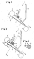
- the metal strip 2 is fed to the winding mandrel 3 by a blowing apparatus or driver, of which only the upper and lower drive rollers 5, 6 are shown. From the lower drive roller 6 is followed by the winding mandrel 3 below the metal strip 2, a table 7 at. The beginning or the tip of the thus-fed metal strip 2 is received by a first, the winding mandrel 3 associated pressure roller 8, the distributed distributed over the circumference further such roles.
- a band switch 9 which rests in the waiting position for tape recording on the upper drive roller 5.
- the band switch 9 is pivoted by a cylinder 10 which engages with its piston rod to a pivot arm of the band switch 9.
- the reel shaft 1 is closed at the top by a guided from the band switch 9 to the winding mandrel 3 shaft flap 11.
- a cylinder 12 is articulated to this.
- a strip tension measuring device 13 which at the same time fulfills the band softening function.
- This consists of a rear or drive side pivot arm 14 and a front-side pivot arm 14, of which in Fig. 2 the rear / drive side pivot arm can be seen.
- the two pivot arms 14 are by a torsion load receiving turnout body 15 (see. Fig. 4 ) connected with each other.
- it has a roller arm 16, in whose front end a driven roller 17 is mounted.
- the roller arm 16 is rotatably supported by a hinge 18. In order to avoid tilting due to gravity, the roller arm 16 is held in position by a retaining element 19.
- This can be controlled as a result of the measurement, for example, by pivoting the upper and / or lower drive roller 5, 6 or parallel pivoting both roles or by specifying different closing forces on the drive and operating side that arise on the winding mandrel 3 a straight edge coil 4 can.
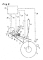
- the strip tension measuring device 13 is formed at its rear end in the tape running direction, away from the roller 17 with a provided in its axis of rotation switch point 23, as in the Fig. 2 and 3 shown as a cross section in the region of the pivot arm 7 through the pin of the switch roller 23.
- the reel shaft 1 is closed at the top by a pivotable by means of the cylinder 12 shaft flap 11.
- the below the metal strip 2 from the lower drive roller 6 to the mandrel 3 extending, the metal strip 2 conductive table 7 is formed at least at its front end with a pivotable about the axis of the lower drive roller 6 counterclockwise pivoting table 24.
- Fig. 3 which shows the operating position shortly before the end of a reeling operation for winding the metal strip 2 to a finished coil 4
- the wrap angle that forms the metal strip 2 due to the dipping roller 17 of the strip tension measuring device 13.
- different measured signals 25 or control signals 26 are indicated by dashed lines, which enter the control device 22 or depart from it to pivot means of the upper and lower drive rollers 5, 6 (see the dashed lines 26).
- the parameters which are essential for determining and, if necessary, maintaining an optimum wrap angle during the entire winding process are determined, for example, by detection the stroke of the swivel cylinder or the swivel cylinder 10 of the strip tension measuring device 13, wherein the / the cylinder are equipped with a displacement meter, determined by an angle measurement of the strip tension measuring device 13 and the current diameter of the coil 4.
- This diameter can be determined from the counted revolutions of the mandrel 3 (cf the dotted line 25 emanating therefrom) and the strip thickness.
- a direct measurement of the diameter of the coil 4 is possible, as with an indicated laser-optical measuring means 27.
- a measurement signal from the strip tension measurement in the reel shaft of a driver control can also be done in the combination strip tension measuring device / band switch by the combination strip tension measuring device / shaft cap.
- the in the Fig. 2 and 3 shown strip tension measuring device 13 would then be arranged with its role 17 to the winding mandrel 3 integrated into the shaft flap 11, ie, over the line AA of Fig. 2 mirrored.
- the space then free from the upper drive roller 5 to the strip tension measuring device 13 could in this option be combined with a conventional band switch 9 (cf. Fig. 1 ) filled or bridged.
Landscapes
- Engineering & Computer Science (AREA)
- Mechanical Engineering (AREA)
- Winding, Rewinding, Material Storage Devices (AREA)
- Controlling Rewinding, Feeding, Winding, Or Abnormalities Of Webs (AREA)
Applications Claiming Priority (3)
| Application Number | Priority Date | Filing Date | Title |
|---|---|---|---|
| DE102006045608 | 2006-09-25 | ||
| DE102007045425A DE102007045425A1 (de) | 2006-09-25 | 2007-09-21 | Verfahren und Vorrichtung zum Aufwickeln von Metallbändern auf einen Wickeldorn |
| PCT/EP2007/008217 WO2008037395A1 (de) | 2006-09-25 | 2007-09-21 | Verfahren und vorrichtung zum aufwickeln von metallbändern auf einen wickeldorn |
Publications (2)
| Publication Number | Publication Date |
|---|---|
| EP2109510A1 EP2109510A1 (de) | 2009-10-21 |
| EP2109510B1 true EP2109510B1 (de) | 2014-02-12 |
Family
ID=39185155
Family Applications (1)
| Application Number | Title | Priority Date | Filing Date |
|---|---|---|---|
| EP07818307.6A Active EP2109510B1 (de) | 2006-09-25 | 2007-09-21 | Verfahren und vorrichtung zum aufwickeln von metallbändern auf einen wickeldorn |
Country Status (10)
| Country | Link |
|---|---|
| US (1) | US20100025514A1 (enExample) |
| EP (1) | EP2109510B1 (enExample) |
| JP (1) | JP2010504216A (enExample) |
| KR (1) | KR101071117B1 (enExample) |
| CN (1) | CN101516539B (enExample) |
| BR (1) | BRPI0716770B1 (enExample) |
| CA (1) | CA2664263C (enExample) |
| DE (1) | DE102007045425A1 (enExample) |
| RU (1) | RU2391167C1 (enExample) |
| WO (1) | WO2008037395A1 (enExample) |
Families Citing this family (13)
| Publication number | Priority date | Publication date | Assignee | Title |
|---|---|---|---|---|
| DE102009058875A1 (de) | 2009-12-18 | 2011-07-07 | SMS Siemag AG, 40237 | Haspelvorrichtung und Verfahren zum Betreiben einer Haspelvorrichtung |
| KR101421814B1 (ko) * | 2012-11-02 | 2014-07-22 | 주식회사 포스코 | 권취유도장치 |
| DE102012224351A1 (de) * | 2012-12-21 | 2014-06-26 | Sms Siemag Ag | Verfahren und Vorrichtung zum Wickeln eines Metallbandes |
| US9718083B2 (en) | 2013-11-14 | 2017-08-01 | Illinois Tool Works Inc. | Fluid application device having a modular nozzle assembly for applying fluid to an article |
| US9908137B2 (en) | 2013-11-14 | 2018-03-06 | Illinois Tool Works Inc. | Fluid application device having a modular non-contact nozzle for applying fluid to an article |
| US9932704B2 (en) * | 2013-11-22 | 2018-04-03 | Illinois Tool Works Inc. | Fluid application device, strand engagement device and method of controlling the same |
| CN103743953B (zh) * | 2013-12-29 | 2017-01-04 | 中国计量学院 | 热双金属带材电阻随动同步连续测量系统 |
| MX374255B (es) * | 2015-05-18 | 2025-03-05 | Danieli Off Mecc | Unidad tensora para aparato de laminación. |
| PL226814B1 (pl) * | 2015-05-29 | 2017-09-29 | Przedsiębiorstwo Concept Stal B&S Lejman Spółka Jawna | Zwijarka doblachy |
| CN107774728A (zh) * | 2016-08-31 | 2018-03-09 | 扬中凯悦铜材有限公司 | 铜排拉拔收卷一体化装置 |
| CN109650123A (zh) * | 2019-02-27 | 2019-04-19 | 中冶赛迪工程技术股份有限公司 | 一种带钢穿带装置及方法 |
| WO2021150315A1 (en) | 2020-01-22 | 2021-07-29 | Novelis Inc. | Sensing and offsetting the force of events in a coil forming operation |
| ES2966258T3 (es) * | 2020-12-23 | 2024-04-19 | Primetals Technologies Austria GmbH | Dispositivo de bobinado para una amplia gama de grosores de bandas metálicas |
Family Cites Families (22)
| Publication number | Priority date | Publication date | Assignee | Title |
|---|---|---|---|---|
| JPS51127988A (en) * | 1975-04-30 | 1976-11-08 | Ishikawajima Harima Heavy Ind Co Ltd | Tension control device having looper and this looper |
| DE2911621A1 (de) * | 1978-03-31 | 1979-10-04 | Loewy Robertson Eng Co Ltd | Verfahren zum betreiben eines walzwerks zur erzeugung von metallbaendern |
| JPS5865674A (ja) * | 1981-10-16 | 1983-04-19 | Ricoh Co Ltd | プリンタ |
| JPS60231516A (ja) * | 1984-04-28 | 1985-11-18 | Sumitomo Metal Ind Ltd | ル−パ機構を有する巻取機 |
| DE3507251A1 (de) * | 1985-03-01 | 1986-09-04 | SMS Schloemann-Siemag AG, 4000 Düsseldorf | Treibapparat fuer walzband |
| GB8608494D0 (en) * | 1986-04-08 | 1986-05-14 | Davy Mckee Sheffield | Strip guiding for downcoilers |
| JPH01109314U (enExample) * | 1988-01-20 | 1989-07-24 | ||
| SE461298B (sv) * | 1988-06-02 | 1990-01-29 | Asea Brown Boveri | Planhetsmaetare foer valsade band |
| CN2198987Y (zh) * | 1994-08-23 | 1995-05-31 | 陈平 | 型钢绕带式压力容器的绕带装置 |
| DE19520709A1 (de) * | 1995-06-09 | 1996-12-12 | Schloemann Siemag Ag | Treiber für Walzbänder |
| JPH10137846A (ja) * | 1996-11-06 | 1998-05-26 | Mitsubishi Heavy Ind Ltd | 熱間圧延設備の帯鋼巻取り装置 |
| DE19704447A1 (de) * | 1997-02-06 | 1998-08-13 | Schloemann Siemag Ag | Planheitsmeßrolle |
| DE19818207C2 (de) * | 1998-04-23 | 2000-05-31 | Schloemann Siemag Ag | Steckel-Warmwalzwerk |
| US6039283A (en) * | 1998-05-19 | 2000-03-21 | Hylsa S.A. De C.V. | Thin strip coiling system |
| US6146411A (en) * | 1998-12-24 | 2000-11-14 | Alsius Corporation | Cooling system for indwelling heat exchange catheter |
| IT1306927B1 (it) * | 1999-01-11 | 2001-10-11 | Demag Italimpianti Spa | Laminatoio a caldo per nastri sottili con avvolgimento ad altavelocita' di nastri singoli |
| US6321052B1 (en) * | 1999-09-08 | 2001-11-20 | Fuji Xerox Co., Ltd. | Method and apparatus for correcting running state and tension for an endless belt in an image-forming apparatus |
| DE19953524A1 (de) * | 1999-11-05 | 2001-05-10 | Sms Demag Ag | Schlingenheber |
| US6722087B1 (en) * | 2000-09-21 | 2004-04-20 | Mic Industries | Building panel and panel crimping machine |
| DE10131850B4 (de) * | 2001-06-30 | 2013-04-25 | Sms Siemag Aktiengesellschaft | Dünnbandhaspel mit Planheitsmeßrolle |
| FI114391B (fi) * | 2002-04-30 | 2004-10-15 | Pesmel Oy | Kehäratarakenteen käsittävä käärintälaitteisto ja kalvonjakolaitteisto |
| DE10258499A1 (de) * | 2002-12-14 | 2004-07-01 | Sms Demag Ag | Umlenkvorrichtung einer Haspelanlage zum Aufhaspeln von Bändern |
-
2007
- 2007-09-21 EP EP07818307.6A patent/EP2109510B1/de active Active
- 2007-09-21 US US12/442,715 patent/US20100025514A1/en not_active Abandoned
- 2007-09-21 CN CN2007800356368A patent/CN101516539B/zh active Active
- 2007-09-21 WO PCT/EP2007/008217 patent/WO2008037395A1/de not_active Ceased
- 2007-09-21 DE DE102007045425A patent/DE102007045425A1/de not_active Withdrawn
- 2007-09-21 BR BRPI0716770-9A patent/BRPI0716770B1/pt active IP Right Grant
- 2007-09-21 JP JP2009528648A patent/JP2010504216A/ja active Pending
- 2007-09-21 KR KR1020097003037A patent/KR101071117B1/ko active Active
- 2007-09-21 CA CA2664263A patent/CA2664263C/en not_active Expired - Fee Related
- 2007-09-21 RU RU2009115695/02A patent/RU2391167C1/ru active
Also Published As
| Publication number | Publication date |
|---|---|
| RU2391167C1 (ru) | 2010-06-10 |
| US20100025514A1 (en) | 2010-02-04 |
| CA2664263A1 (en) | 2008-04-03 |
| BRPI0716770B1 (pt) | 2019-03-26 |
| WO2008037395A1 (de) | 2008-04-03 |
| CN101516539A (zh) | 2009-08-26 |
| KR101071117B1 (ko) | 2011-10-07 |
| CN101516539B (zh) | 2012-02-15 |
| CA2664263C (en) | 2011-04-19 |
| BRPI0716770A2 (pt) | 2013-09-17 |
| DE102007045425A1 (de) | 2008-04-17 |
| EP2109510A1 (de) | 2009-10-21 |
| JP2010504216A (ja) | 2010-02-12 |
| KR20090031622A (ko) | 2009-03-26 |
Similar Documents
| Publication | Publication Date | Title |
|---|---|---|
| EP2109510B1 (de) | Verfahren und vorrichtung zum aufwickeln von metallbändern auf einen wickeldorn | |
| EP2069088B1 (de) | Verfahren und vorrichtung zum aufwickeln von metallbändern auf einen wickeldorn | |
| DE2618901C2 (de) | Vorrichtung zur Bandzugregelung in einer kontinuierlichen Walzstraße | |
| DE10131850B4 (de) | Dünnbandhaspel mit Planheitsmeßrolle | |
| EP1278606B1 (de) | Verfahren und vorrichtung zum lagegerechten aufwickeln eines gewalzten warmbandes in einer haspelvorrichtung | |
| EP1908534B1 (de) | Walzwerk und Verfahren zum flexiblen Kalt- oder Warm-Einweg- oder Reversierwalzen von Metallband | |
| EP1784266B1 (de) | Walzwerk zum walzen von metallischem band | |
| EP1097754B1 (de) | Schlingenheber | |
| WO2020156787A1 (de) | Verändern der effektiven kontur einer lauffläche einer arbeitswalze während des warmwalzens eines walzguts in einem walzgerüst zu einem gewalzten band | |
| WO2012045607A1 (de) | Treiber für eine stahlbandhaspelanlage | |
| EP0817688B1 (de) | Bandhaspel | |
| DE2911881A1 (de) | Schlingenheber | |
| EP1763410B1 (de) | Verfahren und vorrichtung zur reduktion von schwingungen in einem steckelwalzwerk | |
| DE102013207188A1 (de) | Vorrichtung und Verfahren zum dornlosen Aufwickeln eines Metallbandes | |
| DE2600784C3 (de) | Verfahren zum Walzen von Warmband und Warmbandwalzwerk zur Durchführung des Verfahrens | |
| EP2398604A2 (de) | Bandhaspel zum anwickeln und fertigwickeln von metallbändern | |
| EP2637807B1 (de) | Walzstrasse zum walzen eines metallbandes | |
| AT510468B1 (de) | Durchlaufofen für ein insbesondere metallisches band | |
| EP2745948A1 (de) | Haspeleinrichtung mit rückbiegbarer Haspelwelle | |
| DE1995821U (de) | Vorrichtung zum aufwickeln bahnfoermiger materialien. | |
| DE102009053860A1 (de) | Schlingenheber | |
| DE102011089744A1 (de) | Geschwindigkeitsmessvorrichtung, insbesondere zur Warmbandgeschwindigkeitsmessung im Zwischengerüstbereich | |
| DE102009053858A1 (de) | Schlingenheber | |
| DE29511051U1 (de) | Vorziehmaschine |
Legal Events
| Date | Code | Title | Description |
|---|---|---|---|
| PUAI | Public reference made under article 153(3) epc to a published international application that has entered the european phase |
Free format text: ORIGINAL CODE: 0009012 |
|
| 17P | Request for examination filed |
Effective date: 20090427 |
|
| AK | Designated contracting states |
Kind code of ref document: A1 Designated state(s): AT BE BG CH CY CZ DE DK EE ES FI FR GB GR HU IE IS IT LI LT LU LV MC MT NL PL PT RO SE SI SK TR |
|
| DAX | Request for extension of the european patent (deleted) | ||
| GRAP | Despatch of communication of intention to grant a patent |
Free format text: ORIGINAL CODE: EPIDOSNIGR1 |
|
| INTG | Intention to grant announced |
Effective date: 20130920 |
|
| GRAS | Grant fee paid |
Free format text: ORIGINAL CODE: EPIDOSNIGR3 |
|
| GRAA | (expected) grant |
Free format text: ORIGINAL CODE: 0009210 |
|
| AK | Designated contracting states |
Kind code of ref document: B1 Designated state(s): AT BE BG CH CY CZ DE DK EE ES FI FR GB GR HU IE IS IT LI LT LU LV MC MT NL PL PT RO SE SI SK TR |
|
| REG | Reference to a national code |
Ref country code: GB Ref legal event code: FG4D Free format text: NOT ENGLISH |
|
| REG | Reference to a national code |
Ref country code: CH Ref legal event code: EP |
|
| REG | Reference to a national code |
Ref country code: AT Ref legal event code: REF Ref document number: 651898 Country of ref document: AT Kind code of ref document: T Effective date: 20140215 |
|
| REG | Reference to a national code |
Ref country code: IE Ref legal event code: FG4D Free format text: LANGUAGE OF EP DOCUMENT: GERMAN |
|
| REG | Reference to a national code |
Ref country code: DE Ref legal event code: R096 Ref document number: 502007012760 Country of ref document: DE Effective date: 20140327 |
|
| REG | Reference to a national code |
Ref country code: NL Ref legal event code: VDEP Effective date: 20140212 |
|
| REG | Reference to a national code |
Ref country code: LT Ref legal event code: MG4D |
|
| PG25 | Lapsed in a contracting state [announced via postgrant information from national office to epo] |
Ref country code: LT Free format text: LAPSE BECAUSE OF FAILURE TO SUBMIT A TRANSLATION OF THE DESCRIPTION OR TO PAY THE FEE WITHIN THE PRESCRIBED TIME-LIMIT Effective date: 20140212 Ref country code: IS Free format text: LAPSE BECAUSE OF FAILURE TO SUBMIT A TRANSLATION OF THE DESCRIPTION OR TO PAY THE FEE WITHIN THE PRESCRIBED TIME-LIMIT Effective date: 20140612 |
|
| PG25 | Lapsed in a contracting state [announced via postgrant information from national office to epo] |
Ref country code: FI Free format text: LAPSE BECAUSE OF FAILURE TO SUBMIT A TRANSLATION OF THE DESCRIPTION OR TO PAY THE FEE WITHIN THE PRESCRIBED TIME-LIMIT Effective date: 20140212 Ref country code: ES Free format text: LAPSE BECAUSE OF FAILURE TO SUBMIT A TRANSLATION OF THE DESCRIPTION OR TO PAY THE FEE WITHIN THE PRESCRIBED TIME-LIMIT Effective date: 20140212 Ref country code: NL Free format text: LAPSE BECAUSE OF FAILURE TO SUBMIT A TRANSLATION OF THE DESCRIPTION OR TO PAY THE FEE WITHIN THE PRESCRIBED TIME-LIMIT Effective date: 20140212 Ref country code: CY Free format text: LAPSE BECAUSE OF FAILURE TO SUBMIT A TRANSLATION OF THE DESCRIPTION OR TO PAY THE FEE WITHIN THE PRESCRIBED TIME-LIMIT Effective date: 20140212 Ref country code: SE Free format text: LAPSE BECAUSE OF FAILURE TO SUBMIT A TRANSLATION OF THE DESCRIPTION OR TO PAY THE FEE WITHIN THE PRESCRIBED TIME-LIMIT Effective date: 20140212 Ref country code: PT Free format text: LAPSE BECAUSE OF FAILURE TO SUBMIT A TRANSLATION OF THE DESCRIPTION OR TO PAY THE FEE WITHIN THE PRESCRIBED TIME-LIMIT Effective date: 20140612 |
|
| PG25 | Lapsed in a contracting state [announced via postgrant information from national office to epo] |
Ref country code: LV Free format text: LAPSE BECAUSE OF FAILURE TO SUBMIT A TRANSLATION OF THE DESCRIPTION OR TO PAY THE FEE WITHIN THE PRESCRIBED TIME-LIMIT Effective date: 20140212 |
|
| PG25 | Lapsed in a contracting state [announced via postgrant information from national office to epo] |
Ref country code: CZ Free format text: LAPSE BECAUSE OF FAILURE TO SUBMIT A TRANSLATION OF THE DESCRIPTION OR TO PAY THE FEE WITHIN THE PRESCRIBED TIME-LIMIT Effective date: 20140212 Ref country code: EE Free format text: LAPSE BECAUSE OF FAILURE TO SUBMIT A TRANSLATION OF THE DESCRIPTION OR TO PAY THE FEE WITHIN THE PRESCRIBED TIME-LIMIT Effective date: 20140212 Ref country code: DK Free format text: LAPSE BECAUSE OF FAILURE TO SUBMIT A TRANSLATION OF THE DESCRIPTION OR TO PAY THE FEE WITHIN THE PRESCRIBED TIME-LIMIT Effective date: 20140212 Ref country code: RO Free format text: LAPSE BECAUSE OF FAILURE TO SUBMIT A TRANSLATION OF THE DESCRIPTION OR TO PAY THE FEE WITHIN THE PRESCRIBED TIME-LIMIT Effective date: 20140212 |
|
| REG | Reference to a national code |
Ref country code: DE Ref legal event code: R097 Ref document number: 502007012760 Country of ref document: DE |
|
| PG25 | Lapsed in a contracting state [announced via postgrant information from national office to epo] |
Ref country code: PL Free format text: LAPSE BECAUSE OF FAILURE TO SUBMIT A TRANSLATION OF THE DESCRIPTION OR TO PAY THE FEE WITHIN THE PRESCRIBED TIME-LIMIT Effective date: 20140212 Ref country code: SK Free format text: LAPSE BECAUSE OF FAILURE TO SUBMIT A TRANSLATION OF THE DESCRIPTION OR TO PAY THE FEE WITHIN THE PRESCRIBED TIME-LIMIT Effective date: 20140212 |
|
| PLBE | No opposition filed within time limit |
Free format text: ORIGINAL CODE: 0009261 |
|
| STAA | Information on the status of an ep patent application or granted ep patent |
Free format text: STATUS: NO OPPOSITION FILED WITHIN TIME LIMIT |
|
| 26N | No opposition filed |
Effective date: 20141113 |
|
| REG | Reference to a national code |
Ref country code: DE Ref legal event code: R097 Ref document number: 502007012760 Country of ref document: DE Effective date: 20141113 |
|
| PG25 | Lapsed in a contracting state [announced via postgrant information from national office to epo] |
Ref country code: MC Free format text: LAPSE BECAUSE OF FAILURE TO SUBMIT A TRANSLATION OF THE DESCRIPTION OR TO PAY THE FEE WITHIN THE PRESCRIBED TIME-LIMIT Effective date: 20140212 Ref country code: LU Free format text: LAPSE BECAUSE OF FAILURE TO SUBMIT A TRANSLATION OF THE DESCRIPTION OR TO PAY THE FEE WITHIN THE PRESCRIBED TIME-LIMIT Effective date: 20140921 |
|
| REG | Reference to a national code |
Ref country code: CH Ref legal event code: PL |
|
| GBPC | Gb: european patent ceased through non-payment of renewal fee |
Effective date: 20140921 |
|
| PG25 | Lapsed in a contracting state [announced via postgrant information from national office to epo] |
Ref country code: SI Free format text: LAPSE BECAUSE OF FAILURE TO SUBMIT A TRANSLATION OF THE DESCRIPTION OR TO PAY THE FEE WITHIN THE PRESCRIBED TIME-LIMIT Effective date: 20140212 |
|
| REG | Reference to a national code |
Ref country code: IE Ref legal event code: MM4A |
|
| REG | Reference to a national code |
Ref country code: FR Ref legal event code: ST Effective date: 20150529 |
|
| PG25 | Lapsed in a contracting state [announced via postgrant information from national office to epo] |
Ref country code: BE Free format text: LAPSE BECAUSE OF NON-PAYMENT OF DUE FEES Effective date: 20140930 |
|
| PG25 | Lapsed in a contracting state [announced via postgrant information from national office to epo] |
Ref country code: CH Free format text: LAPSE BECAUSE OF NON-PAYMENT OF DUE FEES Effective date: 20140930 Ref country code: LI Free format text: LAPSE BECAUSE OF NON-PAYMENT OF DUE FEES Effective date: 20140930 Ref country code: GB Free format text: LAPSE BECAUSE OF NON-PAYMENT OF DUE FEES Effective date: 20140921 |
|
| REG | Reference to a national code |
Ref country code: DE Ref legal event code: R082 Ref document number: 502007012760 Country of ref document: DE Representative=s name: HEMMERICH & KOLLEGEN, DE Ref country code: DE Ref legal event code: R081 Ref document number: 502007012760 Country of ref document: DE Owner name: SMS GROUP GMBH, DE Free format text: FORMER OWNER: SMS SIEMAG AG, 40237 DUESSELDORF, DE |
|
| PG25 | Lapsed in a contracting state [announced via postgrant information from national office to epo] |
Ref country code: IE Free format text: LAPSE BECAUSE OF NON-PAYMENT OF DUE FEES Effective date: 20140921 Ref country code: FR Free format text: LAPSE BECAUSE OF NON-PAYMENT OF DUE FEES Effective date: 20140930 |
|
| PG25 | Lapsed in a contracting state [announced via postgrant information from national office to epo] |
Ref country code: BG Free format text: LAPSE BECAUSE OF FAILURE TO SUBMIT A TRANSLATION OF THE DESCRIPTION OR TO PAY THE FEE WITHIN THE PRESCRIBED TIME-LIMIT Effective date: 20140212 |
|
| PG25 | Lapsed in a contracting state [announced via postgrant information from national office to epo] |
Ref country code: MT Free format text: LAPSE BECAUSE OF FAILURE TO SUBMIT A TRANSLATION OF THE DESCRIPTION OR TO PAY THE FEE WITHIN THE PRESCRIBED TIME-LIMIT Effective date: 20140212 Ref country code: GR Free format text: LAPSE BECAUSE OF FAILURE TO SUBMIT A TRANSLATION OF THE DESCRIPTION OR TO PAY THE FEE WITHIN THE PRESCRIBED TIME-LIMIT Effective date: 20140513 |
|
| PG25 | Lapsed in a contracting state [announced via postgrant information from national office to epo] |
Ref country code: HU Free format text: LAPSE BECAUSE OF FAILURE TO SUBMIT A TRANSLATION OF THE DESCRIPTION OR TO PAY THE FEE WITHIN THE PRESCRIBED TIME-LIMIT; INVALID AB INITIO Effective date: 20070921 Ref country code: TR Free format text: LAPSE BECAUSE OF FAILURE TO SUBMIT A TRANSLATION OF THE DESCRIPTION OR TO PAY THE FEE WITHIN THE PRESCRIBED TIME-LIMIT Effective date: 20140212 |
|
| P01 | Opt-out of the competence of the unified patent court (upc) registered |
Effective date: 20230707 |
|
| PGFP | Annual fee paid to national office [announced via postgrant information from national office to epo] |
Ref country code: DE Payment date: 20240918 Year of fee payment: 18 |
|
| PGFP | Annual fee paid to national office [announced via postgrant information from national office to epo] |
Ref country code: AT Payment date: 20240919 Year of fee payment: 18 |
|
| PGFP | Annual fee paid to national office [announced via postgrant information from national office to epo] |
Ref country code: IT Payment date: 20240924 Year of fee payment: 18 |