EP2108287A1 - Federende-anbringvorrichtung - Google Patents
Federende-anbringvorrichtung Download PDFInfo
- Publication number
- EP2108287A1 EP2108287A1 EP08704386A EP08704386A EP2108287A1 EP 2108287 A1 EP2108287 A1 EP 2108287A1 EP 08704386 A EP08704386 A EP 08704386A EP 08704386 A EP08704386 A EP 08704386A EP 2108287 A1 EP2108287 A1 EP 2108287A1
- Authority
- EP
- European Patent Office
- Prior art keywords
- spring
- collar
- round shaft
- retainer
- spring engagement
- Prior art date
- Legal status (The legal status is an assumption and is not a legal conclusion. Google has not performed a legal analysis and makes no representation as to the accuracy of the status listed.)
- Granted
Links
- 230000000630 rising effect Effects 0.000 claims description 2
- 238000004519 manufacturing process Methods 0.000 description 4
- 239000011347 resin Substances 0.000 description 4
- 229920005989 resin Polymers 0.000 description 4
- 239000011248 coating agent Substances 0.000 description 3
- 238000000576 coating method Methods 0.000 description 3
- 230000005489 elastic deformation Effects 0.000 description 2
- -1 for example Substances 0.000 description 2
- 230000014509 gene expression Effects 0.000 description 2
- 239000002184 metal Substances 0.000 description 2
- 239000004743 Polypropylene Substances 0.000 description 1
- 229910000831 Steel Inorganic materials 0.000 description 1
- 239000000463 material Substances 0.000 description 1
- 239000007769 metal material Substances 0.000 description 1
- 238000012986 modification Methods 0.000 description 1
- 230000004048 modification Effects 0.000 description 1
- 229920001155 polypropylene Polymers 0.000 description 1
- 230000000717 retained effect Effects 0.000 description 1
- 239000010959 steel Substances 0.000 description 1
Images


Classifications
-
- B—PERFORMING OPERATIONS; TRANSPORTING
- B60—VEHICLES IN GENERAL
- B60N—SEATS SPECIALLY ADAPTED FOR VEHICLES; VEHICLE PASSENGER ACCOMMODATION NOT OTHERWISE PROVIDED FOR
- B60N2/00—Seats specially adapted for vehicles; Arrangement or mounting of seats in vehicles
- B60N2/70—Upholstery springs ; Upholstery
- B60N2/72—Attachment or adjustment thereof
-
- A—HUMAN NECESSITIES
- A47—FURNITURE; DOMESTIC ARTICLES OR APPLIANCES; COFFEE MILLS; SPICE MILLS; SUCTION CLEANERS IN GENERAL
- A47C—CHAIRS; SOFAS; BEDS
- A47C7/00—Parts, details, or accessories of chairs or stools
- A47C7/02—Seat parts
- A47C7/28—Seat parts with tensioned springs, e.g. of flat type
- A47C7/285—Seat parts with tensioned springs, e.g. of flat type with metal strips or webs
-
- B—PERFORMING OPERATIONS; TRANSPORTING
- B60—VEHICLES IN GENERAL
- B60N—SEATS SPECIALLY ADAPTED FOR VEHICLES; VEHICLE PASSENGER ACCOMMODATION NOT OTHERWISE PROVIDED FOR
- B60N2/00—Seats specially adapted for vehicles; Arrangement or mounting of seats in vehicles
- B60N2/70—Upholstery springs ; Upholstery
- B60N2/7023—Coach-like constructions
- B60N2/7035—Cushions
- B60N2/7041—Fixation of covers and springs
-
- B—PERFORMING OPERATIONS; TRANSPORTING
- B60—VEHICLES IN GENERAL
- B60N—SEATS SPECIALLY ADAPTED FOR VEHICLES; VEHICLE PASSENGER ACCOMMODATION NOT OTHERWISE PROVIDED FOR
- B60N2/00—Seats specially adapted for vehicles; Arrangement or mounting of seats in vehicles
- B60N2/70—Upholstery springs ; Upholstery
- B60N2/7094—Upholstery springs
-
- F—MECHANICAL ENGINEERING; LIGHTING; HEATING; WEAPONS; BLASTING
- F16—ENGINEERING ELEMENTS AND UNITS; GENERAL MEASURES FOR PRODUCING AND MAINTAINING EFFECTIVE FUNCTIONING OF MACHINES OR INSTALLATIONS; THERMAL INSULATION IN GENERAL
- F16B—DEVICES FOR FASTENING OR SECURING CONSTRUCTIONAL ELEMENTS OR MACHINE PARTS TOGETHER, e.g. NAILS, BOLTS, CIRCLIPS, CLAMPS, CLIPS OR WEDGES; JOINTS OR JOINTING
- F16B2/00—Friction-grip releasable fastenings
- F16B2/20—Clips, i.e. with gripping action effected solely by the inherent resistance to deformation of the material of the fastening
- F16B2/22—Clips, i.e. with gripping action effected solely by the inherent resistance to deformation of the material of the fastening of resilient material, e.g. rubbery material
- F16B2/24—Clips, i.e. with gripping action effected solely by the inherent resistance to deformation of the material of the fastening of resilient material, e.g. rubbery material of metal
- F16B2/241—Clips, i.e. with gripping action effected solely by the inherent resistance to deformation of the material of the fastening of resilient material, e.g. rubbery material of metal of sheet metal
-
- Y—GENERAL TAGGING OF NEW TECHNOLOGICAL DEVELOPMENTS; GENERAL TAGGING OF CROSS-SECTIONAL TECHNOLOGIES SPANNING OVER SEVERAL SECTIONS OF THE IPC; TECHNICAL SUBJECTS COVERED BY FORMER USPC CROSS-REFERENCE ART COLLECTIONS [XRACs] AND DIGESTS
- Y10—TECHNICAL SUBJECTS COVERED BY FORMER USPC
- Y10T—TECHNICAL SUBJECTS COVERED BY FORMER US CLASSIFICATION
- Y10T24/00—Buckles, buttons, clasps, etc.
- Y10T24/44—Clasp, clip, support-clamp, or required component thereof
- Y10T24/44034—Dissociable gripping members
- Y10T24/44043—Channel and inserted bar
- Y10T24/4406—Resilient channel or bar
-
- Y—GENERAL TAGGING OF NEW TECHNOLOGICAL DEVELOPMENTS; GENERAL TAGGING OF CROSS-SECTIONAL TECHNOLOGIES SPANNING OVER SEVERAL SECTIONS OF THE IPC; TECHNICAL SUBJECTS COVERED BY FORMER USPC CROSS-REFERENCE ART COLLECTIONS [XRACs] AND DIGESTS
- Y10—TECHNICAL SUBJECTS COVERED BY FORMER USPC
- Y10T—TECHNICAL SUBJECTS COVERED BY FORMER US CLASSIFICATION
- Y10T24/00—Buckles, buttons, clasps, etc.
- Y10T24/44—Clasp, clip, support-clamp, or required component thereof
- Y10T24/44641—Clasp, clip, support-clamp, or required component thereof having gripping member formed from, biased by, or mounted on resilient member
- Y10T24/44684—Clasp, clip, support-clamp, or required component thereof having gripping member formed from, biased by, or mounted on resilient member with operator for moving biased engaging face
- Y10T24/44692—Camming or wedging element
- Y10T24/44701—Encircling sleeve type element
-
- Y—GENERAL TAGGING OF NEW TECHNOLOGICAL DEVELOPMENTS; GENERAL TAGGING OF CROSS-SECTIONAL TECHNOLOGIES SPANNING OVER SEVERAL SECTIONS OF THE IPC; TECHNICAL SUBJECTS COVERED BY FORMER USPC CROSS-REFERENCE ART COLLECTIONS [XRACs] AND DIGESTS
- Y10—TECHNICAL SUBJECTS COVERED BY FORMER USPC
- Y10T—TECHNICAL SUBJECTS COVERED BY FORMER US CLASSIFICATION
- Y10T403/00—Joints and connections
- Y10T403/71—Rod side to plate or side
- Y10T403/7176—Resilient clip
Definitions
- the present invention relates to an attaching device for fixing end portions of springs to be stretched between opposing frame sections of a seat cushion frame for a seat and, more particularly, to an attaching device for fixing end portions of springs, each of which has a substantially U-shape in outline, to a round shaft which is employed as a frame section constituting one of opposing frame sections of a seat cushion frame for a seat.
- a vehicle seat As a vehicle seat, there has been proposed a vehicle seat in which a metal-made round shaft is employed as a rear frame section of a seat cushion frame for the seat, zigzag springs for supporting a cushion thereon are stretched between the round shaft and a forward frame section of the seat cushion frame, and end portions of the zigzag springs are fixed to the round shaft by a retainer (Japanese Patent Application Laid-Open No. 2006-14867 ).
- the retainer comprises a longitudinal body of a substantially U-shape in cross-section, and pairs of first and second spring engagement pieces provided at both longitudinal edges of the longitudinal body so as to be spaced apart from one another along the longitudinal edges, the first spring engagement pieces being bent laterally outwardly from one of the longitudinal edges of the longitudinal body and the second spring engagement pieces being bent laterally outwardly from the other of the longitudinal edges of the longitudinal body.
- the longitudinal body and the pairs of first and second spring engagement pieces are integrally formed from a metal plate by causing the metal plate to be bent.
- the retainer is adapted to be mounted on the round shaft with the substantially U-shaped longitudinal body being fitted over the round shaft, with the first spring engagement pieces being located inside the seat cushion frame, and with the second spring engagement pieces being located outside the seat cushion frame.
- Each of the end portions of the springs is formed substantially in a U-shape in outline and comprises first and second spaced apart axial regions and an intermediate axial region interconnecting the first and second spaced apart axial regions.
- the end portion of a spring is fixed to the round shaft through the retainer, with the first axial region and the second axial region being heldly engaged with a corresponding first spring engagement piece and a corresponding second spring engagement piece of the retainer, respectively, and with the intermediate axial region being located under the round shaft and engaged with the round shaft.
- An inner circumference of the substantially U-shaped longitudinal body of the retainer is dimensioned such that the longitudinal body can be fitted over an outer circumference of the round shaft. Therefore, when the zigzag springs are fixed at the end portions thereof to round shafts having various diameters, for example, about 22.2mm or 23.8mm, retainers whose substantially U-shaped longitudinal bodies have inner circumferential sizes that allow the retainers to be fitted over outer circumferences of the round shafts are required to be prepared for the round shafts having various diameters. Moreover, when the retainer which is formed of metal material is directly fitted over the metal-made round shaft, there is a possibility that noise will be produced by rubbing the metal-made retainer with the metal-made round shaft. In order to prevent the production of the noise, application of a resin coating onto the retainer is required, thus resulting in increased cost of the retainer.
- an attaching device for fixing an end portion of at least one spring for supporting a cushion for a seat, to a seat frame of the seat, wherein the seat frame includes opposing seat frame sections, one of the opposing seat frame sections being formed from a round shaft, the at least one spring being stretched between the opposing seat frame sections, the end portion of the at least one spring being formed substantially in a U-shape in outline and including first and second spaced apart axial regions and an intermediate axial region interconnecting the first and second spaced apart axial regions.
- the attaching device comprises a resin-made collar of a substantially U-shape in cross-section, and a metal-made retainer including a body having a geometry of similar figure with the collar, and at least one pair of first and second spring engagement pieces provided at both edges of the body, the first spring engagement piece extending downward from one of the both edges of the body and bent laterally outwardly at a lower end thereof for engaging with the first axial region of the at least one spring, the second spring engagement piece extending downward from the other of the both edges of the body and bent laterally outwardly at a lower end thereof for engaging with the second axial region of the at least one spring, the resin-made collar being adapted to be fitted over or mounted on the round shaft with an opening side thereof facing downward, the body of the retainer being adapted to be fitted over or mounted on the collar on the round shaft with the first spring engagement piece being located inside the seat frame and with the second spring engagement piece being located outside the seat frame, the first axial region and the second axial region of the at least one spring being adapted to
- the attaching device of the present invention which is constructed as discussed above comprises the resin-made collar having a substantially U-shape in cross-section and adapted to be fitted over the round shaft, and the metal-made retainer adapted to be fitted over the resin-made collar on the round shaft, so that even if there is a size difference between an outer circumference of the round shaft and an inner circumference of the resin-made collar, such a size difference can be easily cancelled by elastic deformation of the resin-made collar.
- the attaching device in a case where the attaching device is applied to a round shaft having a diameter slightly larger than the inner circumference of the collar, fitting of the collar over the round shaft can be easily performed while causing the collar to be deformed in such a manner that an opening of the collar is operatively widened. Even if the attaching device is applied to a round shaft having a diameter smaller than the inner circumference of the collar and a clearance between the round shaft and the collar is produced, production of noise between the attaching device and the round shaft can be effectively prevented by the resin-made collar. Therefore, in order to prevent the production of the noise, application of a resin coating or the like onto the attaching device is not required, thus resulting in reduced cost of the attaching device.
- the first spring engagement piece may be formed so as to have a length which allows the at least one spring to be stretched between the opposing frame sections at a reference height and the second spring engagement piece may be formed so as to have a length relatively shorter than the first spring engagement piece, so that the end portion of the at least one spring is adapted to be fixed to the round shaft with the second axial region thereof being engaged with the second spring engagement piece at a position higher than a position where the first axial region is engaged with the first spring engagement piece, and with the intermediate axial region becoming oblique.
- the rear end portion of the spring is interposedly held by the first and second spring engagement pieces with the second axial region thereof in engagement with the second spring engagement piece being situated at a height higher than the first axial region thereof in engagement with the first spring engagement piece, and with the intermediate axial region becoming oblique.
- the spring can be stably stretched between the opposing seat frame sections by the attaching device so as to be located at the reference height.
- a plurality of springs may be stretched between the opposing frame sections so as to be spaced apart from one another, and the collar and the body of the retainer may be formed longitudinally, the longitudinal body of the retainer having pairs of first and second spring engagement pieces provided at both edges of the longitudinal body, and the pairs of first and second spring engagement pieces corresponding in number to the springs.
- the collar which is adapted to be fitted over the round shaft is formed longitudinally and the retainer which includes the longitudinal body and the pairs of first and second spring engagement pieces provided at the both edges of the longitudinal body, so that end portions of the plurality of springs can be easily fixed to the single round shaft by the attaching device.
- the collar may have at least one elongated-protrusion rising up from a top surface thereof, and the body of the retainer may have at least one through-hole that is formed in a top surface of the body and adapted to be engagedly fitted over the at least one elongated-protrusion when the body of the retainer is mounted on the collar on the round shaft.
- the retainer can be prevented from being rotated or circumferentially shifted relative to the collar.
- the collar may have circumferential retaining-flanges provided around both ends thereof.
- both ends of the body of the retainer is adapted to be abutted against the circumferential retaining-flanges when the body of the retainer is fitted over the collar on the round shaft, whereby the body of the retainer is positioned relative to the collar by the circumferential retaining-flanges.
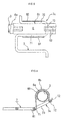
- a seat cushion frame for a slide-type vehicle seat in which springs are employed as means to support a cushion for a seat cushion of the vehicle seat and fixed at end portions thereof to the seat cushion frame by an attaching device 6 for fixing end portions of springs according to an embodiment of the present invention.
- the seat cushion frame comprises a pair of spaced apart left and right side frame sections 1 a, 1b, a pair of spaced apart upper rail members 2a, 2b integrally attached to the side frame sections 1 a, 1b, a round shaft 3 formed from a round pipe or round rod, the round shaft 3 being attached between rear end portions of the side frame sections 1 a, 1b, and a pan frame member 4 attached between forward end portions of the side frame sections 1 a, 1 b.
- reference numerals 5a, 5b denote lower rail members to which the upper rail members 2a, 2b are slidably supported.
- a plurality of springs 7, each of which constitutes a zigzag spring comprising a plurality of substantially U-shaped axial portions continuously connected to one another, are stretched between the round shaft 3 and the pan frame member 4 so as to be arranged in parallel with one another and spaced apart from one another.
- the springs 7 are horizontally stretched between the round shaft 3 and the pan frame member 4 by causing rear end portions 7a of the springs 7 to be fixed to the round shaft 3 through the attaching device 6 and by causing forward end portions of the springs 7 to be hooked on loop-shaped engaging pieces 8 which are provided at the pan frame member 4 by causing regions of the pan frame member 4 to be cut and then causing the cut regions of the pan frame member 4 to be raised up from a surface of the pan frame member 4.
- the attaching device 6 is designed such that it can fix rear end portions of four springs 7 (see Fig. 1 ) to the single round shaft 3 while allowing the springs 7 to be spaced apart from one another.
- the attaching device 6 comprises a resin-made longitudinal collar 6a formed of elastically deformable resin material, for example, polypropylene or the like, and a metal-made retainer 6b formed of, for example, thin steel plate.
- the resin-made longitudinal collar 6a is configured so as to have a substantially U-shape in cross-section which allows the longitudinal collar 6a to be mounted on or fitted over the round shaft 3.
- the longitudinal collar 6a is fitted over the round shaft 3 with an opening side thereof facing downwardly.
- the longitudinal collar 6a is configured so as to have a length which is enough for allowing the rear end portions of the four springs 7 to be fixed to the round shaft 3.
- the metal-made retainer 6b comprises a longitudinal body 60 of a substantially U-shape in cross-section and four pairs of spring engagement pieces 61, 62 (only one pair of spring engagement pieces 61, 62 are best shown in Figs. 2 and 3 ) provided along both longitudinal edges of the substantially U-shaped longitudinal body 60 so as to be spaced apart from one another in the longitudinal direction of the longitudinal body 60.
- the longitudinal body 60 of the metal-made retainer 6b is mounted on or fitted over the collar 6a fitted over the round shaft 3, with an opening side thereof facing downwardly. More particularly, the longitudinal body 60 of the retainer 6b is configured so as to have a geometry of similar figure with the collar 6a and an inner circumference size that allows the longitudinal body 60 of the retainer 6b to be fitted over an outer circumference of the longitudinal collar 6a.
- the longitudinal collar 6a has three pairs of spaced apart elongated protrusions 63 which rise up from a longitudinal top surface of the longitudinal collar 6a in a state of being fitted over the round shaft 3 and are arranged so as to be spaced apart from one another in the longitudinal direction of the longitudinal collar 6a.
- the longitudinal body 60 of the retainer 6b has three through-holes 64 which are formed in a longitudinal top surface of the longitudinal body 60 in a state of being fitted over the collar 6a and in which the protrusions 63 of the retainer 6b are fitted.
- the through-holes 64 are formed in the longitudinal top surface of the longitudinal body 60 which are remote from regions of the longitudinal body 60 at which the spring engagement pieces 61, 62 are provided.
- the longitudinal collar 6a further has circumferential retaining-flanges 65a, 65b provided around both end portions thereof.
- both ends of the longitudinal body 60 of the retainer 6b are abutted against the circumferential retaining-flanges 65a, 65b of the collar 6 whereby the longitudinal body 60 of the retainer 6b are positioned with respect to the collar 6a through the circumferential retaining-flanges 65a, 65b.
- the both end portions of the collar 6a has circumferential ribs 66a, 66b provided around edges thereof.
- the collar 6a and the retainer 6b are provided as separate components and any resin coating or the like is not required to be applied to the attaching device, thus realizing a decrease in cost.
- the attaching device 6 constructed as discussed above is applied to the round shaft 3 with the resin-made collar 6a being fitted over the round shaft 3 and with the metal-made retainer 6b being fitted over the collar 6a on the round shaft 3.
- the first spring engagement pieces 61 of the retainer 6b fitted over the collar 6a downward extend beyond the round shaft and are located inside the seat cushion frame and the second spring engagement pieces 62 of the retainer 6b downward extend beyond the round shaft 3 and are located outside the seat cushion frame.
- first spring engagement pieces 61 and the second spring engagement pieces 62 extend downward from one of the both longitudinal edges of the longitudinal body 60 of the retainer 6b and the other of the both longitudinal edges of the longitudinal body 60, respectively, and are laterally outwardly bent at lower ends thereof in the opposite directions.
- Each of the first spring engagement pieces 61 is formed in substantially a J-shape and has a length which allows a corresponding spring to be horizontally stretched between the pan frame section 4 and the round shaft 3 at a reference height.
- Each of the second spring engagement pieces 62 is formed in substantially a U-shape and has a length relatively shorter than that of the first spring engagement piece.
- each of the springs 7 (only one spring 7 is shown in Fig. 5 ) is formed in substantially a U-shape in outline and comprises a pair of spaced apart axial regions 71, 72 and an intermediate axial region 73 interconnecting the spaced apart axial regions 71, 72.
- the spring 7 is fixed to the round shaft 3 with the first axial region 71 thereof being engaged with a corresponding first spring engagement piece 61 of the retainer 6b, with the intermediate axial region 73 thereof being located under the round shaft 3, and with the second axial region 72 thereof being engaged with a corresponding second spring engagement piece 62 of the retainer 6b.
- the rear end portion 7a of the spring 7 is interposedly held by the first and second spring engagement pieces 61, 62 of the retainer 6b.
- the rear end portion 7a of the spring 7 is interposedly held by the first and second spring engagement pieces 61, 62 with the second axial region 72 thereof in engagement with the second spring engagement piece 62 being situated at a height higher than the first axial region 71 thereof in engagement with the first spring engagement piece 61, and with the intermediate axial region 73 becoming oblique.
- the springs 7 can be stably stretched between the round shaft 3 and the pan frame member 4 by the attaching device 6 so as to become horizontal at the reference height.
- the longitudinal collar 6a is fitted over the round shaft 3 and the longitudinal body 60 of the retainer 6b having the pairs of spring engagement pieces 61, 62 that correspond in number to the springs 7 is then fitted over the longitudinal collar 6a, so that the attaching device 6 can be easily applied to the round shaft 3 with simple operation.
- FIG. 7 there is illustrated a condition where the collar 6a is fitted over the round shaft 3 and the longitudinal body 60 of the retainer 6b is fitted over the collar 6a on the round shaft 3.
- the fitting of the longitudinal body 60 of the retainer 6b over the collar 6a on the round shaft 3 is performed while causing the through-holes 64 of the retainer 6b to be engagedly fitted over the protrusions 63 of the collar 6a.
- the longitudinal body 60 of retainer 6b can be prevented from being rotated or circumferentially shifted relative to the collar 6a by the engagement of the through-holes 64 with the protrusions 63.
- both end portions of the longitudinal body 60 of the retainer 6b on the collar 6a are abutted against the circumferential retaining-flanges 65a, 65b of the collar 6a and positioned by the circumferential retaining-flanges 65a, 65b.
- the fitting of the longitudinal body 60 over the collar 6b on the round shaft 3 can be correctly performed.
- the resin-made collar 6a is fitted over the round shaft 3 and the metal-made retainer 6b is then fitted over the resin-made collar 6a on the round shaft 3, so that even if there is a size difference between an outer circumference of the round shaft 3 and an inner circumference of the resin-made collar 6a having a substantially U-shape in cross-section, such a size difference can be easily cancelled by elastic deformation of the resin-made collar 6a.
- the springs 7 are fixed to the round shaft 3 of the seat cushion frame through the attaching device 6 according to the embodiment of the present invention, when an occupant sits on the vehicle seat and the weight load of the occupant is then applied to the seat cushion, the springs 7 are made to downwardly flex as shown in Fig. 8 .
- the opposing force acts as a return torque since the spring engagement pieces 61, 62 of the retainer 6b are nipped by the first and second axial regions 71, 72 of the springs 7, so that the collar 6a and longitudinal body 60 of the retainer 6b are not rotated relative to the round shaft 3 and are maintained in the mounted condition where the opening side of the collar 6a and the opening side of the longitudinal body 60 of the retainer 6b face downward. Therefore, it is a matter of course that any noise is not generated between the round shaft 3 and the attaching device 6 since the attaching device 6 is not swung or rotated relative to the round shaft 3 when the springs 7 are pulled downward and made to flex. In addition, the retainer 6b is not deformed even if it is pulled by the springs 7.
- the present invention may be applied to a seat cushion frame in which a round shaft is employed in lieu of the pan frame member.
- the attaching device is designed such that it comprises a plurality of short length collars and a plurality of retainers having short length bodies, which correspond in number to the springs and are constructed substantially in the same manner as the above-mentioned collar and retainer are done.
- each of the collars includes at least one pair of elongated protrusions provided on a top surface thereof and circumferential retaining-flanges provided around both end portions thereof, and each of the retainer bodies includes a pair of first and second spring engagement pieces provided at both edges thereof and at least one through-hole formed in a top surface thereof.
- the collars are fitted over the round shaft so as to be spaced apart from one another, the retainer bodies are fitted over the collars with both end portions thereof being abutted against circumferential retaining-flanges of the collars and with through-holes thereof being fitted over elongated protrusions of the collars, and an end portion of each of the springs is fixed to the round shaft via corresponding one of the combinations comprising the collars and the retainers.
Landscapes
- Engineering & Computer Science (AREA)
- Mechanical Engineering (AREA)
- General Engineering & Computer Science (AREA)
- Aviation & Aerospace Engineering (AREA)
- Transportation (AREA)
- Seats For Vehicles (AREA)
- Springs (AREA)
Applications Claiming Priority (2)
| Application Number | Priority Date | Filing Date | Title |
|---|---|---|---|
| JP2007017832A JP5062519B2 (ja) | 2007-01-29 | 2007-01-29 | スプリングのバネ端係着構造 |
| PCT/JP2008/051707 WO2008093859A1 (ja) | 2007-01-29 | 2008-01-29 | スプリングのバネ端部の係着具 |
Publications (3)
| Publication Number | Publication Date |
|---|---|
| EP2108287A1 true EP2108287A1 (de) | 2009-10-14 |
| EP2108287A4 EP2108287A4 (de) | 2013-09-18 |
| EP2108287B1 EP2108287B1 (de) | 2014-09-10 |
Family
ID=39674160
Family Applications (1)
| Application Number | Title | Priority Date | Filing Date |
|---|---|---|---|
| EP08704386.5A Not-in-force EP2108287B1 (de) | 2007-01-29 | 2008-01-29 | Federende-anbringvorrichtung |
Country Status (5)
| Country | Link |
|---|---|
| US (3) | US20110044753A1 (de) |
| EP (1) | EP2108287B1 (de) |
| JP (1) | JP5062519B2 (de) |
| CN (1) | CN101594807B (de) |
| WO (1) | WO2008093859A1 (de) |
Cited By (3)
| Publication number | Priority date | Publication date | Assignee | Title |
|---|---|---|---|---|
| WO2011075661A1 (en) | 2009-12-18 | 2011-06-23 | Johnson Controls Technology Company | Seat track system |
| FR2979084A1 (fr) * | 2011-08-17 | 2013-02-22 | Peugeot Citroen Automobiles Sa | Nappe de structure d'assise de siege a piece(s) surmoulee(s) assurant deux fonctions |
| EP2612794A1 (de) * | 2011-10-25 | 2013-07-10 | Toyota Jidosha Kabushiki Kaisha | Fahrzeugsitz und kunstharz-rückenlehnenfeder dafür |
Families Citing this family (17)
| Publication number | Priority date | Publication date | Assignee | Title |
|---|---|---|---|---|
| DE102009040901B4 (de) * | 2009-09-11 | 2022-02-24 | Brose Fahrzeugteile SE & Co. Kommanditgesellschaft, Coburg | Verfahren zum Herstellen von Tragstrukturen in Kraftfahrzeugen |
| JP5423341B2 (ja) * | 2009-11-20 | 2014-02-19 | トヨタ紡織株式会社 | クッションパネル |
| JP5613446B2 (ja) * | 2010-04-28 | 2014-10-22 | 本田技研工業株式会社 | 車両用シート構造 |
| DE102012014210B4 (de) * | 2012-07-18 | 2017-07-06 | Adient Luxembourg Holding S.à.r.l. | Sitzteil für einen Fahrzeugsitz |
| DE102012023771A1 (de) * | 2012-12-05 | 2014-06-05 | GM Global Technology Operations LLC (n. d. Ges. d. Staates Delaware) | Sitzunterfederung für einen Fahrzeugsitz und Sitzunterbau mit der Sitzunterfederung |
| JP6165670B2 (ja) * | 2014-04-25 | 2017-07-19 | トヨタ紡織株式会社 | 乗物用シートフレームのバネ部材取付け構造 |
| CN104192034A (zh) * | 2014-08-11 | 2014-12-10 | 张家港市隆旌汽车零部件有限公司 | 一种汽车坐垫骨架结构 |
| DE102014111486B4 (de) * | 2014-08-12 | 2017-05-04 | Faurecia Autositze Gmbh | Sitzwanne für einen Fahrzeugsitz, Sitzteil-Anordnung mit der Sitzwanne und Fahrzeugsitz mit der Sitzteil-Anordnung |
| US20180345837A1 (en) * | 2015-05-22 | 2018-12-06 | Schukra Gerätebau Gmbh | Coupling unit for a support structure |
| US9771009B2 (en) | 2015-10-30 | 2017-09-26 | Ts Tech Co., Ltd. | Vehicle seat |
| US10448774B1 (en) * | 2016-07-05 | 2019-10-22 | Daemian Brown | Arrangement for adjustable supporting dual panel shower curtain |
| WO2018163586A1 (ja) * | 2017-03-08 | 2018-09-13 | テイ・エス テック株式会社 | 乗物用シート |
| WO2018173336A1 (ja) * | 2017-03-24 | 2018-09-27 | テイ・エス テック株式会社 | 乗物用シート |
| CN107650752A (zh) * | 2017-10-26 | 2018-02-02 | 南京溧水丽华弹簧厂 | 一种汽车座椅坐垫弹簧结构 |
| KR102003226B1 (ko) * | 2017-12-26 | 2019-07-24 | 현대트랜시스 주식회사 | 차량의 시트 스프링 장착구조 |
| JP6551574B2 (ja) * | 2018-05-24 | 2019-07-31 | テイ・エス テック株式会社 | 乗物用シート |
| US11420548B2 (en) * | 2019-06-08 | 2022-08-23 | Marc Poehner | Tarp securing apparatus |
Citations (2)
| Publication number | Priority date | Publication date | Assignee | Title |
|---|---|---|---|---|
| JPS5434731Y2 (de) * | 1974-12-30 | 1979-10-23 | ||
| JP2006014867A (ja) * | 2004-06-30 | 2006-01-19 | T S Tec Kk | スプリングのバネ端止着用リテーナ |
Family Cites Families (20)
| Publication number | Priority date | Publication date | Assignee | Title |
|---|---|---|---|---|
| US2249031A (en) * | 1941-07-15 | Yielding clip connection for spring | ||
| US2613734A (en) * | 1952-10-14 | Hopkes | ||
| US3551282A (en) * | 1966-07-28 | 1970-12-29 | Lear Siegler Inc | Clip and antifriction material |
| US3422468A (en) * | 1966-09-13 | 1969-01-21 | Lear Siegler Inc | Spring clip |
| FR2305628A1 (fr) * | 1975-03-26 | 1976-10-22 | Thermon Mfg Co | Dispositif de montage, notamment pour la fixation d'un element exterieur sur un element tubulaire |
| US4153959A (en) * | 1976-07-14 | 1979-05-15 | Omley Industries, Inc. | Spring attachment clip |
| JPS5432637U (de) * | 1977-08-10 | 1979-03-03 | ||
| US4454636A (en) * | 1982-05-17 | 1984-06-19 | Hartco Company | Spring fastener clip for wooden furniture rails |
| JPH02111346U (de) * | 1989-02-25 | 1990-09-06 | ||
| JPH03103614A (ja) * | 1989-09-16 | 1991-04-30 | Canon Inc | すべり軸受 |
| JP3148336B2 (ja) * | 1991-12-26 | 2001-03-19 | トヨタ自動車株式会社 | フロントシートのシートクッション構造 |
| US6415481B1 (en) * | 1997-10-08 | 2002-07-09 | Stanley Fastening Systems, L.P. | Squeakless furniture spring anchor clip |
| DE19848952A1 (de) * | 1998-10-23 | 2000-05-18 | Faure Bertrand Sitztech Gmbh | Höhenverstellbarer Kraftfahrzeugsitz |
| DE10041910C1 (de) * | 2000-08-25 | 2002-01-24 | Faurecia Autositze Gmbh & Co | Rückenlehne oder Sitzteil eines Kraftfahrzeugsitzes |
| US6773069B1 (en) * | 2000-08-31 | 2004-08-10 | Ts Tech Co., Ltd. | Vehicle seat |
| DE10132379A1 (de) * | 2001-07-06 | 2003-01-16 | Zf Lemfoerder Metallwaren Ag | Gummilager, vorzugsweise Stabilisatorlager, und Verfahren zur Montage des Lagers |
| US6637824B1 (en) * | 2002-05-30 | 2003-10-28 | Tachi-S Co., Ltd. | Arrangement for securing support springs in vehicle seat frame |
| DE10306920B3 (de) * | 2003-02-19 | 2004-06-17 | Dr.Ing.H.C. F. Porsche Ag | Fahrzeugsitz für ein Kraftfahrzeug |
| JP4560661B2 (ja) * | 2004-03-31 | 2010-10-13 | テイ・エス テック株式会社 | 座面高さの調整可能なリフター機構を備える車両用シート |
| TWM298560U (en) * | 2006-05-04 | 2006-10-01 | Guo-Ping He | Clamping structure for rod members with different diameters |
-
2007
- 2007-01-29 JP JP2007017832A patent/JP5062519B2/ja active Active
-
2008
- 2008-01-29 US US12/524,982 patent/US20110044753A1/en not_active Abandoned
- 2008-01-29 EP EP08704386.5A patent/EP2108287B1/de not_active Not-in-force
- 2008-01-29 CN CN2008800033192A patent/CN101594807B/zh not_active Expired - Fee Related
- 2008-01-29 WO PCT/JP2008/051707 patent/WO2008093859A1/ja active Application Filing
-
2012
- 2012-04-17 US US13/448,750 patent/US20130009443A1/en not_active Abandoned
-
2013
- 2013-05-01 US US13/874,856 patent/US8911171B2/en not_active Expired - Fee Related
Patent Citations (2)
| Publication number | Priority date | Publication date | Assignee | Title |
|---|---|---|---|---|
| JPS5434731Y2 (de) * | 1974-12-30 | 1979-10-23 | ||
| JP2006014867A (ja) * | 2004-06-30 | 2006-01-19 | T S Tec Kk | スプリングのバネ端止着用リテーナ |
Non-Patent Citations (1)
| Title |
|---|
| See also references of WO2008093859A1 * |
Cited By (6)
| Publication number | Priority date | Publication date | Assignee | Title |
|---|---|---|---|---|
| WO2011075661A1 (en) | 2009-12-18 | 2011-06-23 | Johnson Controls Technology Company | Seat track system |
| EP2512862A4 (de) * | 2009-12-18 | 2015-05-27 | Johnson Controls Tech Co | Sitzführungssystem |
| FR2979084A1 (fr) * | 2011-08-17 | 2013-02-22 | Peugeot Citroen Automobiles Sa | Nappe de structure d'assise de siege a piece(s) surmoulee(s) assurant deux fonctions |
| EP2612794A1 (de) * | 2011-10-25 | 2013-07-10 | Toyota Jidosha Kabushiki Kaisha | Fahrzeugsitz und kunstharz-rückenlehnenfeder dafür |
| EP2612794A4 (de) * | 2011-10-25 | 2015-03-25 | Toyota Motor Co Ltd | Fahrzeugsitz und kunstharz-rückenlehnenfeder dafür |
| US9108552B2 (en) | 2011-10-25 | 2015-08-18 | Toyota Jidosha Kabushiki Kaisha | Vehicle seat and resin seatback spring |
Also Published As
| Publication number | Publication date |
|---|---|
| CN101594807B (zh) | 2012-02-22 |
| CN101594807A (zh) | 2009-12-02 |
| US20110044753A1 (en) | 2011-02-24 |
| EP2108287B1 (de) | 2014-09-10 |
| US20130009443A1 (en) | 2013-01-10 |
| JP5062519B2 (ja) | 2012-10-31 |
| EP2108287A4 (de) | 2013-09-18 |
| JP2008183107A (ja) | 2008-08-14 |
| WO2008093859A1 (ja) | 2008-08-07 |
| US8911171B2 (en) | 2014-12-16 |
| US20130277899A1 (en) | 2013-10-24 |
Similar Documents
| Publication | Publication Date | Title |
|---|---|---|
| EP2108287B1 (de) | Federende-anbringvorrichtung | |
| EP1950085A2 (de) | Sitzvorrichtung für ein Fahrzeug | |
| US7137669B2 (en) | Vehicle seat | |
| EP1762154B1 (de) | Sitz mit halter zur befestigung von federenden | |
| JP6770924B2 (ja) | グロメット | |
| JP6100213B2 (ja) | 車両用ペダル装置の軸受部構造および鍔付きブッシュ | |
| JP5119862B2 (ja) | 伸縮式ステアリングコラム装置 | |
| US8864235B2 (en) | Seat assembly having a guide bushing | |
| EP2749448A1 (de) | Hülsenvorrichtung für eine Kopfstütze | |
| US7429086B2 (en) | Sleeve for a neck rest with tolerance compensation | |
| EP1787890A1 (de) | Lenkeinrichtung | |
| KR20080033257A (ko) | 안내 부재, 지지 조립체 및 상응하는 시트 구조 | |
| CN101313158A (zh) | 电驱动单元,尤其是具有传动装置的电动机 | |
| JP2009142484A (ja) | バックバネの取付け構造 | |
| JP2001165127A (ja) | 棒材のずれ防止構造 | |
| CN111483357B (zh) | 滑动装置 | |
| JP2009024774A (ja) | ボールジョイント | |
| JP2004217048A (ja) | ラックブッシュ | |
| JP4543969B2 (ja) | ギア取付構造 | |
| JP5041220B2 (ja) | ボールジョイント | |
| JP6167036B2 (ja) | フィニッシャー | |
| CN110733457B (zh) | 衬套 | |
| JP4667431B2 (ja) | 車両用シートのクランク部材保持構造 | |
| JP2024025079A (ja) | シートスプリングの取付構造及び車両用シート | |
| JP2008291935A (ja) | 防振マウント |
Legal Events
| Date | Code | Title | Description |
|---|---|---|---|
| PUAI | Public reference made under article 153(3) epc to a published international application that has entered the european phase |
Free format text: ORIGINAL CODE: 0009012 |
|
| 17P | Request for examination filed |
Effective date: 20090805 |
|
| AK | Designated contracting states |
Kind code of ref document: A1 Designated state(s): AT BE BG CH CY CZ DE DK EE ES FI FR GB GR HR HU IE IS IT LI LT LU LV MC MT NL NO PL PT RO SE SI SK TR |
|
| DAX | Request for extension of the european patent (deleted) | ||
| A4 | Supplementary search report drawn up and despatched |
Effective date: 20130816 |
|
| RIC1 | Information provided on ipc code assigned before grant |
Ipc: B60N 2/06 20060101ALI20130809BHEP Ipc: B60N 2/70 20060101ALI20130809BHEP Ipc: A47C 7/30 20060101AFI20130809BHEP |
|
| GRAP | Despatch of communication of intention to grant a patent |
Free format text: ORIGINAL CODE: EPIDOSNIGR1 |
|
| INTG | Intention to grant announced |
Effective date: 20140521 |
|
| GRAS | Grant fee paid |
Free format text: ORIGINAL CODE: EPIDOSNIGR3 |
|
| GRAA | (expected) grant |
Free format text: ORIGINAL CODE: 0009210 |
|
| AK | Designated contracting states |
Kind code of ref document: B1 Designated state(s): AT BE BG CH CY CZ DE DK EE ES FI FR GB GR HR HU IE IS IT LI LT LU LV MC MT NL NO PL PT RO SE SI SK TR |
|
| REG | Reference to a national code |
Ref country code: GB Ref legal event code: FG4D |
|
| REG | Reference to a national code |
Ref country code: CH Ref legal event code: EP |
|
| REG | Reference to a national code |
Ref country code: IE Ref legal event code: FG4D |
|
| REG | Reference to a national code |
Ref country code: AT Ref legal event code: REF Ref document number: 686234 Country of ref document: AT Kind code of ref document: T Effective date: 20141015 |
|
| REG | Reference to a national code |
Ref country code: DE Ref legal event code: R096 Ref document number: 602008034319 Country of ref document: DE Effective date: 20141023 |
|
| PG25 | Lapsed in a contracting state [announced via postgrant information from national office to epo] |
Ref country code: LT Free format text: LAPSE BECAUSE OF FAILURE TO SUBMIT A TRANSLATION OF THE DESCRIPTION OR TO PAY THE FEE WITHIN THE PRESCRIBED TIME-LIMIT Effective date: 20140910 Ref country code: NO Free format text: LAPSE BECAUSE OF FAILURE TO SUBMIT A TRANSLATION OF THE DESCRIPTION OR TO PAY THE FEE WITHIN THE PRESCRIBED TIME-LIMIT Effective date: 20141210 Ref country code: FI Free format text: LAPSE BECAUSE OF FAILURE TO SUBMIT A TRANSLATION OF THE DESCRIPTION OR TO PAY THE FEE WITHIN THE PRESCRIBED TIME-LIMIT Effective date: 20140910 Ref country code: GR Free format text: LAPSE BECAUSE OF FAILURE TO SUBMIT A TRANSLATION OF THE DESCRIPTION OR TO PAY THE FEE WITHIN THE PRESCRIBED TIME-LIMIT Effective date: 20141211 Ref country code: ES Free format text: LAPSE BECAUSE OF FAILURE TO SUBMIT A TRANSLATION OF THE DESCRIPTION OR TO PAY THE FEE WITHIN THE PRESCRIBED TIME-LIMIT Effective date: 20140910 Ref country code: SE Free format text: LAPSE BECAUSE OF FAILURE TO SUBMIT A TRANSLATION OF THE DESCRIPTION OR TO PAY THE FEE WITHIN THE PRESCRIBED TIME-LIMIT Effective date: 20140910 |
|
| REG | Reference to a national code |
Ref country code: NL Ref legal event code: VDEP Effective date: 20140910 |
|
| REG | Reference to a national code |
Ref country code: LT Ref legal event code: MG4D |
|
| PG25 | Lapsed in a contracting state [announced via postgrant information from national office to epo] |
Ref country code: HR Free format text: LAPSE BECAUSE OF FAILURE TO SUBMIT A TRANSLATION OF THE DESCRIPTION OR TO PAY THE FEE WITHIN THE PRESCRIBED TIME-LIMIT Effective date: 20140910 Ref country code: LV Free format text: LAPSE BECAUSE OF FAILURE TO SUBMIT A TRANSLATION OF THE DESCRIPTION OR TO PAY THE FEE WITHIN THE PRESCRIBED TIME-LIMIT Effective date: 20140910 Ref country code: CY Free format text: LAPSE BECAUSE OF FAILURE TO SUBMIT A TRANSLATION OF THE DESCRIPTION OR TO PAY THE FEE WITHIN THE PRESCRIBED TIME-LIMIT Effective date: 20140910 |
|
| REG | Reference to a national code |
Ref country code: AT Ref legal event code: MK05 Ref document number: 686234 Country of ref document: AT Kind code of ref document: T Effective date: 20140910 |
|
| PG25 | Lapsed in a contracting state [announced via postgrant information from national office to epo] |
Ref country code: NL Free format text: LAPSE BECAUSE OF FAILURE TO SUBMIT A TRANSLATION OF THE DESCRIPTION OR TO PAY THE FEE WITHIN THE PRESCRIBED TIME-LIMIT Effective date: 20140910 |
|
| PG25 | Lapsed in a contracting state [announced via postgrant information from national office to epo] |
Ref country code: SK Free format text: LAPSE BECAUSE OF FAILURE TO SUBMIT A TRANSLATION OF THE DESCRIPTION OR TO PAY THE FEE WITHIN THE PRESCRIBED TIME-LIMIT Effective date: 20140910 Ref country code: IS Free format text: LAPSE BECAUSE OF FAILURE TO SUBMIT A TRANSLATION OF THE DESCRIPTION OR TO PAY THE FEE WITHIN THE PRESCRIBED TIME-LIMIT Effective date: 20150110 Ref country code: CZ Free format text: LAPSE BECAUSE OF FAILURE TO SUBMIT A TRANSLATION OF THE DESCRIPTION OR TO PAY THE FEE WITHIN THE PRESCRIBED TIME-LIMIT Effective date: 20140910 Ref country code: EE Free format text: LAPSE BECAUSE OF FAILURE TO SUBMIT A TRANSLATION OF THE DESCRIPTION OR TO PAY THE FEE WITHIN THE PRESCRIBED TIME-LIMIT Effective date: 20140910 Ref country code: RO Free format text: LAPSE BECAUSE OF FAILURE TO SUBMIT A TRANSLATION OF THE DESCRIPTION OR TO PAY THE FEE WITHIN THE PRESCRIBED TIME-LIMIT Effective date: 20140910 Ref country code: PT Free format text: LAPSE BECAUSE OF FAILURE TO SUBMIT A TRANSLATION OF THE DESCRIPTION OR TO PAY THE FEE WITHIN THE PRESCRIBED TIME-LIMIT Effective date: 20150112 |
|
| PG25 | Lapsed in a contracting state [announced via postgrant information from national office to epo] |
Ref country code: PL Free format text: LAPSE BECAUSE OF FAILURE TO SUBMIT A TRANSLATION OF THE DESCRIPTION OR TO PAY THE FEE WITHIN THE PRESCRIBED TIME-LIMIT Effective date: 20140910 Ref country code: AT Free format text: LAPSE BECAUSE OF FAILURE TO SUBMIT A TRANSLATION OF THE DESCRIPTION OR TO PAY THE FEE WITHIN THE PRESCRIBED TIME-LIMIT Effective date: 20140910 |
|
| PGFP | Annual fee paid to national office [announced via postgrant information from national office to epo] |
Ref country code: GB Payment date: 20150121 Year of fee payment: 8 |
|
| REG | Reference to a national code |
Ref country code: DE Ref legal event code: R097 Ref document number: 602008034319 Country of ref document: DE |
|
| PG25 | Lapsed in a contracting state [announced via postgrant information from national office to epo] |
Ref country code: BE Free format text: LAPSE BECAUSE OF NON-PAYMENT OF DUE FEES Effective date: 20150131 |
|
| PLBE | No opposition filed within time limit |
Free format text: ORIGINAL CODE: 0009261 |
|
| STAA | Information on the status of an ep patent application or granted ep patent |
Free format text: STATUS: NO OPPOSITION FILED WITHIN TIME LIMIT |
|
| PG25 | Lapsed in a contracting state [announced via postgrant information from national office to epo] |
Ref country code: DK Free format text: LAPSE BECAUSE OF FAILURE TO SUBMIT A TRANSLATION OF THE DESCRIPTION OR TO PAY THE FEE WITHIN THE PRESCRIBED TIME-LIMIT Effective date: 20140910 |
|
| REG | Reference to a national code |
Ref country code: DE Ref legal event code: R119 Ref document number: 602008034319 Country of ref document: DE |
|
| 26N | No opposition filed |
Effective date: 20150611 |
|
| REG | Reference to a national code |
Ref country code: CH Ref legal event code: PL |
|
| PG25 | Lapsed in a contracting state [announced via postgrant information from national office to epo] |
Ref country code: IT Free format text: LAPSE BECAUSE OF FAILURE TO SUBMIT A TRANSLATION OF THE DESCRIPTION OR TO PAY THE FEE WITHIN THE PRESCRIBED TIME-LIMIT Effective date: 20140910 Ref country code: LU Free format text: LAPSE BECAUSE OF FAILURE TO SUBMIT A TRANSLATION OF THE DESCRIPTION OR TO PAY THE FEE WITHIN THE PRESCRIBED TIME-LIMIT Effective date: 20150129 |
|
| PG25 | Lapsed in a contracting state [announced via postgrant information from national office to epo] |
Ref country code: MC Free format text: LAPSE BECAUSE OF FAILURE TO SUBMIT A TRANSLATION OF THE DESCRIPTION OR TO PAY THE FEE WITHIN THE PRESCRIBED TIME-LIMIT Effective date: 20140910 |
|
| PG25 | Lapsed in a contracting state [announced via postgrant information from national office to epo] |
Ref country code: CH Free format text: LAPSE BECAUSE OF NON-PAYMENT OF DUE FEES Effective date: 20150131 Ref country code: LI Free format text: LAPSE BECAUSE OF NON-PAYMENT OF DUE FEES Effective date: 20150131 Ref country code: DE Free format text: LAPSE BECAUSE OF NON-PAYMENT OF DUE FEES Effective date: 20150801 |
|
| REG | Reference to a national code |
Ref country code: FR Ref legal event code: ST Effective date: 20150930 |
|
| REG | Reference to a national code |
Ref country code: IE Ref legal event code: MM4A |
|
| PG25 | Lapsed in a contracting state [announced via postgrant information from national office to epo] |
Ref country code: FR Free format text: LAPSE BECAUSE OF NON-PAYMENT OF DUE FEES Effective date: 20150202 Ref country code: SI Free format text: LAPSE BECAUSE OF FAILURE TO SUBMIT A TRANSLATION OF THE DESCRIPTION OR TO PAY THE FEE WITHIN THE PRESCRIBED TIME-LIMIT Effective date: 20140910 |
|
| PG25 | Lapsed in a contracting state [announced via postgrant information from national office to epo] |
Ref country code: IE Free format text: LAPSE BECAUSE OF NON-PAYMENT OF DUE FEES Effective date: 20150129 |
|
| PG25 | Lapsed in a contracting state [announced via postgrant information from national office to epo] |
Ref country code: BE Free format text: LAPSE BECAUSE OF FAILURE TO SUBMIT A TRANSLATION OF THE DESCRIPTION OR TO PAY THE FEE WITHIN THE PRESCRIBED TIME-LIMIT Effective date: 20140910 |
|
| GBPC | Gb: european patent ceased through non-payment of renewal fee |
Effective date: 20160129 |
|
| PG25 | Lapsed in a contracting state [announced via postgrant information from national office to epo] |
Ref country code: GB Free format text: LAPSE BECAUSE OF NON-PAYMENT OF DUE FEES Effective date: 20160129 |
|
| PG25 | Lapsed in a contracting state [announced via postgrant information from national office to epo] |
Ref country code: MT Free format text: LAPSE BECAUSE OF FAILURE TO SUBMIT A TRANSLATION OF THE DESCRIPTION OR TO PAY THE FEE WITHIN THE PRESCRIBED TIME-LIMIT Effective date: 20140910 |
|
| PG25 | Lapsed in a contracting state [announced via postgrant information from national office to epo] |
Ref country code: HU Free format text: LAPSE BECAUSE OF FAILURE TO SUBMIT A TRANSLATION OF THE DESCRIPTION OR TO PAY THE FEE WITHIN THE PRESCRIBED TIME-LIMIT; INVALID AB INITIO Effective date: 20080129 Ref country code: BG Free format text: LAPSE BECAUSE OF FAILURE TO SUBMIT A TRANSLATION OF THE DESCRIPTION OR TO PAY THE FEE WITHIN THE PRESCRIBED TIME-LIMIT Effective date: 20140910 |
|
| PG25 | Lapsed in a contracting state [announced via postgrant information from national office to epo] |
Ref country code: TR Free format text: LAPSE BECAUSE OF FAILURE TO SUBMIT A TRANSLATION OF THE DESCRIPTION OR TO PAY THE FEE WITHIN THE PRESCRIBED TIME-LIMIT Effective date: 20140910 |