EP2101562B1 - Système de nettoyage pour gobelet trayeur - Google Patents
Système de nettoyage pour gobelet trayeur Download PDFInfo
- Publication number
- EP2101562B1 EP2101562B1 EP07846588A EP07846588A EP2101562B1 EP 2101562 B1 EP2101562 B1 EP 2101562B1 EP 07846588 A EP07846588 A EP 07846588A EP 07846588 A EP07846588 A EP 07846588A EP 2101562 B1 EP2101562 B1 EP 2101562B1
- Authority
- EP
- European Patent Office
- Prior art keywords
- milking
- cleaning
- fluid
- cleaning system
- cups
- Prior art date
- Legal status (The legal status is an assumption and is not a legal conclusion. Google has not performed a legal analysis and makes no representation as to the accuracy of the status listed.)
- Active
Links
- 238000004140 cleaning Methods 0.000 title claims abstract description 245
- 239000012530 fluid Substances 0.000 claims abstract description 153
- 238000000034 method Methods 0.000 claims abstract description 57
- 230000008569 process Effects 0.000 claims abstract description 49
- 235000013336 milk Nutrition 0.000 claims description 43
- 239000008267 milk Substances 0.000 claims description 43
- 210000004080 milk Anatomy 0.000 claims description 43
- 235000013365 dairy product Nutrition 0.000 claims description 8
- 238000013461 design Methods 0.000 claims description 5
- 238000007791 dehumidification Methods 0.000 claims description 4
- 238000004659 sterilization and disinfection Methods 0.000 abstract description 18
- 210000002445 nipple Anatomy 0.000 description 82
- 239000007788 liquid Substances 0.000 description 27
- KFSLWBXXFJQRDL-UHFFFAOYSA-N Peracetic acid Chemical compound CC(=O)OO KFSLWBXXFJQRDL-UHFFFAOYSA-N 0.000 description 20
- XLYOFNOQVPJJNP-UHFFFAOYSA-N water Substances O XLYOFNOQVPJJNP-UHFFFAOYSA-N 0.000 description 15
- 238000009736 wetting Methods 0.000 description 13
- 241001465754 Metazoa Species 0.000 description 12
- 230000000249 desinfective effect Effects 0.000 description 11
- 238000011109 contamination Methods 0.000 description 10
- 230000033001 locomotion Effects 0.000 description 10
- 239000000645 desinfectant Substances 0.000 description 7
- 239000012459 cleaning agent Substances 0.000 description 6
- 238000005507 spraying Methods 0.000 description 6
- 230000009471 action Effects 0.000 description 5
- 239000007789 gas Substances 0.000 description 4
- 238000009434 installation Methods 0.000 description 4
- 230000007774 longterm Effects 0.000 description 4
- 238000013459 approach Methods 0.000 description 3
- 210000000481 breast Anatomy 0.000 description 3
- 230000001419 dependent effect Effects 0.000 description 3
- 230000000694 effects Effects 0.000 description 3
- 230000036541 health Effects 0.000 description 3
- 230000035515 penetration Effects 0.000 description 3
- IJGRMHOSHXDMSA-UHFFFAOYSA-N Atomic nitrogen Chemical compound N#N IJGRMHOSHXDMSA-UHFFFAOYSA-N 0.000 description 2
- 230000008901 benefit Effects 0.000 description 2
- 230000009849 deactivation Effects 0.000 description 2
- 238000011010 flushing procedure Methods 0.000 description 2
- 230000006872 improvement Effects 0.000 description 2
- 238000012423 maintenance Methods 0.000 description 2
- 239000000203 mixture Substances 0.000 description 2
- 230000004044 response Effects 0.000 description 2
- 230000004913 activation Effects 0.000 description 1
- 230000006978 adaptation Effects 0.000 description 1
- 230000001580 bacterial effect Effects 0.000 description 1
- 244000052616 bacterial pathogen Species 0.000 description 1
- 244000309466 calf Species 0.000 description 1
- 239000000356 contaminant Substances 0.000 description 1
- 238000001514 detection method Methods 0.000 description 1
- 239000003599 detergent Substances 0.000 description 1
- 238000007599 discharging Methods 0.000 description 1
- 230000002349 favourable effect Effects 0.000 description 1
- 239000012535 impurity Substances 0.000 description 1
- 238000002347 injection Methods 0.000 description 1
- 239000007924 injection Substances 0.000 description 1
- 238000003780 insertion Methods 0.000 description 1
- 230000037431 insertion Effects 0.000 description 1
- 230000002045 lasting effect Effects 0.000 description 1
- 230000005923 long-lasting effect Effects 0.000 description 1
- 238000003754 machining Methods 0.000 description 1
- 238000004519 manufacturing process Methods 0.000 description 1
- 230000007246 mechanism Effects 0.000 description 1
- 238000003032 molecular docking Methods 0.000 description 1
- 229910052757 nitrogen Inorganic materials 0.000 description 1
- 230000006911 nucleation Effects 0.000 description 1
- 238000010899 nucleation Methods 0.000 description 1
- 230000004962 physiological condition Effects 0.000 description 1
- 230000009467 reduction Effects 0.000 description 1
- 239000000243 solution Substances 0.000 description 1
- 230000000638 stimulation Effects 0.000 description 1
- 239000000126 substance Substances 0.000 description 1
Images


Classifications
-
- A—HUMAN NECESSITIES
- A01—AGRICULTURE; FORESTRY; ANIMAL HUSBANDRY; HUNTING; TRAPPING; FISHING
- A01J—MANUFACTURE OF DAIRY PRODUCTS
- A01J7/00—Accessories for milking machines or devices
- A01J7/02—Accessories for milking machines or devices for cleaning or sanitising milking machines or devices
- A01J7/025—Teat cup cleaning, e.g. by rinse jetters or nozzles
-
- A—HUMAN NECESSITIES
- A01—AGRICULTURE; FORESTRY; ANIMAL HUSBANDRY; HUNTING; TRAPPING; FISHING
- A01J—MANUFACTURE OF DAIRY PRODUCTS
- A01J7/00—Accessories for milking machines or devices
- A01J7/02—Accessories for milking machines or devices for cleaning or sanitising milking machines or devices
-
- B—PERFORMING OPERATIONS; TRANSPORTING
- B08—CLEANING
- B08B—CLEANING IN GENERAL; PREVENTION OF FOULING IN GENERAL
- B08B3/00—Cleaning by methods involving the use or presence of liquid or steam
- B08B3/04—Cleaning involving contact with liquid
Definitions
- the present invention relates to the milking of dairy animals using a milking cluster with a plurality of milking cups, wherein in particular a cleaning or disinfection of the milking cups between the individual milking operations is carried out.
- Such cleaning systems are for example off WO 03/077645 known.
- the milking process itself usually takes place in such a way that, by generating a certain negative pressure in a milking cup, a milk flow from the teat into the milking cup is set in motion, from where the milked milk is then discharged into a corresponding collecting line. Since the introduction of automatic and semi-automatic milking systems in agricultural operations, much effort has been expended to ensure the most efficient operation of milking systems, as it is extremely important for a long-term high yield, a milking the natural suckling process of the calf on the mother's udder mimicking to run the automatic milking system.
- a lasting udder health can be achieved, which in turn is the prerequisite for achieving a long-term high yield and high quality of the milk.
- a sufficiently high degree of milk release is an essential aspect not only for the total amount of milk produced but also for the quality of the milk, since in particular the germ count of the milk can be significantly reduced in the long term by an efficient milking process.
- the efficiency and quality of the corresponding cleaning or disinfecting process is particularly dependent on the appropriate operator of the milking plant, since in such systems, for example, the quality and composition of the disinfectant and cleaning fluids, the exposure time, and the like can be influenced by the corresponding operator. Under such conditions, it is often difficult to comply with the conditions favorable for the milking process and the quality of the milk, or the statutory legal requirements are insufficiently met.
- a cleaning procedure is prescribed after individual milking operations, in which, after removing the milking cups, first a rinsing with water, then an application with peracetic acid and a further rinsing with water are to be carried out.
- this object is achieved by a milking cup cleaning system having the features of claim 1.
- a feed device connected to the fluid dispensing device is provided with a first feed line, which communicates with the first fluid source via a first valve device, and a second feed line, which communicates with the second fluid source via a second valve device.
- the fluid dispensing device has an outlet opening which can be fed by the first and the second fluid source.
- the volume requirement of the fluid dispensing device and its complexity can be kept very low, since a single outlet, for example in the form of an injection nozzle, etc., can be used for several types of cleaning fluids.
- the fluid dispenser has a first outlet port that may be fed by the first fluid source and a second outlet port that may be powered by the second fluid source.
- the outlet openings can be arranged in a suitable manner so that efficient wetting of the teat cup interior space can be achieved for both cleaning fluids.
- a plurality of respective outlet ports are provided, with one set of the outlet ports being fed by the first fluid source while another set of outlet ports are being fed by the second fluid source. In this case, both the arrangement and the dimensioning of the corresponding outlet openings can be suitably adjusted so as to achieve a desired type of wetting and a penetration depth into the teat cup.
- the cleaning system further comprises a control device, which is designed to control the supply of the first and the second cleaning fluid to the fluid dispensing device.
- a control device which is designed to control the supply of the first and the second cleaning fluid to the fluid dispensing device.
- control device is designed to cause the supply of the first and the second cleaning fluid in time sequentially.
- an order of supplying a plurality of cleaning fluids prescribed by legal regulations is often required, so that a corresponding time schedule can be established in the control device.
- an efficient disinfection can be achieved, while at the same time the corresponding quantities of the cleaning fluids can be provided in a precisely reproducible manner.
- the amount can be metered in a suitable manner by the temporally successive supply of the first and second cleaning fluid, but it can also be the appropriate exposure time controlled in a suitable manner, so that, for example, a cleaning sequence can be set up in the control device the supply of water, the subsequent supply of a disinfectant, such as peracetic acid with a corresponding set exposure time, and a subsequent supply of water ensures reliable and reproducible, with a total of a small amount of cleaning fluid is sufficient and the space required for the corresponding cleaning sequence remains low.
- a cleaning sequence can be set up in the control device the supply of water, the subsequent supply of a disinfectant, such as peracetic acid with a corresponding set exposure time, and a subsequent supply of water ensures reliable and reproducible, with a total of a small amount of cleaning fluid is sufficient and the space required for the corresponding cleaning sequence remains low.
- the holder for receiving a part of the milking cup is provided in a chamber which is adapted to receive or hold a predetermined fluid level at least in a predetermined operating phase.
- the corresponding cleaning fluid can act on the teat cup with high efficiency, in some embodiments providing appropriate means for lowering the fluid level or completely removing the corresponding fluid, if required, while still providing the required quantities of cleaning fluids compared to many conventional ones Procedures remain low and also a corresponding contamination of the cleaning fluids between the individual cleaning sequences remains low.
- a level limiting device is provided which is adapted to limit the fluid level in the chamber to a predetermined maximum level.
- the process conditions can be adjusted in a reproducible manner in a flexible manner, without requiring an increased complexity of the milking installation.
- a defined amount of rinsing liquid for example water
- the level limiting device can be configured such that the maximum level that can be set in the respective operating phase is adjustable so that, depending on the mode of operation, the corresponding degree of wetting and the quantity of liquid to be used are predetermined by the current maximum level. If e.g. a higher level of contamination is present, the level of flushing and disinfecting levels can generally be increased, which can then be lowered again during normal operation, so that the consumption of cleaning fluid can be reduced again.
- a fluid moistening device which is designed to actively reduce the proportion of the first and / or the second fluid in the milking cup.
- the process of discharging cleaning fluids can be actively assisted, for example by using suitable mechanisms, such as a gas flow, mechanical movement, and the like, to reduce the proportion of residual fluid in the milking cup.
- the fluid dampening device has an actuator device, which is designed to set the milking cup in motion after being exposed to the first or second cleaning fluid.
- the corresponding actuator device may be configured to release the teat cup from the holder and to set it in a vibration-like movement, so that the dripping of the cleaning fluid is clearly supported.
- the dehumidifier may pressurize the teat cup with air or gas, such as nitrogen, such that the proportion of fluid in the teat cup is reduced prior to the next step.
- air or gas such as nitrogen
- the cleaning system further comprises a spraying device, which is designed to wet at least a portion of the outside of one or more teat cups with a cleaning agent.
- a spraying device which can be operated for example with water or other suitable cleaning agent, it also succeeds in reducing contamination on the outside of the teat cups, without causing a significant contamination of the first and second cleaning fluid, which through the output device in the interior of the milking cup are introduced takes place.
- it is possible to carry out a very efficient overall cleaning and disinfection of the milking cups in the intermediate phases of the milking process, whereby the external cleaning, the internal cleaning and the disinfection take place in a very small volume under exactly defined conditions.
- a position sensor device which provides a signal when positioning the milking cup in the holder.
- the signal of the sensor device may indicate the current position of the milking cup, for example the signal may indicate whether the milking cup has reached a desired operating position in the cleaning system.
- the position sensor device is connected to the control device, wherein the control device controls the supply of the first and / or the second cleaning fluid in response to the signal.
- the supply of the first cleaning fluid at the appropriate time can be initiated by the corresponding signal, so that the wetting of the interior of the milking cup is achieved in a reliable and reproducible manner, without unnecessarily running off a portion of the fluid or in the cleaning system without large Effect is distributed.
- a vacuum drive means is provided, which is designed to control an operating vacuum in the teat cup.
- the vacuum drive means it is possible to suitably coordinate the cleaning sequence with the operating state of the milking cup. For example, it is typically necessary to interrupt the operating vacuum built up during milking in the milking cup in order to remove the milking cups from the teats after milking has taken place.
- a permanent deactivation of the milking pressure in the region of the teat cup can lead to a leakage of residual milk, which is then distributed uncontrollably.
- Due to the vacuum control device however, it is possible to selectively restore the operating vacuum in order to prevent an uncontrolled outflow of the residual milk, as long as the teat cup is not yet positioned in the holder in a suitable manner.
- the vacuum control device is particularly advantageous in cooperation with corresponding holding devices for milking cups in which they are manually or automatically removed from the teats and kept suitable, without causing a kinking of the corresponding milk tubes for deactivation of the milking vacuum in the region of the milking cups provides.
- the vacuum drive means may have suitable pressure conditions after the milking cups have been removed, or after the automatic falling off adjust the milking cup, so that the outflow of residual milk is essentially limited to the area of the holder, so that the residual milk can be removed in a defined manner, for example by means of water.
- the vacuum drive device is designed to control the operating pressure in the teat cup as a function of the signal of the position sensor device. In this way it can be reliably ensured that at least the main portion of the residual milk flows out in the holder, regardless of how long the positioning of the individual teat cups takes in the holder.
- the cleaning system further comprises a transport device, which is designed to automatically position the teat cups in the holder.
- a transport device which is designed to automatically position the teat cups in the holder.
- the cleaning system is designed so that a corresponding suitable positioning of the individual milking cups is ensured even with a manual feed of the teat cups.
- a substantially funnel-shaped opening may be provided such that upon contact of the teat cups with the corresponding funnel-shaped openings, a suitable centering of the teat cups and thus positioning in the holder takes place.
- a milking facility which provides a milking cluster with a plurality of milking cups and a vacuum device for providing a vacuum in the milking cluster for sucking milk. Furthermore, a milk collecting device is provided, which is connected to the milking equipment and the vacuum device. It is also a cleaning system is provided to clean milking cups, wherein the cleaning system is designed according to claim 1.
- a holding device for the milking cups is also provided, which is designed to position the milking cups for the manual application of the milking cups for the milking process.
- the holding device may be designed so that the individual milking cups are arranged substantially horizontally, so that milking cups are individually to be manually applied to a teat of the animal.
- the milking cups are also suitably positioned after the end of a milking process, so that they can be transferred very efficiently into the corresponding cleaning system and positioned there in the corresponding holder.
- a transport device described above may be provided and connected to the holding device, so as to position the holding device after a milking relative to the cleaning system so that the teat cups are automatically placed in the holder of the cleaning system.
- a high degree of automation can be achieved even in semi-automatic milking systems, in which case the entire process after removing the teat cups is substantially automated and thus standardized, so that constant conditions and thus a consistently high efficiency of the cleaning or disinfecting process is reached.
- the vacuum activation device as described above, for example, is designed so that the operating vacuum remains active during the positioning of the teat cups until they are positioned in the holder of the cleaning system.
- a leakage of the residual milk can be significantly reduced, so that the individual components of the milking system are wetted only very slightly by residual milk, so that the risk of nucleation in the milking plant is significantly lower.
- a method for cleaning milking cups comprising sequentially wetting a portion of the interior of the milking cups with at least two different cleaning fluids in a same cleaning area for each of the two different cleaning fluids after a first milking operation and the first Use the cleaned milking cup for a second milking process.
- a very efficient manner it is possible to supply a first quantity of a first cleaning fluid, a second quantity of the second cleaning fluid and then a third quantity of the first cleaning fluid in order to achieve a very efficient disinfection of the teat cups, in particular in accordance with the applicable rules.
- the amount of disinfectant to be applied per cleaning process is relatively low.
- about 0.1 to 0.5 liters of a cleaning fluid, such as peracetic acid is sufficient to treat four milking cups of a conventional milking facility in accordance with the requirements of the Milk Ordinance.
- a corresponding cleaning sequence can be carried out in 30 to 60 seconds, so that the proportion of intermediate disinfection in the overall milking process remains low.
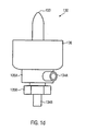
- Fig. 1 a schematically shows a cleaning system 100 in which a holder 110 is provided which is adapted to receive one or more milking cups 120 and to hold them in position during a cleaning sequence based on at least two different cleaning fluids.
- the holder 110 is provided in an illustrative embodiment in the form of a chamber in which, if necessary, a certain level of liquid, for example in the form of water, etc., can be maintained.
- the holder 110 is also advantageously designed such that the teat cups 120 can be received substantially with their entire volume, ie, over their entire length of travel, so that efficient rinsing and wetting of substantially all of the outer surface of the teat cups 120 is carried out if required can be, if necessary.
- the holder 110 may be formed such that at least the interior of the Melkbecher 120 is accessible for proper cleaning and disinfecting, without substantially the entire outer area of the teat cups 120 is enclosed by the holder 110.
- one or more fluid dispensing devices 130 are provided, which are configured and arranged such that at least a first cleaning fluid 131 and a second cleaning fluid 132, which are obtained from corresponding fluid sources 131a, 132a, can be dispensed. That is, the one or more dispensers 130 may introduce at least the two cleaning fluids 131, 132 into the teat cups 120, at least into a lower portion thereof. In this way, the milking cup 120 can be acted on at a single predetermined cleaning position with different cleaning fluids in a very space-saving manner.
- each of the dispensers 130 is provided with a respective outlet port 133 which may be connected to the fluid source 132a via a corresponding feed line 132b and associated valve 132c.
- the outlet port 133 can be connected to the fluid source 131a via a corresponding feed line 131b and a corresponding valve device 131c, wherein a corresponding introduction of the cleaning fluids 132, 131 can take place according to the requirements of the cleaning process.
- the efficiency for example, in view of the penetration depth of the respective cleaning liquid into the teat cup 120 can be suitably controlled by adjusting the pressure in the fluid sources 132a, 131a and / or the function of the valve means 132c, 131c and / or the size and shape the outlet port 133 are suitably selected.
- the outlet opening 133 may be provided in the form of a nozzle, wherein by adjusting the pressure conditions in the corresponding fluid sources 132a, 131a, a wetting of the inner surfaces of the milking cup 120 can be achieved.
- a suitable liquid level can be adjusted during certain operating phases in the holder 110, if desired.
- Fig. 1 b shows a schematic cross-sectional view of a portion of the output device 130, wherein one or more first outlet openings 133a and one or more second outlet openings 133b are provided, which communicate respectively via the respective valve means 132c, 131c with the corresponding fluid sources 131 a, 132 a.
- a mutual influence of the corresponding cleaning fluids can also be significantly reduced within the output device 133 if necessary.
- Fig. 1 c shows a schematic plan view of the dispensing device 133, wherein a plurality of first outlet openings 133a and a plurality of second outlet openings 133b are arranged so that a possible isotropic wetting of the teat cup 120 is given for both types of fluids. That is, in the illustrated embodiment, a first opening 133a and a second opening 133b are alternately provided adjacent to each other in the circumferential direction, so that a uniform discharge of the fluids 131, 132 is achieved.
- Fig. 1d 1 schematically shows a side view of the dispensing device 130 according to an embodiment in which corresponding connections 134a, 134b are provided in order to liquid-tightly connect the feeders 134a, 134b to the outlet opening 133 via corresponding screw connections 135a, 135b.
- the connection 134a with the screw connection 135a can establish a fluid-tight connection with a base body in which the outlet opening 133 and the corresponding channel are formed, which can reach the outlet opening 133 via suitably positioned inlet openings (not shown) in the base body.
- a pan or chamber 136 is provided, which may also advantageously hold a certain amount of cleaning fluid when continuous wetting of respective areas of the teat cup 120 is desired.
- the corresponding elements are mechanically connected to one another by screw connections and corresponding seals, so that, if required, the individual parts can be dismantled and, for example, cleaned.
- one or more of the described components may be provided as a unit, so that corresponding machining can be carried out inexpensively.
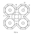
- Fig. 1e schematically shows a plan view of the cleaning system 100, with their output devices 130 are provided in the holder 110, so as to four, for example Melkbecher record simultaneously.
- a spraying device 140 is provided, in which one or more outlet openings 141 are connected to a corresponding source of cleaning agents, in order to thereby wet outer areas of the teat cups with the cleaning agent, for example water.
- the cleaning agent for example water.
- the teat cups 130 are brought to the holder 110, this being done automatically by means of a transport device, as explained in more detail below, or manually.
- the partially funnel-shaped design of the holding device 110 makes it possible to efficiently guide the milking cups 120 as soon as mechanical contact with the holder 110 has taken place.
- the teat cups 120 are substantially independently centered by the tapered shape of the holder 110 in the illustrated embodiments and guided to the appropriate cleaning positions.
- the cleaning position of the milking cups 120 is shown as leaving a distance to the bottom of the holder 110, while in other embodiments, the milking cups are lowered to the bottom of the holder 110.
- the dispenser 130 may be activated prior to reaching the final cleaning position to dispense a cleaning fluid.
- the cleaning position which is to be understood as a position in which the teat cups 120 are exposed to cleaning fluids by the dispenser 130, is changed during certain operating phases to allow for more efficient wetting.
- the height position of the teat cups 120 may be varied to allow varying depth of penetration of the cleaning fluids.
- a corresponding variable height position may be achieved by suitable means, such as a transport device as will be described later.
- the spraying device 140 (see FIG Fig. 1 e) be activated so as to achieve already an efficient cleaning on the outside of the teat cups 120 over an extended length range.
- the milking cups 120 are thus arranged so that at least part of the interior of the milking cups 120 can be wetted by means of the dispensing devices 130 with different cleaning fluids.
- a desired amount and type of cleaning fluid may be introduced via the dispenser 130.
- a corresponding automated sequence can be set in motion so that a predefined cleaning sequence takes place without manual access.
- both the duration of action and the amount of the cleaning fluid supplied can be efficiently controlled by means of the cleaning system 100, so that constant operating conditions are maintained over a plurality of cleaning processes, while maintaining appropriate regulations.
- a corresponding cleaning sequence comprising at least the aforementioned three steps may be performed in a time window of 30 to 60 seconds, but any other timings are possible as needed.
- a corresponding dynamic adaptation may also take place, for example if more intensive cleaning is required.
- the required disinfection between the individual milking processes can be achieved, for example, by feeding an amount of 0.1 to 0.5 liters of peracetic acid for each four milking cups 120, whereby the corresponding amount of used cleaning fluid can be removed after each individual cleaning process. as will be explained in more detail below, so that each individual cleaning operation can be carried out on the basis of a substantially uncontaminated, newly supplied cleaning fluid.
- a corresponding disinfection of the cleaning system 100 itself can be carried out if, for example, a corresponding cleaning liquid is held in the holder 110 without the presence of the milking cups 120, or if this is applied by means of the dispensing devices 130 and / or the spraying device 140, if provided when no milking cups 120 are positioned.
- a corresponding cleaning liquid is held in the holder 110 without the presence of the milking cups 120, or if this is applied by means of the dispensing devices 130 and / or the spraying device 140, if provided when no milking cups 120 are positioned.
- an active reduction in the amount of cleaning fluid (s) may be brought about after a desired exposure time, such as by mechanical movement of the teat cups 120, or the like, as described in more detail below.
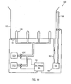
- Fig. 1f 12 schematically illustrates the cleaning system 100 according to another illustrative embodiment in which a controller 150 is provided operatively connected to the valve devices 132c, 131c to thereby control the supply of the respective cleaning fluid 132,131.
- the controller 150 may, in illustrative embodiments, have implemented a corresponding cleaning sequence such that in a timely coordinated manner, the respective fluid sources 132a, 131a are connected to the respective dispensers 130 so that a desired amount of corresponding cleaning fluid is supplied.
- the controller 150 may suitably adjust the exposure time of respective cleaning fluids, wherein in some illustrative embodiments, a predetermined exposure time is predetermined, while in other illustrative embodiments, one or more parameter values may be changed to dynamically determine the exposure time and / or amount to control the supplied cleaning fluids.
- the cleaning system 100 may have a corresponding sensor device (not shown) which outputs a signal as a function of the degree of contamination of the milking cup 120 positioned in the system 100, on the basis of which the exposure time and / or the amount is set.
- a selection of different cleaning programs may be implemented, which may then be selectively retrieved, for example by manual selection.
- a device 160 is also provided, with which a desired level of a cleaning fluid can be held in the holder 110, if this is designed in the form of a chamber or a trough.
- the device 160 may include a reservoir 161 into which used cleaning fluid is introduced via a respective drain line 162.
- the drain line 162 may be provided with a controllable valve device so that corresponding liquids can be drained off in a controlled manner. In this way, a suitable liquid level can be set, which can be maintained at a desired level by appropriate controlled discharge of liquid.
- the drain line 162 may be represented by an opening in the bracket 110, which opening may then be fluid-tightly sealed in the presence of a teat cup 120.
- a bleed line 163 may be provided with controllable valve means 163c to maintain the level in the fixture 110 at a desired level when needed, the valve means 163c being operable when in certain operating phases, such as a final cleaning higher liquid level is desired.
- the restriction device 160 may include other suitable means, such as a riser, etc., so that when a set height is exceeded, liquid drains into the reservoir 161.
- a sensor device for example in the form of a pressure sensor, may be present in order to obtain a signal as a function of the filling level in the holder 110, which can then be evaluated by the control device 150 in order to set the corresponding filling level, for example by the valve device 163c is controlled appropriately.
- a desired liquid level in the cleaning system 100 can be maintained, in which case when positioning the teat cups 120, the corresponding liquid with a corresponding amount of residual liquid, which exits the Melkbechem 120, can be discharged into the reservoir 161.
- the controller 150 may then initiate a suitable cleaning sequence, wherein, if necessary, the respective cleaning fluids may be maintained in the holder 110 by means of the means 160 having a desired liquid level.
- the beginning of a respective cleaning sequence may, in one illustrative embodiment, be determined based on a sensor device 151 which may supply a signal dependent on the positioning of the teat cups 120 to the controller 150, on the basis of which appropriate control activities may be initiated.
- the sensor device 151 may be a pressure-sensitive sensor device, so that the presence of a milking cup 120 can be detected.
- the sensor device 151 may be used for level detection within the fixture 110 when there is no teat cup 120.
- the sensor device 151 may be configured in any other suitable manner to detect the presence of a milking cup 120.
- the sensor device 151 may include a pressure switch that outputs a corresponding signal upon contact with the teat cup 120.
- proximity switches or other means may be provided to generate a signal dependent on the relative position of the milking cup 120 relative to the holder 110.
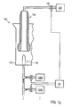
- Fig. 1g schematically shows the cleaning system 100 according to another illustrative embodiment.
- the control device 150 is provided in the form of a vacuum control device, so that an operating vacuum, which is generated by a vacuum source 181, is controllable in the milking cup 120 by the control device 150 by means of a valve device 152.
- the operating vacuum in the milking cup 120 may be activated and deactivated depending on the positioning of the milking cup 120.
- the controller 150 can then deactivate the vacuum, so that corresponding amounts of milk remaining can then flow off in a controlled manner and can thus be disposed of. Then, the further course of the cleaning process in the system 100 can proceed in a suitable manner, for example by means of the controller 150, in order to introduce one or more cleaning fluids into the teat cup 120 via the dispenser 130 in a suitable manner.
- Fig. 2a schematically shows a milking system 280, in which a vacuum source 281 is formed to provide a required for milking operating vacuum.
- the vacuum source 281 is further connected to a milk collecting device 282 and a corresponding milking harness 221, which in turn has a plurality of milking cups 220.
- a transport device 284 is provided in the milking installation 280, which is designed so that the milking equipment 211 can be moved after a milking operation in a suitable manner to a cleaning installation 200 in order to allow intermediate disinfection after individual milking operations.
- the cleaning system 200 is designed as described above in connection with the cleaning system 100 is.
- the cleaning system 200 is in particular designed to supply two or more different cleaning fluids by means of an output device associated with each milking cup 220, such as the dispensing device 130 as described above.
- a holding device 283 is further provided in the milking installation 280, which is designed so that the milking equipment 211, ie in particular the milking cups 220, are arranged so that they can be suitably applied manually to the udder of an animal.
- the holding device 283 may be designed so that during the operating phase for milking, ie during a milking process and during the application and removal of the individual milking cup 220, a substantially horizontal direction through the holding device 283 and thus a substantially horizontal position and Orientation of the milking cups 220 contained therein is defined.
- the holding device 283 may be configured to carry out the process of removing the milking cups 220 in an automated or semi-automated manner, for example by momentarily interrupting the operating vacuum upon the action of an operator so that the milking cups 220 fall off and are automatically retrieved by the holding device 283 can be.
- the process of removing the milking cups 220 may also be performed manually, with the holding device 283 allowing for individually removing the milking cups 220 and returning them to the holder 283.
- the transport device 284 can position the milking cluster 221 in a suitable manner above the cleaning system 200, in order to allow corresponding positioning of the milking cups 220 at the cleaning positions provided for this purpose.
- the transport device 284 may be designed so that the holding device 283 is arranged substantially vertically above the cleaning system 200 in order to enable insertion of the milking cups 220 into the corresponding holder 210 of the cleaning system 200.
- Fig. 2b schematically shows the milking system 280, wherein the holding device 283 is positioned vertically.
- a corresponding vacuum drive means for example in the form of the controller 150, or the like, is provided, so that at least during the positioning phase in which residual milk can flow out in an uncontrolled manner, the operating vacuum in the teat cup 220 is applied, so that substantially no contamination of the cleaning system 200 outside of the holder 210 is caused by residual milk.
- the operating vacuum again be deactivated so that the residual milk flows into the holder 210 controlled.
- the operating vacuum may continue to be applied until the teat cups 220 are positioned in the holder 210.
- the lowering of the teat cups 220 is already carried out with a cleaning agent, so that the corresponding outer sides of the teat cups 220 can be efficiently cleaned over the entire length or at least a substantial part thereof.
- the lowering of the teat cups 220 can be accomplished by means of the transport device 284 and / or the holding device 283, for example, by means of unrolling the supply hoses for the teat cups 220, then positioning them in the holder 210. Thereafter, a corresponding cleaning sequence can be carried out, as explained above.
- the height position of the teat cups can be varied as needed during the supply of one or more cleaning fluids for the wetting of the interior of the teat cups 220.
- the milking cups 220 are subjected to an active "dehumidification" process after one or more process steps to remove cleaning fluid from the milking cup 220.
- the transport means 284 is actuated to lift the milking cups 220 in the holder 210 and mechanically move them to accelerate the dripping of the liquid.
- an actuator 285 is provided in the transport device 284, which causes a suitable movement of the teat cups.
- the active "dehumidification" of the teat cups 220 may, for example, be done after each introduction of a fluid and after the desired exposure time, or is performed only after certain steps. A corresponding mechanical movement can be carried out for several seconds or longer if required. If corresponding deflections of the teat cups 220 are too large so that they can not be performed within the holder 210 in the raised state of the teat cups, the transport means 284 can approach a suitable "dry position" in which the required "freedom of movement" of the teat cups is given.
- a device for generating a gas flow for dehumidifying the milking cups 220 may be provided, so that preferably an outwardly directed flow is built up in the milking cup 220.
- a fluid source can be connected by suitable controllable valve devices with the interior of the milking cup via the corresponding milk lines.
- the milking harness 221 can then be used for another milking.
- the transport means 284 may move the holding means 283 into a suitable, i. bring substantially horizontal position so that the teat cups 220 are ready for docking.
- the cleaning system 200 can be used in different operating modes, as also explained above, so that, for example, a further cleaning of the milking harness 221 can be initiated if required, for example cleaning fluid can also be supplied through the connecting lines of the milking cups 220 into this can be introduced, which can then be discharged efficiently controlled in the cleaning system 200. Also, in such a cleaning phase, a high liquid level can be generated within the holder 210, so that an efficient cleaning of the outer sides of the teat cups 220 can be ensured.
- the operating vacuum can be activated and deactivated in a suitable manner, so as to enable efficient flushing of all fluid connections involved, in particular during a final cleaning.
- a control device for example the control device 150, may be provided in the cleaning system 200 in order to control appropriately controllable valve devices for connecting the teat cups to a rinsing liquid reservoir, so that cleaning liquid can flow through all fluid connections in a suitable manner.
Landscapes
- Life Sciences & Earth Sciences (AREA)
- Animal Husbandry (AREA)
- Environmental Sciences (AREA)
- Cleaning In General (AREA)
- Cleaning By Liquid Or Steam (AREA)
Abstract
Claims (15)
- Installation de nettoyage de gobelets trayeurs comprenant :un support pour recevoir au moins une partie d'un gobelet trayeur qui comporte une ouverture pour introduire un trayon, dans laquelle le support est agencé dans une chambre conformée pour maintenir un niveau de fluide donné au moins dans une phase de service prédéterminée,un dispositif de distribution de fluide conçu pour introduire dans l'ouverture un premier fluide de nettoyage provenant d'une première source de fluide et un deuxième fluide de nettoyage provenant d'une deuxième source de fluide, etun dispositif de contrôle de vide conçu pour commander une sous-pression de service dans le gobelet trayeur de manière à désactiver au moins temporairement la sous-pression après le positionnement du gobelet trayeur dans le support.
- Installation de nettoyage de gobelets trayeurs selon la revendication 1, dans laquelle un dispositif d'alimentation connecté au dispositif de distribution de fluide est pourvu d'une première conduite d'alimentation qui est connectée via un premier dispositif de vanne avec la première source de fluide et d'une deuxième conduite d'alimentation qui est connectée via un deuxième dispositif de vanne avec la deuxième source de fluide.
- Installation de nettoyage de gobelets trayeurs selon la revendication 1 ou 2, dans laquelle le dispositif de distribution de fluide comporte une ouverture de sortie qui peut être alimentée par les première et deuxième sources de fluide.
- Installation de nettoyage de gobelets trayeurs selon l'une des revendications 1 à 3, dans laquelle le dispositif de distribution de fluide comporte une première ouverture de sortie qui peut être alimentée par la première source de fluide et une deuxième ouverture de sortie qui peut être alimentée par la deuxième source de fluide.
- Installation de nettoyage de gobelets trayeurs selon l'une des revendications 1 à 4, comportant en outre un dispositif de commande conçu pour commander l'alimentation des premier et deuxième fluides de nettoyage vers le dispositif de distribution de fluide.
- Installation de nettoyage de gobelets trayeurs selon la revendication 5, dans laquelle le dispositif de commande est conçu pour commander l'alimentation successive et temporisée des premier et deuxième fluides de nettoyage.
- Installation de nettoyage de gobelets trayeurs selon la revendication 6, dans laquelle le dispositif de commande est conçu pour commander l'alimentation du premier fluide de nettoyage, ensuite l'alimentation du deuxième fluide de nettoyage, puis de nouveau l'alimentation du premier fluide de nettoyage.
- Installation de nettoyage de gobelets trayeurs selon l'une des revendications 5 à 7, dans laquelle le dispositif de commande est en outre conçu pour procurer une durée d'action prédéterminée pour le premier et/ou le deuxième fluide de nettoyage avant que l'alimentation de l'autre fluide de nettoyage ne soit commandée.
- Installation de nettoyage de gobelets trayeurs selon la revendication 1, dans laquelle un dispositif de limitation de niveau adapté pour limiter le niveau de fluide dans la chambre à un niveau maximal prédéterminé est pourvu.
- Installation de nettoyage de gobelets trayeurs selon l'une des revendications 1 à 9, comportant en outre un dispositif de déshumidification de fluide conçu pour réduire activement la proportion du premier et/ou du deuxième fluide dans le gobelet trayeur.
- Installation de nettoyage de gobelets trayeurs selon la revendication 10, dans laquelle le dispositif de déshumidification de fluide comporte un dispositif à actuateur conçu pour mettre en mouvement le gobelet trayeur après l'application du premier et/ou du deuxième fluide de nettoyage.
- Installation de traite comportant
une machine de traite à plusieurs gobelets trayeurs,
un dispositif de mise sous vide pour produire une sous-pression dans la machine de traite afin d'aspirer le lait,
une conduite de collecte de lait connectée à la machine de traite et au dispositif de mise sous vide, et
une installation de nettoyage de gobelets trayeurs selon l'une des revendications 1 à 11. - Installation de traite selon la revendication 12, comportant en outre un dispositif de retenue des gobelets trayeurs conçu pour positionner les gobelets trayeurs pour leur placement manuel lors de la procédure de traite.
- Installation de traite selon les revendications 12 et 13, dans laquelle le dispositif de transport est connecté au dispositif de retenue et conçu pour positionner le dispositif de retenue après une procédure de traite par rapport à l'installation de nettoyage de telle manière que les gobelets trayeurs sont placés dans le support de l'installation de nettoyage.
- Installation de traite selon la revendication 12, dans laquelle le dispositif de contrôle de vide maintient la sous-pression de service active jusqu'au positionnement des gobelets trayeurs dans le support.
Applications Claiming Priority (2)
| Application Number | Priority Date | Filing Date | Title |
|---|---|---|---|
| DE102006053602A DE102006053602A1 (de) | 2006-11-14 | 2006-11-14 | Reinigungsanlage für Melkbecher |
| PCT/EP2007/009842 WO2008058723A1 (fr) | 2006-11-14 | 2007-11-14 | Système de nettoyage pour gobelet trayeur |
Publications (2)
| Publication Number | Publication Date |
|---|---|
| EP2101562A1 EP2101562A1 (fr) | 2009-09-23 |
| EP2101562B1 true EP2101562B1 (fr) | 2012-07-25 |
Family
ID=39203310
Family Applications (1)
| Application Number | Title | Priority Date | Filing Date |
|---|---|---|---|
| EP07846588A Active EP2101562B1 (fr) | 2006-11-14 | 2007-11-14 | Système de nettoyage pour gobelet trayeur |
Country Status (5)
| Country | Link |
|---|---|
| US (2) | US9380758B2 (fr) |
| EP (1) | EP2101562B1 (fr) |
| DE (1) | DE102006053602A1 (fr) |
| ES (1) | ES2389632T3 (fr) |
| WO (1) | WO2008058723A1 (fr) |
Families Citing this family (33)
| Publication number | Priority date | Publication date | Assignee | Title |
|---|---|---|---|---|
| DE102006053602A1 (de) * | 2006-11-14 | 2008-05-15 | Jakob Maier | Reinigungsanlage für Melkbecher |
| DE102008056545A1 (de) * | 2008-11-10 | 2010-05-27 | Gea Westfaliasurge Gmbh | Reinigungseinheit zum Reinigen wenigstens eines Kopfabschnittes eines Melkbechers |
| DE102008056543A1 (de) | 2008-11-10 | 2010-05-27 | Gea Westfaliasurge Gmbh | Melkbecher-Reinigungseinheit mit einer Verteilereinheit |
| NL1037523C2 (nl) | 2009-12-02 | 2011-06-06 | Lely Patent Nv | Melkinrichting, en werkwijze voor reinigen daarvan. |
| US9161511B2 (en) | 2010-07-06 | 2015-10-20 | Technologies Holdings Corp. | Automated rotary milking system |
| US8800487B2 (en) | 2010-08-31 | 2014-08-12 | Technologies Holdings Corp. | System and method for controlling the position of a robot carriage based on the position of a milking stall of an adjacent rotary milking platform |
| US9149018B2 (en) | 2010-08-31 | 2015-10-06 | Technologies Holdings Corp. | System and method for determining whether to operate a robot in conjunction with a rotary milking platform based on detection of a milking claw |
| US8720382B2 (en) | 2010-08-31 | 2014-05-13 | Technologies Holdings Corp. | Vision system for facilitating the automated application of disinfectant to the teats of dairy livestock |
| US10111401B2 (en) | 2010-08-31 | 2018-10-30 | Technologies Holdings Corp. | System and method for determining whether to operate a robot in conjunction with a rotary parlor |
| EP2632247B1 (fr) | 2010-10-26 | 2017-04-26 | DeLaval Holding AB | Système de commande et procédé de traite d'éléments dans une salle de traite |
| US8746176B2 (en) | 2011-04-28 | 2014-06-10 | Technologies Holdings Corp. | System and method of attaching a cup to a dairy animal according to a sequence |
| US9357744B2 (en) | 2011-04-28 | 2016-06-07 | Technologies Holdings Corp. | Cleaning system for a milking box stall |
| US9681634B2 (en) | 2011-04-28 | 2017-06-20 | Technologies Holdings Corp. | System and method to determine a teat position using edge detection in rear images of a livestock from two cameras |
| US9058657B2 (en) | 2011-04-28 | 2015-06-16 | Technologies Holdings Corp. | System and method for filtering data captured by a 3D camera |
| US8671885B2 (en) | 2011-04-28 | 2014-03-18 | Technologies Holdings Corp. | Vision system for robotic attacher |
| US9265227B2 (en) | 2011-04-28 | 2016-02-23 | Technologies Holdings Corp. | System and method for improved attachment of a cup to a dairy animal |
| US9215861B2 (en) | 2011-04-28 | 2015-12-22 | Technologies Holdings Corp. | Milking box with robotic attacher and backplane for tracking movements of a dairy animal |
| US9043988B2 (en) | 2011-04-28 | 2015-06-02 | Technologies Holdings Corp. | Milking box with storage area for teat cups |
| US9258975B2 (en) | 2011-04-28 | 2016-02-16 | Technologies Holdings Corp. | Milking box with robotic attacher and vision system |
| US10127446B2 (en) | 2011-04-28 | 2018-11-13 | Technologies Holdings Corp. | System and method for filtering data captured by a 2D camera |
| US8683946B2 (en) | 2011-04-28 | 2014-04-01 | Technologies Holdings Corp. | System and method of attaching cups to a dairy animal |
| US9107379B2 (en) | 2011-04-28 | 2015-08-18 | Technologies Holdings Corp. | Arrangement of milking box stalls |
| US9161512B2 (en) | 2011-04-28 | 2015-10-20 | Technologies Holdings Corp. | Milking box with robotic attacher comprising an arm that pivots, rotates, and grips |
| US9107378B2 (en) | 2011-04-28 | 2015-08-18 | Technologies Holdings Corp. | Milking box with robotic attacher |
| US9049843B2 (en) | 2011-04-28 | 2015-06-09 | Technologies Holdings Corp. | Milking box with a robotic attacher having a three-dimensional range of motion |
| US8885891B2 (en) | 2011-04-28 | 2014-11-11 | Technologies Holdings Corp. | System and method for analyzing data captured by a three-dimensional camera |
| DK3202255T3 (da) * | 2011-04-28 | 2020-07-06 | Technologies Holdings Corp | Malkeboks med rensesystem |
| US8903129B2 (en) | 2011-04-28 | 2014-12-02 | Technologies Holdings Corp. | System and method for filtering data captured by a 2D camera |
| DE102012110501A1 (de) * | 2012-03-14 | 2013-09-19 | Gea Farm Technologies Gmbh | Platzteiler einer Melkstandanordnung und Melkstandanordnung |
| JP6540705B2 (ja) * | 2013-12-19 | 2019-07-10 | ジーイー・ヘルスケア・バイオサイエンス・アクチボラグ | 生物学的液体処理システムのための遠隔操作弁 |
| GB201405611D0 (en) * | 2014-03-28 | 2014-05-14 | An Udder Ip Company Ltd | A teat cup |
| FR3095139B1 (fr) * | 2019-04-19 | 2021-10-08 | Auum | Dispositif de nettoyage d’un objet |
| PL240218B1 (pl) * | 2019-09-27 | 2022-02-28 | Maciej Dyrka | Układ myjący oraz sposób mycia zwłaszcza aparatu udojowego |
Family Cites Families (26)
| Publication number | Priority date | Publication date | Assignee | Title |
|---|---|---|---|---|
| US1946400A (en) * | 1931-10-29 | 1934-02-06 | Laval Separator Co De | Device for cleaning teat cups |
| US2595539A (en) * | 1948-04-17 | 1952-05-06 | Hall Lab Inc | Valveless vacuum-operated fluid circulating device for cleaning hollow objects such as teat cups and milk tubes |
| US3629005A (en) * | 1968-08-19 | 1971-12-21 | Dallas J B Belden | Milking unit sanitizer |
| US3688783A (en) * | 1970-08-17 | 1972-09-05 | William E Owens | Sanitizing apparatus |
| US3834407A (en) * | 1973-05-14 | 1974-09-10 | Laval Separator Co De | Milking unit washer |
| US4175514A (en) | 1977-05-19 | 1979-11-27 | Frank F. Souza, Inc. | Automatic milking machine control and cleansing |
| DE3322226C1 (de) * | 1983-06-21 | 1985-01-03 | Westfalia Separator Ag, 4740 Oelde | Vorrichtung zur automatischen Spuelung von Melkeimern |
| US4572105A (en) * | 1984-09-20 | 1986-02-25 | Alfa-Laval, Inc. | Backflushing system |
| NL8502434A (nl) * | 1985-09-04 | 1987-04-01 | Multinorm Bv | Melkinrichting. |
| NL8700249A (nl) * | 1987-02-02 | 1988-09-01 | Multinorm Bv | Werkwijze voor het reinigen van een tepel van een vrouwelijk dier, melkwerkwijze en beker ten gebruike bij bovengenoemde werkwijzen. |
| US4854336A (en) * | 1988-07-29 | 1989-08-08 | Martin Byzitter | Teat cup disinfectant system |
| GB8926950D0 (en) * | 1989-11-29 | 1990-01-17 | Ambic Equip Ltd | Automatic milking apparatus |
| EP0459817B1 (fr) * | 1990-06-01 | 1994-06-22 | Btg International Limited | Machine à traire automatique |
| NL9200258A (nl) * | 1991-10-04 | 1993-05-03 | Lely Nv C Van Der | Werkwijze voor het reinigen van melkbekers en/of het nabehandelen van de spenen van een gemolken dier, inrichting voor het melken van dieren voor het toepassen van deze werkwijze(n), en spoelwerktuig toegepast in een dergelijke inrichting. |
| DE4432754C2 (de) * | 1994-09-14 | 1997-02-20 | Laub Maier Maria | Vorrichtungen und Verfahren zum Reinigen von Melkbechern |
| NL1004196C1 (nl) * | 1995-11-24 | 1997-05-27 | Maasland Nv | Inrichting voor het melken van dieren. |
| NL1004921C2 (nl) * | 1996-12-31 | 1998-07-01 | Prolion Bv | Inrichting en werkwijze voor het melken van dieren. |
| NL1007727C2 (nl) * | 1997-12-08 | 1999-06-09 | Maasland Nv | Spoelvloeistofreinigingsinrichting voor het reinigen van althans een deel van een melkmachine. |
| SE515443C3 (sv) * | 1999-12-15 | 2001-08-14 | Delaval Holding Ab | Förfarande och anordning för spenkoppstvättning |
| SE0202988D0 (sv) | 2002-03-15 | 2002-10-10 | Delaval Holding Ab | A method and an arrangement at a dairy farm |
| US6910444B1 (en) * | 2003-03-21 | 2005-06-28 | John Soppe | Heated milk supply system for livestock |
| GB0408968D0 (en) * | 2004-04-22 | 2004-05-26 | Duke James R J | Milking equipment |
| DE102004033637B4 (de) * | 2004-03-23 | 2012-07-26 | Wilfried Hatzack | Haltevorrichtung für Melkbecher mit einem Antrieb zur Erzeugung einer Bewegung |
| NL1025818C2 (nl) * | 2004-03-26 | 2005-10-03 | Lely Entpr Ag | Inrichting en werkwijze voor het melken van een melkdier. |
| SE0500043D0 (sv) * | 2005-01-10 | 2005-01-10 | Delaval Holding Ab | A milking arrangement |
| DE102006053602A1 (de) * | 2006-11-14 | 2008-05-15 | Jakob Maier | Reinigungsanlage für Melkbecher |
-
2006
- 2006-11-14 DE DE102006053602A patent/DE102006053602A1/de not_active Withdrawn
-
2007
- 2007-11-14 US US12/312,531 patent/US9380758B2/en active Active
- 2007-11-14 WO PCT/EP2007/009842 patent/WO2008058723A1/fr active Application Filing
- 2007-11-14 ES ES07846588T patent/ES2389632T3/es active Active
- 2007-11-14 EP EP07846588A patent/EP2101562B1/fr active Active
-
2015
- 2015-08-10 US US14/822,344 patent/US9801352B2/en active Active
Also Published As
| Publication number | Publication date |
|---|---|
| US9380758B2 (en) | 2016-07-05 |
| US20110155068A1 (en) | 2011-06-30 |
| US20150342142A1 (en) | 2015-12-03 |
| WO2008058723A1 (fr) | 2008-05-22 |
| ES2389632T3 (es) | 2012-10-29 |
| DE102006053602A1 (de) | 2008-05-15 |
| US9801352B2 (en) | 2017-10-31 |
| EP2101562A1 (fr) | 2009-09-23 |
Similar Documents
| Publication | Publication Date | Title |
|---|---|---|
| EP2101562B1 (fr) | Système de nettoyage pour gobelet trayeur | |
| DE60011114T2 (de) | Verfahren und vorrichtung zum reinigen der zitzen eines tieres | |
| DE60013892T2 (de) | Verfahren und vorrichtung zur reinigung von zitzenbechern | |
| DE3687351T2 (de) | Geraet zum automatischen melken von tieren. | |
| DE69819772T2 (de) | Kombinierte reinigungs und vormilkungs vorrichtung | |
| DE69809394T2 (de) | Reinigungsvorrichtung zum reinigen mindestens eines teils eines melkgeräts mit einer spüllösung | |
| DE2947576A1 (de) | Verfahren und vorrichtung zum abreinigen eines endoskopes | |
| DE69231748T2 (de) | Melkvorrichtung und Zitzenbecher für diese Vorrichtung | |
| DE602005004684T3 (de) | Verfahren zum Melken eines Milchtieres | |
| EP1222853A2 (fr) | Procédé et dispositif de traite | |
| DE60211762T2 (de) | Reinigungsvorrichtung zum Reinigen des Äußeren eines Melkstandes | |
| DE102014113161A1 (de) | Getränkeautomat zur Zubereitung von Aufgussgetränken und Verfahren zur Erzeugung eines Pflegegemisches zur Pflege des Strömungsleitungssystems eines derartigen Getränkeautomaten | |
| EP1065925B1 (fr) | Procede pour distribuer a des animaux des aliments et/ou des produits nettoyants contenus dans un recipient de melange | |
| EP2892324B2 (fr) | Installation de nettoyage automatique de nettoyage/traitement de trayons d'un animal laitier | |
| DE602004008277T2 (de) | Melkvorrichtung und verfahren zum umgang mit einer melkvorrichtung | |
| DE4339131A1 (de) | Verfahren und Vorrichtung für eine Leistungssteigerung und Verbesserung bei der Gewinnung von Kuhmilch | |
| EP2108253B1 (fr) | Procédé de nettoyage d'une installation de traite | |
| DE4244753A1 (de) | Vorrichtung zum Reinigen und/oder Desinfizieren und/oder Pflegen von ärztlichen oder zahnärztlichen Bearbeitungsinstrumenten, insbesondere Handstücken | |
| DE2623499A1 (de) | Verfahren zum entzug von milch | |
| DE10316585A1 (de) | Verfahren zum Reinigen der milchführenden Teile einer Melkvorrichtung sowie Melkvorrichtung mit einer Einrichtung zum Reinigen der milchführenden Teile | |
| DE202017000895U1 (de) | Melkvorrichtung zum Melken von milchgebenden Tieren mit Spülfunktion | |
| DE102006038484A1 (de) | Verfahren und Vorrichtung zum Desinfizieren von Melkzeug | |
| EP1912492A1 (fr) | Salle de traite et procede de traite | |
| DE60218507T2 (de) | Verfahren zur Sanierung von Wasserleitungen zahnärtztlicher Einheiten und zahnärtztliche Einheit zur Durchführung dieses Verfahrens | |
| DE102021006390A1 (de) | Melkvorrichtung mit einer Reinigungseinrichtung |
Legal Events
| Date | Code | Title | Description |
|---|---|---|---|
| PUAI | Public reference made under article 153(3) epc to a published international application that has entered the european phase |
Free format text: ORIGINAL CODE: 0009012 |
|
| 17P | Request for examination filed |
Effective date: 20090610 |
|
| AK | Designated contracting states |
Kind code of ref document: A1 Designated state(s): AT BE BG CH CY CZ DE DK EE ES FI FR GB GR HU IE IS IT LI LT LU LV MC MT NL PL PT RO SE SI SK TR |
|
| DAX | Request for extension of the european patent (deleted) | ||
| GRAP | Despatch of communication of intention to grant a patent |
Free format text: ORIGINAL CODE: EPIDOSNIGR1 |
|
| GRAS | Grant fee paid |
Free format text: ORIGINAL CODE: EPIDOSNIGR3 |
|
| GRAA | (expected) grant |
Free format text: ORIGINAL CODE: 0009210 |
|
| AK | Designated contracting states |
Kind code of ref document: B1 Designated state(s): AT BE BG CH CY CZ DE DK EE ES FI FR GB GR HU IE IS IT LI LT LU LV MC MT NL PL PT RO SE SI SK TR |
|
| REG | Reference to a national code |
Ref country code: GB Ref legal event code: FG4D Free format text: NOT ENGLISH |
|
| REG | Reference to a national code |
Ref country code: DE Ref legal event code: R082 Ref document number: 502007010276 Country of ref document: DE Representative=s name: GRUENECKER, KINKELDEY, STOCKMAIR & SCHWANHAEUS, DE Ref country code: DE Ref legal event code: R082 Ref document number: 502007010276 Country of ref document: DE Representative=s name: GRUENECKER PATENT- UND RECHTSANWAELTE PARTG MB, DE |
|
| REG | Reference to a national code |
Ref country code: CH Ref legal event code: EP Ref country code: CH Ref legal event code: NV Representative=s name: BOVARD AG |
|
| REG | Reference to a national code |
Ref country code: NL Ref legal event code: T3 Ref country code: IE Ref legal event code: FG4D Free format text: LANGUAGE OF EP DOCUMENT: GERMAN Ref country code: AT Ref legal event code: REF Ref document number: 567335 Country of ref document: AT Kind code of ref document: T Effective date: 20120815 |
|
| REG | Reference to a national code |
Ref country code: SE Ref legal event code: TRGR |
|
| REG | Reference to a national code |
Ref country code: DE Ref legal event code: R096 Ref document number: 502007010276 Country of ref document: DE Effective date: 20120920 |
|
| REG | Reference to a national code |
Ref country code: ES Ref legal event code: FG2A Ref document number: 2389632 Country of ref document: ES Kind code of ref document: T3 Effective date: 20121029 |
|
| REG | Reference to a national code |
Ref country code: LT Ref legal event code: MG4D Effective date: 20120725 |
|
| PG25 | Lapsed in a contracting state [announced via postgrant information from national office to epo] |
Ref country code: IS Free format text: LAPSE BECAUSE OF FAILURE TO SUBMIT A TRANSLATION OF THE DESCRIPTION OR TO PAY THE FEE WITHIN THE PRESCRIBED TIME-LIMIT Effective date: 20121125 Ref country code: FI Free format text: LAPSE BECAUSE OF FAILURE TO SUBMIT A TRANSLATION OF THE DESCRIPTION OR TO PAY THE FEE WITHIN THE PRESCRIBED TIME-LIMIT Effective date: 20120725 Ref country code: CY Free format text: LAPSE BECAUSE OF FAILURE TO SUBMIT A TRANSLATION OF THE DESCRIPTION OR TO PAY THE FEE WITHIN THE PRESCRIBED TIME-LIMIT Effective date: 20120725 Ref country code: LT Free format text: LAPSE BECAUSE OF FAILURE TO SUBMIT A TRANSLATION OF THE DESCRIPTION OR TO PAY THE FEE WITHIN THE PRESCRIBED TIME-LIMIT Effective date: 20120725 |
|
| PG25 | Lapsed in a contracting state [announced via postgrant information from national office to epo] |
Ref country code: PL Free format text: LAPSE BECAUSE OF FAILURE TO SUBMIT A TRANSLATION OF THE DESCRIPTION OR TO PAY THE FEE WITHIN THE PRESCRIBED TIME-LIMIT Effective date: 20120725 Ref country code: PT Free format text: LAPSE BECAUSE OF FAILURE TO SUBMIT A TRANSLATION OF THE DESCRIPTION OR TO PAY THE FEE WITHIN THE PRESCRIBED TIME-LIMIT Effective date: 20121126 Ref country code: GR Free format text: LAPSE BECAUSE OF FAILURE TO SUBMIT A TRANSLATION OF THE DESCRIPTION OR TO PAY THE FEE WITHIN THE PRESCRIBED TIME-LIMIT Effective date: 20121026 Ref country code: LV Free format text: LAPSE BECAUSE OF FAILURE TO SUBMIT A TRANSLATION OF THE DESCRIPTION OR TO PAY THE FEE WITHIN THE PRESCRIBED TIME-LIMIT Effective date: 20120725 Ref country code: SI Free format text: LAPSE BECAUSE OF FAILURE TO SUBMIT A TRANSLATION OF THE DESCRIPTION OR TO PAY THE FEE WITHIN THE PRESCRIBED TIME-LIMIT Effective date: 20120725 |
|
| PG25 | Lapsed in a contracting state [announced via postgrant information from national office to epo] |
Ref country code: CZ Free format text: LAPSE BECAUSE OF FAILURE TO SUBMIT A TRANSLATION OF THE DESCRIPTION OR TO PAY THE FEE WITHIN THE PRESCRIBED TIME-LIMIT Effective date: 20120725 Ref country code: EE Free format text: LAPSE BECAUSE OF FAILURE TO SUBMIT A TRANSLATION OF THE DESCRIPTION OR TO PAY THE FEE WITHIN THE PRESCRIBED TIME-LIMIT Effective date: 20120725 Ref country code: RO Free format text: LAPSE BECAUSE OF FAILURE TO SUBMIT A TRANSLATION OF THE DESCRIPTION OR TO PAY THE FEE WITHIN THE PRESCRIBED TIME-LIMIT Effective date: 20120725 Ref country code: DK Free format text: LAPSE BECAUSE OF FAILURE TO SUBMIT A TRANSLATION OF THE DESCRIPTION OR TO PAY THE FEE WITHIN THE PRESCRIBED TIME-LIMIT Effective date: 20120725 |
|
| BERE | Be: lapsed |
Owner name: HATZACK, WILFRIED Effective date: 20121130 Owner name: MAIER, JAKOB Effective date: 20121130 |
|
| PG25 | Lapsed in a contracting state [announced via postgrant information from national office to epo] |
Ref country code: SK Free format text: LAPSE BECAUSE OF FAILURE TO SUBMIT A TRANSLATION OF THE DESCRIPTION OR TO PAY THE FEE WITHIN THE PRESCRIBED TIME-LIMIT Effective date: 20120725 |
|
| PLBE | No opposition filed within time limit |
Free format text: ORIGINAL CODE: 0009261 |
|
| STAA | Information on the status of an ep patent application or granted ep patent |
Free format text: STATUS: NO OPPOSITION FILED WITHIN TIME LIMIT |
|
| 26N | No opposition filed |
Effective date: 20130426 |
|
| PG25 | Lapsed in a contracting state [announced via postgrant information from national office to epo] |
Ref country code: BG Free format text: LAPSE BECAUSE OF FAILURE TO SUBMIT A TRANSLATION OF THE DESCRIPTION OR TO PAY THE FEE WITHIN THE PRESCRIBED TIME-LIMIT Effective date: 20121025 |
|
| REG | Reference to a national code |
Ref country code: IE Ref legal event code: MM4A |
|
| REG | Reference to a national code |
Ref country code: DE Ref legal event code: R097 Ref document number: 502007010276 Country of ref document: DE Effective date: 20130426 |
|
| PG25 | Lapsed in a contracting state [announced via postgrant information from national office to epo] |
Ref country code: BE Free format text: LAPSE BECAUSE OF NON-PAYMENT OF DUE FEES Effective date: 20121130 |
|
| PG25 | Lapsed in a contracting state [announced via postgrant information from national office to epo] |
Ref country code: IE Free format text: LAPSE BECAUSE OF NON-PAYMENT OF DUE FEES Effective date: 20121114 |
|
| PG25 | Lapsed in a contracting state [announced via postgrant information from national office to epo] |
Ref country code: MT Free format text: LAPSE BECAUSE OF FAILURE TO SUBMIT A TRANSLATION OF THE DESCRIPTION OR TO PAY THE FEE WITHIN THE PRESCRIBED TIME-LIMIT Effective date: 20120725 |
|
| REG | Reference to a national code |
Ref country code: AT Ref legal event code: MM01 Ref document number: 567335 Country of ref document: AT Kind code of ref document: T Effective date: 20121130 |
|
| PG25 | Lapsed in a contracting state [announced via postgrant information from national office to epo] |
Ref country code: AT Free format text: LAPSE BECAUSE OF NON-PAYMENT OF DUE FEES Effective date: 20121130 |
|
| PG25 | Lapsed in a contracting state [announced via postgrant information from national office to epo] |
Ref country code: TR Free format text: LAPSE BECAUSE OF FAILURE TO SUBMIT A TRANSLATION OF THE DESCRIPTION OR TO PAY THE FEE WITHIN THE PRESCRIBED TIME-LIMIT Effective date: 20120725 Ref country code: MC Free format text: LAPSE BECAUSE OF NON-PAYMENT OF DUE FEES Effective date: 20121130 |
|
| PG25 | Lapsed in a contracting state [announced via postgrant information from national office to epo] |
Ref country code: LU Free format text: LAPSE BECAUSE OF NON-PAYMENT OF DUE FEES Effective date: 20121114 |
|
| PG25 | Lapsed in a contracting state [announced via postgrant information from national office to epo] |
Ref country code: HU Free format text: LAPSE BECAUSE OF FAILURE TO SUBMIT A TRANSLATION OF THE DESCRIPTION OR TO PAY THE FEE WITHIN THE PRESCRIBED TIME-LIMIT Effective date: 20071114 |
|
| REG | Reference to a national code |
Ref country code: FR Ref legal event code: PLFP Year of fee payment: 9 |
|
| REG | Reference to a national code |
Ref country code: FR Ref legal event code: PLFP Year of fee payment: 10 |
|
| REG | Reference to a national code |
Ref country code: FR Ref legal event code: PLFP Year of fee payment: 11 |
|
| PGFP | Annual fee paid to national office [announced via postgrant information from national office to epo] |
Ref country code: GB Payment date: 20211126 Year of fee payment: 15 |
|
| PGFP | Annual fee paid to national office [announced via postgrant information from national office to epo] |
Ref country code: CH Payment date: 20211126 Year of fee payment: 15 |
|
| REG | Reference to a national code |
Ref country code: CH Ref legal event code: PL |
|
| GBPC | Gb: european patent ceased through non-payment of renewal fee |
Effective date: 20221114 |
|
| PG25 | Lapsed in a contracting state [announced via postgrant information from national office to epo] |
Ref country code: LI Free format text: LAPSE BECAUSE OF NON-PAYMENT OF DUE FEES Effective date: 20221130 Ref country code: CH Free format text: LAPSE BECAUSE OF NON-PAYMENT OF DUE FEES Effective date: 20221130 |
|
| PG25 | Lapsed in a contracting state [announced via postgrant information from national office to epo] |
Ref country code: GB Free format text: LAPSE BECAUSE OF NON-PAYMENT OF DUE FEES Effective date: 20221114 |
|
| PGFP | Annual fee paid to national office [announced via postgrant information from national office to epo] |
Ref country code: NL Payment date: 20231127 Year of fee payment: 17 |
|
| PGFP | Annual fee paid to national office [announced via postgrant information from national office to epo] |
Ref country code: ES Payment date: 20231201 Year of fee payment: 17 |
|
| PGFP | Annual fee paid to national office [announced via postgrant information from national office to epo] |
Ref country code: SE Payment date: 20231124 Year of fee payment: 17 Ref country code: IT Payment date: 20231129 Year of fee payment: 17 Ref country code: FR Payment date: 20231124 Year of fee payment: 17 Ref country code: DE Payment date: 20231129 Year of fee payment: 17 |