EP2101562B1 - Cleaning system for milking cups - Google Patents
Cleaning system for milking cups Download PDFInfo
- Publication number
- EP2101562B1 EP2101562B1 EP07846588A EP07846588A EP2101562B1 EP 2101562 B1 EP2101562 B1 EP 2101562B1 EP 07846588 A EP07846588 A EP 07846588A EP 07846588 A EP07846588 A EP 07846588A EP 2101562 B1 EP2101562 B1 EP 2101562B1
- Authority
- EP
- European Patent Office
- Prior art keywords
- milking
- cleaning
- fluid
- cleaning system
- cups
- Prior art date
- Legal status (The legal status is an assumption and is not a legal conclusion. Google has not performed a legal analysis and makes no representation as to the accuracy of the status listed.)
- Active
Links
- 238000004140 cleaning Methods 0.000 title claims abstract description 245
- 239000012530 fluid Substances 0.000 claims abstract description 153
- 238000000034 method Methods 0.000 claims abstract description 57
- 230000008569 process Effects 0.000 claims abstract description 49
- 235000013336 milk Nutrition 0.000 claims description 43
- 239000008267 milk Substances 0.000 claims description 43
- 210000004080 milk Anatomy 0.000 claims description 43
- 235000013365 dairy product Nutrition 0.000 claims description 8
- 238000013461 design Methods 0.000 claims description 5
- 238000007791 dehumidification Methods 0.000 claims description 4
- 238000004659 sterilization and disinfection Methods 0.000 abstract description 18
- 210000002445 nipple Anatomy 0.000 description 82
- 239000007788 liquid Substances 0.000 description 27
- KFSLWBXXFJQRDL-UHFFFAOYSA-N Peracetic acid Chemical compound CC(=O)OO KFSLWBXXFJQRDL-UHFFFAOYSA-N 0.000 description 20
- XLYOFNOQVPJJNP-UHFFFAOYSA-N water Substances O XLYOFNOQVPJJNP-UHFFFAOYSA-N 0.000 description 15
- 238000009736 wetting Methods 0.000 description 13
- 241001465754 Metazoa Species 0.000 description 12
- 230000000249 desinfective effect Effects 0.000 description 11
- 238000011109 contamination Methods 0.000 description 10
- 230000033001 locomotion Effects 0.000 description 10
- 239000000645 desinfectant Substances 0.000 description 7
- 239000012459 cleaning agent Substances 0.000 description 6
- 238000005507 spraying Methods 0.000 description 6
- 230000009471 action Effects 0.000 description 5
- 239000007789 gas Substances 0.000 description 4
- 238000009434 installation Methods 0.000 description 4
- 230000007774 longterm Effects 0.000 description 4
- 238000013459 approach Methods 0.000 description 3
- 210000000481 breast Anatomy 0.000 description 3
- 230000001419 dependent effect Effects 0.000 description 3
- 230000000694 effects Effects 0.000 description 3
- 230000036541 health Effects 0.000 description 3
- 230000035515 penetration Effects 0.000 description 3
- IJGRMHOSHXDMSA-UHFFFAOYSA-N Atomic nitrogen Chemical compound N#N IJGRMHOSHXDMSA-UHFFFAOYSA-N 0.000 description 2
- 230000008901 benefit Effects 0.000 description 2
- 230000009849 deactivation Effects 0.000 description 2
- 238000011010 flushing procedure Methods 0.000 description 2
- 230000006872 improvement Effects 0.000 description 2
- 238000012423 maintenance Methods 0.000 description 2
- 239000000203 mixture Substances 0.000 description 2
- 230000004044 response Effects 0.000 description 2
- 230000004913 activation Effects 0.000 description 1
- 230000006978 adaptation Effects 0.000 description 1
- 230000001580 bacterial effect Effects 0.000 description 1
- 244000052616 bacterial pathogen Species 0.000 description 1
- 244000309466 calf Species 0.000 description 1
- 239000000356 contaminant Substances 0.000 description 1
- 238000001514 detection method Methods 0.000 description 1
- 239000003599 detergent Substances 0.000 description 1
- 238000007599 discharging Methods 0.000 description 1
- 230000002349 favourable effect Effects 0.000 description 1
- 239000012535 impurity Substances 0.000 description 1
- 238000002347 injection Methods 0.000 description 1
- 239000007924 injection Substances 0.000 description 1
- 238000003780 insertion Methods 0.000 description 1
- 230000037431 insertion Effects 0.000 description 1
- 230000002045 lasting effect Effects 0.000 description 1
- 230000005923 long-lasting effect Effects 0.000 description 1
- 238000003754 machining Methods 0.000 description 1
- 238000004519 manufacturing process Methods 0.000 description 1
- 230000007246 mechanism Effects 0.000 description 1
- 238000003032 molecular docking Methods 0.000 description 1
- 229910052757 nitrogen Inorganic materials 0.000 description 1
- 230000006911 nucleation Effects 0.000 description 1
- 238000010899 nucleation Methods 0.000 description 1
- 230000004962 physiological condition Effects 0.000 description 1
- 230000009467 reduction Effects 0.000 description 1
- 239000000243 solution Substances 0.000 description 1
- 230000000638 stimulation Effects 0.000 description 1
- 239000000126 substance Substances 0.000 description 1
Images


Classifications
-
- A—HUMAN NECESSITIES
- A01—AGRICULTURE; FORESTRY; ANIMAL HUSBANDRY; HUNTING; TRAPPING; FISHING
- A01J—MANUFACTURE OF DAIRY PRODUCTS
- A01J7/00—Accessories for milking machines or devices
- A01J7/02—Accessories for milking machines or devices for cleaning or sanitising milking machines or devices
- A01J7/025—Teat cup cleaning, e.g. by rinse jetters or nozzles
-
- A—HUMAN NECESSITIES
- A01—AGRICULTURE; FORESTRY; ANIMAL HUSBANDRY; HUNTING; TRAPPING; FISHING
- A01J—MANUFACTURE OF DAIRY PRODUCTS
- A01J7/00—Accessories for milking machines or devices
- A01J7/02—Accessories for milking machines or devices for cleaning or sanitising milking machines or devices
-
- B—PERFORMING OPERATIONS; TRANSPORTING
- B08—CLEANING
- B08B—CLEANING IN GENERAL; PREVENTION OF FOULING IN GENERAL
- B08B3/00—Cleaning by methods involving the use or presence of liquid or steam
- B08B3/04—Cleaning involving contact with liquid
Definitions
- the present invention relates to the milking of dairy animals using a milking cluster with a plurality of milking cups, wherein in particular a cleaning or disinfection of the milking cups between the individual milking operations is carried out.
- Such cleaning systems are for example off WO 03/077645 known.
- the milking process itself usually takes place in such a way that, by generating a certain negative pressure in a milking cup, a milk flow from the teat into the milking cup is set in motion, from where the milked milk is then discharged into a corresponding collecting line. Since the introduction of automatic and semi-automatic milking systems in agricultural operations, much effort has been expended to ensure the most efficient operation of milking systems, as it is extremely important for a long-term high yield, a milking the natural suckling process of the calf on the mother's udder mimicking to run the automatic milking system.
- a lasting udder health can be achieved, which in turn is the prerequisite for achieving a long-term high yield and high quality of the milk.
- a sufficiently high degree of milk release is an essential aspect not only for the total amount of milk produced but also for the quality of the milk, since in particular the germ count of the milk can be significantly reduced in the long term by an efficient milking process.
- the efficiency and quality of the corresponding cleaning or disinfecting process is particularly dependent on the appropriate operator of the milking plant, since in such systems, for example, the quality and composition of the disinfectant and cleaning fluids, the exposure time, and the like can be influenced by the corresponding operator. Under such conditions, it is often difficult to comply with the conditions favorable for the milking process and the quality of the milk, or the statutory legal requirements are insufficiently met.
- a cleaning procedure is prescribed after individual milking operations, in which, after removing the milking cups, first a rinsing with water, then an application with peracetic acid and a further rinsing with water are to be carried out.
- this object is achieved by a milking cup cleaning system having the features of claim 1.
- a feed device connected to the fluid dispensing device is provided with a first feed line, which communicates with the first fluid source via a first valve device, and a second feed line, which communicates with the second fluid source via a second valve device.
- the fluid dispensing device has an outlet opening which can be fed by the first and the second fluid source.
- the volume requirement of the fluid dispensing device and its complexity can be kept very low, since a single outlet, for example in the form of an injection nozzle, etc., can be used for several types of cleaning fluids.
- the fluid dispenser has a first outlet port that may be fed by the first fluid source and a second outlet port that may be powered by the second fluid source.
- the outlet openings can be arranged in a suitable manner so that efficient wetting of the teat cup interior space can be achieved for both cleaning fluids.
- a plurality of respective outlet ports are provided, with one set of the outlet ports being fed by the first fluid source while another set of outlet ports are being fed by the second fluid source. In this case, both the arrangement and the dimensioning of the corresponding outlet openings can be suitably adjusted so as to achieve a desired type of wetting and a penetration depth into the teat cup.
- the cleaning system further comprises a control device, which is designed to control the supply of the first and the second cleaning fluid to the fluid dispensing device.
- a control device which is designed to control the supply of the first and the second cleaning fluid to the fluid dispensing device.
- control device is designed to cause the supply of the first and the second cleaning fluid in time sequentially.
- an order of supplying a plurality of cleaning fluids prescribed by legal regulations is often required, so that a corresponding time schedule can be established in the control device.
- an efficient disinfection can be achieved, while at the same time the corresponding quantities of the cleaning fluids can be provided in a precisely reproducible manner.
- the amount can be metered in a suitable manner by the temporally successive supply of the first and second cleaning fluid, but it can also be the appropriate exposure time controlled in a suitable manner, so that, for example, a cleaning sequence can be set up in the control device the supply of water, the subsequent supply of a disinfectant, such as peracetic acid with a corresponding set exposure time, and a subsequent supply of water ensures reliable and reproducible, with a total of a small amount of cleaning fluid is sufficient and the space required for the corresponding cleaning sequence remains low.
- a cleaning sequence can be set up in the control device the supply of water, the subsequent supply of a disinfectant, such as peracetic acid with a corresponding set exposure time, and a subsequent supply of water ensures reliable and reproducible, with a total of a small amount of cleaning fluid is sufficient and the space required for the corresponding cleaning sequence remains low.
- the holder for receiving a part of the milking cup is provided in a chamber which is adapted to receive or hold a predetermined fluid level at least in a predetermined operating phase.
- the corresponding cleaning fluid can act on the teat cup with high efficiency, in some embodiments providing appropriate means for lowering the fluid level or completely removing the corresponding fluid, if required, while still providing the required quantities of cleaning fluids compared to many conventional ones Procedures remain low and also a corresponding contamination of the cleaning fluids between the individual cleaning sequences remains low.
- a level limiting device is provided which is adapted to limit the fluid level in the chamber to a predetermined maximum level.
- the process conditions can be adjusted in a reproducible manner in a flexible manner, without requiring an increased complexity of the milking installation.
- a defined amount of rinsing liquid for example water
- the level limiting device can be configured such that the maximum level that can be set in the respective operating phase is adjustable so that, depending on the mode of operation, the corresponding degree of wetting and the quantity of liquid to be used are predetermined by the current maximum level. If e.g. a higher level of contamination is present, the level of flushing and disinfecting levels can generally be increased, which can then be lowered again during normal operation, so that the consumption of cleaning fluid can be reduced again.
- a fluid moistening device which is designed to actively reduce the proportion of the first and / or the second fluid in the milking cup.
- the process of discharging cleaning fluids can be actively assisted, for example by using suitable mechanisms, such as a gas flow, mechanical movement, and the like, to reduce the proportion of residual fluid in the milking cup.
- the fluid dampening device has an actuator device, which is designed to set the milking cup in motion after being exposed to the first or second cleaning fluid.
- the corresponding actuator device may be configured to release the teat cup from the holder and to set it in a vibration-like movement, so that the dripping of the cleaning fluid is clearly supported.
- the dehumidifier may pressurize the teat cup with air or gas, such as nitrogen, such that the proportion of fluid in the teat cup is reduced prior to the next step.
- air or gas such as nitrogen
- the cleaning system further comprises a spraying device, which is designed to wet at least a portion of the outside of one or more teat cups with a cleaning agent.
- a spraying device which can be operated for example with water or other suitable cleaning agent, it also succeeds in reducing contamination on the outside of the teat cups, without causing a significant contamination of the first and second cleaning fluid, which through the output device in the interior of the milking cup are introduced takes place.
- it is possible to carry out a very efficient overall cleaning and disinfection of the milking cups in the intermediate phases of the milking process, whereby the external cleaning, the internal cleaning and the disinfection take place in a very small volume under exactly defined conditions.
- a position sensor device which provides a signal when positioning the milking cup in the holder.
- the signal of the sensor device may indicate the current position of the milking cup, for example the signal may indicate whether the milking cup has reached a desired operating position in the cleaning system.
- the position sensor device is connected to the control device, wherein the control device controls the supply of the first and / or the second cleaning fluid in response to the signal.
- the supply of the first cleaning fluid at the appropriate time can be initiated by the corresponding signal, so that the wetting of the interior of the milking cup is achieved in a reliable and reproducible manner, without unnecessarily running off a portion of the fluid or in the cleaning system without large Effect is distributed.
- a vacuum drive means is provided, which is designed to control an operating vacuum in the teat cup.
- the vacuum drive means it is possible to suitably coordinate the cleaning sequence with the operating state of the milking cup. For example, it is typically necessary to interrupt the operating vacuum built up during milking in the milking cup in order to remove the milking cups from the teats after milking has taken place.
- a permanent deactivation of the milking pressure in the region of the teat cup can lead to a leakage of residual milk, which is then distributed uncontrollably.
- Due to the vacuum control device however, it is possible to selectively restore the operating vacuum in order to prevent an uncontrolled outflow of the residual milk, as long as the teat cup is not yet positioned in the holder in a suitable manner.
- the vacuum control device is particularly advantageous in cooperation with corresponding holding devices for milking cups in which they are manually or automatically removed from the teats and kept suitable, without causing a kinking of the corresponding milk tubes for deactivation of the milking vacuum in the region of the milking cups provides.
- the vacuum drive means may have suitable pressure conditions after the milking cups have been removed, or after the automatic falling off adjust the milking cup, so that the outflow of residual milk is essentially limited to the area of the holder, so that the residual milk can be removed in a defined manner, for example by means of water.
- the vacuum drive device is designed to control the operating pressure in the teat cup as a function of the signal of the position sensor device. In this way it can be reliably ensured that at least the main portion of the residual milk flows out in the holder, regardless of how long the positioning of the individual teat cups takes in the holder.
- the cleaning system further comprises a transport device, which is designed to automatically position the teat cups in the holder.
- a transport device which is designed to automatically position the teat cups in the holder.
- the cleaning system is designed so that a corresponding suitable positioning of the individual milking cups is ensured even with a manual feed of the teat cups.
- a substantially funnel-shaped opening may be provided such that upon contact of the teat cups with the corresponding funnel-shaped openings, a suitable centering of the teat cups and thus positioning in the holder takes place.
- a milking facility which provides a milking cluster with a plurality of milking cups and a vacuum device for providing a vacuum in the milking cluster for sucking milk. Furthermore, a milk collecting device is provided, which is connected to the milking equipment and the vacuum device. It is also a cleaning system is provided to clean milking cups, wherein the cleaning system is designed according to claim 1.
- a holding device for the milking cups is also provided, which is designed to position the milking cups for the manual application of the milking cups for the milking process.
- the holding device may be designed so that the individual milking cups are arranged substantially horizontally, so that milking cups are individually to be manually applied to a teat of the animal.
- the milking cups are also suitably positioned after the end of a milking process, so that they can be transferred very efficiently into the corresponding cleaning system and positioned there in the corresponding holder.
- a transport device described above may be provided and connected to the holding device, so as to position the holding device after a milking relative to the cleaning system so that the teat cups are automatically placed in the holder of the cleaning system.
- a high degree of automation can be achieved even in semi-automatic milking systems, in which case the entire process after removing the teat cups is substantially automated and thus standardized, so that constant conditions and thus a consistently high efficiency of the cleaning or disinfecting process is reached.
- the vacuum activation device as described above, for example, is designed so that the operating vacuum remains active during the positioning of the teat cups until they are positioned in the holder of the cleaning system.
- a leakage of the residual milk can be significantly reduced, so that the individual components of the milking system are wetted only very slightly by residual milk, so that the risk of nucleation in the milking plant is significantly lower.
- a method for cleaning milking cups comprising sequentially wetting a portion of the interior of the milking cups with at least two different cleaning fluids in a same cleaning area for each of the two different cleaning fluids after a first milking operation and the first Use the cleaned milking cup for a second milking process.
- a very efficient manner it is possible to supply a first quantity of a first cleaning fluid, a second quantity of the second cleaning fluid and then a third quantity of the first cleaning fluid in order to achieve a very efficient disinfection of the teat cups, in particular in accordance with the applicable rules.
- the amount of disinfectant to be applied per cleaning process is relatively low.
- about 0.1 to 0.5 liters of a cleaning fluid, such as peracetic acid is sufficient to treat four milking cups of a conventional milking facility in accordance with the requirements of the Milk Ordinance.
- a corresponding cleaning sequence can be carried out in 30 to 60 seconds, so that the proportion of intermediate disinfection in the overall milking process remains low.
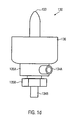
- Fig. 1 a schematically shows a cleaning system 100 in which a holder 110 is provided which is adapted to receive one or more milking cups 120 and to hold them in position during a cleaning sequence based on at least two different cleaning fluids.
- the holder 110 is provided in an illustrative embodiment in the form of a chamber in which, if necessary, a certain level of liquid, for example in the form of water, etc., can be maintained.
- the holder 110 is also advantageously designed such that the teat cups 120 can be received substantially with their entire volume, ie, over their entire length of travel, so that efficient rinsing and wetting of substantially all of the outer surface of the teat cups 120 is carried out if required can be, if necessary.
- the holder 110 may be formed such that at least the interior of the Melkbecher 120 is accessible for proper cleaning and disinfecting, without substantially the entire outer area of the teat cups 120 is enclosed by the holder 110.
- one or more fluid dispensing devices 130 are provided, which are configured and arranged such that at least a first cleaning fluid 131 and a second cleaning fluid 132, which are obtained from corresponding fluid sources 131a, 132a, can be dispensed. That is, the one or more dispensers 130 may introduce at least the two cleaning fluids 131, 132 into the teat cups 120, at least into a lower portion thereof. In this way, the milking cup 120 can be acted on at a single predetermined cleaning position with different cleaning fluids in a very space-saving manner.
- each of the dispensers 130 is provided with a respective outlet port 133 which may be connected to the fluid source 132a via a corresponding feed line 132b and associated valve 132c.
- the outlet port 133 can be connected to the fluid source 131a via a corresponding feed line 131b and a corresponding valve device 131c, wherein a corresponding introduction of the cleaning fluids 132, 131 can take place according to the requirements of the cleaning process.
- the efficiency for example, in view of the penetration depth of the respective cleaning liquid into the teat cup 120 can be suitably controlled by adjusting the pressure in the fluid sources 132a, 131a and / or the function of the valve means 132c, 131c and / or the size and shape the outlet port 133 are suitably selected.
- the outlet opening 133 may be provided in the form of a nozzle, wherein by adjusting the pressure conditions in the corresponding fluid sources 132a, 131a, a wetting of the inner surfaces of the milking cup 120 can be achieved.
- a suitable liquid level can be adjusted during certain operating phases in the holder 110, if desired.
- Fig. 1 b shows a schematic cross-sectional view of a portion of the output device 130, wherein one or more first outlet openings 133a and one or more second outlet openings 133b are provided, which communicate respectively via the respective valve means 132c, 131c with the corresponding fluid sources 131 a, 132 a.
- a mutual influence of the corresponding cleaning fluids can also be significantly reduced within the output device 133 if necessary.
- Fig. 1 c shows a schematic plan view of the dispensing device 133, wherein a plurality of first outlet openings 133a and a plurality of second outlet openings 133b are arranged so that a possible isotropic wetting of the teat cup 120 is given for both types of fluids. That is, in the illustrated embodiment, a first opening 133a and a second opening 133b are alternately provided adjacent to each other in the circumferential direction, so that a uniform discharge of the fluids 131, 132 is achieved.
- Fig. 1d 1 schematically shows a side view of the dispensing device 130 according to an embodiment in which corresponding connections 134a, 134b are provided in order to liquid-tightly connect the feeders 134a, 134b to the outlet opening 133 via corresponding screw connections 135a, 135b.
- the connection 134a with the screw connection 135a can establish a fluid-tight connection with a base body in which the outlet opening 133 and the corresponding channel are formed, which can reach the outlet opening 133 via suitably positioned inlet openings (not shown) in the base body.
- a pan or chamber 136 is provided, which may also advantageously hold a certain amount of cleaning fluid when continuous wetting of respective areas of the teat cup 120 is desired.
- the corresponding elements are mechanically connected to one another by screw connections and corresponding seals, so that, if required, the individual parts can be dismantled and, for example, cleaned.
- one or more of the described components may be provided as a unit, so that corresponding machining can be carried out inexpensively.
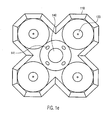
- Fig. 1e schematically shows a plan view of the cleaning system 100, with their output devices 130 are provided in the holder 110, so as to four, for example Melkbecher record simultaneously.
- a spraying device 140 is provided, in which one or more outlet openings 141 are connected to a corresponding source of cleaning agents, in order to thereby wet outer areas of the teat cups with the cleaning agent, for example water.
- the cleaning agent for example water.
- the teat cups 130 are brought to the holder 110, this being done automatically by means of a transport device, as explained in more detail below, or manually.
- the partially funnel-shaped design of the holding device 110 makes it possible to efficiently guide the milking cups 120 as soon as mechanical contact with the holder 110 has taken place.
- the teat cups 120 are substantially independently centered by the tapered shape of the holder 110 in the illustrated embodiments and guided to the appropriate cleaning positions.
- the cleaning position of the milking cups 120 is shown as leaving a distance to the bottom of the holder 110, while in other embodiments, the milking cups are lowered to the bottom of the holder 110.
- the dispenser 130 may be activated prior to reaching the final cleaning position to dispense a cleaning fluid.
- the cleaning position which is to be understood as a position in which the teat cups 120 are exposed to cleaning fluids by the dispenser 130, is changed during certain operating phases to allow for more efficient wetting.
- the height position of the teat cups 120 may be varied to allow varying depth of penetration of the cleaning fluids.
- a corresponding variable height position may be achieved by suitable means, such as a transport device as will be described later.
- the spraying device 140 (see FIG Fig. 1 e) be activated so as to achieve already an efficient cleaning on the outside of the teat cups 120 over an extended length range.
- the milking cups 120 are thus arranged so that at least part of the interior of the milking cups 120 can be wetted by means of the dispensing devices 130 with different cleaning fluids.
- a desired amount and type of cleaning fluid may be introduced via the dispenser 130.
- a corresponding automated sequence can be set in motion so that a predefined cleaning sequence takes place without manual access.
- both the duration of action and the amount of the cleaning fluid supplied can be efficiently controlled by means of the cleaning system 100, so that constant operating conditions are maintained over a plurality of cleaning processes, while maintaining appropriate regulations.
- a corresponding cleaning sequence comprising at least the aforementioned three steps may be performed in a time window of 30 to 60 seconds, but any other timings are possible as needed.
- a corresponding dynamic adaptation may also take place, for example if more intensive cleaning is required.
- the required disinfection between the individual milking processes can be achieved, for example, by feeding an amount of 0.1 to 0.5 liters of peracetic acid for each four milking cups 120, whereby the corresponding amount of used cleaning fluid can be removed after each individual cleaning process. as will be explained in more detail below, so that each individual cleaning operation can be carried out on the basis of a substantially uncontaminated, newly supplied cleaning fluid.
- a corresponding disinfection of the cleaning system 100 itself can be carried out if, for example, a corresponding cleaning liquid is held in the holder 110 without the presence of the milking cups 120, or if this is applied by means of the dispensing devices 130 and / or the spraying device 140, if provided when no milking cups 120 are positioned.
- a corresponding cleaning liquid is held in the holder 110 without the presence of the milking cups 120, or if this is applied by means of the dispensing devices 130 and / or the spraying device 140, if provided when no milking cups 120 are positioned.
- an active reduction in the amount of cleaning fluid (s) may be brought about after a desired exposure time, such as by mechanical movement of the teat cups 120, or the like, as described in more detail below.
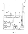
- Fig. 1f 12 schematically illustrates the cleaning system 100 according to another illustrative embodiment in which a controller 150 is provided operatively connected to the valve devices 132c, 131c to thereby control the supply of the respective cleaning fluid 132,131.
- the controller 150 may, in illustrative embodiments, have implemented a corresponding cleaning sequence such that in a timely coordinated manner, the respective fluid sources 132a, 131a are connected to the respective dispensers 130 so that a desired amount of corresponding cleaning fluid is supplied.
- the controller 150 may suitably adjust the exposure time of respective cleaning fluids, wherein in some illustrative embodiments, a predetermined exposure time is predetermined, while in other illustrative embodiments, one or more parameter values may be changed to dynamically determine the exposure time and / or amount to control the supplied cleaning fluids.
- the cleaning system 100 may have a corresponding sensor device (not shown) which outputs a signal as a function of the degree of contamination of the milking cup 120 positioned in the system 100, on the basis of which the exposure time and / or the amount is set.
- a selection of different cleaning programs may be implemented, which may then be selectively retrieved, for example by manual selection.
- a device 160 is also provided, with which a desired level of a cleaning fluid can be held in the holder 110, if this is designed in the form of a chamber or a trough.
- the device 160 may include a reservoir 161 into which used cleaning fluid is introduced via a respective drain line 162.
- the drain line 162 may be provided with a controllable valve device so that corresponding liquids can be drained off in a controlled manner. In this way, a suitable liquid level can be set, which can be maintained at a desired level by appropriate controlled discharge of liquid.
- the drain line 162 may be represented by an opening in the bracket 110, which opening may then be fluid-tightly sealed in the presence of a teat cup 120.
- a bleed line 163 may be provided with controllable valve means 163c to maintain the level in the fixture 110 at a desired level when needed, the valve means 163c being operable when in certain operating phases, such as a final cleaning higher liquid level is desired.
- the restriction device 160 may include other suitable means, such as a riser, etc., so that when a set height is exceeded, liquid drains into the reservoir 161.
- a sensor device for example in the form of a pressure sensor, may be present in order to obtain a signal as a function of the filling level in the holder 110, which can then be evaluated by the control device 150 in order to set the corresponding filling level, for example by the valve device 163c is controlled appropriately.
- a desired liquid level in the cleaning system 100 can be maintained, in which case when positioning the teat cups 120, the corresponding liquid with a corresponding amount of residual liquid, which exits the Melkbechem 120, can be discharged into the reservoir 161.
- the controller 150 may then initiate a suitable cleaning sequence, wherein, if necessary, the respective cleaning fluids may be maintained in the holder 110 by means of the means 160 having a desired liquid level.
- the beginning of a respective cleaning sequence may, in one illustrative embodiment, be determined based on a sensor device 151 which may supply a signal dependent on the positioning of the teat cups 120 to the controller 150, on the basis of which appropriate control activities may be initiated.
- the sensor device 151 may be a pressure-sensitive sensor device, so that the presence of a milking cup 120 can be detected.
- the sensor device 151 may be used for level detection within the fixture 110 when there is no teat cup 120.
- the sensor device 151 may be configured in any other suitable manner to detect the presence of a milking cup 120.
- the sensor device 151 may include a pressure switch that outputs a corresponding signal upon contact with the teat cup 120.
- proximity switches or other means may be provided to generate a signal dependent on the relative position of the milking cup 120 relative to the holder 110.
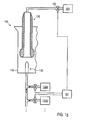
- Fig. 1g schematically shows the cleaning system 100 according to another illustrative embodiment.
- the control device 150 is provided in the form of a vacuum control device, so that an operating vacuum, which is generated by a vacuum source 181, is controllable in the milking cup 120 by the control device 150 by means of a valve device 152.
- the operating vacuum in the milking cup 120 may be activated and deactivated depending on the positioning of the milking cup 120.
- the controller 150 can then deactivate the vacuum, so that corresponding amounts of milk remaining can then flow off in a controlled manner and can thus be disposed of. Then, the further course of the cleaning process in the system 100 can proceed in a suitable manner, for example by means of the controller 150, in order to introduce one or more cleaning fluids into the teat cup 120 via the dispenser 130 in a suitable manner.
- Fig. 2a schematically shows a milking system 280, in which a vacuum source 281 is formed to provide a required for milking operating vacuum.
- the vacuum source 281 is further connected to a milk collecting device 282 and a corresponding milking harness 221, which in turn has a plurality of milking cups 220.
- a transport device 284 is provided in the milking installation 280, which is designed so that the milking equipment 211 can be moved after a milking operation in a suitable manner to a cleaning installation 200 in order to allow intermediate disinfection after individual milking operations.
- the cleaning system 200 is designed as described above in connection with the cleaning system 100 is.
- the cleaning system 200 is in particular designed to supply two or more different cleaning fluids by means of an output device associated with each milking cup 220, such as the dispensing device 130 as described above.
- a holding device 283 is further provided in the milking installation 280, which is designed so that the milking equipment 211, ie in particular the milking cups 220, are arranged so that they can be suitably applied manually to the udder of an animal.
- the holding device 283 may be designed so that during the operating phase for milking, ie during a milking process and during the application and removal of the individual milking cup 220, a substantially horizontal direction through the holding device 283 and thus a substantially horizontal position and Orientation of the milking cups 220 contained therein is defined.
- the holding device 283 may be configured to carry out the process of removing the milking cups 220 in an automated or semi-automated manner, for example by momentarily interrupting the operating vacuum upon the action of an operator so that the milking cups 220 fall off and are automatically retrieved by the holding device 283 can be.
- the process of removing the milking cups 220 may also be performed manually, with the holding device 283 allowing for individually removing the milking cups 220 and returning them to the holder 283.
- the transport device 284 can position the milking cluster 221 in a suitable manner above the cleaning system 200, in order to allow corresponding positioning of the milking cups 220 at the cleaning positions provided for this purpose.
- the transport device 284 may be designed so that the holding device 283 is arranged substantially vertically above the cleaning system 200 in order to enable insertion of the milking cups 220 into the corresponding holder 210 of the cleaning system 200.
- Fig. 2b schematically shows the milking system 280, wherein the holding device 283 is positioned vertically.
- a corresponding vacuum drive means for example in the form of the controller 150, or the like, is provided, so that at least during the positioning phase in which residual milk can flow out in an uncontrolled manner, the operating vacuum in the teat cup 220 is applied, so that substantially no contamination of the cleaning system 200 outside of the holder 210 is caused by residual milk.
- the operating vacuum again be deactivated so that the residual milk flows into the holder 210 controlled.
- the operating vacuum may continue to be applied until the teat cups 220 are positioned in the holder 210.
- the lowering of the teat cups 220 is already carried out with a cleaning agent, so that the corresponding outer sides of the teat cups 220 can be efficiently cleaned over the entire length or at least a substantial part thereof.
- the lowering of the teat cups 220 can be accomplished by means of the transport device 284 and / or the holding device 283, for example, by means of unrolling the supply hoses for the teat cups 220, then positioning them in the holder 210. Thereafter, a corresponding cleaning sequence can be carried out, as explained above.
- the height position of the teat cups can be varied as needed during the supply of one or more cleaning fluids for the wetting of the interior of the teat cups 220.
- the milking cups 220 are subjected to an active "dehumidification" process after one or more process steps to remove cleaning fluid from the milking cup 220.
- the transport means 284 is actuated to lift the milking cups 220 in the holder 210 and mechanically move them to accelerate the dripping of the liquid.
- an actuator 285 is provided in the transport device 284, which causes a suitable movement of the teat cups.
- the active "dehumidification" of the teat cups 220 may, for example, be done after each introduction of a fluid and after the desired exposure time, or is performed only after certain steps. A corresponding mechanical movement can be carried out for several seconds or longer if required. If corresponding deflections of the teat cups 220 are too large so that they can not be performed within the holder 210 in the raised state of the teat cups, the transport means 284 can approach a suitable "dry position" in which the required "freedom of movement" of the teat cups is given.
- a device for generating a gas flow for dehumidifying the milking cups 220 may be provided, so that preferably an outwardly directed flow is built up in the milking cup 220.
- a fluid source can be connected by suitable controllable valve devices with the interior of the milking cup via the corresponding milk lines.
- the milking harness 221 can then be used for another milking.
- the transport means 284 may move the holding means 283 into a suitable, i. bring substantially horizontal position so that the teat cups 220 are ready for docking.
- the cleaning system 200 can be used in different operating modes, as also explained above, so that, for example, a further cleaning of the milking harness 221 can be initiated if required, for example cleaning fluid can also be supplied through the connecting lines of the milking cups 220 into this can be introduced, which can then be discharged efficiently controlled in the cleaning system 200. Also, in such a cleaning phase, a high liquid level can be generated within the holder 210, so that an efficient cleaning of the outer sides of the teat cups 220 can be ensured.
- the operating vacuum can be activated and deactivated in a suitable manner, so as to enable efficient flushing of all fluid connections involved, in particular during a final cleaning.
- a control device for example the control device 150, may be provided in the cleaning system 200 in order to control appropriately controllable valve devices for connecting the teat cups to a rinsing liquid reservoir, so that cleaning liquid can flow through all fluid connections in a suitable manner.
Abstract
Description
Die vorliegende Erfindung betrifft das Melken von Milchtieren unter Anwendung eines Melkgeschirrs mit mehreren Melkbechern, wobei insbesondere eine Reinigung bzw. Desinfektion der Melkbecher zwischen den einzelnen Melkvorgängen ausgeführt wird.The present invention relates to the milking of dairy animals using a milking cluster with a plurality of milking cups, wherein in particular a cleaning or disinfection of the milking cups between the individual milking operations is carried out.
Derartige Reinigungsanlagen sind beispielsweise aus
Mit der zunehmenden Globalisierung der Agrarmärkte werden an die Erzeuger von Milch und Milchprodukten zunehmend höhere Anforderungen gestellt. Zum einen muss die Milch möglichst preisgünstig erzeugt werden, andererseits ist jedoch auch eine hohe Qualität der Milch beizubehalten. Um die Erzeugung großer Mengen von Milch in einem Agrarbetrieb zu ermöglichen, werden voll automatische oder semiautomatische Melkanlagen eingesetzt, so dass eine Vielzahl von Tieren mit moderat geringem Personalaufwand gemolken werden können. Zwar bieten vollautomatisierte Melkanlagen, sogenannte Melkroboter, die Möglichkeit, das für die Erzeugung der Milch erforderliche Personal zahlenmäßig stark zu reduzieren, da im Prinzip der gesamte Melkvorgang automatisch ablaufen kann, so sind dennoch die äußerst hohen Anschaffungskosten sowie der Aufwand in Bezug auf Wartung des vollautomatisierten Systems wichtige Gesichtspunkte, die das Einführen vollautomatisierter Anlagen insbesondere in kleineren und mittleren Agrarbetrieben als ungünstig erscheinen lassen. Daher werden in vielen Betrieben semiautomatische Melkanlagen betrieben, in denen bestimmte Handlungen während des Melkvorganges manuell durchgeführt werden, wobei insbesondere das Anlegen der Melkbecher an die Zitzen der Tiere manuell erfolgt.With the increasing globalization of agricultural markets, increasing demands are made on producers of milk and dairy products. On the one hand, the milk must be produced as inexpensively as possible, on the other hand, however, a high quality of the milk must be maintained. In order to enable the production of large quantities of milk in an agricultural enterprise, fully automatic or semi-automatic milking systems are used, so that a large number of animals can be milked with a modestly low personnel expenditure. Although fully automated milking systems, so-called milking robots, offer the possibility of greatly reducing the personnel required to produce the milk, since in principle the entire milking process can take place automatically, the extremely high initial costs and the outlay for maintenance of the fully automated milking system are nonetheless Systems are important considerations that make the introduction of fully automated systems, especially in small and medium-sized farms as unfavorable. Therefore, in many farms semi-automatic milking systems are operated in which certain actions are performed manually during the milking process, in particular, the application of the milking cups to the teats of the animals is done manually.
Der Melkvorgang selbst findet in der Regel so statt, dass durch Erzeugen eines gewissen Unterdruckes in einem Melkbecher ein Milchfluss von der Zitze in den Melkbecher in Gang gesetzt wird, von wo die ermolkene Milch dann in eine entsprechende Sammelleitung abgeführt wird. Seit der Einführung automatischer und semiautomatischer Melkanlagen in Agrarbetrieben ist viel Aufwand betrieben worden, um einen möglichst effizienten Betrieb von Melkanlagen zu gewährleisten, da es für einen dauerhaften hohen Ertrag äußerst wichtig ist, einen dem natürlichen Saugvorgang des Kalbes an dem Euter des Muttertieres nachempfundenen Melkvorgang mittels der automatischen Melkanlage auszuführen. D. h., beim automatisierten bzw. semiautomatisierten Melkvorgang soll einerseits ein geringes Maß an Eingreifen durch einen Bediener erforderlich sein, um damit den Anteil an Personalkosten in einem Agrarbetrieb gering zu halten, andererseits ist jedoch ein hohes Maß an "Natürlichkeit" des automatisierten Melkvorgangs sicherzustellen. Es zeigt sich, dass ein dauerhaft hoher Ertrag von Milchtieren in der Regel nur dann zu gewährleisten ist, wenn ein über das gesamte Jahr hinweg ein hoher Ausmelkungsgrad erreicht wird, da dann die milch produzierenden Zellen, d. h. die Alveolen, nachhaltig zu einer ständigen Produktion von Milch angeregt werden. Dazu ist es in der Regel erforderlich, gewisse physiologische Aspekte, etwa eine ausreichende Stimulation, geeignete Druckverhältnisse an der Zitze, sowie ein gewisses Maß an Hygiene einzuhalten. Somit kann bereits durch den Melkvorgang selbst die Menge und die Qualität der Milch bestimmt werden. D. h., bei einer möglichst guten Anpassung des maschinellen Melkvorgangs an die physiologischen Gegebenheiten des Milchtieres lässt sich eine dauerhafte Eutergesundheit erreichen, die wiederum die Vorraussetzung ist, langfristig einen hohen Ertrag bei hoher Qualität der Milch zu erreichen. Beispielsweise ist ein ausreichend hoher Ausmelkungsgrad nicht nur für die insgesamt erzeugte Milchmenge, sondern auch für die Qualität der Milch ein wesentlicher Aspekt, da insbesondere die Keimzahl der Milch langfristig durch einen effizienten Melkvorgang deutlich reduziert werden kann.The milking process itself usually takes place in such a way that, by generating a certain negative pressure in a milking cup, a milk flow from the teat into the milking cup is set in motion, from where the milked milk is then discharged into a corresponding collecting line. Since the introduction of automatic and semi-automatic milking systems in agricultural operations, much effort has been expended to ensure the most efficient operation of milking systems, as it is extremely important for a long-term high yield, a milking the natural suckling process of the calf on the mother's udder mimicking to run the automatic milking system. That is, in the automated or semi-automated milking process, on the one hand, a low level of intervention by an operator is required to minimize the proportion of personnel costs in an agricultural business, but on the other hand, a high degree of "naturalness" of the automated milking process sure. It turns out that a permanently high yield of dairy animals usually only It is then necessary to ensure that a high degree of oozing is achieved throughout the year, since then the milk-producing cells, ie the alveoli, are sustainably stimulated to produce milk continuously. For this it is usually necessary to comply with certain physiological aspects, such as sufficient stimulation, appropriate pressure conditions on the teat, and a certain level of hygiene. Thus, even the amount and quality of the milk can be determined by the milking process itself. In other words, if the automatic milking process is adapted as well as possible to the physiological conditions of the milk animal, a lasting udder health can be achieved, which in turn is the prerequisite for achieving a long-term high yield and high quality of the milk. For example, a sufficiently high degree of milk release is an essential aspect not only for the total amount of milk produced but also for the quality of the milk, since in particular the germ count of the milk can be significantly reduced in the long term by an efficient milking process.
Neben den vielen physiologischen Aspekten, die beim maschinellen Melken zu berücksichtigen sind, gibt es jedoch auch hygienische Vorgaben, die für die Qualität der Milch entscheidend sind. Beispielsweise werden selbst in kleineren und mittleren Agrarbetrieben eine Vielzahl von Milchtieren mit dem gleichen Melkgeschirr gemolken. Hierbei ist es besonders wichtig, die Verschleppung von Keimen von einem Tier zum anderen möglichst einzuschränken oder zu verhindern, so dass ein hohes Maß an Tiergesundheit auch bei größeren Tierbeständen gewährleistet ist. Beispielsweise sieht der Gesetzgeber in den diversen Ländern entsprechende Regelungen vor, die in einer sogenannten Milchordnung verankert sind, die einen entsprechenden Hygienestandard gewährleisten sollen. Die Einhaltung dieser Hygienestandards ist jedoch nicht nur im Hinblick auf das Erfüllen der gesetzlichen Vorgaben wichtig, sondern führt langfristig auch zu einer besseren Tiergesundheit und damit auch zu einer höheren Milchleistung. Es werden daher eine Vielzahl von Systemen und Verfahren eingesetzt, um zwischen den einzelnen Melkvorgängen die Melkbecher zu reinigen und zu desinfizieren, wobei jedoch unter praxisnahen Bedingungen die Wirksamkeit dieser Einrichtungen und Verfahren z.T. sehr eingeschränkt ist. Beispielsweise ist für gewisse Reinigungsflüssigkeiten, etwa Peressigsäure, eine bestimmte Mindesteinwirkdauer erforderlich, so dass die gewünschte desinfizierende Wirkung erreicht wird. Andererseits kann ein zu lange andauernder Reinigungsprozess zu einer deutlichen Einbuße in der Gesamteffizienz der Melkanlage führen. Auch ist ein Kontakt der Reinigungsflüssigkeiten mit der abgemolkenen Milch möglichst zu vermeiden, um das Einbringen von Fremdstoffen in die Milch zu verhindern. Insbesondere bei semiautomatischen Melkanlagen ist die Effizienz und die Qualität des entsprechenden Reinigungs- bzw. Desinfiziervorganges in besonderem Maße von dem entsprechenden Bediener der Melkanlage abhängig, da in solchen Anlagen beispielsweise die Qualität und die Zusammensetzung des Desinfektionsmittels und der Reinigungsflüssigkeiten, die Einwirkdauer, und dergleichen von dem entsprechenden Bediener beeinflusst werden können. Unter solchen Bedingungen ist es häufig schwierig, die für den Melkvorgang und die Milchqualität günstigen Bedingungen einzuhalten, oder die an sich vorgegebenen gesetzlichen Auflagen werden nur unzureichend erfüllt. Beispielsweise ist im europäischen Markt eine Reinigungsprozedur nach einzelnen Melkvorgängen vorgeschrieben, in der nach dem Abnehmen der Melkbecher zunächst eine Spülung mit Wasser, so dann eine Beaufschlagung mit Peressigsäure und eine weitere Spülung mit Wasser auszuführen ist. Des weiteren ist eine gewisse Mindesteinwirkdauer der Peressigsäure zu beachten, um damit die angestrebte desinfizierende Wirkung zu erreichen. Um diese gesetzlichen Vorgaben zu verwirklichen, werden beispielsweise diverse Reinigungssysteme betrieben, die jedoch teilweise eine geringe Wirksamkeit aufweisen. Beispielsweise werden häufig in größeren Agrarbetrieben sogenannte Schleppbäder eingesetzt, in denen die Melkbecher nach dem Melkvorgang durch entsprechende Flüssigkeitsbäder gezogen werden, so dass zunächst Melkbecher durch ein Wasserbad gezogen werden, woran sich ein Peressigsäurebad anschließt und nachfolgend in der Regel ein Wasserbad durchlaufen wird. In einer derartigen Anordnung kann es jedoch zu einer starken Kontamination der Reinigungsflüssigkeiten selbst kommen, da insbesondere nach mehreren Reinigungsvorgängen entsprechende Verunreinigungen, die sich an den Außenseiten der Melkbecher anlagern können, in die entsprechenden Reinigungsbäder eingeführt werden. Die damit stetig anwachsende Belastung der Reinigungsflüssigkeiten führen damit unter Umständen zu einer stark reduzierten Desinfektionswirkung oder können sogar zu einer höheren Keimbelastung führen. Andererseits sind durch ein häufiges Austauschen der Reinigungsflüssigkeiten ein hoher zusätzlicher Arbeitsaufwand sowie eine große Menge an Desinfektionsmitteln erforderlich. In anderen halbautomatischen Melkanlagen wird der entsprechende Reinigungsvorgang manuell ausgeführt, so dass Wirksamkeit und Dauer des entsprechenden Reinigungsprozesses von der entsprechenden Person, den momentan herrschenden Bedingungen, und dergleichen abhängen können. Somit ist eine dauerhaft hohe Qualität und Zuverlässigkeit des entsprechenden Reinigungsprozesses unter Umständen nicht gewährleistet, insbesondere wenn eine hohe Arbeitsbelastung sowie ein unterschiedlicher Ausbildungsgrad des entsprechenden Fachpersonals anzutreffen sind.In addition to the many physiological aspects that have to be taken into account when it comes to automated milking, there are also hygienic requirements that are decisive for the quality of the milk. For example, even in small and medium-sized farms, a large number of dairy animals are milked with the same milking parlor. It is particularly important to minimize or prevent the spread of germs from one animal to another, so that a high level of animal health is ensured even with larger animal populations. For example, the legislator in the various countries provides for corresponding regulations, which are anchored in a so-called dairy order, which should guarantee a corresponding standard of hygiene. However, adhering to these hygiene standards is not only important in terms of fulfilling the legal requirements, but also leads in the long term to better animal health and thus to a higher milk yield. Therefore, a variety of systems and methods are used to clean and disinfect the teat cups between each milking, but under practical conditions, the effectiveness of these facilities and procedures is sometimes very limited. For example, for certain cleaning liquids, such as peracetic acid, a certain Mindesteinwirkdauer required so that the desired disinfecting effect is achieved. On the other hand, a too long-lasting cleaning process can lead to a significant loss in the overall efficiency of the milking system. Also, contact of the cleaning liquids with the milk to be milked should be avoided as much as possible in order to prevent the introduction of foreign substances into the milk. In particular, in semiautomatic milking systems, the efficiency and quality of the corresponding cleaning or disinfecting process is particularly dependent on the appropriate operator of the milking plant, since in such systems, for example, the quality and composition of the disinfectant and cleaning fluids, the exposure time, and the like can be influenced by the corresponding operator. Under such conditions, it is often difficult to comply with the conditions favorable for the milking process and the quality of the milk, or the statutory legal requirements are insufficiently met. For example, in the European market, a cleaning procedure is prescribed after individual milking operations, in which, after removing the milking cups, first a rinsing with water, then an application with peracetic acid and a further rinsing with water are to be carried out. Furthermore, a certain Mindesteinwirkdauer the peracetic acid must be observed in order to achieve the desired disinfecting effect. In order to realize these legal requirements, for example, various cleaning systems are operated, but in some cases have a low efficiency. For example, so-called tow baths are often used in larger farms, in which the teat cups are drawn by appropriate liquid baths after milking, so that first teat cups are drawn through a water bath, which is followed by a peracetic acid followed by a water bath is usually followed. In such an arrangement, however, it can lead to a strong contamination of the cleaning liquids themselves, since in particular after several cleaning operations corresponding impurities that can accumulate on the outsides of the teat cups are introduced into the corresponding cleaning baths. The ever-increasing load on the cleaning fluids thus possibly lead to a greatly reduced disinfecting effect or may even lead to a higher bacterial load. On the other hand, a frequent replacement of the cleaning fluids requires a high amount of additional work and a large amount of disinfectants. In other semi-automatic milking systems, the corresponding cleaning operation is carried out manually, so that the effectiveness and duration of the corresponding cleaning process can depend on the respective person, the prevailing conditions, and the like. Thus, a permanently high quality and reliability of the corresponding cleaning process may not be guaranteed, especially when a high workload and a different level of education of the appropriate specialist personnel can be found.
Es besteht somit ein Bedarf beim automatisierten oder halbautomatisierten Melkvorgang, die Reinigung bzw. Desinfektion von Melkbechem so zu verbessern, dass eine hohe Effizienz und eine gleichbleibende Qualität des Reinigungsvorgangs erreicht wird.Thus, there is a need in the automated or semi-automated milking process to improve the cleaning and disinfection of Melkbechem so as to achieve high efficiency and consistent cleaning quality.
Gemäß einem Aspekt der vorliegenden Erfindung wird diese Aufgabe durch eine Reinigungsanlage für Melkbecher mit den Merkmalen des Anspruchs 1 gelöst.According to one aspect of the present invention, this object is achieved by a milking cup cleaning system having the features of claim 1.
Durch die efindungsgemäß ausgebildete Reinigungsanlage ist es somit möglich, zumindest zwei unterschiedliche Reinigungsfluide durch eine Ausgabeeinrichtung in die Melkbecher einzubringen, so dass damit die Möglichkeit geschaffen ist, eine effiziente Reinigungs- bzw. Desinfektionssequenz durchzuführen. Die Zuführung zweier Reinigungsfluide mittels einer einzelnen Fluidausgabeeinrichtung erlaubt damit ein hohes Maß an Effizienz und Reproduzierbarkeit der Zuführung eines entsprechenden Reinigungsfluids, beispielsweise Wasser, Peressigsäure, und dergleichen, da jeder Melkbecher an einer bestimmten Reinigungsposition angeordnet werden kann, an der dann die Reinigungsfluide entsprechend einer gewünschten Sequenz und mit einer gewünschten Menge und Einwirkdauer zugeführt werden können. Somit wird durch das Vorsehen einer Fluidausgabeeinrichtung, die unterschiedliche Reinigungsfluide in dem Melkbecher einführen kann, ein hohes Maß an Flexibilität für das Einrichten einer geeigneten Reinigungs- bzw. Desinfektionssequenz erreicht, wobei die erforderlichen Vorgänge für die Handhabung der Melkbecher und der zur Beaufschlagung mit Reinigungsfluiden erforderliche Raumbedarf gering gehalten wird.It is thus possible, by means of the cleaning system designed according to the invention, to introduce at least two different cleaning fluids into the teat cups by means of an output device, thus creating the possibility of carrying out an efficient cleaning or disinfecting sequence. The supply of two cleaning fluids by means of a single fluid dispensing device thus allows a high degree of efficiency and reproducibility of the supply of a corresponding cleaning fluid, such as water, peracetic acid, and the like, since each milking cup can be arranged at a specific cleaning position, then the cleaning fluids corresponding to a desired Sequence and can be supplied with a desired amount and duration of action. Thus, by providing fluid dispensing means that can introduce different cleaning fluids into the teat cup, a high degree of flexibility is achieved in establishing a suitable cleaning or disinfecting sequence, with the operations required to handle the teat cups and to apply cleaning fluid Space requirement is kept low.
In einer weiteren vorteilhaften Ausführungsform ist eine mit der Fluidausgabeeinrichtung verbundene Zufuhreinrichtung mit einer ersten Speiseleitung, die über eine erste Ventileinrichtung mit der ersten Fluidquelle in Verbindung steht, und einer zweiten Speiseleitung, die über eine zweite Ventileinrichtung mit der zweiten Fluidquelle in Verbindung steht, vorgesehen.In a further advantageous embodiment, a feed device connected to the fluid dispensing device is provided with a first feed line, which communicates with the first fluid source via a first valve device, and a second feed line, which communicates with the second fluid source via a second valve device.
Durch diese Ausgestaltung der Reinigungsanlage ist eine individuelle Steuerung der Menge der einzelnen Reinigungsflüssigkeiten und/oder Gase gewährleistet, wobei durch die entsprechenden Speiseleitungen und Ventileinrichtungen eine gewünschte steuerbare Entkopplung von der Ausgabeeinrichtung möglich ist. Damit wird aber auch eine entsprechende Rückwirkung der Fluidausgabeeinrichtung auf die entsprechenden Fluidquellen deutlich reduziert, so dass dort die Integrität der Reinigungsfluide im Hinblick auf eine mögliche Kontamination gewährleistet ist, während auch gleichzeitig die Möglichkeit geschaffen ist, eine erforderliche Mindestmenge an Reinigungsfluid pro Sequenz vorzusehen, ohne dass der Reinigungsvorgang, durch eine variierende Zusammensetzung der Reinigungslösung oder eine schwankende Flüssigkeitsmenge beeinflusst werden. Auf diese Weise können stets konstante Betriebsbedingungen für die Reinigungssequenz aufrecht erhalten werden.By this design of the cleaning system an individual control of the amount of the individual cleaning liquids and / or gases is ensured by the corresponding feed lines and valve devices a desired controllable decoupling from the output device is possible. However, this also significantly reduces the corresponding reaction of the fluid dispensing device with the corresponding fluid sources, so that the integrity of the cleaning fluids with respect to possible contamination is ensured, while at the same time providing the possibility of providing a required minimum amount of cleaning fluid per sequence without that the cleaning process, be influenced by a varying composition of the cleaning solution or a fluctuating amount of liquid. In this way, constant operating conditions for the cleaning sequence can always be maintained.
In einer weiteren vorteilhaften Ausführungsform weist die Fluidausgabeeinrichtung eine Auslassöffnung auf, die von der ersten und der zweiten Fluidquelle gespeist werden kann. Mit diesem Aufbau kann der Volumenbedarf der Fluidausgabeeinrichtung sowie deren Komplexität sehr gering bleiben, da eine einzelne Auslassöffnung, beispielsweise in Form einer Einspritzdüse, etc., für mehrere Arten an Reinigungsfluiden verwendet werden kann. Gleichzeitig ergibt sich die Möglichkeit, eines der Reinigungsfluide, beispielsweise in Form von Wasser, zur Reinigung der Auslassöffnung zu verwenden, um damit bei Bedarf Reste des Desinfektionsmittels, beispielsweise Peressigsäure, effizient aus dem Bereich der Auslassöffnung zu entfernen, wenn beispielsweise die Reinigungsanlage selbst zu reinigen ist.In a further advantageous embodiment, the fluid dispensing device has an outlet opening which can be fed by the first and the second fluid source. With this structure, the volume requirement of the fluid dispensing device and its complexity can be kept very low, since a single outlet, for example in the form of an injection nozzle, etc., can be used for several types of cleaning fluids. At the same time, it is possible to use one of the cleaning fluids, for example in the form of water, for cleaning the outlet opening in order to efficiently remove any residues of the disinfectant, for example peracetic acid, from the area of the outlet opening, for example if the cleaning system itself is to be cleaned is.
In einer weiteren anschaulichen Ausführungsform weist die Fluidausgabeeinrichtung eine erste Auslassöffnung auf, die von der ersten Fluidquelle gespeist werden kann, und eine zweite Auslassöffnung, die von der zweiten Fluidquelle gespeist werden kann. Auf diese Weise ist ein hohes Maß an Flexibilität bei der Gestaltung der Reinigungssequenz gewährleistet, da beide Reinigungsfluide unabhängig voneinander in beliebiger Reihenfolge, Zeitdauer und Menge in den Melkbecher eingeführt werden können. Dabei können die Auslassöffnungen in geeigneter Weise so angeordnet werden, dass für beide Reinigungsfluide eine effizient Benetzung des Melkbecherinnerraums erreicht werden kann. In einigen anschaulichen Ausführungsformen werden mehrere entsprechende Auslassöffnungen vorgesehen, wobei ein Satz der Auslassöffnungen durch die erste Fluidquelle gespeist wird, während ein anderer Satz an Auslassöffnungen durch die zweite Fluidquelle gespeist wird. Dabei können sowohl die Anordnung als auch die Dimensionierung der entsprechenden Auslassöffnungen geeignet eingestellt werden, um damit eine gewünschte Art der Benetzung und eine Eindringtiefe in den Melkbecher zu erreichen.In another illustrative embodiment, the fluid dispenser has a first outlet port that may be fed by the first fluid source and a second outlet port that may be powered by the second fluid source. In this way, a high degree of flexibility in the design of the cleaning sequence is ensured because both cleaning fluids can be introduced independently of each other in any order, time and amount in the teat cups. In this case, the outlet openings can be arranged in a suitable manner so that efficient wetting of the teat cup interior space can be achieved for both cleaning fluids. In some illustrative embodiments, a plurality of respective outlet ports are provided, with one set of the outlet ports being fed by the first fluid source while another set of outlet ports are being fed by the second fluid source. In this case, both the arrangement and the dimensioning of the corresponding outlet openings can be suitably adjusted so as to achieve a desired type of wetting and a penetration depth into the teat cup.
In einer weiteren vorteilhaften Ausführungsform weist die Reinigungsanlage ferner eine Steuereinrichtung auf, die ausgebildet ist, die Zufuhr des ersten und des zweiten Reinigungsfluids zur Fluidausgabeeinrichtung zu steuern. Durch das Vorsehen der Steuereinrichtung können die Effizienz und der Automatisierungsgrad der entsprechenden Reinigungs- bzw. Desinfektionssequenz auf sehr flexible Art und Weise gehandhabt werden. Beispielsweise können in der Steuereinrichtung entsprechend vorgegebene zeitliche Abläufe implementiert sein, um damit in präziser Weise einen entsprechenden Reinigungsprozess reproduzierbar nach jedem Melkvorgang durchzuführen. Auf diese Weise kann das hohe Maß an Variabilität, wie sie durch bedienergestützte Reinigungssequenzen auftreten, deutlich reduziert werden, wobei gleichzeitig die entsprechenden Bedingungen in den einzelnen Reinigungsprozess oder über längere Betriebsphasen hinweg bei Bedarf den aktuellen Gegebenheiten anzupassen. Wenn z.B. eine höhere Kontamination der Melkbecher erwartet oder festgestellt wird, kann darauf durch Abrufen einer geeigneten Sequenz reagiert werden, wobei eine entsprechende Reaktion auf Grundlage reproduzierbarer Steuenrngsabläufe erfolgt.In a further advantageous embodiment, the cleaning system further comprises a control device, which is designed to control the supply of the first and the second cleaning fluid to the fluid dispensing device. By providing the control device, the efficiency and the degree of automation of the corresponding cleaning or disinfection sequence can be handled in a very flexible manner. For example, predetermined time sequences can be implemented in the control device in order to perform a corresponding cleaning process in a precise manner reproducibly after each milking process. In this way, the high degree of variability, as they occur through operator-assisted cleaning sequences, can be significantly reduced while at the same time adapting the respective conditions in the individual cleaning process or over longer operating phases if necessary to the current circumstances. If e.g. a higher contamination of the teat cups is expected or determined, can be responded thereto by retrieving an appropriate sequence, with a corresponding response based on reproducible control sequences.
In einer vorteilhaften Ausführungsform ist die Steuereinrichtung ausgebildet, das Zuführen des ersten und des zweiten Reinigungsfluids zeitlich aufeinanderfolgend zu veranlassen. Wie bereits erläutert ist, ist häufig eine durch gesetzliche Bestimmungen festgelegte Reihenfolge des Zuführens von mehreren Reinigungsfluiden erforderlich, so dass ein entsprechender Zeitablaufplan in der Steuereinrichtung eingerichtet werden kann. Insbesondere durch die zeitlich sequenzielle Ausgabe der verschiedenen Reinigungsfluide kann zum einen eine effiziente Desinfizierung erreicht werden, wobei gleichzeitig die entsprechenden Mengen der Reinigungsfluide in präzise Weise reproduzierbar bereitgestellt werden können. So kann beispielsweise durch die zeitlich aufeinanderfolgende Zuführung des ersten und des zweiten Reinigungsfluids nicht nur die Menge in geeigneter Weise dosiert werden, sondern es kann auch die jeweilige Einwirkdauer in geeigneter Weise gesteuert werden, so dass beispielsweise eine Reinigungssequenz in der Steuereinrichtung eingerichtet sein kann, die das Zuführen von Wasser, das anschließende Zuführen eines Desinfektionsmittels, etwa Peressigsäure mit einer entsprechend eingestellten Einwirkdauer, und ein nachfolgendes Zuführen von Wasser zuverlässig und reproduzierbar gewährleistet, wobei insgesamt eine geringe Menge an Reinigungsfluid ausreichend ist und der Platzbedarf für die entsprechende Reinigungssequenz gering bleibt.In an advantageous embodiment, the control device is designed to cause the supply of the first and the second cleaning fluid in time sequentially. As already explained, an order of supplying a plurality of cleaning fluids prescribed by legal regulations is often required, so that a corresponding time schedule can be established in the control device. In particular, by the temporally sequential output of the various cleaning fluids, on the one hand, an efficient disinfection can be achieved, while at the same time the corresponding quantities of the cleaning fluids can be provided in a precisely reproducible manner. Thus, for example, not only the amount can be metered in a suitable manner by the temporally successive supply of the first and second cleaning fluid, but it can also be the appropriate exposure time controlled in a suitable manner, so that, for example, a cleaning sequence can be set up in the control device the supply of water, the subsequent supply of a disinfectant, such as peracetic acid with a corresponding set exposure time, and a subsequent supply of water ensures reliable and reproducible, with a total of a small amount of cleaning fluid is sufficient and the space required for the corresponding cleaning sequence remains low.
Gemäß Anspruch 1 ist die Halterung zur Aufnahme eines Teils des Melkbechers in einer Kammer vorgesehen, die ausgebildet ist, einen vorgegebenen Fluidpegel zumindest in einer vorbestimmten Betriebsphase aufzunehmen bzw. zu halten. Durch das Vorsehen der entsprechenden Kammer kann die Effizienz der Reinigungsfluide sowie deren Verbrauch weiter verbessert werden, da zumindest in einigen Betriebsphasen des Reinigungsprozesses ein geeigneter Flüssigkeitspegel eingestellt und auch beibehalten werden kann, so dass entsprechend benetzte Bereiche sehr intensiv mit dem Reinigungsfluid wechselwirken können. Auf diese Weise kann das entsprechende Reinigungsfluid mit hoher Effizienz auf den Melkbecher einwirken, wobei in einigen Ausführungsformen entsprechende Mittel vorgesehen sind, um bei Bedarf den Fluidpegel abzusenken oder das entsprechende Fluid vollständig zu entfernen, obwohl dennoch die erforderlichen Mengen an Reinigungsfluiden im Vergleich zu vielen konventionellen Verfahren gering bleiben und auch eine entsprechende Kontamination der Reinigungsfluide zwischen den einzelnen Reinigungssequenzen gering bleibt.According to claim 1, the holder for receiving a part of the milking cup is provided in a chamber which is adapted to receive or hold a predetermined fluid level at least in a predetermined operating phase. By providing the corresponding chamber, the efficiency of the cleaning fluids and their consumption can be further improved, since at least in some operating phases of the cleaning process, a suitable liquid level can be adjusted and maintained, so that correspondingly wetted areas can interact very intensively with the cleaning fluid. In this way, the corresponding cleaning fluid can act on the teat cup with high efficiency, in some embodiments providing appropriate means for lowering the fluid level or completely removing the corresponding fluid, if required, while still providing the required quantities of cleaning fluids compared to many conventional ones Procedures remain low and also a corresponding contamination of the cleaning fluids between the individual cleaning sequences remains low.
Vorzugsweise ist eine Pegelbegrenzungseinrichtung vorgesehen, die geeignet ist, den Fluidpegel in der Kammer auf einen vorbestimmten maximalen Pegel zu begrenzen. Auf diese Weise können die Prozessbedingungen in flexibler Weise reproduzierbar eingestellt werden, ohne dass dadurch eine erhöhte Komplexität der Melkanlage erforderlich ist. Beispielsweise kann während gewisser Phasen der Reinigungssequenz ein definiertes Maß an Spülflüssigkeit, beispielsweise Wasser, wünschenswert sein, wobei dennoch durch die Begrenzungseinrichtung sichergestellt ist, dass höchstens eine maximal gewünschte Menge in der entsprechenden Kammer vorhanden ist. Vorteilhafterweise kann die Pegelbegrenzungseinrichtung so gestaltet sein, dass der in der jeweiligen Betriebsphase maximale Pegel einstellbar ist, so dass je nach Betriebsweise der entsprechende Benetzungsgrad und die zu verwendende Flüssigkeitsmenge durch den aktuellen maximalen Pegel vorgegeben sind. Wenn z.B. ein höherer Grad an Kontamination vorhanden ist, kann generell die Pegelhöhe beim Spülen und Desinfizieren erhöht werden, der dann bei normaler Betriebsweise wieder abgesenkt werden kann, so dass der Verbrauch an Reinigungsfluid wieder reduziert werden kann.Preferably, a level limiting device is provided which is adapted to limit the fluid level in the chamber to a predetermined maximum level. In this way, the process conditions can be adjusted in a reproducible manner in a flexible manner, without requiring an increased complexity of the milking installation. For example, during certain phases of the cleaning sequence, a defined amount of rinsing liquid, for example water, may be desirable, yet it is ensured by the limiting device that at most a maximum desired amount is present in the corresponding chamber. Advantageously, the level limiting device can be configured such that the maximum level that can be set in the respective operating phase is adjustable so that, depending on the mode of operation, the corresponding degree of wetting and the quantity of liquid to be used are predetermined by the current maximum level. If e.g. a higher level of contamination is present, the level of flushing and disinfecting levels can generally be increased, which can then be lowered again during normal operation, so that the consumption of cleaning fluid can be reduced again.
In einer weiteren vorteilhaften Ausführungsform ist eine Fluidentfeuchtungseinrichtung vorgesehen, die ausgebildet ist, den Anteil des ersten und/oder des zweiten Fluids in dem Melkbecher aktiv zu reduzierten. Typischerweise ist es vorteilhaft, nach dem Einbringen des Reinigungsfluids und nach einer gewünschten Einwirkdauer das entsprechende Reinigungsfluid effizient aus dem Melkbecher zu entfernen, um damit eine gegenseitige Beeinflussung der einzelnen Reinigungsfluide sowie eine mögliche Einwirkung auf die Milch zu reduzieren. Durch die erfindungsgemäße Fluidentfeuchtungseinrichtung kann der Vorgang des Abführens von Reinigungsfluiden aktiv unterstützt werden, indem beispielsweise geeignete Mechanismen, etwa ein Gasstrom, mechanische Bewegung, und dergleichen, eingesetzt werden, um den Anteil an Restfluid in dem Melkbecher zu verringern.In a further advantageous embodiment, a fluid moistening device is provided, which is designed to actively reduce the proportion of the first and / or the second fluid in the milking cup. Typically, it is advantageous, after the introduction of the cleaning fluid and after a desired exposure time, to efficiently remove the corresponding cleaning fluid from the teat cup in order to create a mutual cleaning fluid Influencing the individual cleaning fluids and a possible effect on the milk to reduce. By means of the fluid moistening device according to the invention, the process of discharging cleaning fluids can be actively assisted, for example by using suitable mechanisms, such as a gas flow, mechanical movement, and the like, to reduce the proportion of residual fluid in the milking cup.
In einer vorteilhaften Ausführungsform weist die Fluidentfeuchtungseinrichtung eine Aktuatoreinrichtung auf, die ausgebildet ist, den Melkbecher nach Beaufschlagen mit dem ersten oder zweiten Reinigungsfluid in Bewegung zu versetzen. Durch diese mechanische Bewegung kann somit in sehr effizienter Weise die Benetzung mit dem zuvor eingebrachten Reinigungsfluid verringert werden, so dass der nächste Prozessschritt in dem Vorgang mit geringer Beeinflussung durch das vorher eingebrachte Fluid ausgeführt werden kann. Beispielsweise kann die entsprechende Aktuatorvorrichtung ausgebildet sein, den Melkbecher aus der Halterung zu lösen und in eine schwingungsähnliche Bewegung zu versetzen, so dass das Abtropfen des Reinigungsfluids deutlich unterstützt wird.In an advantageous embodiment, the fluid dampening device has an actuator device, which is designed to set the milking cup in motion after being exposed to the first or second cleaning fluid. As a result of this mechanical movement, the wetting with the previously introduced cleaning fluid can thus be reduced in a very efficient manner so that the next process step in the process can be carried out with little influence by the previously introduced fluid. For example, the corresponding actuator device may be configured to release the teat cup from the holder and to set it in a vibration-like movement, so that the dripping of the cleaning fluid is clearly supported.
In anderen Ausführungsformen kann die Entfeuchtungseinrichtung den Melkbecher mit Luft oder Gas, etwa Stickstoff, beaufschlagen, so dass der Anteil an Fluid im Melkbecher vor dem nächsten Schritt reduziert wird. Somit kann durch eine aktive Verringerung des Fluidanteils die Zeitdauer des Gesamtvorgangs deutlich reduziert werden, ohne dabei die Effizient zu beeinträchtigen.In other embodiments, the dehumidifier may pressurize the teat cup with air or gas, such as nitrogen, such that the proportion of fluid in the teat cup is reduced prior to the next step. Thus, by actively reducing the fluid content, the duration of the overall process can be significantly reduced without compromising efficiency.
In einer weiteren vorteilhaften Ausführungsform umfasst die Reinigungsanlage ferner eine Sprüheinrichtung, die ausgebildet ist, zumindest einen Bereich der Außenseite eines oder mehrerer Melkbecher mit einem Reinigungsmittel zu benetzen. Mit einer entsprechenden zusätzlichen Sprüheinrichtung, die beispielsweise mit Wasser oder einem anderen geeigneten Reinigungsmittel betrieben werden kann, gelingt es damit auch Verschmutzungen an der Außenseite der Melkbecher zu reduzieren, ohne dass dabei eine deutliche Kontamination des ersten und des zweiten Reinigungsfluids, die durch die Ausgabeeinrichtung in den Innenraum des Melkbechers eingeführt werden, stattfindet. Auf diese Weise gelingt es, eine sehr effiziente Gesamtreinigung und Desinfektion der Melkbecher in den Zwischenphasen des Melkvorgangs durchzuführen, wobei die Außenreinigung, die Innenreinigung und die Desinfektion in einem sehr kleinen Volumen unter genau definierten Bedingungen stattfinden.In a further advantageous embodiment, the cleaning system further comprises a spraying device, which is designed to wet at least a portion of the outside of one or more teat cups with a cleaning agent. With a corresponding additional spraying, which can be operated for example with water or other suitable cleaning agent, it also succeeds in reducing contamination on the outside of the teat cups, without causing a significant contamination of the first and second cleaning fluid, which through the output device in the interior of the milking cup are introduced takes place. In this way, it is possible to carry out a very efficient overall cleaning and disinfection of the milking cups in the intermediate phases of the milking process, whereby the external cleaning, the internal cleaning and the disinfection take place in a very small volume under exactly defined conditions.
In einer weiteren vorteilhaften Ausführungsform ist eine Positionssensoreinrichtung vorgesehen, die ein Signal beim Positionieren des Melkbechers in der Halterung bereitstellt. Auf diese Weise kann eine effiziente Steuerung sowohl des Positioniervorgangs selbst, sofern dieser automatisch ausgeführt wird, als auch für die weitere Reinigungssequenz erreicht werden. Beispielsweise kann das Signal der Sensoreinrichtung die aktuelle Position des Melkbechers bezeichnen, beispielsweise kann das Signal angeben, ob der Melkbecher eine gewünschte Betriebsposition in der Reinigungsanlage erreicht hat.In a further advantageous embodiment, a position sensor device is provided which provides a signal when positioning the milking cup in the holder. In this way, an efficient control of both the positioning process itself, if it is carried out automatically, as well as for the further cleaning sequence can be achieved. For example, the signal of the sensor device may indicate the current position of the milking cup, for example the signal may indicate whether the milking cup has reached a desired operating position in the cleaning system.
In einer weiteren vorteilhaften Ausführungsform ist die Positionssensoreinrichtung mit der Steuereinrichtung verbunden, wobei die Steuereinrichtung die Zufuhr des ersten und/oder des zweiten Reinigungsfluids in Abhängigkeit des Signals steuert. So kann durch das entsprechende Signal beispielsweise die Zufuhr des ersten Reinigungsfluids zum geeigneten Zeitpunkt in Gang gesetzt werden, so dass die Benetzung des Innenraums des Melkbechers in zuverlässiger und reproduzierbarer Weise erreicht wird, ohne dass unnötig ein Teil des Fluids abläuft oder in der Reinigungsanlage ohne große Wirkung verteilt wird.In a further advantageous embodiment, the position sensor device is connected to the control device, wherein the control device controls the supply of the first and / or the second cleaning fluid in response to the signal. Thus, for example, the supply of the first cleaning fluid at the appropriate time can be initiated by the corresponding signal, so that the wetting of the interior of the milking cup is achieved in a reliable and reproducible manner, without unnecessarily running off a portion of the fluid or in the cleaning system without large Effect is distributed.
Gemäß Anspruch 1 ist eine Vakuumsansteuereinrichtung vorgesehen, die ausgebildet ist, einen Betriebsunterdruck im Melkbecher zu steuern. Durch die Vakuumansteuereinrichtung ist es möglich, die Reinigungssequenz in geeigneter Weise mit dem Betriebszustand des Melkbechers zu koordinieren. Beispielswiese ist es typischerweise notwendig, den Betriebsunterdruck, der während des Melkens im Melkbecher aufgebaut wird, zu unterbrechen, um damit die Melkbecher nach erfolgtem Melkvorgang von den Zitzen abzunehmen. Eine dauerhafte Deaktivierung des Melkunterdrucks im Bereich des Melkbechers kann jedoch zu einem Ausströmen von Restmilch führen, wobei diese dann unkontrolliert verteilt wird. Auf Grund der Vakuumansteuereinrichtung ist es jedoch möglich, das Betriebsvakuum gezielt wieder herzustellen, um damit ein ungesteuertes Ausströmen der Restmilch zu verhindern, solange der Melkbecher noch nicht in geeigneter Weise in der Halterung positioniert ist. Die Vakuumansteuereinrichtung ist insbesondere vorteilhaft im Zusammenwirken mit entsprechenden Halteeinrichtungen für Melkbecher, in denen diese manuelle oder automatisch von den Zitzen abgenommen und geeignet gehalten werden, ohne dass ein Abknicken der entsprechenden Milchschläuche für eine Deaktivierung des Melkvakuums im Bereich der Melkbecher sorgt. In diesem Falle kann die Vakuumansteuereinrichtung geeignete Druckbedingungen nach dem Abnehmen der Melkbecher bzw. nach dem automatischen Abfallen der Melkbecher einstellen, so dass das Ausströmen der Restmilch im Wesentlichen auf den Bereich der Halterung beschränkt ist, so dass die Restmilch in definierter Weise beispielsweise mittels Wasser abgeführt werden kann. Vorteilhafterweise ist die Vakuumansteuereinrichtung ausgebildet, den Betriebsdruck im Melkbecher in Abhängigkeit des Signals der Positionssensoreinrichtung zu steuern. Auf diese Weise kann zuverlässig sichergestellt werden, dass zumindest der Hauptanteil der Restmilch in der Halterung ausströmt, unabhängig davon, wie lange das Positionieren der einzelnen Melkbecher in der Halterung dauert.According to claim 1, a vacuum drive means is provided, which is designed to control an operating vacuum in the teat cup. By the vacuum drive means, it is possible to suitably coordinate the cleaning sequence with the operating state of the milking cup. For example, it is typically necessary to interrupt the operating vacuum built up during milking in the milking cup in order to remove the milking cups from the teats after milking has taken place. However, a permanent deactivation of the milking pressure in the region of the teat cup can lead to a leakage of residual milk, which is then distributed uncontrollably. Due to the vacuum control device, however, it is possible to selectively restore the operating vacuum in order to prevent an uncontrolled outflow of the residual milk, as long as the teat cup is not yet positioned in the holder in a suitable manner. The vacuum control device is particularly advantageous in cooperation with corresponding holding devices for milking cups in which they are manually or automatically removed from the teats and kept suitable, without causing a kinking of the corresponding milk tubes for deactivation of the milking vacuum in the region of the milking cups provides. In this case, the vacuum drive means may have suitable pressure conditions after the milking cups have been removed, or after the automatic falling off adjust the milking cup, so that the outflow of residual milk is essentially limited to the area of the holder, so that the residual milk can be removed in a defined manner, for example by means of water. Advantageously, the vacuum drive device is designed to control the operating pressure in the teat cup as a function of the signal of the position sensor device. In this way it can be reliably ensured that at least the main portion of the residual milk flows out in the holder, regardless of how long the positioning of the individual teat cups takes in the holder.
In einer weiteren Ausführungsform weist die Reinigungsanlage ferner eine Transporteinrichtung auf, die ausgebildet ist, die Melkbecher automatisch in der Halterung zu positionieren. Auf diese Weise gelingt selbst in halbautomatischen Melkanlagen, in denen ein gewisses Maß an manueller Bedienung erforderlich ist, sehr genau definierte Betriebsbedingungen während der Reinigungssequenzen zwischen den einzelnen Melkvorgängen einzuhalten. In anderen Ausführungsformen ist die Reinigungsanlage so gestaltet, dass auch bei einer manuellen Zuführung der Melkbecher eine entsprechende geeignete Positionierung der einzelnen Melkbecher gewährleistet ist. Dazu kann eine im Wesentlichen trichterförmige Öffnung so vorgesehen sein, dass bei Kontakt der Melkbecher mit den entsprechenden trichterförmigen Öffnungen eine geeignete Zentrierung der Melkbecher und somit eine Positionierung in der Halterung erfolgt. Somit kann auch bei einer rein manuellen Zuführung der Melkbecher zur Reinigungsanlage aufgrund der genauen Anordnung an der Reinigungsposition ein hohes Maß an Stabilität hinsichtlich der Betriebsbedingungen und der Reinigungssequenz erreicht werden.In a further embodiment, the cleaning system further comprises a transport device, which is designed to automatically position the teat cups in the holder. In this way, even in semi-automatic milking systems in which a certain degree of manual operation is required, very well-defined operating conditions can be maintained during the cleaning sequences between the individual milking operations. In other embodiments, the cleaning system is designed so that a corresponding suitable positioning of the individual milking cups is ensured even with a manual feed of the teat cups. For this purpose, a substantially funnel-shaped opening may be provided such that upon contact of the teat cups with the corresponding funnel-shaped openings, a suitable centering of the teat cups and thus positioning in the holder takes place. Thus, even with a purely manual feed of the teat cups to the cleaning system due to the exact arrangement of the cleaning position, a high degree of stability in terms of operating conditions and the cleaning sequence can be achieved.
Gemäß einem weiteren Aspekt der vorliegenden Erfindung wird eine Melkanlage bereitgestellt, wobei diese ein Melkgeschirr mit mehreren Melkbechern und eine Vakuumeinrichtung zur Bereitstellung eines Unterdrucks in dem Melkgeschirr zum Absaugen von Milch bereitstellt. Des weiteren ist eine Milchsammeleinrichtung vorgesehen, die mit dem Melkgeschirr und der Vakuumeinrichtung verbunden ist. Es ist ferner eine Reinigungsanlage ist vorgesehen, um Melkbecher zu reinigen, wobei die Reinigungsanlage gemäß Anspruch 1 ausgebildet ist.According to another aspect of the present invention, there is provided a milking facility which provides a milking cluster with a plurality of milking cups and a vacuum device for providing a vacuum in the milking cluster for sucking milk. Furthermore, a milk collecting device is provided, which is connected to the milking equipment and the vacuum device. It is also a cleaning system is provided to clean milking cups, wherein the cleaning system is designed according to claim 1.
Damit wird auch in der erfindungsgemäßen Melkanlage der Vorteil erreicht, dass durch Bereitstellen zweier Reinigungsfluide mittels einer einzelnen Ausgabeeinrichtung ein hohes Maß an Zuverlässigkeit und Stabilität der Betriebsbedingungen erreicht wird, wie dies zuvor bereits beschrieben ist. In einer weiteren vorteilhaften Ausführungsform ist ferner eine Halteeinrichtung für die Melkbecher vorgesehen, die ausgebildet ist, die Melkbecher für das manuell Anlegen der Melkbecher für den Melkvorgang zu positionieren. Zu diesem Zweck kann die Halteeinrichtung so gestaltet sein, dass die einzelnen Melkbecher im Wesentlichen horizontal angeordnet sind, so dass Melkbecher individuell manuell an eine Zitze des Tieres anzulegen sind. Durch diese Halteeinrichtung sind die Melkbecher nach Ende eines Melkvorgangs auch in geeigneter Weise positioniert, so dass sie sehr effizient in die entsprechende Reinigungsanlage überführt und dort in der entsprechenden Halterung positioniert werden können. Beispielsweise kann eine zuvor beschriebene Transporteinrichtung vorgesehen und mit der Halteeinrichtung verbunden sein, um damit die Halteeinrichtung nach einem Melkvorgang relativ zu der Reinigungsanlage so zu positionieren, dass die Melkbecher automatisch in der Halterung der Reinigungsanlage platziert werden. Auf diese Weise kann ein hohes Maß an Automatisierung selbst in semiautomatischen Melkanlagen erreicht werden, wobei dann der gesamte Vorgang nach dem Abnehmen der Melkbecher im Wesentlichen automatisiert und damit standardisiert ist, so dass gleichbleibende Bedingungen und damit eine gleichbleibend hohe Effizienz des Reinigungs- bzw. Desinfiziervorgangs erreicht wird.Thus, the advantage is achieved in the milking plant according to the invention that by providing two cleaning fluids by means of a single dispensing device, a high degree of reliability and stability of the operating conditions is achieved, such as this has already been described above. In a further advantageous embodiment, a holding device for the milking cups is also provided, which is designed to position the milking cups for the manual application of the milking cups for the milking process. For this purpose, the holding device may be designed so that the individual milking cups are arranged substantially horizontally, so that milking cups are individually to be manually applied to a teat of the animal. By means of this holding device, the milking cups are also suitably positioned after the end of a milking process, so that they can be transferred very efficiently into the corresponding cleaning system and positioned there in the corresponding holder. For example, a transport device described above may be provided and connected to the holding device, so as to position the holding device after a milking relative to the cleaning system so that the teat cups are automatically placed in the holder of the cleaning system. In this way, a high degree of automation can be achieved even in semi-automatic milking systems, in which case the entire process after removing the teat cups is substantially automated and thus standardized, so that constant conditions and thus a consistently high efficiency of the cleaning or disinfecting process is reached.
Vorteilhafterweise ist dabei die Vakuumansteuereinrichtung, wie sie beispielsweise zuvor beschrieben ist, so ausgebildet, dass der Betriebsunterdruck bei der Positionierung der Melkbecher aktiv bleibt, bis diese in der Halterung der Reinigungsanlage positioniert sind. Auf diese Weise kann ein Ausströmen der Restmilch deutlich reduziert werden, so dass die einzelnen Komponenten der Melkanlage nur in sehr geringer Weise durch Restmilch benetzt werden, so dass die Gefahr einer Keimbildung in der Melkanlage deutlich geringer ist.Advantageously, in this case, the vacuum activation device, as described above, for example, is designed so that the operating vacuum remains active during the positioning of the teat cups until they are positioned in the holder of the cleaning system. In this way, a leakage of the residual milk can be significantly reduced, so that the individual components of the milking system are wetted only very slightly by residual milk, so that the risk of nucleation in the milking plant is significantly lower.
Gemäß einem weiteren Aspekt der vorliegenden Erfindung wird ein Verfahren zur Reinigung von Melkbechern bereitgestellt, wobei das Verfahren das zeitlich aufeinanderfolgende Benetzen eines Teils des Innenraums der Melkbecher mit mindestens zwei unterschiedlichen Reinigungsfluiden in einem für jedes der zwei unterschiedlichen Reinigungsfluide gleichen Reinigungsbereich nach einem ersten Melkvorgang und das Verwenden der gereinigten Melkbecher für einen zweiten Melkvorgang umfasst.According to another aspect of the present invention, there is provided a method for cleaning milking cups, the method comprising sequentially wetting a portion of the interior of the milking cups with at least two different cleaning fluids in a same cleaning area for each of the two different cleaning fluids after a first milking operation and the first Use the cleaned milking cup for a second milking process.
Wie zuvor bereits erläutert ist, kann durch das Bereitstellen zweier unterschiedlicher Reinigungsfluide am gleichen Reinigungsort eine deutliche Verbesserung im Hinblick auf Effizienz und Durchsatz erreicht werden, da zum einen ein geringes Volumen der Reinigungsanlage und damit kurze Wege bei der Handhabung der Melkbecher ausreichend sind, da die für die Zwischendesinfektion erforderlichen Mittel an einer Position bereitgestellt werden können, während andererseits auch die Möglichkeit geschaffen wird, sehr konstante Betriebsbedingungen zu schaffen. Dies ist insbesondere vorteilhaft im Zusammenhang mit Melktechniken, in denen die Melkbecher beim Melkvorgang manuell angesetzt werden, so dass in derartigen Anlagen einerseits die Nachteile einer extrem hohen Automatisierung und der damit verknüpften Investitions- und Unterhaltungskosten reduziert werden können, wobei dennoch ein hohes Maß an Automatisierung, insbesondere im Hinblick auf eine effiziente Zwischendesinfektion der Melkbecher gelingt. So ist es beispielsweise in sehr effizienter Weise möglich, bei geringem Platzbedarf eine erste Menge eines ersten Reinigungsfluids, eine zweite Menge des zweiten Reinigungsfluids und danach eine dritte Menge des ersten Reinigungsfluids zuzuführen, um damit eine sehr effiziente Desinfektion der Melkbecher zu erreichen, wobei dies insbesondere in Einklang mit den jeweiligen geltenden Bestimmungen ausgeführt werden kann. Ferner gelingt es, eine sehr effiziente Desinfektion zu gewährleisten, wobei die Menge der aufzuwendenden Desinfektionsmittel pro Reinigungsvorgang relativ gering ist. Beispielsweise sind etwa 0,1 bis 0,5 Liter eines Reinigungsfluids, etwa beispielsweise Peressigsäure ausreichend, um vier Melkbecher einer üblichen Melkanlage gemäß den Vorgaben der Milchverordnung zu behandeln. Eine entsprechende Reinigungssequenz kann in 30 bis 60 Sekunden ausgeführt werden, so dass der Anteil der Zwischendesinfektion am Gesamtmelkvorgang gering bleibt.As already explained above, by providing two different cleaning fluids at the same cleaning location, a significant improvement in terms of efficiency and throughput can be achieved, since on the one hand a small volume of the cleaning system and in order that short distances in the handling of the milking cups are sufficient, since the means required for the intermediate disinfection can be provided at one position, while on the other hand also providing the possibility of creating very constant operating conditions. This is particularly advantageous in connection with milking techniques, in which the teat cups are set manually during the milking process, so that in such systems, on the one hand, the disadvantages of extremely high automation and the associated investment and maintenance costs can be reduced, while still a high degree of automation , especially with regard to an efficient intermediate disinfection of the milking cups succeed. For example, in a very efficient manner it is possible to supply a first quantity of a first cleaning fluid, a second quantity of the second cleaning fluid and then a third quantity of the first cleaning fluid in order to achieve a very efficient disinfection of the teat cups, in particular in accordance with the applicable rules. Furthermore, it is possible to ensure a very efficient disinfection, wherein the amount of disinfectant to be applied per cleaning process is relatively low. For example, about 0.1 to 0.5 liters of a cleaning fluid, such as peracetic acid, is sufficient to treat four milking cups of a conventional milking facility in accordance with the requirements of the Milk Ordinance. A corresponding cleaning sequence can be carried out in 30 to 60 seconds, so that the proportion of intermediate disinfection in the overall milking process remains low.
Weitere vorteilhafte Ausführungsformen, Aufgaben und Vorteile der vorliegenden Erfindung gehen aus der weiteren detaillierten Beschreibung sowie aus den angefügten Patentansprüchen hervor.Further advantageous embodiments, objects and advantages of the present invention will become apparent from the further detailed description and from the appended claims.
Weitere anschauliche Ausführungsformen werden nunmehr detaillierter mit Bezugnahme zu den begleitenden Zeichnungen beschrieben, in denen:
-
Fig. 1a schematisch eine Reinigungsanlage mit einer Halterung zur Aufnahme von Melkbechern und einer Ausgabeeinrichtung für die Beaufschlagung des Innenraums der Melkbecher mit verschiedenen Reinigungsfluiden gemäß einer anschaulichen Ausführungsform zeigt; -
Fig. 1 b eine Teilansicht einer Auslassdüse mit mehreren Auslassöffnungen gemäß einer anschaulichen Ausführungsform zeigt; -
Fig. 1 c eine Draufsicht der Düse ausFig. 1 b zeigt; -
Fig. 1 d eine schematische Darstellung einer Fluidausgabeeinrichtung mit Teilen entsprechender Speiseleitungen gemäß einer anschaulichen Ausführungsform zeigt; -
Fig. 1e schematisch eine Draufsicht der Reinigungsanlage ausFig. 1a gemäß einer anschaulichen Ausführungsform zeigt, wobei eine Sprüheinrichtung vorgesehen ist, um Außenbereiche der Melkbecher zu benetzen; -
Fig. 1f schematisch eine Reinigungsanlage mit Steuereinrichtung und einer Einrichtung für die Begrenzung des Fluidpegels gemäß weiterer anschaulicher Ausführungsformen zeigt; -
Fig. 1g schematisch eine Reinigungsanlage zeigt, in der eine Vakuumansteuereinrichtung zur Steuerung des Betriebsunterdrucks im Melkbecher zeigt; und -
Fig. 2a und2b schematisch eine Melkanlage mit einer erfindungsgemäßen Reinigungsanlage zeigen, wobei eine Transporteinrichtung vorgesehen ist, um in automatisierter Weise Melkbecher in der Reinigungsanlage zu positionieren.
-
Fig. 1a schematically shows a cleaning system with a holder for receiving milking cups and an output device for the admission of the interior of the teat cups with different cleaning fluids according to an illustrative embodiment; -
Fig. 1 b a partial view of an outlet nozzle with a plurality of outlet openings according to an illustrative embodiment; -
Fig. 1 c a plan view of the nozzleFig. 1 b shows; -
Fig. 1 d a schematic representation of a fluid dispensing device with parts of corresponding supply lines according to an illustrative embodiment shows; -
Fig. 1e schematically a plan view of the cleaning systemFig. 1a according to an illustrative embodiment, wherein a spraying device is provided to wet outside areas of the teat cups; -
Fig. 1f schematically shows a cleaning system with control device and means for limiting the fluid level according to further illustrative embodiments; -
Fig. 1g schematically shows a cleaning system, in which a Vakuumansteuereinrichtung shows to control the operating vacuum in the teat cup; and -
Fig. 2a and2 B schematically show a milking system with a cleaning system according to the invention, wherein a transport device is provided to position milking cups in the cleaning system in an automated manner.
Ferner sind in der Reinigungsanlage 100 eine oder mehrere Fluidausgabeeinrichtungen 130 vorgesehen, die so ausgebildet und angeordnet sind, dass zumindest ein erstes Reinigungsfluid 131 und ein zweites Reinigungsfluid 132, die aus entsprechenden Fluidquellen 131a, 132a erhalten werden, ausgegeben werden können. D. h., die eine oder die mehreren Ausgabeeinrichtungen 130 können zumindest die beiden Reinigungsfluide 131, 132 in die Melkbecher 120, zumindest in einen unteren Bereich davon, einführen. Auf diese Weise kann in sehr platzsparender Weise der Melkbecher 120 an einer einzelnen vorgegebenen Reinigungsposition mit unterschiedlichen Reinigungsfluiden beaufschlagt werden. Dazu ist in der dargestellten Ausführungsform jede der Ausgabeeinrichtungen 130 mit einer entsprechenden Auslassöffnung 133 versehen, die über eine entsprechende Speiseleitung 132b und ein zugehöriges Ventil 132c mit der Fluidquelle 132a verbunden werden kann. In ähnlicher Weise kann die Auslassöffnung 133 über eine entsprechende Speiseleitung 131b und eine entsprechende Ventileinrichtung 131c mit der Fluidquelle 131a verbunden werden, wobei eine entsprechende Einleitung der Reinigungsfluide 132, 131 entsprechend den Anforderungen des Reinigungsprozesses stattfinden kann. Durch Betätigung der entsprechenden Ventilelemente 132c, 131c ist somit die Menge und der Zeitpunkt für die Benetzung des Innenraums der Melkbecher 130 wählbar, wobei dies in automatisierter Weise erfolgen kann, wie dies nachfolgend detaillierter beschrieben ist, oder bei Bedarf auch manuell durchführbar ist. Auch kann die Effizienz, beispielsweise im Hinblick auf die Eindringtiefe der entsprechenden Reinigungsflüssigkeit in den Melkbecher 120 in geeigneter Weise gesteuert werden, indem der Druck in den Fluidquellen 132a, 131a und/oder die Funktion der Ventileinrichtungen 132c, 131c und/oder die Größe und Form der Auslassöffnung 133 geeignet gewählt werden. Beispielsweise kann die Auslassöffnung 133 in Form einer Düse vorgesehen werden, wobei durch Einstellen der Druckverhältnisse in den entsprechenden Fluidquellen 132a, 131 a eine Benetzung der Innenflächen des Melkbechers 120 erreicht werden kann. Bei Bedarf und bei entsprechender Ausbildung der Halterung 110, beispielsweise in Form einer Wanne mit entsprechenden Wänden und einem steuerbaren Ablauf für Flüssigkeit in der Wanne, kann auch ein geeigneter Flüssigkeitspegel während gewisser Betriebsphasen in der Halterung 110 eingestellt werden, wenn dies gewünscht ist.Furthermore, in the
Während des Betriebs der Reinigungsanlage 100 werden die Melkbecher 130 an die Halterung 110 herangeführt, wobei dies automatisch mittels einer Transporteinrichtung, wie dies nachfolgend detaillierter erläutert ist, oder manuell erfolgen kann. Bei der Annäherung der Melkbecher 120 an die Halterung 130 kann durch die teilweise trichterförmige Ausbildung der Halteeinrichtung 110 eine effiziente Führung der Melkbecher 120 erfolgen, sobald ein mechanischer Kontakt mit der Halterung 110 erfolgt ist. Somit werden die Melkbecher 120 im Wesentlichen selbständig durch die sich verjüngende Form der Halterung 110 in den dargestellten Ausführungsformen zentriert und an die entsprechenden Reinigungspositionen geführt. In
In einigen anschaulichen Ausführungsformen kann bereits während des Positioniervorgangs für die Melkbecher 120 die Sprüheinrichtung 140 (siehe
Während einzelner Schritte des Reinigungs- bzw. Desinfektionsprozesses kann eine aktive Verringerung der Menge des oder der Reinigungsfluide nach einer gewünschten Einwirkdauer herbeigeführt werden, etwa durch mechanische Bewegung der Melkbecher 120, oder dergleichen, wie dies nachfolgend noch ausführlicher beschrieben ist.During individual steps of the cleaning or disinfecting process, an active reduction in the amount of cleaning fluid (s) may be brought about after a desired exposure time, such as by mechanical movement of the teat cups 120, or the like, as described in more detail below.
In einer weiteren anschaulichen Ausführungsform ist ferner ein Einrichtung 160 vorgesehen, mit der in der Halterung 110, wenn diese in Form einer Kammer bzw. einer Wanne ausgeführt ist, ein gewünschter Pegel eines Reinigungsfluids gehalten werden kann. Beispielsweise kann die Einrichtung 160 ein Reservoir 161 aufweisen, in das gebrauchtes Reinigungsfluid über eine entsprechende Ablassleitung 162 eingeführt wird. In einigen anschaulichen Ausführungsformen kann die Ablassleitung 162 mit einer steuerbaren Ventileinrichtung versehen sein, so dass entsprechende Flüssigkeiten gesteuert abgelassen werden können. Auf diese Weise kann ein geeigneter Flüssigkeitspegel eingestellt werden, der durch entsprechendes gesteuertes Ablassen von Flüssigkeit auf einem gewünschten Niveau gehalten werden kann. In anderen Ausführungsformen kann die Ablassleitung 162 durch eine Öffnung in der Halterung 110 repräsentiert sein, wobei die Öffnung dann bei Vorhandensein eines Melkbechers 120 fluiddicht abgeschlossen werden kann. In anderen Ausführungsformen kann eine Ablassleitung 163 mit einer steuerbaren Ventileinrichtung 163c vorgesehen sein, um den Pegel in der Halterung 110 bei Bedarf auf einem gewünschten Niveau zu halten, wobei die Ventileinrichtung 163c betätigt werden kann, wenn in gewissen Betriebsphasen, beispielsweise bei einer Endreinigung, ein höheres Flüssigkeitsniveau gewünscht ist. In anderen Ausführungsformen kann die Begrenzungseinrichtung 160 andere geeignete Mittel aufweisen, etwa eine Steigleitung, etc., so dass bei Überschreiten einer eingestellten Höhe Flüssigkeit in das Reservoir 161 abläuft. Insbesondere kann auch eine Sensoreinrichtung, beispielsweise in Form eines Drucksensors, vorhanden sein, um damit ein Signal in Abhängigkeit der Füllhöhe in der Halterung 110 zu erhalten, das dann von der Steuereinrichtung 150 ausgewertet werden kann, um die entsprechende Füllhöhe einzustellen, indem beispielsweise die Ventileinrichtung 163c geeignet angesteuert wird.In a further illustrative embodiment, a
Beispielsweise kann mittels der Einrichtung 160 ein gewünschter Flüssigkeitspegel in der Reinigungsanlage 100 beibehalten werden, wobei dann bei Positionierung der Melkbecher 120 die entsprechende Flüssigkeit mit einer entsprechenden Menge an Restflüssigkeit, die aus den Melkbechem 120 austritt, in das Reservoir 161 abgeführt werden kann. Daraufhin kann die Steuereinrichtung 150 dann eine geeignete Reinigungssequenz veranlassen, wobei bei Bedarf die entsprechenden Reinigungsfluide mittels der Einrichtung 160 mit einem gewünschten Flüssigkeitsniveau in der Halterung 110 gehalten werden können. Der Beginn einer entsprechenden Reinigungssequenz kann in einer anschaulichen Ausführungsform auf der Grundlage einer Sensoreinrichtung 151 bestimmt werden, die ein von der Positionierung der Melkbecher 120 abhängiges Signal an die Steuereinrichtung 150 zuführen kann, auf dessen Grundlage dann geeignete Steueraktivitäten veranlasst werden können. Beispielsweise kann die Sensoreinrichtung 151 eine druckempfindliche Sensoreinrichtung sein, so dass das Vorhandensein eines Melkbechers 120 erfasst werden kann. In einigen anschaulichen Ausführungsformen kann die Sensoreinrichtung 151 zur Pegelerfassung innerhalb der Halterung 110 herangezogen werden, wenn kein Melkbecher 120 vorhanden ist. In anderen anschaulichen Ausführungsformen kann die Sensoreinrichtung 151 in einer beliebigen anderen geeigneten Weise ausgebildet sein, die Anwesenheit eines Melkbechers 120 zu erfassen. Beispielsweise kann die Sensoreinrichtung 151 einen Druckschalter beinhalten, der bei Kontakt mit dem Melkbecher 120 ein entsprechendes Signal ausgibt. In anderen Ausführungsformen können Näherungsschalter oder andere Einrichtungen vorgesehen sein, um ein von der Relativposition des Melkbechers 120 in Bezug auf die Halterung 110 abhängiges Signal zu erzeugen.For example, by means of the device 160 a desired liquid level in the
Nach erfolgter Reinigung der Melkbecher 220 auf der Grundlage mindestens zweier unterschiedlicher Reinigungsfluide kann das Melkgeschirr 221 sodann für einen weiteren Melkvorgang verwendet werden. Dazu kann die Transporteinrichtung 284 in der gezeigten Ausführungsform die Halteeinrichtung 283 in eine geeignete, d.h. im Wesentlichen horizontale, Position bringen, so dass dann die Melkbecher 220 für das Anlegen bereit stehen.After cleaning the teat cups 220 on the basis of at least two different cleaning fluids, the milking harness 221 can then be used for another milking. To this end, in the embodiment shown, the transport means 284 may move the holding means 283 into a suitable, i. bring substantially horizontal position so that the teat cups 220 are ready for docking.
Wie zuvor erläutert ist, kann die Reinigungsanlage 200 in unterschiedlichen Betriebsmodi eingesetzt werden, wie dies zuvor auch erläutert ist, so dass beispielsweise bei Bedarf eine weitergehende Reinigung des Melkgeschirrs 221 initiiert werden kann, bei der beispielsweise Reinigungsflüssigkeit auch über die Anschlussleitungen der Melkbecher 220 in diese eingeführt werden kann, die dann effizient in der Reinigungsanlage 200 kontrolliert abgeführt werden kann. Auch kann in einer derartigen Reinigungsphase ein hoher Flüssigkeitspegel innerhalb der Halterung 210 erzeugt werden, so dass eine effiziente Reinigung auch der Außenseiten der Melkbecher 220 gewährleistet werden kann. Bei der Zwischendesinfektion sowie bei anderen Reinigungsphasen mittels der Reinigungsanlage 200 kann in einigen Ausführungsformen, wie dies zuvor erläutert ist, in geeigneter Weise auch der Betriebsunterdruck aktiviert und deaktiviert werden, um damit insbesondere während einer Endreinigung eine effiziente Spülung aller beteiligten Fluidverbindungen zu ermöglichen. Dazu kann in der Reinigungsanlage 200 eine Steuereinrichtung, etwa die Steuereinrichtung 150, vorgesehen sein, um in geeigneter Weise steuerbare Ventileinrichtungen zur Verbindung der Melkbecher mit einem Spülflüssigkeitsreservoir anzusteuern, so dass in geeigneter Weise Reinigungsflüssigkeit durch alle Fluidverbindungen strömen kann. Somit kann in effizienter Weise jegliche Art von Reinigung in der Anlage 200 effizient ausgeführt werden, wobei insbesondere die gleichzeitige Bereitstellung unterschiedlicher Reinigungsfluide durch eine einzelne Ausgabeeinrichtung ein hohes Maß an Flexibilität beim Durchführen der Zwischendesinfektion ermöglicht. Somit kann auf flexible Weise auf betriebsinterne Gegebenheiten reagiert werden, wobei jedoch dennoch die Einhaltung rechtlicher Bestimmungen effizient möglich ist. Insbesondere wird durch das Zuführen unterschiedlicher Reinigungsfluide an einer einzelnen Reinigungsposition zur Zwischendesinfektion der Melkbecher die Möglichkeit geschaffen, sowohl eine Verbesserung hinsichtlich der Wirksamkeit der desinfizierenden Wirkung also auch im Hinblick auf den Verbrauch an Reinigungsmitteln und in Bezug auf den Durchsatz zu erreichen, wobei die eine gleichbleibende Qualität des Prozesses auch bei manueller Durchführung in hohem Maße gewährleistet wird.As explained above, the
Claims (15)
- Cleaning system for milking cups, comprising:a mounting for receiving at least a portion of a milking cup containing an opening for introducing a teat, wherein the mounting is provided in a chamber designed to maintain a given fluid level at least in a predetermined operating phase,a fluid dispensing device designed to introduce a first cleaning fluid from a first fluid source and a second cleaning fluid from a second fluid source into the opening, anda vacuum control means design means designed to control an operating vacuum in the milking cup for deactivating at least temporarily the vacuum after the positioning of the milking cup in the mounting.
- Cleaning system for milking cups according to claim 1, wherein a supply line connected to the fluid dispensing device having a first feed line in communication with a first fluid source via a first valve means, and a second feed line in communication with the second fluid source via a second valve means, is provided.
- Cleaning system for milking cups according to claim 1 or 2, wherein the fluid dispensing device comprises an outlet that can be fed by the first and by the second fluid sources.
- Cleaning system for milking cups according to one of claims 1 to 3, wherein the fluid dispensing device comprises a first outlet that can be fed by the first fluid source, and a second outlet that can be fed by the second fluid source.
- Cleaning system for milking cups according to one of claims 1 to 4, further comprising a control means designed to control the supply of the first and the second cleaning fluids to the fluid dispensing device.
- Cleaning system for milking cups according to claim 5, wherein the control means is designed to cause the supply of the first and the second cleaning fluids in chronological sequence.
- Cleaning system for milking cups according to claim 6, wherein the control means is designed to cause the supply of the first cleaning fluid, and the supply of the second cleaning fluid, and subsequently again the supply of the first cleaning fluid.
- Cleaning system for milking cups according to one of claims 5 to 7, wherein the control means is further designed to provide a predetermined application time for the first and/or the second cleaning fluid before the introduction of the other cleaning fluid is caused.
- Cleaning system for milking cups according to claim 1, wherein a level limiting means is provided which is suited to limit the fluid level and a chamber to predetermine maximum level.
- Cleaning system for milking cups according to one of claims 1 to 9, further comprising a fluid dehumidification means designed to actively reduce the proportion of the first and/or the second fluid in the milking cup.
- Cleaning system for milking cups according to one of claim 10, wherein the fluid dehumidification means comprises an actuator means designed to move the milking cup after application of the first and/or the second cleaning fluid.
- Milking plant, comprising:dairy utensils with several milking cups,a vacuum means for providing a vacuum in the dairy utensils for sucking off milk,a milk collecting means connected to the dairy utensils and the vacuum means, anda cleaning system for milking cups according to one of claims 1 to 11.
- Milking plant according to claim 12, further comprising a holding means for the milking cups designed to position the milking cups to be manually placed for the milking process.
- Milking plant according to claims 12 and 13, wherein the transport means is connected to the holding means and designed to position the holding means relative to the cleaning system after a milking process, such that the milking cups are placed in the mounting of the cleaning system.
- Milking plant according to claim 12, wherein the vacuum control means keeps the operating vacuum active until the milking cups are positioned in the mounting.
Applications Claiming Priority (2)
| Application Number | Priority Date | Filing Date | Title |
|---|---|---|---|
| DE102006053602A DE102006053602A1 (en) | 2006-11-14 | 2006-11-14 | Cleaning system for milking cups |
| PCT/EP2007/009842 WO2008058723A1 (en) | 2006-11-14 | 2007-11-14 | Cleaning system for milking cups |
Publications (2)
| Publication Number | Publication Date |
|---|---|
| EP2101562A1 EP2101562A1 (en) | 2009-09-23 |
| EP2101562B1 true EP2101562B1 (en) | 2012-07-25 |
Family
ID=39203310
Family Applications (1)
| Application Number | Title | Priority Date | Filing Date |
|---|---|---|---|
| EP07846588A Active EP2101562B1 (en) | 2006-11-14 | 2007-11-14 | Cleaning system for milking cups |
Country Status (5)
| Country | Link |
|---|---|
| US (2) | US9380758B2 (en) |
| EP (1) | EP2101562B1 (en) |
| DE (1) | DE102006053602A1 (en) |
| ES (1) | ES2389632T3 (en) |
| WO (1) | WO2008058723A1 (en) |
Families Citing this family (33)
| Publication number | Priority date | Publication date | Assignee | Title |
|---|---|---|---|---|
| DE102006053602A1 (en) * | 2006-11-14 | 2008-05-15 | Jakob Maier | Cleaning system for milking cups |
| DE102008056545A1 (en) * | 2008-11-10 | 2010-05-27 | Gea Westfaliasurge Gmbh | Cleaning unit for cleaning at least a head portion of a milking cup |
| DE102008056543A1 (en) * | 2008-11-10 | 2010-05-27 | Gea Westfaliasurge Gmbh | Milking cup cleaning unit with a distributor unit |
| NL1037523C2 (en) * | 2009-12-02 | 2011-06-06 | Lely Patent Nv | MILK DEVICE, AND METHOD FOR CLEANING THEM. |
| US9161511B2 (en) | 2010-07-06 | 2015-10-20 | Technologies Holdings Corp. | Automated rotary milking system |
| US9149018B2 (en) | 2010-08-31 | 2015-10-06 | Technologies Holdings Corp. | System and method for determining whether to operate a robot in conjunction with a rotary milking platform based on detection of a milking claw |
| US8800487B2 (en) | 2010-08-31 | 2014-08-12 | Technologies Holdings Corp. | System and method for controlling the position of a robot carriage based on the position of a milking stall of an adjacent rotary milking platform |
| US8720382B2 (en) | 2010-08-31 | 2014-05-13 | Technologies Holdings Corp. | Vision system for facilitating the automated application of disinfectant to the teats of dairy livestock |
| US10111401B2 (en) | 2010-08-31 | 2018-10-30 | Technologies Holdings Corp. | System and method for determining whether to operate a robot in conjunction with a rotary parlor |
| WO2012057677A1 (en) | 2010-10-26 | 2012-05-03 | Delaval Holding Ab | A control system and a method for milking members in a milking parlour |
| US10127446B2 (en) | 2011-04-28 | 2018-11-13 | Technologies Holdings Corp. | System and method for filtering data captured by a 2D camera |
| US9215861B2 (en) | 2011-04-28 | 2015-12-22 | Technologies Holdings Corp. | Milking box with robotic attacher and backplane for tracking movements of a dairy animal |
| US9107378B2 (en) | 2011-04-28 | 2015-08-18 | Technologies Holdings Corp. | Milking box with robotic attacher |
| US8903129B2 (en) | 2011-04-28 | 2014-12-02 | Technologies Holdings Corp. | System and method for filtering data captured by a 2D camera |
| US9107379B2 (en) | 2011-04-28 | 2015-08-18 | Technologies Holdings Corp. | Arrangement of milking box stalls |
| US8746176B2 (en) | 2011-04-28 | 2014-06-10 | Technologies Holdings Corp. | System and method of attaching a cup to a dairy animal according to a sequence |
| US9265227B2 (en) | 2011-04-28 | 2016-02-23 | Technologies Holdings Corp. | System and method for improved attachment of a cup to a dairy animal |
| US9681634B2 (en) | 2011-04-28 | 2017-06-20 | Technologies Holdings Corp. | System and method to determine a teat position using edge detection in rear images of a livestock from two cameras |
| US9161512B2 (en) | 2011-04-28 | 2015-10-20 | Technologies Holdings Corp. | Milking box with robotic attacher comprising an arm that pivots, rotates, and grips |
| US9058657B2 (en) | 2011-04-28 | 2015-06-16 | Technologies Holdings Corp. | System and method for filtering data captured by a 3D camera |
| US9049843B2 (en) | 2011-04-28 | 2015-06-09 | Technologies Holdings Corp. | Milking box with a robotic attacher having a three-dimensional range of motion |
| US8671885B2 (en) | 2011-04-28 | 2014-03-18 | Technologies Holdings Corp. | Vision system for robotic attacher |
| EP3202258A1 (en) * | 2011-04-28 | 2017-08-09 | Technologies Holdings Corp. | Method of attaching cups to a milking animal's teats |
| US9258975B2 (en) | 2011-04-28 | 2016-02-16 | Technologies Holdings Corp. | Milking box with robotic attacher and vision system |
| US9357744B2 (en) | 2011-04-28 | 2016-06-07 | Technologies Holdings Corp. | Cleaning system for a milking box stall |
| US8885891B2 (en) | 2011-04-28 | 2014-11-11 | Technologies Holdings Corp. | System and method for analyzing data captured by a three-dimensional camera |
| US8683946B2 (en) | 2011-04-28 | 2014-04-01 | Technologies Holdings Corp. | System and method of attaching cups to a dairy animal |
| US9043988B2 (en) | 2011-04-28 | 2015-06-02 | Technologies Holdings Corp. | Milking box with storage area for teat cups |
| DE102012110502A1 (en) * | 2012-03-14 | 2013-09-19 | Gea Farm Technologies Gmbh | Divider of a milking parlor arrangement and milking parlor arrangement |
| EP3084276B1 (en) * | 2013-12-19 | 2019-07-17 | GE Healthcare Bio-Sciences AB | Remotely actuated valve for a biological liquid treatment system |
| GB201405611D0 (en) * | 2014-03-28 | 2014-05-14 | An Udder Ip Company Ltd | A teat cup |
| FR3095139B1 (en) * | 2019-04-19 | 2021-10-08 | Auum | Device for cleaning an object |
| PL240218B1 (en) * | 2019-09-27 | 2022-02-28 | Maciej Dyrka | Washing system and method of washing, in particular of the milking apparatus |
Family Cites Families (26)
| Publication number | Priority date | Publication date | Assignee | Title |
|---|---|---|---|---|
| US1946400A (en) * | 1931-10-29 | 1934-02-06 | Laval Separator Co De | Device for cleaning teat cups |
| US2595539A (en) * | 1948-04-17 | 1952-05-06 | Hall Lab Inc | Valveless vacuum-operated fluid circulating device for cleaning hollow objects such as teat cups and milk tubes |
| US3629005A (en) * | 1968-08-19 | 1971-12-21 | Dallas J B Belden | Milking unit sanitizer |
| US3688783A (en) * | 1970-08-17 | 1972-09-05 | William E Owens | Sanitizing apparatus |
| US3834407A (en) * | 1973-05-14 | 1974-09-10 | Laval Separator Co De | Milking unit washer |
| US4175514A (en) | 1977-05-19 | 1979-11-27 | Frank F. Souza, Inc. | Automatic milking machine control and cleansing |
| DE3322226C1 (en) * | 1983-06-21 | 1985-01-03 | Westfalia Separator Ag, 4740 Oelde | Device for the automatic flushing of milk pails |
| US4572105A (en) * | 1984-09-20 | 1986-02-25 | Alfa-Laval, Inc. | Backflushing system |
| NL8502434A (en) * | 1985-09-04 | 1987-04-01 | Multinorm Bv | MILK MACHINE. |
| NL8700249A (en) * | 1987-02-02 | 1988-09-01 | Multinorm Bv | METHOD FOR CLEANING A NIPPLE OF A FEMALE ANIMAL, MILK METHOD AND CUP USED IN THE ABOVE METHODS. |
| US4854336A (en) * | 1988-07-29 | 1989-08-08 | Martin Byzitter | Teat cup disinfectant system |
| GB8926950D0 (en) * | 1989-11-29 | 1990-01-17 | Ambic Equip Ltd | Automatic milking apparatus |
| US5161482A (en) * | 1990-06-01 | 1992-11-10 | British Technology Group Limited | Automatic milking apparatus |
| NL9200258A (en) | 1991-10-04 | 1993-05-03 | Lely Nv C Van Der | METHOD FOR CLEANING MILK BEAKERS AND / OR AFTER-TREATMENT OF THE WEANING OF A MILKED ANIMAL, ANIMAL MILKING APPARATUS FOR USING THIS METHOD (S), AND A RINSE TOOL APPLIED IN SUCH AN APPARATUS. |
| DE4432754C2 (en) | 1994-09-14 | 1997-02-20 | Laub Maier Maria | Devices and methods for cleaning milking cups |
| NL1004196C1 (en) | 1995-11-24 | 1997-05-27 | Maasland Nv | Device for milking animals. |
| NL1004921C2 (en) * | 1996-12-31 | 1998-07-01 | Prolion Bv | Apparatus and method for milking animals. |
| NL1007727C2 (en) * | 1997-12-08 | 1999-06-09 | Maasland Nv | Rinsing liquid cleaning device for cleaning at least part of a milking machine. |
| SE515443C3 (en) * | 1999-12-15 | 2001-08-14 | Delaval Holding Ab | Method and apparatus for teat cup washing |
| SE0202988D0 (en) | 2002-03-15 | 2002-10-10 | Delaval Holding Ab | A method and an arrangement at a dairy farm |
| US6910444B1 (en) * | 2003-03-21 | 2005-06-28 | John Soppe | Heated milk supply system for livestock |
| GB0408968D0 (en) * | 2004-04-22 | 2004-05-26 | Duke James R J | Milking equipment |
| DE102004033637B4 (en) * | 2004-03-23 | 2012-07-26 | Wilfried Hatzack | Holding device for milking cup with a drive for generating a movement |
| NL1025818C2 (en) | 2004-03-26 | 2005-10-03 | Lely Entpr Ag | Device and method for milking a dairy animal. |
| SE0500043D0 (en) | 2005-01-10 | 2005-01-10 | Delaval Holding Ab | A milking arrangement |
| DE102006053602A1 (en) * | 2006-11-14 | 2008-05-15 | Jakob Maier | Cleaning system for milking cups |
-
2006
- 2006-11-14 DE DE102006053602A patent/DE102006053602A1/en not_active Withdrawn
-
2007
- 2007-11-14 ES ES07846588T patent/ES2389632T3/en active Active
- 2007-11-14 WO PCT/EP2007/009842 patent/WO2008058723A1/en active Application Filing
- 2007-11-14 EP EP07846588A patent/EP2101562B1/en active Active
- 2007-11-14 US US12/312,531 patent/US9380758B2/en active Active
-
2015
- 2015-08-10 US US14/822,344 patent/US9801352B2/en active Active
Also Published As
| Publication number | Publication date |
|---|---|
| US20150342142A1 (en) | 2015-12-03 |
| DE102006053602A1 (en) | 2008-05-15 |
| WO2008058723A1 (en) | 2008-05-22 |
| EP2101562A1 (en) | 2009-09-23 |
| ES2389632T3 (en) | 2012-10-29 |
| US20110155068A1 (en) | 2011-06-30 |
| US9801352B2 (en) | 2017-10-31 |
| US9380758B2 (en) | 2016-07-05 |
Similar Documents
| Publication | Publication Date | Title |
|---|---|---|
| EP2101562B1 (en) | Cleaning system for milking cups | |
| DE60011114T2 (en) | METHOD AND DEVICE FOR CLEANING THE TITS OF ANIMAL | |
| DE60013892T2 (en) | METHOD AND DEVICE FOR CLEANING TITLE MUGS | |
| DE69819772T2 (en) | COMBINED CLEANING AND MILKING DEVICE | |
| DE69909669T2 (en) | Device and method for cleaning and / or disinfecting an animal's teats | |
| DE2947576A1 (en) | METHOD AND DEVICE FOR CLEANING AN ENDOSCOPE | |
| DE602005004684T3 (en) | Method for milking a milk animal | |
| EP1222853A2 (en) | Process and device for milking | |
| DE60211762T2 (en) | Cleaning device for cleaning the exterior of a milking parlor | |
| DE102014113161A1 (en) | Vending machine for the preparation of infused drinks and method for producing a care mixture for the care of the flow line system of such a vending machine | |
| EP1065925B1 (en) | Method for distributing animal feed and/or cleaning products from a mixing container | |
| EP2892324B2 (en) | Automatic cleaning system for cleaning/treating teats of a dairy animal | |
| DE602004008277T2 (en) | MELKVORRICHTUNG AND METHOD FOR PROCESSING A MELKVORRICHTUNG | |
| DE4339131A1 (en) | Milking station | |
| DE10009372C2 (en) | Method and device for cleaning a liquid feed container | |
| EP2108253B1 (en) | Method for cleaning a milking assembly | |
| DE4244753A1 (en) | Appts. to clean and disinfect medical and dental instrument components - has plug couplings on a common carrier to ensure at least one fluid channel is cleaned | |
| DE2623499A1 (en) | Milking system with transportable receiver - has track parallel to rear of stand to support receiver with inner chamber at constant vacuum | |
| DE10316585A1 (en) | Method for cleaning the milk-carrying parts of a milking device and milking device with a device for cleaning the milk-carrying parts | |
| DE202017000895U1 (en) | Milking device for milking dairy animals with rinsing function | |
| DE102006038484A1 (en) | Milking machine cleaning and disinfecting method, involves carrying out internal cleaning and external cleaning of milking machine by collecting container by controlling supply of water or by cleaning agent | |
| WO2007012500A1 (en) | Milking station and method for milking | |
| DE60218507T2 (en) | Process for the rehabilitation of dental care units and dental unit for carrying out this method | |
| DE102021006390A1 (en) | Milking device with a cleaning device | |
| EP1557148B1 (en) | Method for cleaning whirpool baths |
Legal Events
| Date | Code | Title | Description |
|---|---|---|---|
| PUAI | Public reference made under article 153(3) epc to a published international application that has entered the european phase |
Free format text: ORIGINAL CODE: 0009012 |
|
| 17P | Request for examination filed |
Effective date: 20090610 |
|
| AK | Designated contracting states |
Kind code of ref document: A1 Designated state(s): AT BE BG CH CY CZ DE DK EE ES FI FR GB GR HU IE IS IT LI LT LU LV MC MT NL PL PT RO SE SI SK TR |
|
| DAX | Request for extension of the european patent (deleted) | ||
| GRAP | Despatch of communication of intention to grant a patent |
Free format text: ORIGINAL CODE: EPIDOSNIGR1 |
|
| GRAS | Grant fee paid |
Free format text: ORIGINAL CODE: EPIDOSNIGR3 |
|
| GRAA | (expected) grant |
Free format text: ORIGINAL CODE: 0009210 |
|
| AK | Designated contracting states |
Kind code of ref document: B1 Designated state(s): AT BE BG CH CY CZ DE DK EE ES FI FR GB GR HU IE IS IT LI LT LU LV MC MT NL PL PT RO SE SI SK TR |
|
| REG | Reference to a national code |
Ref country code: GB Ref legal event code: FG4D Free format text: NOT ENGLISH |
|
| REG | Reference to a national code |
Ref country code: DE Ref legal event code: R082 Ref document number: 502007010276 Country of ref document: DE Representative=s name: GRUENECKER, KINKELDEY, STOCKMAIR & SCHWANHAEUS, DE Ref country code: DE Ref legal event code: R082 Ref document number: 502007010276 Country of ref document: DE Representative=s name: GRUENECKER PATENT- UND RECHTSANWAELTE PARTG MB, DE |
|
| REG | Reference to a national code |
Ref country code: CH Ref legal event code: EP Ref country code: CH Ref legal event code: NV Representative=s name: BOVARD AG |
|
| REG | Reference to a national code |
Ref country code: NL Ref legal event code: T3 Ref country code: IE Ref legal event code: FG4D Free format text: LANGUAGE OF EP DOCUMENT: GERMAN Ref country code: AT Ref legal event code: REF Ref document number: 567335 Country of ref document: AT Kind code of ref document: T Effective date: 20120815 |
|
| REG | Reference to a national code |
Ref country code: SE Ref legal event code: TRGR |
|
| REG | Reference to a national code |
Ref country code: DE Ref legal event code: R096 Ref document number: 502007010276 Country of ref document: DE Effective date: 20120920 |
|
| REG | Reference to a national code |
Ref country code: ES Ref legal event code: FG2A Ref document number: 2389632 Country of ref document: ES Kind code of ref document: T3 Effective date: 20121029 |
|
| REG | Reference to a national code |
Ref country code: LT Ref legal event code: MG4D Effective date: 20120725 |
|
| PG25 | Lapsed in a contracting state [announced via postgrant information from national office to epo] |
Ref country code: IS Free format text: LAPSE BECAUSE OF FAILURE TO SUBMIT A TRANSLATION OF THE DESCRIPTION OR TO PAY THE FEE WITHIN THE PRESCRIBED TIME-LIMIT Effective date: 20121125 Ref country code: FI Free format text: LAPSE BECAUSE OF FAILURE TO SUBMIT A TRANSLATION OF THE DESCRIPTION OR TO PAY THE FEE WITHIN THE PRESCRIBED TIME-LIMIT Effective date: 20120725 Ref country code: CY Free format text: LAPSE BECAUSE OF FAILURE TO SUBMIT A TRANSLATION OF THE DESCRIPTION OR TO PAY THE FEE WITHIN THE PRESCRIBED TIME-LIMIT Effective date: 20120725 Ref country code: LT Free format text: LAPSE BECAUSE OF FAILURE TO SUBMIT A TRANSLATION OF THE DESCRIPTION OR TO PAY THE FEE WITHIN THE PRESCRIBED TIME-LIMIT Effective date: 20120725 |
|
| PG25 | Lapsed in a contracting state [announced via postgrant information from national office to epo] |
Ref country code: PL Free format text: LAPSE BECAUSE OF FAILURE TO SUBMIT A TRANSLATION OF THE DESCRIPTION OR TO PAY THE FEE WITHIN THE PRESCRIBED TIME-LIMIT Effective date: 20120725 Ref country code: PT Free format text: LAPSE BECAUSE OF FAILURE TO SUBMIT A TRANSLATION OF THE DESCRIPTION OR TO PAY THE FEE WITHIN THE PRESCRIBED TIME-LIMIT Effective date: 20121126 Ref country code: GR Free format text: LAPSE BECAUSE OF FAILURE TO SUBMIT A TRANSLATION OF THE DESCRIPTION OR TO PAY THE FEE WITHIN THE PRESCRIBED TIME-LIMIT Effective date: 20121026 Ref country code: LV Free format text: LAPSE BECAUSE OF FAILURE TO SUBMIT A TRANSLATION OF THE DESCRIPTION OR TO PAY THE FEE WITHIN THE PRESCRIBED TIME-LIMIT Effective date: 20120725 Ref country code: SI Free format text: LAPSE BECAUSE OF FAILURE TO SUBMIT A TRANSLATION OF THE DESCRIPTION OR TO PAY THE FEE WITHIN THE PRESCRIBED TIME-LIMIT Effective date: 20120725 |
|
| PG25 | Lapsed in a contracting state [announced via postgrant information from national office to epo] |
Ref country code: CZ Free format text: LAPSE BECAUSE OF FAILURE TO SUBMIT A TRANSLATION OF THE DESCRIPTION OR TO PAY THE FEE WITHIN THE PRESCRIBED TIME-LIMIT Effective date: 20120725 Ref country code: EE Free format text: LAPSE BECAUSE OF FAILURE TO SUBMIT A TRANSLATION OF THE DESCRIPTION OR TO PAY THE FEE WITHIN THE PRESCRIBED TIME-LIMIT Effective date: 20120725 Ref country code: RO Free format text: LAPSE BECAUSE OF FAILURE TO SUBMIT A TRANSLATION OF THE DESCRIPTION OR TO PAY THE FEE WITHIN THE PRESCRIBED TIME-LIMIT Effective date: 20120725 Ref country code: DK Free format text: LAPSE BECAUSE OF FAILURE TO SUBMIT A TRANSLATION OF THE DESCRIPTION OR TO PAY THE FEE WITHIN THE PRESCRIBED TIME-LIMIT Effective date: 20120725 |
|
| BERE | Be: lapsed |
Owner name: HATZACK, WILFRIED Effective date: 20121130 Owner name: MAIER, JAKOB Effective date: 20121130 |
|
| PG25 | Lapsed in a contracting state [announced via postgrant information from national office to epo] |
Ref country code: SK Free format text: LAPSE BECAUSE OF FAILURE TO SUBMIT A TRANSLATION OF THE DESCRIPTION OR TO PAY THE FEE WITHIN THE PRESCRIBED TIME-LIMIT Effective date: 20120725 |
|
| PLBE | No opposition filed within time limit |
Free format text: ORIGINAL CODE: 0009261 |
|
| STAA | Information on the status of an ep patent application or granted ep patent |
Free format text: STATUS: NO OPPOSITION FILED WITHIN TIME LIMIT |
|
| 26N | No opposition filed |
Effective date: 20130426 |
|
| PG25 | Lapsed in a contracting state [announced via postgrant information from national office to epo] |
Ref country code: BG Free format text: LAPSE BECAUSE OF FAILURE TO SUBMIT A TRANSLATION OF THE DESCRIPTION OR TO PAY THE FEE WITHIN THE PRESCRIBED TIME-LIMIT Effective date: 20121025 |
|
| REG | Reference to a national code |
Ref country code: IE Ref legal event code: MM4A |
|
| REG | Reference to a national code |
Ref country code: DE Ref legal event code: R097 Ref document number: 502007010276 Country of ref document: DE Effective date: 20130426 |
|
| PG25 | Lapsed in a contracting state [announced via postgrant information from national office to epo] |
Ref country code: BE Free format text: LAPSE BECAUSE OF NON-PAYMENT OF DUE FEES Effective date: 20121130 |
|
| PG25 | Lapsed in a contracting state [announced via postgrant information from national office to epo] |
Ref country code: IE Free format text: LAPSE BECAUSE OF NON-PAYMENT OF DUE FEES Effective date: 20121114 |
|
| PG25 | Lapsed in a contracting state [announced via postgrant information from national office to epo] |
Ref country code: MT Free format text: LAPSE BECAUSE OF FAILURE TO SUBMIT A TRANSLATION OF THE DESCRIPTION OR TO PAY THE FEE WITHIN THE PRESCRIBED TIME-LIMIT Effective date: 20120725 |
|
| REG | Reference to a national code |
Ref country code: AT Ref legal event code: MM01 Ref document number: 567335 Country of ref document: AT Kind code of ref document: T Effective date: 20121130 |
|
| PG25 | Lapsed in a contracting state [announced via postgrant information from national office to epo] |
Ref country code: AT Free format text: LAPSE BECAUSE OF NON-PAYMENT OF DUE FEES Effective date: 20121130 |
|
| PG25 | Lapsed in a contracting state [announced via postgrant information from national office to epo] |
Ref country code: TR Free format text: LAPSE BECAUSE OF FAILURE TO SUBMIT A TRANSLATION OF THE DESCRIPTION OR TO PAY THE FEE WITHIN THE PRESCRIBED TIME-LIMIT Effective date: 20120725 Ref country code: MC Free format text: LAPSE BECAUSE OF NON-PAYMENT OF DUE FEES Effective date: 20121130 |
|
| PG25 | Lapsed in a contracting state [announced via postgrant information from national office to epo] |
Ref country code: LU Free format text: LAPSE BECAUSE OF NON-PAYMENT OF DUE FEES Effective date: 20121114 |
|
| PG25 | Lapsed in a contracting state [announced via postgrant information from national office to epo] |
Ref country code: HU Free format text: LAPSE BECAUSE OF FAILURE TO SUBMIT A TRANSLATION OF THE DESCRIPTION OR TO PAY THE FEE WITHIN THE PRESCRIBED TIME-LIMIT Effective date: 20071114 |
|
| REG | Reference to a national code |
Ref country code: FR Ref legal event code: PLFP Year of fee payment: 9 |
|
| REG | Reference to a national code |
Ref country code: FR Ref legal event code: PLFP Year of fee payment: 10 |
|
| REG | Reference to a national code |
Ref country code: FR Ref legal event code: PLFP Year of fee payment: 11 |
|
| PGFP | Annual fee paid to national office [announced via postgrant information from national office to epo] |
Ref country code: GB Payment date: 20211126 Year of fee payment: 15 |
|
| PGFP | Annual fee paid to national office [announced via postgrant information from national office to epo] |
Ref country code: CH Payment date: 20211126 Year of fee payment: 15 |
|
| REG | Reference to a national code |
Ref country code: CH Ref legal event code: PL |
|
| GBPC | Gb: european patent ceased through non-payment of renewal fee |
Effective date: 20221114 |
|
| PG25 | Lapsed in a contracting state [announced via postgrant information from national office to epo] |
Ref country code: LI Free format text: LAPSE BECAUSE OF NON-PAYMENT OF DUE FEES Effective date: 20221130 Ref country code: CH Free format text: LAPSE BECAUSE OF NON-PAYMENT OF DUE FEES Effective date: 20221130 |
|
| PG25 | Lapsed in a contracting state [announced via postgrant information from national office to epo] |
Ref country code: GB Free format text: LAPSE BECAUSE OF NON-PAYMENT OF DUE FEES Effective date: 20221114 |
|
| PGFP | Annual fee paid to national office [announced via postgrant information from national office to epo] |
Ref country code: NL Payment date: 20231127 Year of fee payment: 17 |
|
| PGFP | Annual fee paid to national office [announced via postgrant information from national office to epo] |
Ref country code: ES Payment date: 20231201 Year of fee payment: 17 |
|
| PGFP | Annual fee paid to national office [announced via postgrant information from national office to epo] |
Ref country code: SE Payment date: 20231124 Year of fee payment: 17 Ref country code: IT Payment date: 20231129 Year of fee payment: 17 Ref country code: FR Payment date: 20231124 Year of fee payment: 17 Ref country code: DE Payment date: 20231129 Year of fee payment: 17 |