EP2099586B1 - Lamellenschleifscheibe - Google Patents
Lamellenschleifscheibe Download PDFInfo
- Publication number
- EP2099586B1 EP2099586B1 EP08707032.2A EP08707032A EP2099586B1 EP 2099586 B1 EP2099586 B1 EP 2099586B1 EP 08707032 A EP08707032 A EP 08707032A EP 2099586 B1 EP2099586 B1 EP 2099586B1
- Authority
- EP
- European Patent Office
- Prior art keywords
- edge
- grinding
- abrasive
- carrier
- triangular
- Prior art date
- Legal status (The legal status is an assumption and is not a legal conclusion. Google has not performed a legal analysis and makes no representation as to the accuracy of the status listed.)
- Not-in-force
Links
Images



Classifications
-
- B—PERFORMING OPERATIONS; TRANSPORTING
- B24—GRINDING; POLISHING
- B24D—TOOLS FOR GRINDING, BUFFING OR SHARPENING
- B24D13/00—Wheels having flexibly-acting working parts, e.g. buffing wheels; Mountings therefor
- B24D13/14—Wheels having flexibly-acting working parts, e.g. buffing wheels; Mountings therefor acting by the front face
- B24D13/16—Wheels having flexibly-acting working parts, e.g. buffing wheels; Mountings therefor acting by the front face comprising pleated flaps or strips
Definitions
- the present invention relates to a method of producing a flap wheel having a plurality of triangular shingled overlapping abrasive flaps adhered to a rotationally drivable plate-shaped carrier, the abrasive flaps having a first straight edge and a second straight edge adjacent thereto, a third straight Edge is present, which cuts at least in its extension both the first edge and the second edge.
- flap grinding wheels are known in different embodiments.
- the grinding blades are trapezoidal and overlap shingles.
- the shingled overlapping grinding blades are rectangular cut, which has the advantage in manufacturing that they can be cut without loss from a continuous band.
- Plate-shaped carriers can be equipped fully automatically with these rectangular slats, wherein the grinding slats are individually cut off from a band and arranged one behind the other on the grinding plate.
- the US 2 907 147 A shows a sanding pad whose support area is occupied with uniformly repeated overlapping sanding blades, which have the geometry of ring segments.
- the shape of the carrier area of the sanding pad can be followed so well, although the possibility of cutting the sanding blades without loss from a belt is abandoned.
- the object of the invention is now to propose an improved process for the production of the lamellar grinding wheels, with which lamellar grinding wheels can be produced with only a small amount of material.
- "essentially” means that one or even two of the vertices of the triangle may be cut off a small distance without detracting from the "triangularity" feature. According to the triangularity is sufficient, as long as by Cutting edges are shorter than the edges forming the triangle. If necessary, the edges of the triangles can also be slightly curved or wavy.
- the course of the third edge intersects the other two edges, even if the corners are cut off if necessary, only in their imaginary extension.
- the edges may have a slightly curved or wavy shape, it is particularly advantageous for ease of handling if they are all rectilinear.
- the grinding lamellae may be advantageous to form as complete triangles, in particular as right-angled, isosceles or equilateral triangles.
- one of the corners, in particular the corner enclosed by the outer edge and the inner edge, that is to say the corner lying in the rear in relation to the direction of rotation, is cut off by one piece. This embodiment will be explained more specifically in the example description.
- the first, in particular straight, edge forms a lower edge, which is placed on the carrier section in the later manufacturing process.
- the adjoining second edge forms an outer edge insofar as it comes to lie in the outer region of the grinding wheel and forms the outer contour of the lamellar grinding wheel with the other lamellae.
- the grinding blades have a third edge, which is aligned as an inner edge to the hub portion. According to the invention, the inner edge, at least in its extension, cuts both the lower edge and the outer edge.
- the lower edge and the outer edge of a grinding lamella enclose an angle of 90 °, the lower edge and outer edge forming an isosceles triangle can train. Due to this special shape, a laying angle is made possible, which leads to a favorable grinding behavior and good cutting.
- the straight side is particularly well suited for a guide when laying the Lammelenschleifin. This triangular shape can be processed accordingly well.
- the lamellae form isosceles and thereby given equilateral triangles whose lower edge rests on the plate-shaped support and whose bottom edge opposite corner is preferably cut parallel to the lower edge.
- This embodiment has the advantage that it can be fed as a pre-cut band of triangles hanging from each other to a feeder which occupies the plate-shaped carrier.
- the triangles hang together on a common base, which is formed by a side strip of the band.
- When covering the incoming, formed by the abrasive and precut tape is first placed with its in this case beveled end edge on the sloping outer support portion of the carrier and held by the existing adhesive there. After placing the still hanging by means of the side strip on the tape slat is cut off.
- the separation of the lamella succeeds advantageously parallel to the lower edge, so that the cut corner is formed.
- the inventive triangular geometry of the grinding lamellae leads to a number of advantages:
- the first significant advantage is that the grinding lamellae can be cut without loss from a continuous band of sandpaper or abrasive cloth. In this case, an edge, advantageously the outer edge or the inner edge, formed by the band and therefore does not need to be cut.
- a small number of such inventive grinding lamellae is sufficient to cover the entire carrier section in a shingling manner. This can help to reduce costs.
- a small number of grinding lamellae a small angle of attack of the grinding lamellae results, which leads to a better grinding behavior and favors a flat design of the grinding plate.
- high-performance grinding wheels require a large number of fins, which bring a lot of material into the outdoor area.
- the triangular lamellar shape thus makes it possible to apply a large number of lamellae without the lamellae building up towards the bore. Since more abrasive material is present, a large number of fins leads to a longer service life of the tool.
- "large number” means that the wearer carries more than 50, in particular more than 70, abrasive flaps or even more than 100 abrasive flaps.
- the inclination of the outer surface of the support provided for the application of the lamellae can be more or less inclined in accordance with the order due to the large number of abrasive lamellae.
- Another advantage is that the overlap of a sanding pad covered with the triangular sanding blades is greatest in the edge region, where the highest speeds occur and where the preferred working zone lies. Thus, most of the material is available at the most stressed point of the grinding wheel, while on the inside, where only a small contribution to grinding is made, there is less abrasive material. This also increases the service life of the lamellar grinding wheel. With the occupancy according to the invention, a relatively large amount of abrasive material is thus concentrated in the outer region of the pane compared to a conventional lamellar grinding wheel equipped with rectangular lamellae. By concentrating the abrasive material where it is needed, the cutting performance can be increased.
- a further advantage is that the occupation with the triangles results in uniform compaction of the material over the grinding surface. This is one Fitting the flap wheel with the entire grinding surface on the workpiece favors, which leads to a particularly comfortable and controlled handling and thus to a precise grinding.
- a large number of properties can be set via the edge length of the abrasive lamellae, via the angle of application and via the coverage density. These factors can be used to generate different types of flap discs, from flat discs for grinding with large chipping to pot-shaped or funnel-shaped discs.
- By varying the dimensions, the number and the position angle of the triangular grinding lamellae it is possible to produce a wide range from relatively flat to high cup-shaped lamellar grinding wheels with a large lamella projection.
- the abrasive slats are glued onto the carrier in such a way that the outer contour opens in a funnel shape towards the grinding surface and the outer edge of the grinding surface projects beyond the edge formed by the underside of the grinding slats and also the edge of the carrier.
- Such grinding wheels are particularly suitable for grinding in corners. Due to the protruding edge formed by the grinding lamellae, the workpiece to be ground is also protected from the edge of the plate-shaped carrier.
- a particularly good surface grinding is possible because they ensure sufficient abrasive material with homogeneous density over the entire surface.
- pot-type lamellar grinding wheel has a recessed at the bottom of the funnel recording.
- the position of the flange need not be lowered by the geometry of the carrier. Instead, the flange disappears due to the height of the applied lamellae. This fact also means that such a flap grinding wheel is well suited for surface grinding.
- a carrier 1 is shown in the form of a round plate made of plastic, which has a standardized, the hub forming bore 2 in the middle.
- This standardized hole is suitable for the use of a fastening element for fastening the work spindle of a working machine.
- a carrier with a diameter of 115 mm instead of plastic, also carriers of fiber, wood or metal can be used.
- the carrier 1 has an annular, conically sloping outward support portion 3, which is centered on the axis. In the present example, the angle of the cone is about 12 °. Depending on this, angles between 10 ° and 30 ° can also be used.
- two concentric sausages 4 are applied from adhesive during the manufacturing process, with which the individual grinding blades are glued.
- the automatic application of the sausages 4 is known per se and occurs, for example, in a first manufacturing step, after the raw plate has been gripped and placed on a holder.
- the grinding blade 5 has an edge 6 adjacent to the lower edge 6.
- Lower edge 6 and outer edge 7 each 30 mm long and arranged at right angles.
- the abrasive blade 5 is cut from an abrasive tape of 30 mm width.
- the grinding blade 5 is triangular, the inner edge 8 as a third edge, the lower edge 6 and the outer edge 7 intersects.
- the lower edge lies in the direction of rotation of the flap grinding wheel at the front.
- the grinding blade 5 thus has in the present case the geometry of a right-angled and isosceles triangle.
- This triangle is glued onto the carrier 1 in such a way that the perpendicular bisector 9 of the outer edge 7 is arranged radially.
- the radius 10 passing through the apex of the triangle is thus inclined by 23 ° with respect to the mid-perpendicular 10 (see angle ⁇ ).
- FIG. 2 is a with 75 such triangular grinding blades 5 and thus fully occupied lamella grinding wheel 11 is shown, which is suitable for rotation in the arrow direction.
- the shingle-like overlapping of the sanding lamellae 5 can be seen automatically.
- the triangular sanding lamellae 5 were cut off from a sandpaper or abrasive fabric, ie an abrasive on a backing, by means of a cutting tool.
- a sandpaper or abrasive fabric ie an abrasive on a backing
- the abrasive slats are glued to the support 1 so that the outer contour 12 has a waist, wherein the edge 13 of the grinding surface 14 has at least almost the same diameter as the edge 15 formed by the underside of the grinding lamellae.
- the flat grinding surface 14 Clearly visible is also the flat grinding surface 14.
- the triangular lamella shape makes it possible to apply a high number of lamellae without the lamellae building up to the bore 2.
- FIG. 3 a cup-shaped flap wheel 16 with 75 fins 17 is shown in perspective.
- the fins 17 have the shape of a right triangle with a bottom edge of 30 mm in length and an outer edge of 40 mm in length. It can be clearly seen that the edge 18 of the grinding surface protrudes beyond the edge 19 formed by the underside of the grinding lamellae and a high-building funnel or pot shape results. The intended direction of rotation is indicated by the arrow.
- FIG. 4 shows a band 20 of known abrasive material, in which, for example, with a knife roller, not shown, a running line in a triangle 21 was cut.
- the band has left and right edge strips 22 of continuous material. It may be a quasi endless belt, which is pre-assembled wound on a roll and is moved in the direction of arrow A of the device for covering a sanding plate.
- the slotted area can also be introduced shortly before the receipt of a plate in a previously unslotted belt.
- the strip 20 divided into two by the slit 21 is separated from its starting position into its two strips 20a and 20b, each of the strips 20a and 20b being subjected to separate further processing.
- Each of the strips 20a and 20b has, as a basis, the respective marginal tire with the triangles rising above it.
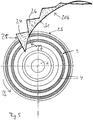
- FIG. 5 shows the further processing of the part 20b, the initial triangle 24 is supplied to the plate to be occupied 23 by means of a not known per se known feed head.
- the upper grain of the band is indicated in the drawing.
- the band is wound so that the front edge 25 of the initial triangle 24 presses parallel to the surface of the support portion 3 in the adhesive sausages 4 and thus forms the lower edge.
- the process of loading is timed, with the plate 23 being rotated under the belt but resting when it is put on.
- the supply of the belt 20b stops and the attached starting blade 24 is separated from the belt 20b by a cut. This cut is performed by a knife provided on the feed head parallel to the lower edge 25. His direction is through the broken line 27 (see also FIG. 4 ) indicated.
- the disc 23 placed on a corresponding holder continues to rotate one step in the direction of the arrow B before the band 20b rotates the next triangular lamella 26 on the plate 23 behind the latter previous seats.
- the drive of the band can be supported by a kind of gear whose teeth engage in the tooth gaps of the abrasive tape.
- the lamellae When all the lamellae are mounted, they are placed together in a further step by pressure from above to the plate before the fully occupied disc is removed and fed to a device which ensures the curing of the adhesive. In this way, the plate 23 is covered with lamellae whose three edges form an isosceles triangle whose corner forming the point is cut parallel to the opposite lower edge.
- the uncut edge 31 of the band 20b forms the inner edge of the triangular lamellae.
- the edge strip 22 is important for the cohesion of the triangular lamellae and for guiding the "serrated band" 20b. For this reason, it must also have a certain thickness, which is about 4 mm for the slats shown here a lower edge length of 40 mm. Because of the necessary severing of this edge strip 22, it also comes to the cut corner of the ansich triangular lamella.
- FIG. 6 Now a finished flap grinding wheel 28 is shown with the slats 29 cut in this way. It can be clearly seen that the upper edge 30 of the grinding surface no longer projects beyond the edge formed by the underside of the grinding lamellae.
Landscapes
- Engineering & Computer Science (AREA)
- Mechanical Engineering (AREA)
- Polishing Bodies And Polishing Tools (AREA)
Description
- Die vorliegende Erfindung betrifft ein Verfahren zum Herstellen einer Lamellenschleifscheibe mit einer Vielzahl von dreieckigen sich schindelartig überlappenden Schleiflamellen, die auf einen rotierend antreibbaren tellerförmigen Träger aufgeklebt sind, wobei die Schleiflamellen eine erste gerade Kante und eine daran angrenzende zweite gerade Kante aufweisen, wobei eine dritte gerade Kante vorhanden ist, die zumindest in ihrer Verlängerung sowohl die erste Kante als auch die zweite Kante schneidet.
- Solche Lamellenschleifscheiben sind in unterschiedlichen Ausführungsformen bekannt. Beispielsweise zeigt das
DE 295 10 727 U1 einen Schleifteller, auf dessen Trägerabschnitt ein ringförmiger Belag aus einzelnen Schleiflamellen aufgeklebt ist. In dieser Ausführungsform sind die Schleiflamellen trapezförmig ausgebildet und überlappen sich schindelartig. Es sind auch Lamellenschleifscheiben bekannt, deren schindelartig überlappende Schleiflamellen rechteckig geschnitten sind, was bei der Fertigung den Vorteil hat, dass sie ohne Verlust aus einem fortlaufenden Band geschnitten werden können. Mit diesen rechteckigeigen Lamellen lassen sich tellerförmige Träger vollautomatisch bestücken, wobei die Schleiflamellen einzeln von einem Band abgeschnitten und hintereinander auf dem Schleifteller angeordnet werden. Als Nachteil dieser Schleiflamellen ist jedoch bekannt, dass sie am Nabenabschnitt des Schleiftellers wegen der Überlappung zu einem starken Auftrag führen. Dadurch ist die Zahl der aufzubringenden Schleiflamellen und damit die Menge des im Aussenbereich der Schleifscheibe befindlichen Schleifbandes begrenzt. - Um das Problem des starken Auftragens zu lösen, ist aus
DE 200 06 127 U1 ein Schleifteller mit Schleiflamellen bekannt, die eine sichelartige Geometrie haben. Die nach Innen abnehmende Breite dieser Schleiflamellen reduziert das Material, das zu dem problematischen Auftrag führt. Da diese sichelartige Geometrie zwei parallele und vor allem gleichlange Kanten bietet, ist es auch möglich, diese speziellen Schleiflamellen ohne Verlust aus einem Band zu schneiden. Wegen der konkaven Innenkante ist es jedoch problematisch, die tellerförmigen Träger automatisiert mit diesen Schleiflamellen zu bestücken. - Das
US 2 907 147 A zeigt einen Schleifteller dessen Trägerbereich mit sich gleichförmig wiederholt überlappenden Schleiflamellen belegt ist, welche die Geometrie von Ringsegmenten aufweisen. Der Form des Trägerbereichs des Schleiftellers kann so gut gefolgt werden, wenngelich die Möglichkeit die Schleiflamellen ohne Verlust aus einem Band zu schneiden so aufgegeben ist. Um diesem Nachteil zu begegnen ist auch hier auf die Möglichkeit verwiesen, Schleiflamellen trapezförmig aus einem Band zu schneiden. - Aufgabe der Erfindung ist es nunmehr, ein verbessertes Verfahren zur Herstellung der Lamellenschleifscheiben vorzuschlagen, mit dem sich Lamellenschleifscheiben mit nur geringem Materialaufwand herstellen lassen.
- Diese Aufgabe wird durch das Verfahren nach Anspruch 1 gelöst. Vorteilhafte Ausführungsformen der Erfindung sind in den Unteransprüchen genannt.
- Ein Grundgedanke liegt zunächst in der Geometrie der Schleiflamellen, die im Wesentlichen ein Dreieck beschreibt. Dabei bedeutet "im Wesentlichen", dass ein oder sogar zwei der Spitzen des Dreieckes auch um ein kleines Stück abgeschnitten sein können, ohne dass es dem Merkmal der "Dreieckigkeit" Abbruch tut. Erfindungsgemäß wird der Dreieckigkeit genügt, solange die durch Abschneiden entstehenden Kanten kürzer sind, als die das Dreieck bildenden Kanten. Dabei können die Kanten der Dreiecke gegebenenfalls auch ein wenig gebogen oder gewellt ausgeführt werden.
- Mit diesen dreieckigen Schleiflamellen ergeben sich vielfältige Möglichkeiten, die Eigenschaften der Lamellenschleifscheibe durch die Belegung zu beeinflussen. Erfindungswesentlich ist mit anderen Worten also der Verlauf der dritten Kante, die, wenn auch bei gegebenenfalls abgeschnitteten Ecken nur in ihrer gedachten Verlängerung, die beiden anderen Kanten schneidet. Auch wenn die Kanten eine leicht geschwungene oder eine wellige Form aufweisen können, so ist es doch wegen der einfacheren Handhabung besonders vorteilhaft, wenn sie alle geradlinig ausgebildet sind.
- Es kann von Vorteil sein, die Schleiflamellen als komplette Dreiecke, insbesondere als rechtwinklige, gleichschenklige oder gleichseitige Dreiecke auszubilden. Bei einer wegen der besonders einfachen Herstellung bevorzugten Ausführungsform ist jedoch eine der Ecken, insbesondere die von der Außenkante und der Innenkante eingeschlossene Ecke, also die im Verhältnis zur Drehrichtung hinten liegende Ecke, um ein Stück abgeschnitten. Diese Ausführungsform wird in der Beispielsbeschreibung genauer erklärt werden.
- In Bezug zu der Schleifscheibe bildet die erste insbesondere gerade Kante eine Unterkante, die im späteren Fertigungsprozess auf den Trägerabschnitt aufgesetzt wird. Die daran angrenzende zweite Kante bildet insofern eine Außenkante, als sie im Außenbereich der Schleifscheibe zu liegen kommt und mit den anderen Lamellen die Außenkontur der Lamellenschleifscheibe bildet. Die Schleiflamellen haben eine dritte Kante, die als Innenkante zum Nabenabschnitt ausgerichtet ist. Erfindungsgemäß schneidet die Innenkante, zumindest in ihrer Verlängerung, sowohl die Unterkante als auch die Außenkante.
- In einer im Hinblick auf die gleichmäßige Belegung vorteilhaften Ausführungsform schließen die Unterkante und die Außenkante einer Schleiflamelle einen Winkel von 90° ein, wobei Unterkante und Außenkante ein gleichschenkliges Dreieck ausbilden können. Durch diese besondere Form wird ein Legewinkel ermöglicht, der zu einem günstigen Schleifverhalten und zu einer guten Zerspanung führt. Zudem ist die gerade Seite für eine Führung beim Legen der Lammelenschleifscheibe besonders gut geeignet. Diese Dreiecksform lässt sich dementsprechend gut verarbeiten.
- In einer anderen besonders einfach zu verarbeitenden Ausführungsform bilden die Lamellen gleichschenklige und dabei gegebenefalls gleichseitige Dreiecke aus, deren Unterkante auf dem tellerförmigen Träger aufliegt und deren der Unterkante gegenüberliegende Ecke vorzugsweise parallel zur Unterkante abgeschnitten ist. Diese Ausführungsform hat den Vorteil, dass sie als ein vorgeschnittenes Band aneinander hängender Dreiecke einer Beschickungsvorrichtung zugeführt werden kann, die den tellerförmigen Träger belegt. Dabei hängen die Dreiecke über eine gemeinsame Basis, die von einem Seitenstreifen des Bandes gebildet wird, zusammen. Beim Belegen wird zunächst das ankommende, vom Schleifmittel gebildete und vorgeschnittene Band mit seiner in diesem Falle abgeschrägten stirnseitigen Kante auf den abfallenden äußeren Trägerabschnitt des Trägers aufgesetzt und von dem dort vorhandenen Kleber gehalten. Nach dem Aufsetzen wird die zu dem Zeitpunkt noch vermittels des Seitenstreifens am Band hängende Lamelle abgeschnitten. Das Abtrennen der Lamelle erfolg vorteilhafterweise parallel zur Unterkante, so dass die abgeschnittene Ecke entsteht.
- Die erfindungsgemäß dreieckige Geometrie der Schleiflamellen führt zu einer Reihe von Vorteilen: Der erste wesentliche Vorteil liegt darin, dass sich die Schleiflamellen ohne Verlust aus einem fortlaufenden Band aus Schleifpapier oder aus Schleifgewebe schneiden lassen. Dabei wird eine Kante, vorteilhafterweise die Außenkante oder die Innenkante, von dem Band gebildet und braucht dementsprechend nicht geschnitten zu werden. Zudem ist es vorteilhaft, dass im Prinzip eine geringe Anzahl solcher erfindungsgemäßer Schleiflamellen ausreicht, um den ganzen Trägerabschnitt damit schindelartig überlappend zu belegen. Das kann zu einer Reduzierung der Kosten beitragen. Durch eine geringe Anzahl von Schleiflamellen ergibt sich auch ein geringer Anstellwinkel der Schleiflamellen, was zu einem besseren Schleifverhalten führt und eine flache Bauweise des Schleiftellers begünstigt. Allerdings verlangen leistungsstarke Schleifscheiben eine große Anzahl von Lamellen, die viel Material in den Aussenbereich bringen.
- Entsprechend ist es von Vorteil, eine große Anzahl von Schleiflamellen auf den Träger aufzubringen, was mit der Dreieckform ebenfalls problemlos möglich ist, da dreieckige Schleiflamellen im Inneren nur zu einem verhältnismäßig geringen Auftrag führen. Wegen ihrer nach Innen gerichteten Spitzen ermöglicht es die dreieckige Lamellenform also, eine hohe Anzahl von Lamellen aufzubringen, ohne dass die Lamellen sich zur Bohrung hin aufbauen. Da entsprechend mehr Schleifmaterial vorhanden ist, führt eine große Anzahl von Lamellen zu einer größeren Standzeit des Werkzeugs. Dabei bedeutet "große Anzahl", dass der Träger mehr als 50, insbesondere mehr als 70 Schleiflamellen oder sogar mehr als 100 Schleiflamellen trägt. Bekanntermaßen kann die Neigung der für das Aufbringen der Lamellen vorgesehenen Außenfläche des Trägers entsprechend des Auftrages durch die große Zahl von Schleiflamellen mehr oder weniger stark geneigt sein.
- Ein weiterer Vorteil ist, dass die Überdeckung bei einem mit den dreieckigen Schleiflamellen belegten Schleifteller im Randbereich am größten ist, wo die höchsten Geschwindigkeiten auftreten und wo die bevorzugte Arbeitszone liegt. Somit steht an der am stärksten beanspruchten Stelle der Schleifscheibe das meiste Material zur Verfügung, während Innen, wo nur ein geringer Beitrag zur Schleifabtragung geleistet wird, weniger Schleifmaterial vorhanden ist. Auch dadurch wird die Standzeit der Lamellenschleifscheibe erhöht. Mit der erfindungsgemäßen Belegung wird somit gegenüber einer herkömmlichen mit rechteckigen Lamellen bestückten Lamellenschleifscheibe verhältnismäßig viel Schleifmaterial im Außenbereich der Scheibe konzentriert. Dadurch, dass das Schleifmaterial an der Stelle konzentriert wird, wo es benötigt wird, kann die Zerspanungsleistung erhöht werden.
- Ein weiterer Vorteil ist, dass sich durch die Belegung mit den Dreiecken eine über die Schleiffläche gleichmäßige Verdichtung des Materials einstellt. Damit ist ein Eingriff der Lamellenschleifscheibe mit der gesamten Schleiffläche auf dem Werkstück begünstigt, was zu einer besonders komfortablen und kontrollierten Handhabung und damit zu einem präzisen Schliff führt.
- Vorteilhaft ist vor allem auch, dass sich über die Kantenlänge der Schleiflamellen, über den Winkel der Aufbringung und über die Belegungsdichte eine Vielzahl von Eigenschaften einstellen lassen. So können über diese Faktoren unterschiedliche Arten von Lamellenschleifscheiben, von flachen Scheiben für das Schleifen mit großer Zerspanung bis hin zu topfartigen oder trichterförmigen Scheiben generiert werden. Durch Variation der Abmessungen, der Anzahl und der Lagewinkel der dreieckigen Schleiflamellen lässt sich eine große Bandbreite von verhältnismäßig flachen bis hin zu hohen topfartigen Lamellenschleifscheiben mit großem Lamellenüberstand herstellen.
- Bei topfartigen Scheiben sind die Schleiflamellen derart auf den Träger aufgeklebt, dass die Außenkontur sich zur Schleiffläche hin trichterförmig öffnet und der äußere Rand der Schleiffläche den von der Unterseite der Schleiflamellen gebildeten Rand und auch den Rand des Trägers überragt. Damit ist eine Schleiffläche mit einem besonders dünnen und mit ausreichend Schleifmaterial belegten Rand geschaffen. Solche Schleifscheiben eignen sich besonders für das Schleifen in Ecken. Durch den überstehenden Rand, den die Schleiflamellen bilden, wird auch das zu schleifende Werkstück vor der Kante des tellerförmigen Trägers geschützt. Zudem ist mit solchen topfartigen Scheiben ein besonders guter Flächenschliff möglich, da sie über die gesamte Fläche ausreichend Schleifmaterial bei homogene Dichte gewährleisten. Ein weiterer Vorteil der topfartigen Lamellenschleifscheibe ist, dass sie eine am Boden des Trichters versenkte Aufnahme hat. Bei der topfartigen Lamellenschleifscheibe muss die Lage des Flansches nicht durch die Geometrie des Trägers abgesenkt werden. Stattdessen verschwindet der Flansch durch die Höhe der aufgebrachten Lamellen. Auch diese Tatsache führt dazu, dass sich eine solche Lamellenschleifscheibe gut für den Flächenschliff eignet.
- Nachfolgend wird die Erfindung anhand der
Figuren 1 bis 6 näher erklärt. Dabei zeigen - Figur 1:
- einen Schleifteller mit einer dreieckigen Schleiflamelle,
- Figur 2:
- eine flache Lamellenschleifscheibe,
- Figur 3:
- eine topfförmige Lamellenschleifscheibe,
- Figur 4:
- ein geschnittenes Band,
- Figur 5:
- das Belegen eines Schleiftellers und
- Figur 6:
- eine Lamellenschleifscheibe
- In
Figur 1 ist ein Träger 1 in Form eines runden Tellers aus Kunststoff gezeigt, der in der Mitte eine genormte, die Nabe bildende Bohrung 2 hat. Diese genormte Bohrung ist für den Einsatz eines Befestigungselementes zur Befestigung der Arbeitsspindel einer Arbeitsmaschine geeignet. Auch wenn beliebige Tellerformen und Größen denkbar sind, so handelt es sich im vorliegenden Fall um einen Träger mit einem Durchmesser von 115 mm. Statt aus Kunststoff, können auch Träger aus Faserstoff, Holz oder Metall eingesetzt werden. Der Träger 1 weist einen ringförmigen, konisch nach Außen abfallenden Trägerabschnitt 3 auf, der auf der Achse zentriert ist. Im vorliegenden Beispiel beträgt der Winkel des Konus etwa 12°. Je nach dem, können auch Winkel zwischen 10° und 30° zum Einsatz kommen. Auf dem Trägerabschnitt 3 werden während des Fertigungsverfahrens zwei konzentrische Würste 4 aus Klebstoff aufgebracht, mit dem die einzelnen Schleiflamellen aufgeklebt werden. Das automatische Aufbringen der Würste 4 ist an sich bekannt und geschieht beispielsweise in einem ersten Fertigungsschritt, nachdem der rohe Teller ergriffen und auf einer Halterung platziert wurde. - Nach dem Aufbringen des Klebers wird in einem weiteren Fertigungsschritt eine Schleiflamelle 5, die erfindungsgemäß dreieckig ist, auf den Trägerabschnitt 3 mit der Unterkante 6 aufgesetzt und mittels der Würste 4 verklebt. Die Schleiflamelle 5 hat eine an die Unterkante 6 angrenzende Außenkante 7. In diesem Fall sind Unterkante 6 und Außenkante 7 jeweils 30 mm lang und im rechten Winkel angeordnet. Die Schleiflamelle 5 ist aus einem Schleifmittel-Band von 30 mm Breite geschnitten. Erfindungsgemäß ist die Schleiflamelle 5 dreieckig, wobei die Innenkante 8 als dritte Kante die Unterkante 6 und die Außenkante 7 schneidet. Die Unterkante liegt in Drehrichtung der Lamellenschleifscheibe vorne. Die Schleiflamelle 5 hat somit im vorliegenden Fall die Geometrie eines rechtwinkligen und gleichschenkligen Dreiecks. Dieses Dreieck ist derart auf den Träger 1 aufgeklebt, dass die Mittelsenkrechte 9 der Außenkante 7 radial angeordnet ist. Der durch die Spitze des Dreiecks verlaufende Radius 10 ist damit gegenüber der Mittelsenkrechten 10 um 23° (siehe Winkel α) geneigt.
- In
Figur 2 ist eine mit 75 solcher dreieckiger Schleiflamellen 5 und damit komplett belegte Lamellenschleifscheibe 11 gezeigt, die für die Drehung in Pfeilrichtung geeignet ist. Zu erkennen ist die schindelartige Überlappung der Schleiflamellen 5. Das Belegen des Trägers mit den Schleiflamellen 5 kann automatisch geschehen, wobei die dreieckigen Schleiflamellen 5 von einem als aufgerolltes Band vorliegenden Schleifpapier oder aus Schleifgewebe, also einem Schleifmittel auf Unterlage, mittels eines Schneidwerkzeuges abgeschnitten wurden. Wie die Seitenansicht inFigur 2b zeigt, sind die Schleiflamellen derart auf den Träger 1 aufgeklebt, dass die Außenkontur 12 eine Taille aufweist, wobei der Rand 13 der Schleiffläche 14 zumindest nahezu denselben Durchmesser wie der von der Unterseite der Schleiflamellen gebildete Rand 15 aufweist. Deutlich zu erkennen ist auch die ebene Schleiffläche 14. Ersichtlich ermöglicht es die dreieckige Lamellenform, eine hohe Zahl an Lamellen aufzubringen, ohne dass die Lamellen sich zur Bohrung 2 hin aufbauen. - In
Figur 3 ist eine topfförmige Lamellenschleifscheibe 16 mit 75 Lamellen 17 perspektivisch gezeigt. Die Lamellen 17 haben die Form eines rechtwinkligen Dreiecks mit einer Unterkante von 30 mm Länge und einer Außenkante von 40 mm Länge. Deutlich zu erkennen ist, dass der Rand 18 der Schleiffläche über den von der Unterseite der Schleiflamellen gebildeten Rand 19 übersteht und sich eine hoch aufbauende Trichter- oder Topfform ergibt. Die vorgesehene Drehrichtung ist durch den Pfeil gekennzeichnet. -
Figur 4 zeigt ein Band 20 aus bekanntem Schleifmaterial, in das beispielsweise mit einer nicht gezeigten Messerwalze ein in Dreieckslinie verlaufender Schlitz 21 eingeschnitten wurde. Neben dem derart geschlitzten mittleren Bereich weist das Band links und rechts Randstreifen 22 aus durchgängigem Material auf. Es kann sich dabei um ein quasi Endlosband handeln, das vorkonfektioniert auf einer Rolle aufgewickelt ist und in Richtung des Pfeiles A der Vorrichtung zum Belegen eines Schleiftellers bewegt wird. Der geschlitzte Bereich kann aber auch kurz vor dem Belegen eines Tellers in ein bis dahin ungeschlitztes Band eingebracht werden. - Das durch den Schlitz 21 zweigeteilte Band 20 wird ab einer bestimmten Stelle in seine beiden Streifen 20a und 20b getrennt, wobei jeder der Streifen 20a und 20b einer gesonderten Weiterverarbeitung zugeführt wird. Jeder der Streifen 20a und 20b weist quasi als Basis den jeweiligen Randsreifen mit den sich darüber erhebenden Dreiecken auf.
-
Figur 5 zeigt die weitere Verarbeitung des Teiles 20b, dessen Anfangsdreieck 24 vermittels eines nicht aber an sich bekannten dargestellten Beschickungskopfes dem zu belegenden Teller 23 zugeführt wird. Die oben liegende Körnung des Bandes ist zeichnerisch angedeutet. Zunächst wird das Band so gewunden, dass sich die vorne liegende Kante 25 des Anfangsdreieck 24 parallel zur Oberfläche des Trägerabschnittes 3 in die Kleberwürste 4 drückt und damit die Unterkante bildet. Der Prozess der Beschickung ist getaktet, wobei der Teller 23 unter dem Band gedreht wird, beim Aufsetzen jedoch still steht. Nach dem Aufsetzen stoppt die Zufuhr des Bandes 20b und die aufgesetzte Anfangslamelle 24 wird durch einen Schnitt von dem Band 20b getrennt. Dieser Schnitt wird durch ein am Beschickungskopf vorgesehenes Messer parallel zur Unterkante 25 durchgeführt. Seine Richtung ist durch die unterbrochene Linie 27 (siehe auchFigur 4 ) angedeutet. Nach dem Schnitt rotiert die auf einem entsprechenden Halter platzierte Scheibe 23 um einen Schritt in Richtung des Pfeiles B weiter, bevor das Band 20b die nächste Dreieckslamelle 26 auf dem Teller 23 hinter die vorhergehende setzt. Der Antrieb des Bandes kann dabei von einer Art Zahnrad unterstützt werden, dessen Zähne in die Zahnlücken des Schleifmittelbandes eingreift. - Wenn alle Lamellen aufgesetzt sind, werden sie in einem weiteren Schritt gemeinsam durch Druck von oben an den Teller angelegt, bevor die vollständig belegte Scheibe entnommen und einer Vorrichtung zugeführt wird, die das Aushärten des Klebers gewährleistet. Auf diese Weise ist der Teller 23 mit Lamellen belegt, deren drei Kanten ein gleichschenkliges Dreieck ausbilden, dessen die Spitze bildende Ecke parallel zur gegenüberliegenden Unterkante abgeschnitten ist.
- In dieser Ausführungsform, bildet der nicht geschnittene Rand 31 des Bandes 20b die Innenkante der Dreieckslamellen. Es ist ersichtlich, dass der Randstreifen 22 für den Zusammenhalt der Dreieckslamellen und zur Führung des "Zackenbandes" 20b von Bedeutung ist. Aus diesem Grund muss er auch eine gewisse Stärke aufweisen, die bei den hier gezeigten Lamellen einer Unterkantenlänge von 40 mm etwa 4 mm beträgt. Wegen des notwendigen Durchtrennens dieses Randstreifens 22 kommt es auch zu der abgeschnittenen Ecke der ansich dreieckigen Lamelle.
- In
Figur 6 ist nunmehr eine fertige Lamellenschleifscheibe 28 mit den auf diese Art geschnittenen Lamellen 29 gezeigt. Deutlich zu erkennen ist, dass der obere Rand 30 der Schleiffläche nicht mehr über den von der Unterseite der Schleiflamellen gebildeten Rand übersteht.
Claims (6)
- Verfahren zum Herstellen einer Lamellenschleifscheibe mit einer Vielzahl von dreieckigen sich schindelartig überlappenden Schleiflamellen (5), die auf einen rotierend antreibbaren tellerförmigen Träger (1) aufgeklebt sind, wobei die Schleiflamellen (5) eine erste gerade Kante (6) und eine daran angrenzende zweite gerade Kante (7) aufweisen, wobei eine dritte gerade Kante (8) vorhanden ist, die zumindest in ihrer Verlängerung sowohl die erste Kante (6) als auch die zweite Kante (7) schneidet,
dadurch gekennzeichnet,
dass die Schleiflamellen (5) als eine Vielzahl von Schleiflamellen ohne Verlust aus einem fortlaufenden Band (20) eines Schleifmittels aus Schleifpapier oder Schleifgewebe geschnitten werden,
dass das Band (20) des Schleifmittels so vorgeschnitten wird, dass der Schnitt einen in einer Dreieckslinie verlaufenden Schlitz (21) bewirkt, der das Band (20) in zwei Streifen (20a) und (20b) auftrennt, wobei ein Streifen (20b) über ihre Basis zusammenhängende Dreieckslamellen aufweist und einer Vorrichtung zum Bestücken zugeführt wird,
dass der Streifen (20b) derart gewunden wird, dass die erste Dreieckslamelle (24) des Streifens (20b) mit der vorne liegenden Kante (25) auf den Trägerabschnitt (3) des Trägers (1,23) aufgesetzt und von dort aufgebrachtem Kleber (4) gehalten wird,
dass die aufgesetzte erste Dreieckslamelle (24) durch einen Schnitt (27) von dem Streifen (20b) getrennt wird und
dass nach dem Trennen der Träger (23) um einen Schritt weiter bewegt wird in die Position zum Aufsetzen der nächsten Lamelle (26). - Verfahren nach Anspruch 1,
dadurch gekennzeichnet,
dass die drei Kanten (6,7,8) ein gleichschenkliges Dreieck ausbilden, dessen die Spitze bildende Ecke parallel zur gegenüberliegenden Unterkante abgeschnitten ist. - Verfahren nach Anspruch 1 oder 2,
dadurch gekennzeichnet,
dass die erste Kante eine Unterkante (6, 25) bildet, die daran angrenzende zweite gerade Kante eine Außenkante (7) bildet, und die dritte Kante eine Innenkante (8,31) bildet, wobei die Außenkanten (7) der Schleiflamellen (5) die Außenkontur (12) der Lamellenschleifscheibe (11) bilden.. - Verfahren nach einem der vorherigen Ansprüche,
dadurch gekennzeichnet,
dass die Schleiflamellen (24,26) derart auf den Träger (1,23) aufgeklebt werden, dass die Außenkontur (12) sich trichterförmig zur Schleiffläche (14) hin öffnet und der Rand der Schleiffläche (14) den von der Unterseite der Schleiflamellen gebildeten Rand (15) und auch den Rand des Trägers (23) überragt. - Verfahren nach einem der vorherigen Ansprüche,
dadurch gekennzeichnet,
dass die Schleiflamellen (24,26) derart auf den Träger (1,23) aufgeklebt werden, dass die Außenkontur (12) tailliert ist und der Rand der Schleiffläche zumindest nahezu denselben Durchmesser, wie der von der Unterseite der Schleiflamellen gebildete Rand aufweist. - Verfahren nach Anspruch 1,
dadurch gekennzeichnet,
dass jeder der Streifen einer gesonderten Weiterverarbeitung zugeführt wird.
Priority Applications (1)
| Application Number | Priority Date | Filing Date | Title |
|---|---|---|---|
| PL08707032T PL2099586T3 (pl) | 2007-01-12 | 2008-01-14 | Ściernica listkowa |
Applications Claiming Priority (2)
| Application Number | Priority Date | Filing Date | Title |
|---|---|---|---|
| DE102007002643A DE102007002643A1 (de) | 2007-01-12 | 2007-01-12 | Lamellenschleifscheibe |
| PCT/EP2008/000228 WO2008083994A1 (de) | 2007-01-12 | 2008-01-14 | Lamellenschleifscheibe |
Publications (2)
| Publication Number | Publication Date |
|---|---|
| EP2099586A1 EP2099586A1 (de) | 2009-09-16 |
| EP2099586B1 true EP2099586B1 (de) | 2017-03-29 |
Family
ID=39259672
Family Applications (1)
| Application Number | Title | Priority Date | Filing Date |
|---|---|---|---|
| EP08707032.2A Not-in-force EP2099586B1 (de) | 2007-01-12 | 2008-01-14 | Lamellenschleifscheibe |
Country Status (6)
| Country | Link |
|---|---|
| EP (1) | EP2099586B1 (de) |
| CN (1) | CN101578158B (de) |
| DE (2) | DE102007002643A1 (de) |
| ES (1) | ES2629984T3 (de) |
| PL (1) | PL2099586T3 (de) |
| WO (1) | WO2008083994A1 (de) |
Families Citing this family (3)
| Publication number | Priority date | Publication date | Assignee | Title |
|---|---|---|---|---|
| DE102009054696A1 (de) | 2009-12-15 | 2011-06-16 | August Rüggeberg Gmbh & Co. Kg | Fächer-Schleifscheibe für den Einsatz an stationären Schleifmaschinen |
| ES2742151T3 (es) * | 2015-08-21 | 2020-02-13 | Rueggeberg August Gmbh & Co Kg | Herramienta abrasiva y procedimiento para fabricar una herramienta abrasiva de este tipo |
| CN109202755A (zh) * | 2018-10-30 | 2019-01-15 | 临邑禹王植物蛋白有限公司 | 一种波浪形树脂切割片及其模具和制备方法 |
Family Cites Families (10)
| Publication number | Priority date | Publication date | Assignee | Title |
|---|---|---|---|---|
| GB624928A (en) * | 1942-03-16 | 1949-06-20 | Minnesota Mining & Mfg | Improvements in or relating to flexible abrasive articles in disc form |
| US2907147A (en) * | 1957-12-23 | 1959-10-06 | F L & J C Codman Company | Radial face rotary buffing element |
| CN2102822U (zh) * | 1990-12-26 | 1992-04-29 | 程东利 | 多用途叶片式砂布轮 |
| DE29510727U1 (de) | 1995-01-24 | 1995-08-31 | Lukas-Erzett Vereinigte Schleif- und Fräswerkzeugfabriken GmbH & Co KG, 51766 Engelskirchen | Werkzeug, insbesondere Schleif- oder Polierteller |
| DE19604540A1 (de) * | 1996-02-08 | 1997-08-14 | Leo Klapperich | Oberflächen-Bearbeitungsvorrichtung |
| DE10015418C2 (de) * | 2000-03-28 | 2001-04-19 | Eisenblaetter Gerd Gmbh | Schleifwerkzeug und Verfahren zu dessen Herstellung |
| DE20006127U1 (de) | 2000-04-03 | 2000-07-06 | Lukas-Erzett Vereinigte Schleif- und Fräswerkzeugfabriken GmbH & Co KG, 51766 Engelskirchen | Schleiflamelle und Schleifteller mit einer Mehrzahl von solchen |
| CN2452681Y (zh) * | 2000-12-13 | 2001-10-10 | 陈显达 | 砂布轮的砂布组合结构 |
| US6945863B1 (en) * | 2004-08-19 | 2005-09-20 | Weiler Corporation | Rotary finishing disc |
| DE102006024015A1 (de) * | 2006-05-23 | 2007-11-29 | August Rüggeberg Gmbh & Co. Kg | Fächer-Schleifscheibe |
-
2007
- 2007-01-12 DE DE102007002643A patent/DE102007002643A1/de not_active Withdrawn
-
2008
- 2008-01-14 PL PL08707032T patent/PL2099586T3/pl unknown
- 2008-01-14 CN CN2008800021903A patent/CN101578158B/zh not_active Expired - Fee Related
- 2008-01-14 ES ES08707032.2T patent/ES2629984T3/es active Active
- 2008-01-14 WO PCT/EP2008/000228 patent/WO2008083994A1/de not_active Ceased
- 2008-01-14 EP EP08707032.2A patent/EP2099586B1/de not_active Not-in-force
- 2008-03-12 DE DE102008013961A patent/DE102008013961B3/de not_active Expired - Fee Related
Non-Patent Citations (1)
| Title |
|---|
| None * |
Also Published As
| Publication number | Publication date |
|---|---|
| DE102007002643A1 (de) | 2008-07-17 |
| DE102008013961B3 (de) | 2009-04-09 |
| CN101578158A (zh) | 2009-11-11 |
| CN101578158B (zh) | 2012-11-28 |
| WO2008083994A1 (de) | 2008-07-17 |
| EP2099586A1 (de) | 2009-09-16 |
| ES2629984T3 (es) | 2017-08-17 |
| PL2099586T3 (pl) | 2017-10-31 |
Similar Documents
| Publication | Publication Date | Title |
|---|---|---|
| DE19853550C1 (de) | Fächerschleifscheibe | |
| DE3700250C2 (de) | ||
| DE4300057B4 (de) | Mit einem Schleifmittel beschichtetes Erzeugnis und Verfahren zu dessen Herstellung | |
| DE3883437T2 (de) | Methode und Vorrichtung zur Erzeugung von Schneidkanten. | |
| DE3609251C2 (de) | ||
| DE1502701A1 (de) | Schleifschneidwerkzeuge,z.B. Saegen | |
| EP2835220B1 (de) | Abrichtwerkzeug sowie ein Verfahren zu dessen Herstellung | |
| EP3681675B1 (de) | Schleifartikel | |
| CH359376A (de) | Schleifvorrichtung, Verwendung der Schleifvorrichtung und Verfahren zu ihrer Herstellung | |
| DE102008013961B3 (de) | Verfahren zur Herstellung einer Lamellenschleifscheibe | |
| DE3114687A1 (de) | Schneidblatt | |
| DE69211137T2 (de) | Mit einem Vielpunktschnittwerkzeug, planiertes, beschichtetes Schleifmittel | |
| DE2852484A1 (de) | Feldhaecksler | |
| EP2170558B1 (de) | Schleifmittel zum behandeln von oberflächen | |
| EP3651936B1 (de) | Fächerschleifscheibe für einen winkelschleifer | |
| DE69225016T2 (de) | Herstellung von Verbundglasscheiben | |
| DE2719402C2 (de) | ||
| DE2600220C2 (de) | Vorrichtung zum Auftrennen von Polschlingen | |
| DE69908734T2 (de) | Apparat zum Schärfen von Schneidemesser | |
| DE4314008C2 (de) | Verfahren und Vorrichtung zur Herstellung von Stahlfasern | |
| EP1378373B1 (de) | Vorrichtung zum Bearbeiten von Seitenkanten von blattförmigen Bedruckstoffen | |
| EP3325216A1 (de) | Schleifscheibe mit einem vlies-stützteller | |
| DE60213652T2 (de) | Vorrichtung zur verwendung beim ablösen von tapeten | |
| DE102011050130A1 (de) | Schleiflamelle | |
| DE102009041881B4 (de) | Buchbindeverfahren sowie Buchbindevorrichtung |
Legal Events
| Date | Code | Title | Description |
|---|---|---|---|
| PUAI | Public reference made under article 153(3) epc to a published international application that has entered the european phase |
Free format text: ORIGINAL CODE: 0009012 |
|
| 17P | Request for examination filed |
Effective date: 20090520 |
|
| AK | Designated contracting states |
Kind code of ref document: A1 Designated state(s): AT BE BG CH CY CZ DE DK EE ES FI FR GB GR HR HU IE IS IT LI LT LU LV MC MT NL NO PL PT RO SE SI SK TR |
|
| 17Q | First examination report despatched |
Effective date: 20091014 |
|
| DAX | Request for extension of the european patent (deleted) | ||
| GRAP | Despatch of communication of intention to grant a patent |
Free format text: ORIGINAL CODE: EPIDOSNIGR1 |
|
| INTG | Intention to grant announced |
Effective date: 20161216 |
|
| GRAS | Grant fee paid |
Free format text: ORIGINAL CODE: EPIDOSNIGR3 |
|
| GRAA | (expected) grant |
Free format text: ORIGINAL CODE: 0009210 |
|
| AK | Designated contracting states |
Kind code of ref document: B1 Designated state(s): AT BE BG CH CY CZ DE DK EE ES FI FR GB GR HR HU IE IS IT LI LT LU LV MC MT NL NO PL PT RO SE SI SK TR |
|
| REG | Reference to a national code |
Ref country code: GB Ref legal event code: FG4D Free format text: NOT ENGLISH |
|
| REG | Reference to a national code |
Ref country code: CH Ref legal event code: EP |
|
| REG | Reference to a national code |
Ref country code: AT Ref legal event code: REF Ref document number: 879290 Country of ref document: AT Kind code of ref document: T Effective date: 20170415 |
|
| REG | Reference to a national code |
Ref country code: IE Ref legal event code: FG4D Free format text: LANGUAGE OF EP DOCUMENT: GERMAN |
|
| REG | Reference to a national code |
Ref country code: DE Ref legal event code: R096 Ref document number: 502008015161 Country of ref document: DE |
|
| PG25 | Lapsed in a contracting state [announced via postgrant information from national office to epo] |
Ref country code: HR Free format text: LAPSE BECAUSE OF FAILURE TO SUBMIT A TRANSLATION OF THE DESCRIPTION OR TO PAY THE FEE WITHIN THE PRESCRIBED TIME-LIMIT Effective date: 20170329 Ref country code: GR Free format text: LAPSE BECAUSE OF FAILURE TO SUBMIT A TRANSLATION OF THE DESCRIPTION OR TO PAY THE FEE WITHIN THE PRESCRIBED TIME-LIMIT Effective date: 20170630 Ref country code: FI Free format text: LAPSE BECAUSE OF FAILURE TO SUBMIT A TRANSLATION OF THE DESCRIPTION OR TO PAY THE FEE WITHIN THE PRESCRIBED TIME-LIMIT Effective date: 20170329 Ref country code: NO Free format text: LAPSE BECAUSE OF FAILURE TO SUBMIT A TRANSLATION OF THE DESCRIPTION OR TO PAY THE FEE WITHIN THE PRESCRIBED TIME-LIMIT Effective date: 20170629 Ref country code: LT Free format text: LAPSE BECAUSE OF FAILURE TO SUBMIT A TRANSLATION OF THE DESCRIPTION OR TO PAY THE FEE WITHIN THE PRESCRIBED TIME-LIMIT Effective date: 20170329 |
|
| REG | Reference to a national code |
Ref country code: NL Ref legal event code: MP Effective date: 20170329 |
|
| REG | Reference to a national code |
Ref country code: ES Ref legal event code: FG2A Ref document number: 2629984 Country of ref document: ES Kind code of ref document: T3 Effective date: 20170817 |
|
| PG25 | Lapsed in a contracting state [announced via postgrant information from national office to epo] |
Ref country code: SE Free format text: LAPSE BECAUSE OF FAILURE TO SUBMIT A TRANSLATION OF THE DESCRIPTION OR TO PAY THE FEE WITHIN THE PRESCRIBED TIME-LIMIT Effective date: 20170329 Ref country code: LV Free format text: LAPSE BECAUSE OF FAILURE TO SUBMIT A TRANSLATION OF THE DESCRIPTION OR TO PAY THE FEE WITHIN THE PRESCRIBED TIME-LIMIT Effective date: 20170329 Ref country code: BG Free format text: LAPSE BECAUSE OF FAILURE TO SUBMIT A TRANSLATION OF THE DESCRIPTION OR TO PAY THE FEE WITHIN THE PRESCRIBED TIME-LIMIT Effective date: 20170629 |
|
| PG25 | Lapsed in a contracting state [announced via postgrant information from national office to epo] |
Ref country code: NL Free format text: LAPSE BECAUSE OF FAILURE TO SUBMIT A TRANSLATION OF THE DESCRIPTION OR TO PAY THE FEE WITHIN THE PRESCRIBED TIME-LIMIT Effective date: 20170329 |
|
| PG25 | Lapsed in a contracting state [announced via postgrant information from national office to epo] |
Ref country code: SK Free format text: LAPSE BECAUSE OF FAILURE TO SUBMIT A TRANSLATION OF THE DESCRIPTION OR TO PAY THE FEE WITHIN THE PRESCRIBED TIME-LIMIT Effective date: 20170329 Ref country code: EE Free format text: LAPSE BECAUSE OF FAILURE TO SUBMIT A TRANSLATION OF THE DESCRIPTION OR TO PAY THE FEE WITHIN THE PRESCRIBED TIME-LIMIT Effective date: 20170329 Ref country code: RO Free format text: LAPSE BECAUSE OF FAILURE TO SUBMIT A TRANSLATION OF THE DESCRIPTION OR TO PAY THE FEE WITHIN THE PRESCRIBED TIME-LIMIT Effective date: 20170329 |
|
| PG25 | Lapsed in a contracting state [announced via postgrant information from national office to epo] |
Ref country code: PT Free format text: LAPSE BECAUSE OF FAILURE TO SUBMIT A TRANSLATION OF THE DESCRIPTION OR TO PAY THE FEE WITHIN THE PRESCRIBED TIME-LIMIT Effective date: 20170731 Ref country code: IS Free format text: LAPSE BECAUSE OF FAILURE TO SUBMIT A TRANSLATION OF THE DESCRIPTION OR TO PAY THE FEE WITHIN THE PRESCRIBED TIME-LIMIT Effective date: 20170729 |
|
| REG | Reference to a national code |
Ref country code: DE Ref legal event code: R097 Ref document number: 502008015161 Country of ref document: DE |
|
| PG25 | Lapsed in a contracting state [announced via postgrant information from national office to epo] |
Ref country code: DK Free format text: LAPSE BECAUSE OF FAILURE TO SUBMIT A TRANSLATION OF THE DESCRIPTION OR TO PAY THE FEE WITHIN THE PRESCRIBED TIME-LIMIT Effective date: 20170329 |
|
| PLBE | No opposition filed within time limit |
Free format text: ORIGINAL CODE: 0009261 |
|
| STAA | Information on the status of an ep patent application or granted ep patent |
Free format text: STATUS: NO OPPOSITION FILED WITHIN TIME LIMIT |
|
| 26N | No opposition filed |
Effective date: 20180103 |
|
| PG25 | Lapsed in a contracting state [announced via postgrant information from national office to epo] |
Ref country code: SI Free format text: LAPSE BECAUSE OF FAILURE TO SUBMIT A TRANSLATION OF THE DESCRIPTION OR TO PAY THE FEE WITHIN THE PRESCRIBED TIME-LIMIT Effective date: 20170329 |
|
| REG | Reference to a national code |
Ref country code: CH Ref legal event code: PL |
|
| GBPC | Gb: european patent ceased through non-payment of renewal fee |
Effective date: 20180114 |
|
| PG25 | Lapsed in a contracting state [announced via postgrant information from national office to epo] |
Ref country code: MT Free format text: LAPSE BECAUSE OF FAILURE TO SUBMIT A TRANSLATION OF THE DESCRIPTION OR TO PAY THE FEE WITHIN THE PRESCRIBED TIME-LIMIT Effective date: 20170329 |
|
| PG25 | Lapsed in a contracting state [announced via postgrant information from national office to epo] |
Ref country code: FR Free format text: LAPSE BECAUSE OF NON-PAYMENT OF DUE FEES Effective date: 20180131 Ref country code: LU Free format text: LAPSE BECAUSE OF NON-PAYMENT OF DUE FEES Effective date: 20180114 |
|
| REG | Reference to a national code |
Ref country code: IE Ref legal event code: MM4A |
|
| REG | Reference to a national code |
Ref country code: FR Ref legal event code: ST Effective date: 20180928 |
|
| REG | Reference to a national code |
Ref country code: BE Ref legal event code: MM Effective date: 20180131 |
|
| PG25 | Lapsed in a contracting state [announced via postgrant information from national office to epo] |
Ref country code: LI Free format text: LAPSE BECAUSE OF NON-PAYMENT OF DUE FEES Effective date: 20180131 Ref country code: CH Free format text: LAPSE BECAUSE OF NON-PAYMENT OF DUE FEES Effective date: 20180131 Ref country code: GB Free format text: LAPSE BECAUSE OF NON-PAYMENT OF DUE FEES Effective date: 20180114 Ref country code: BE Free format text: LAPSE BECAUSE OF NON-PAYMENT OF DUE FEES Effective date: 20180131 |
|
| PG25 | Lapsed in a contracting state [announced via postgrant information from national office to epo] |
Ref country code: IE Free format text: LAPSE BECAUSE OF NON-PAYMENT OF DUE FEES Effective date: 20180114 |
|
| PG25 | Lapsed in a contracting state [announced via postgrant information from national office to epo] |
Ref country code: IT Free format text: LAPSE BECAUSE OF NON-PAYMENT OF DUE FEES Effective date: 20180114 |
|
| REG | Reference to a national code |
Ref country code: AT Ref legal event code: MM01 Ref document number: 879290 Country of ref document: AT Kind code of ref document: T Effective date: 20180114 |
|
| PG25 | Lapsed in a contracting state [announced via postgrant information from national office to epo] |
Ref country code: AT Free format text: LAPSE BECAUSE OF NON-PAYMENT OF DUE FEES Effective date: 20180114 |
|
| PGFP | Annual fee paid to national office [announced via postgrant information from national office to epo] |
Ref country code: PL Payment date: 20190104 Year of fee payment: 12 Ref country code: DE Payment date: 20190326 Year of fee payment: 12 Ref country code: CZ Payment date: 20190104 Year of fee payment: 12 |
|
| PG25 | Lapsed in a contracting state [announced via postgrant information from national office to epo] |
Ref country code: MC Free format text: LAPSE BECAUSE OF FAILURE TO SUBMIT A TRANSLATION OF THE DESCRIPTION OR TO PAY THE FEE WITHIN THE PRESCRIBED TIME-LIMIT Effective date: 20170329 |
|
| REG | Reference to a national code |
Ref country code: ES Ref legal event code: FD2A Effective date: 20190730 |
|
| PG25 | Lapsed in a contracting state [announced via postgrant information from national office to epo] |
Ref country code: ES Free format text: LAPSE BECAUSE OF NON-PAYMENT OF DUE FEES Effective date: 20180115 |
|
| PG25 | Lapsed in a contracting state [announced via postgrant information from national office to epo] |
Ref country code: TR Free format text: LAPSE BECAUSE OF FAILURE TO SUBMIT A TRANSLATION OF THE DESCRIPTION OR TO PAY THE FEE WITHIN THE PRESCRIBED TIME-LIMIT Effective date: 20170329 |
|
| PG25 | Lapsed in a contracting state [announced via postgrant information from national office to epo] |
Ref country code: HU Free format text: LAPSE BECAUSE OF FAILURE TO SUBMIT A TRANSLATION OF THE DESCRIPTION OR TO PAY THE FEE WITHIN THE PRESCRIBED TIME-LIMIT; INVALID AB INITIO Effective date: 20080114 |
|
| PG25 | Lapsed in a contracting state [announced via postgrant information from national office to epo] |
Ref country code: CY Free format text: LAPSE BECAUSE OF FAILURE TO SUBMIT A TRANSLATION OF THE DESCRIPTION OR TO PAY THE FEE WITHIN THE PRESCRIBED TIME-LIMIT Effective date: 20170329 |
|
| REG | Reference to a national code |
Ref country code: DE Ref legal event code: R119 Ref document number: 502008015161 Country of ref document: DE |
|
| PG25 | Lapsed in a contracting state [announced via postgrant information from national office to epo] |
Ref country code: CZ Free format text: LAPSE BECAUSE OF NON-PAYMENT OF DUE FEES Effective date: 20200114 Ref country code: DE Free format text: LAPSE BECAUSE OF NON-PAYMENT OF DUE FEES Effective date: 20200801 |
|
| PG25 | Lapsed in a contracting state [announced via postgrant information from national office to epo] |
Ref country code: PL Free format text: LAPSE BECAUSE OF NON-PAYMENT OF DUE FEES Effective date: 20200114 |