EP2098405A2 - Fahrzeugsitzverstellvorrichtung - Google Patents
Fahrzeugsitzverstellvorrichtung Download PDFInfo
- Publication number
- EP2098405A2 EP2098405A2 EP09000862A EP09000862A EP2098405A2 EP 2098405 A2 EP2098405 A2 EP 2098405A2 EP 09000862 A EP09000862 A EP 09000862A EP 09000862 A EP09000862 A EP 09000862A EP 2098405 A2 EP2098405 A2 EP 2098405A2
- Authority
- EP
- European Patent Office
- Prior art keywords
- circumferential surface
- wedge
- contact
- bearing sleeve
- wedge plate
- Prior art date
- Legal status (The legal status is an assumption and is not a legal conclusion. Google has not performed a legal analysis and makes no representation as to the accuracy of the status listed.)
- Withdrawn
Links
Images


Classifications
-
- B—PERFORMING OPERATIONS; TRANSPORTING
- B60—VEHICLES IN GENERAL
- B60N—SEATS SPECIALLY ADAPTED FOR VEHICLES; VEHICLE PASSENGER ACCOMMODATION NOT OTHERWISE PROVIDED FOR
- B60N2/00—Seats specially adapted for vehicles; Arrangement or mounting of seats in vehicles
- B60N2/02—Seats specially adapted for vehicles; Arrangement or mounting of seats in vehicles the seat or part thereof being movable, e.g. adjustable
- B60N2/22—Seats specially adapted for vehicles; Arrangement or mounting of seats in vehicles the seat or part thereof being movable, e.g. adjustable the back-rest being adjustable
- B60N2/225—Seats specially adapted for vehicles; Arrangement or mounting of seats in vehicles the seat or part thereof being movable, e.g. adjustable the back-rest being adjustable by cycloidal or planetary mechanisms
- B60N2/2254—Seats specially adapted for vehicles; Arrangement or mounting of seats in vehicles the seat or part thereof being movable, e.g. adjustable the back-rest being adjustable by cycloidal or planetary mechanisms provided with braking systems
-
- A—HUMAN NECESSITIES
- A47—FURNITURE; DOMESTIC ARTICLES OR APPLIANCES; COFFEE MILLS; SPICE MILLS; SUCTION CLEANERS IN GENERAL
- A47C—CHAIRS; SOFAS; BEDS
- A47C7/00—Parts, details, or accessories of chairs or stools
- A47C7/36—Support for the head or the back
- A47C7/40—Support for the head or the back for the back
- A47C7/46—Support for the head or the back for the back with special, e.g. adjustable, lumbar region support profile; "Ackerblom" profile chairs
-
- B—PERFORMING OPERATIONS; TRANSPORTING
- B60—VEHICLES IN GENERAL
- B60N—SEATS SPECIALLY ADAPTED FOR VEHICLES; VEHICLE PASSENGER ACCOMMODATION NOT OTHERWISE PROVIDED FOR
- B60N2/00—Seats specially adapted for vehicles; Arrangement or mounting of seats in vehicles
- B60N2/02—Seats specially adapted for vehicles; Arrangement or mounting of seats in vehicles the seat or part thereof being movable, e.g. adjustable
- B60N2/20—Seats specially adapted for vehicles; Arrangement or mounting of seats in vehicles the seat or part thereof being movable, e.g. adjustable the back-rest being tiltable, e.g. to permit easy access
Definitions
- the present invention relates to an automotive seat reclining device having a pair of wedge members to hold a seat back tightly at a desired angular position relative to a seat cushion without causing play in the seat back due to tilting of the wedge members.
- Japanese Laid-Open Patent Publication No. 2004-33401 discloses an automotive seat reclining device that has a seat back angle adjustment mechanism equipped with a differential gear unit to pivot a seat back electrically at a high reduction gear ratio and thereby adjust the seat back to a desired angular position with respect to a seat cushion.
- the differential gear unit generally includes a first rotation member (or bracket) coupled to either one of the seat cushion and the seat back and formed with an internal gear and a bearing sleeve, a second rotation member (or bracket) coupled to the other of the seat cushion and the seat back and formed with an external gear and a bearing bore, a pair of wedge members disposed within a circular eccentric space between an outer circumferential surface of the bearing sleeve and an inner circumferential surface of the bearing bore and biased away from each other by a spring and a drive member inserted in the eccentric space to move the mesh of the internal and external gears circumferentially together with the wedge members and thereby rotate the second rotation member relative to the first rotation member in a direction opposite to the rotation direction of the gear mesh.
- Each of the wedge members has an inner circumferential surface formed with a protrusion for sliding line contact with the outer circumferential surface of the bearing sleeve.
- the wedge member receives a bending moment with the application of an external load to the seat back.
- the protrusion of the wedge member makes line contact with the bearing sleeve at one point, it is likely that the wedge member will be tilted down under the bending moment to cause play in the seat back.
- the protrusion of the wedge member is prone to wear by sliding contact with the bearing sleeve. The play of the seat back is more likely to occur when the protrusion is worn away so that the wedge member is inserted deeply between the outer circumferential surface of the bearing sleeve and the inner circumferential surface of the bearing bore.
- an automotive seat reclining device for holding a seat back at a desired angular position with respect to a seat cushion, comprising: a first rotation member connected to one of the seat back and the seat cushion and having an internal gear and a bearing sleeve coaxial with the internal gear; a second rotation member connected to the other of the seat back and the seat cushion and having an external gear in mesh with the internal gear and a bearing bore coaxial with the external gear to define a circular eccentric space between an outer circumferential surface of the bearing sleeve and an inner circumferential surface of the bearing bore, the internal gear being less in number of gear teeth than the external gear; a pair of wedge members disposed in the circular eccentric space with base ends thereof facing each other; a biasing member to bias the wedge members circumferentially away from each other; and a drive member inserted in the eccentric space to move the mesh of the internal gear and the external gear circumferentially by pushing the wedge members and thereby cause rotation of the second rotation member relative to the first rotation
- FIG. 1 is an enlarged schematic view of substantial part of an automotive seat reclining device according to a first embodiment of the present invention.
- FIG. 2 is a plan view of a wedge member of the seat reclining device according to the first embodiment of the present invention.
- FIG. 3 is an internal schematic view of the seat reclining device according to the first embodiment of the present invention.
- FIG. 4B is a section view of the seat reclining device taken along line D-D of FIG. 4A according to the first embodiment of the present invention.
- FIG. 5 is an exploded perspective view of the seat reclining device according to the first embodiment of the present invention.
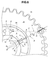
- FIG. 6 is an enlarged schematic view of substantial part of an automotive seat reclining device according to a second embodiment of the present invention.
- FIG. 7 is a graph showing a relationship between seat back load and seat back displacement in the seat reclining device according to the first embodiment of the present invention.
- FIG. 8 is a graph showing a relationship between seat back load and seat back displacement in a conventional seat reclining device.
- FIG. 9 is an enlarged schematic view of substantial part of a conventional automotive seat reclining device.
- first and second embodiments each of which refers to a seat reclining device for an automatic vehicle. It is noted that: in the first and second embodiments, like parts and portions are designated by like reference numerals to avoid repeated descriptions thereof; and the terms "front”, “rear”, “upper” and “lower” are used to describe various component parts of the seat reclining device as viewed by a vehicle passenger seated in a normal position.
- the seat reclining device of the first embodiment has a seat back angle adjustment mechanism for holding a seat back at a desired angular position with respect to a seat cushion in the automotive vehicle.
- the seat back adjustment mechanism includes a first bracket connected with a lower end of the seat back, a second bracket connected with a rear end of the seat cushion and a differential gear unit disposed between the first and second brackets to adjust the angular position of the seat back with respect to the seat cushion.
- the differential gear unit includes a first rotation member 1, a second rotation member 2, a drive bushing 3 (as a drive member), a pair of wedge plates 5 (as wedge members) and a spring 6 (as a biasing member).
- the first and second rotation members 1 and 2 are opposed to each other and coupled to the first and second brackets, respectively.
- a circular groove 1a is formed in a flat surface of the first rotation member 1 facing the second rotation member 2.
- An internal gear 1c is formed on the first rotation member 1 by forming internal gear teeth 1b in an inner circumferential wall of the circular groove 1a.
- a circular groove 2a is formed in a flat surface of the second rotation member 2 facing the first rotation member 1.
- Internal gear teeth 2d are also intermittently formed in an inner circumferential wall of the circular groove 2a.
- An external gear 2c with external gear teeth 2b are formed on the second rotation member 2.
- the external gear teeth 2b are formed in an outer circumferential surface of the external gear 2c so that the external gear 2c is fitted in the circular groove 2a and thereby integrated into the second rotation member 2 as one component part.
- the external gear 2c meshes with both of the internal gear 1c (internal gear teeth 1b) and the internal gear teeth 2d in an axial direction (thickness direction) thereof.
- the number of the internal gear teeth 1b and the number of the external gear teeth 2b are set to 34 and 33, respectively.
- the internal gear teeth 1b is one less in number than the external gear teeth 2b.
- the center O 1 of the internal gear 1c and the center O 2 of the external gear 2c differ in position from each other in a state that some part of the external gear 2c (external gear teeth 2b) is held in mesh with the corresponding part of the internal gear 1c (internal gear teeth 1b).
- the mesh part between these gears 1c and 2c is hereinafter simply referred to as "mesh H".
- a bearing sleeve 1d is formed on the first rotation member 1. Further, a bearing bore is formed in the second rotation member 2 (external gear 2c).
- the bearing sleeve 1d has an outer circumferential surface 1e coaxial with the internal gear 1c, whereas the bearing bore has an inner circumferential surface 2e coaxial with the external gear 2c.
- the inner circumferential surface 2e of the external gear 2c and the outer circumferential surface 1e of the bearing sleeve 1d are located eccentrically to define a circular eccentric space 4 between the outer circumferential surface 1e of the bearing sleeve 1d and the inner circumferential surface 2e of the external gear 2c.
- the wedge plates 5 are circumferentially movably disposed in the eccentric space 4 so as to hold the internal gear 1c and the external gear 2c in mesh with each other and prevent the occurrence of backlash in the mesh H of the internal gear 1c and the external gear 2c due to dispersion in part dimensions more effectively than a single wedge member.
- the wedge plates 5 are arranged symmetrically with base ends thereof facing each other.
- Each of the wedge plates 5 has a shape to fit with a part of an arc of the eccentric space 4 as shown in FIGS. 1 to 3 .
- Each of the wedge plates 5 also has a thickness substantially equal to the thickness of the external gear 2c and a width (radial dimension) gradually increasing toward the base end.
- Recesses 5a are formed in the base ends of the wedge plates 5, respectively.
- the spring 6 has its both ends disposed in the eccentric space 4 and engaged in the recesses 5a of the wedge plates 5, so as to bias the wedge plates 5 circumferentially away from each other in the opposite directions.
- the wedge plates 5 are inserted between the outer circumferential surface 1e of the bearing sleeve 1d and the inner circumferential surface 2e of the external gear 2c to exert a wedge effect for enlarging the eccentric space 4 and pushing the external gear 2c against the internal gear 1c so that the external gear 2c deeply meshes with the internal gear 1c with no (or little) backlash in the gear mesh H. This allows the external gear 2c and the wedge plates 5 to be held together between the internal gear 1c and the bearing sleeve 1d without play.
- the drive bushing 3 is coupled to a motor, which is fixed to the seat back, via an input shaft.
- the drive bushing 3 has a cylindrical part 3a inserted in the bearing sleeve 1d, a flange part 3b formed integral with the cylindrical part 3a so as to prevent the wedge plates 5 from falling axially out of the eccentric space 4 and a pair of push parts 3c formed on the flange part 3b so as to protrude axially from the flange part 3b into the eccentric space 4.
- the push parts 3c are located adjacent to narrow tip ends of the wedge plates 5, respectively.
- a plurality of axial spline grooves 3d are formed on an inner circumferential surface of the cylindrical part 3a so that the input shaft is engaged in the grooves 3a to transmit a rotational force of the motor to the drive bushing 3.
- connection ring 7 has a clamp portion 7a to prevent relative axial movement between the first and second rotation members 1 and 2 but allow relative rotation of the first and second rotation members 1 and 2.
- the drive bushing 3 is driven (rotated) by the motor to push either one of the push parts 3c against the tip end of the corresponding one of the wedge plates 5 toward the base end side.
- the spring 6 is then compressed slightly to push the other of the wedge plates 5 by the amount of compression of the spring 6.
- the wedge plates 5 are thus moved circumferentially in the eccentric space 4 without generating any gaps between the component parts.
- the circumferential movement of the wedge plates 5 causes a pivot of the center O 2 of the external gear 2c about the center O 1 of the internal gear 1c, thereby enabling the gear mesh H of the internal gear 1c and the external gear 2c on the side of the wedge plates 5.
- the gear mesh H is moved circumferentially together with the wedge plates 5 by the drive bushing 3.
- the second rotation member 2 rotates relative to the first rotation member 1 at a high reduction gear ratio in the direction opposite to the rotation direction of the gear mesh H (drive bushing 3) to thereby adjust the angular position of the seat back with respect to the seat cushion.
- a wedge plate 5' of a conventional seat reclining device has an inner circumferential surface formed with two circular arc sections to make line contact with the outer peripheral surface 1e of the bearing sleeve 1d in the thickness direction at one point P between these two circular arc sections as already mentioned before.
- the one-point contact of the wedge plate 5' and the bearing sleeve 1d is for the purpose of stabilizing the after-defined wedge angle ⁇ by fixing the contact point P.
- the wedge plate 5' also has an outer circumferential surface to make line contact with the inner peripheral surface 2e of the external gear 2c in the thickness direction at a point S.
- the load F 1 is the biasing force applied by the spring 6 to the wedge plate 5' along the line A of action.
- the load F 2 is applied from the bearing sleeve 1d to the wedge plate 5' via the contact point P as an external force is exerted on the seat back in a direction that tilts down the seat back under the weight of the seat back or by the passenger's seat reclining action.
- the line B of action of the load F 2 is orthogonal to the inner peripheral surface of the wedge plate 5' and passes through the center O 1 of the internal gear 1c and the contact point P between the bearing sleeve 1d and the wedge plate 5'.
- the load F 3 is applied, as a reaction force to the load F 2 , by the external gear 2c to the wedge plate 5' via the contact point S.
- the line C of action of the load F 3 is orthogonal to the outer peripheral surface of the wedge plate 5' and passes through the center O 2 of the external gear 2c, the contact point S between the external gear 2c and the wedge plate 5' and the intersection R of the lines A and B of action of the loads F 1 and F 2 .
- the loads F 1 and F 2 act on the point R radially outwardly, whereas the load F 3 acts on the point R radially inwardly and balances with the resultant of the radially outward loads F 1 and F 2 .
- the three loads F 1 , F 2 and F 3 on the wedge plate 5' balance with one another at the point R.
- the offset angle ⁇ between the line B of action of the load F 2 and the line C of action of the load F 3 is herein defined as a "wedge angle", which corresponds to the angle which a tangent to the inner circumferential surface 1e of the bearing sleeve 1d at the point P forms with a tangent to the outer circumferential surface 2e of the external gear 2c at the point S.
- the wedge angle ⁇ decreases as the position of the intersection R becomes shifted toward the wedge plate 5' (toward the left in FIG. 9 ) along the line A of action of the load F 1 and increases as the position of the intersection R becomes shifted away from the wedge plate 5' (toward the right in FIG. 9 ) along the line A of action of the load F 1 .
- the wedge plate 5' pushes the inner circumferential surface 2e of the external gear 2c under the load F 2 and moves slightly relative to the inner circumferential surface 2e of the external gear 2c toward the base end side so that the contact point S of the wedge plate 5' and the external gear 2c is displaced toward the base end side of the wedge plate 5'.
- the intersection R becomes thus shifted toward the wedge plate 5' (toward the left in FIG. 9 ) along the line A of action of the force F 1 as the contact points P and S are displaced toward the base end side of the wedge plate 5' (in the counterclockwise direction in FIG. 9 ) .
- the wedge angle ⁇ is established in such a manner that these component forces of the loads F 2 and F 3 are smaller than the frictional forces between the inner circumferential surface of the wedge plate 5' and the outer peripheral surface 1e of the bearing sleeve 1d and between the outer peripheral surface of the wedge plate 5' and the inner peripheral surface 2e of the external gear 2c.
- a component force F 3x of the load F 3 is exerted in the direction perpendicular to a line passing through the contact points P and S in the presence of the wedge angle ⁇ .
- This component force F 3x acts as a bending moment M 1 that tilts the wedge plate 5' slightly about the contact point P in the direction toward the base end side (swings the wedge plate 5' slightly within the space between the outer circumferential surface 1e of the bearing sleeve 1d and the inner circumferential surface 2e of the external gear 2c).
- the bending moment M 1 becomes large as the loads F 2 and F 3 increase with the external force on the seat back.
- the wedge plate 5' Upon receipt of such a large bending moment M 1 , the wedge plate 5' is tilted down to cause the external gear 2c to rotate the internal gear 1c together with the seat back in response to the tilting of the wedge plate 5'. Even the slight tilt of the wedge plate 5' results in large play of the upper side of the seat back.
- the conventional seat reclining device causes a displacement in the seat back by the amount of "a” or "b" soon after the application of the external force to the seat back as shown in FIG. 8 regardless of the direction of the external force on the seat back.
- the frictional resistance between the wedge plate 5' and the bearing sleeve 1d and between the wedge plate 5' and the external gear 2b increases with decrease in the wedge angle ⁇ .
- the component force F 3x of the load F 3 i.e. the bending moment M 1 decreases with the wedge angle ⁇ .
- the wedge plate 5' can be thus held firmly between the bearing sleeve 1d and the external gear 2b and prevented from being tilted without causing play in the seat back when the wedge angle ⁇ is small.
- each of the wedge plates 5 has an inner circumferential surface formed with two separate contact sections 5b and 5c to make sliding line contact with the outer circumferential surface 1e of the bearing sleeve 1d at two points P 1 and P 2 as shown in FIGS. 1 and 2 in the first embodiment.
- the circumferential surface of the wedge plate 5 is formed with reference to a circular arc of curvature radius r 0 about the center O 1 of the internal gear 1c (bearing sleeve 1d), including two relief sections 5d and 5e on circumferentially opposite sides of the wedge plate 5 and a recessed section 5g between the relief sections 5d and 5e as shown in FIG. 2 .
- the relief sections 5d and 5e are formed into circular arcs of curvature radii r 1 and r 2 , with the centers of these circular arcs differing in position from the center O 1 of the internal gear 1c (bearing sleeve 1d).
- the curvature radii r 1 and r 2 are larger than the curvature radius of the outer circumferential surface 1e of the bearing sleeve 1d so as to leave slight clearances between the relief section 5d and the outer circumferential surface 1e of the bearing sleeve 1d and between the relief section 5e and the outer circumferential surface 1e of the bearing sleeve 1d.
- the recessed section 5g is in actual a slight recess of about several hundredths of a millimeter although exaggerated in FIG. 2 for purposes of illustration.
- the contact sections 5b and 5c are defined on circumferentially opposite sides of the recessed section 5g (more specifically, between the relief section 5d and the recessed section 5g and between the relief section 5e and the recessed section 5g) so as to secure two adjacent contact points P 1 and P 2 for sliding line contact with the outer circumferential surface 1e of the bearing sleeve 1d.
- each of the wedge plates 5 has an outer circumferential surface 5f formed into a circular arc of a single curvature radius R.
- the curvature radius R is made substantially equal to and slightly smaller than the curvature radius of the inner circumferential surface 2e of the external gear 2c so that the outer circumferential surface 5f of the wedge plate 5 makes sliding line contact with the inner circumferential surface 2e of the external gear 2c at one point S.
- the wedge plate 5 is held by the bearing sleeve 1d and the external gear 2c at any position between the opposite tip and base ends.
- the operability of the wedge plate 5 depends on the position of the wedge plate 5 held by the bearing sleeve 1d and the external gear 2c and does not become stable and constant.
- the wedge plate 5 needs to be allowed to tilt toward either one of the outer circumferential surface 1e of the bearing sleeve 1d and the inner circumferential surface 2e of the external gear 2c.
- the relief sections 5d and 5e are formed on the circumferentially opposite sides of the inner circumferential surface of the wedge plate 5 so as to sandwich therebetween the contact sections 5b and 5c as mentioned above.
- the wedge plate 5 can be thus held at a fixed position, whereby both of the contact sections 5b and 5c come into contact with the outer circumferential surface 1e of the bearing sleeve 1d irrespective of the change in eccentricity of the eccentric space 4 and the position of the wedge plate 5 within the eccentric space 4.
- the load F 1 is the biasing force applied by the spring 6 to the wedge plate 5 along the line A of action.
- the load F 2 is the resultant of component forces f 1 and f 2 applied by the bearing sleeve 1d to the wedge plate 5 via the respective contact points P 1 and P 2 .
- the line B of action of the load F 2 passes through the center O 1 of the internal gear 1c and a point P between the contact points P 1 and P 2 on the inner circumferential surface of the wedge plate 5.
- the load F 3 is applied, as a reaction force to the load F 2 , by the external gear 2c to the wedge plate 5 via the contact point S.
- the line C of action of the load F 3 passes through the center O 2 of the external gear 2c, the contact point S between the external gear 2c and the wedge plate 5 and the intersection R of the lines A and B of action of the loads F 1 and F 2 .
- These three loads F 1 , F 2 and F 3 balance with one another at the intersection R of the lines A, B and C of action of the loads F 1 , F 2 and F 3 .
- the point P on the inner circumferential surface of the wedge member 5 through which the line B of action of the load F 2 passes is herein defined as a "reference point”. It means that the contact point P 1 is located on the base end side of the wedge plate 5 with respect to the reference point P, whereas the contact point P 2 is located on the tip end side of the wedge plate 5 with respect to the reference point P. As the reference point P of the wedge plate 5 is in agreement with the contact point P of the conventional wedge plate 5', the wedge angle ⁇ remains the same in the wedge plate 5 and the conventional wedge plate 5'.
- the wedge plate 5 is in particular characterized in that the contact point P 1 is located between the reference point P on the line B of action of the force F 2 and the point T on the line C of action of the force F 3 whereas the contact point P 2 is located on the tip end side of the wedge plate 5 with respect to the line C of action of the load F 3 .
- the force f 1 is exerted on the contact section 5b via the contact point P 1 in the direction that the wedge plate 5 turns slightly relative to the inner circumferential surface 2e of the external gear 2c so as to tilt the tip end side of the wedge plate 5 radially inwardly and to displace the contact point S toward the base end side of the wedge plate 5.
- the contact section 5c contacts with the outer circumferential surface 1e of the bearing sleeve 1d at the contact point P 2 so as to prevent the wedge plate 5 from being tilted and maintain the contact point S in position.
- a component force F 3x of the load F 3 in the direction perpendicular to a line passing through the contact points P 1 and S acts as a bending moment M 2
- the magnitude of the component force F 3x (bending moment M 2 ) is reduced by the amount of deviation from the point P to the point P 1 .
- the wedge plate 5 is less likely to tilt about the point P 1 even when the both of the load F 2 (the resultant of the component forces f 1 and f 2 ) and the load F 3 increase with the external load on the seat back.
- the two-point contact of the wedge plate 5 and the bearing sleeve 1d allows a reduction of the load on each contact section 5b, 5c (the pressure on the inner circumferential surface of the wedge plate 5) so as to protect the contact section 5b, 5c from wear and to ease the difficulty of moving the wedge plate 5.
- the two-point contact of the wedge plate 5 and the bearing sleeve 1d also stabilizes the attitude of the wedge plate 5 so as to move the wedge plate 5 circumferentially without swinging. The durability and operability of the wedge plate 5 can be thus improved efficiently.
- the wedge plate 5 is stably supported at three points in total, i.e., two contact points P 1 and P 2 on the inner circumferential surface and one contact point S on the outer circumferential surface 5f. It is therefore possible in the first embodiment to decrease the bending moment M 1 on the wedge plate 5, prevent the wedge plate 5 from being tilted and then reduce or eliminate play (displacement) in the seat back as shown in FIG. 7 . As there is no change of the wedge angle ⁇ between the wedge plate 5 of the first embodiment and the conventional wedge plate 5', the operability of the wedge plate 5 can be maintained without deterioration.
- the contact point P 1 is located between the lines B and C of action of the loads F 2 and F 3 in the first embodiment, the contact point P 1 may alternatively be located in such a manner that the line of action of the force f 1 on the contact point P 1 extends through the contact point S or on the slightly tip end side of the contact point S. This allows the wedge plate 5 to be easily moved by the drive bush 3 for improvement in operability.
- the seat reclining device of the second embodiment is structurally similar to that of the first embodiment, except for the location of the contact point P 1 on the contact section 5b of the wedge plate 5 as shown in FIG. 6 .
- the wedge plate 5 is supported at three points in total, i.e., two contact points P 1 and P 2 on the inner circumferential surface and one contact point S on the outer circumferential surface 5f.
- the wedge plate 5 is characterized in that the contact point P 1 is located on the base end side of the wedge plate 5 with respect to the line C of action of the load F 3 whereas the contact point P 2 is located on the tip end side of the wedge plate 5 with respect to not only the line B of action of the load F 2 but also the line C of action of the load F 3 .
- the load F 1 is the biasing force applied by the spring 6 to the wedge plate 5 along the line A of action.
- the load F 2 is the resultant of component forces f 11 and f 12 applied by the bearing sleeve 1d to the wedge plate 5 via the respective contact points P 1 and P 2 .
- the line B of action of the load F 2 passes through the reference point P.
- the load F 3 is applied by the external gear 2c to the wedge plate 5 via the contact point S.
- the line C of action of the load F 3 extends between the contact point P 1 and the reference point P.
- the load F 3 As the load F 3 is exerted in the direction between the contact points P 1 and P 2 , the load F 3 develops no component force that acts as a bending moment to tilt the wedge plate 5. It is therefore possible to prevent the wedge plate 5 from being tilted and reduce or eliminate play in the seat back in the second embodiment.
- the operability of the wedge plate can be maintained without deterioration as there is no change of the wedge angle ⁇ between the wedge plate 5 of the second embodiment and the conventional wedge plate 5'.
- the two-point contact of the wedge plate 5 and the bearing sleeve 1d allows a reduction of the load on each contact section 5b, 5c (the pressure on the inner circumferential surface of the wedge plate 5) so as to protect the contact section 5b, 5c from wear and to ease the difficulty of moving the wedge plate 5.
- the two-point contact of the wedge plate 5 and the bearing sleeve 1d also stabilizes the attitude of the wedge plate 5 so as to move the wedge plate 5 circumferentially without swinging. The durability and operability of the wedge plate 5 can be thus improved efficiently.
- first and second rotation members 1 and 2 can be connected to the seat cushion and the seat back via the brackets, respectively, although the first and second rotation members 1 and 2 are connected to the seat back and the seat cushion via the brackets in the above first and second embodiments.
- the wedge plates 5 may be modified by e.g. extending the base ends of the wedge plates 5 along the arc of the eccentric space 4 so that the wedge plates 5 are axially laminated together within the eccentric space 4.
Applications Claiming Priority (1)
| Application Number | Priority Date | Filing Date | Title |
|---|---|---|---|
| JP2008054204A JP2009207702A (ja) | 2008-03-05 | 2008-03-05 | 車両のシートリクライニング装置 |
Publications (1)
| Publication Number | Publication Date |
|---|---|
| EP2098405A2 true EP2098405A2 (de) | 2009-09-09 |
Family
ID=40674102
Family Applications (1)
| Application Number | Title | Priority Date | Filing Date |
|---|---|---|---|
| EP09000862A Withdrawn EP2098405A2 (de) | 2008-03-05 | 2009-01-22 | Fahrzeugsitzverstellvorrichtung |
Country Status (5)
| Country | Link |
|---|---|
| US (1) | US7731289B2 (de) |
| EP (1) | EP2098405A2 (de) |
| JP (1) | JP2009207702A (de) |
| KR (1) | KR20090095495A (de) |
| CN (1) | CN101524973A (de) |
Cited By (1)
| Publication number | Priority date | Publication date | Assignee | Title |
|---|---|---|---|---|
| EP2261074B1 (de) | 2009-06-09 | 2017-01-04 | Aisin Seiki Kabushiki Kaisha | Sitzneigungsvorrichtung für ein Fahrzeug |
Families Citing this family (25)
| Publication number | Priority date | Publication date | Assignee | Title |
|---|---|---|---|---|
| KR101394918B1 (ko) * | 2007-10-23 | 2014-05-14 | 카이퍼 게엠베하 운트 코. 카게 | 기어 스테이지 |
| JP5584296B2 (ja) * | 2009-08-12 | 2014-09-03 | ジョンソン コントロールズ テクノロジー カンパニー | 回転リクライナ |
| DE102009039461B4 (de) * | 2009-08-26 | 2014-10-09 | Johnson Controls Components Gmbh & Co. Kg | Beschlag für einen Fahrzeugsitz |
| DE102009041491B4 (de) * | 2009-09-10 | 2013-04-11 | Keiper Gmbh & Co. Kg | Beschlag für einen Fahrzeugsitz und Fahrzeugsitz |
| DE102010023966A1 (de) * | 2010-06-09 | 2011-12-15 | Keiper Gmbh & Co. Kg | Beschlag für einen Fahrzeugsitz |
| JP5622562B2 (ja) * | 2010-12-28 | 2014-11-12 | 富士機工株式会社 | 車両のシートリクライニング装置 |
| CN102145663B (zh) * | 2011-01-27 | 2012-09-05 | 湖北中航精机科技股份有限公司 | 座椅调角器及其自锁机构及具有该调角器的座椅 |
| JP5691793B2 (ja) * | 2011-04-22 | 2015-04-01 | アイシン精機株式会社 | シートリクライニング装置 |
| JP5692819B2 (ja) * | 2012-10-24 | 2015-04-01 | シロキ工業株式会社 | リクライニング装置 |
| KR101407256B1 (ko) * | 2012-11-28 | 2014-06-13 | 현대다이모스(주) | 차량 시트의 리클라이닝 장치 |
| US9475409B2 (en) * | 2013-06-17 | 2016-10-25 | Hubei Aviation Precision Machinery Technology Co., Ltd. | Seat recliner and oil collecting element |
| CN103273859B (zh) * | 2013-06-17 | 2015-05-06 | 湖北中航精机科技有限公司 | 一种座椅调角器以及集油元件 |
| US9205765B2 (en) * | 2013-06-27 | 2015-12-08 | Das Co., Ltd. | Recliner for vehicle seat |
| JP5913242B2 (ja) | 2013-09-13 | 2016-04-27 | シロキ工業株式会社 | リクライニング装置及びシート |
| CN104071041A (zh) * | 2014-07-03 | 2014-10-01 | 宁波金海机电厂 | 用于汽车座椅的电动调角器的差动行星齿轮传动装置 |
| JP6912699B2 (ja) * | 2016-10-25 | 2021-08-04 | 株式会社今仙電機製作所 | リクライニング装置 |
| JP6807708B2 (ja) * | 2016-10-31 | 2021-01-06 | 株式会社Tf−Metal | 車両用シートリクライニング装置 |
| JP6707295B2 (ja) * | 2016-11-17 | 2020-06-10 | シロキ工業株式会社 | リクライニング装置 |
| US10421375B2 (en) * | 2016-11-17 | 2019-09-24 | Shiroki Corporation | Reclining device |
| JP2018166556A (ja) * | 2017-03-29 | 2018-11-01 | 株式会社Tf−Metal | シートリクライニング装置 |
| JP2019090460A (ja) * | 2017-11-13 | 2019-06-13 | シロキ工業株式会社 | タウメル機構 |
| IT201800004672A1 (it) * | 2018-04-18 | 2019-10-18 | Dispositivo di reclinazione per un sedile di veicolo | |
| WO2020065515A1 (en) * | 2018-09-25 | 2020-04-02 | Martur Italy S.R.L. | Reclining device for a vehicle seat |
| US11077774B2 (en) * | 2019-08-20 | 2021-08-03 | Fisher & Company, Incorporated | High torque load power rotary recliner with anti-back drive capability and reduced backlash for car seat |
| CN112026601B (zh) * | 2020-09-15 | 2023-11-14 | 安道拓(重庆)汽车部件有限公司 | 靠背倾角调节装置 |
Citations (2)
| Publication number | Priority date | Publication date | Assignee | Title |
|---|---|---|---|---|
| JP2004033401A (ja) | 2002-07-02 | 2004-02-05 | Imasen Electric Ind Co Ltd | 自動車シートのリクライニング装置 |
| JP2008054204A (ja) | 2006-08-28 | 2008-03-06 | Mitsubishi Electric Corp | 接続装置及び端末装置及びデータ確認プログラム |
Family Cites Families (7)
| Publication number | Priority date | Publication date | Assignee | Title |
|---|---|---|---|---|
| DE4303819C2 (de) * | 1992-04-07 | 1996-08-08 | Keiper Recaro Gmbh Co | Ver- und Feststellbeschlag für Sitze, insbesondere Kraftfahrzeugsitze |
| US5634380A (en) * | 1994-03-31 | 1997-06-03 | Keiper Recaro Gmbh & Co. | Articulated fitting for seats with adjustable backrest in particular for motor vehicle seats |
| DE19938666C5 (de) | 1999-08-14 | 2008-01-03 | Keiper Gmbh & Co.Kg | Verstellbeschlag für Sitze mit neigungseinstellbarer Lehne, insbesondere für Kraftfahzeugsitze |
| DE102004007043B3 (de) * | 2004-02-12 | 2005-06-23 | Keiper Gmbh & Co. Kg | Beschlag für einen Fahrzeugsitz |
| JP4538289B2 (ja) * | 2004-09-29 | 2010-09-08 | 富士機工株式会社 | 自動車シートのリクライニング装置 |
| JP4989869B2 (ja) * | 2004-12-28 | 2012-08-01 | デルタ工業株式会社 | ブラケットの角度調整装置 |
| JP4676756B2 (ja) * | 2004-12-28 | 2011-04-27 | デルタ工業株式会社 | ブラケットの角度調整装置 |
-
2008
- 2008-03-05 JP JP2008054204A patent/JP2009207702A/ja active Pending
-
2009
- 2009-01-22 EP EP09000862A patent/EP2098405A2/de not_active Withdrawn
- 2009-02-12 US US12/370,357 patent/US7731289B2/en not_active Expired - Fee Related
- 2009-03-04 KR KR1020090018257A patent/KR20090095495A/ko not_active Application Discontinuation
- 2009-03-05 CN CN200910126183A patent/CN101524973A/zh active Pending
Patent Citations (2)
| Publication number | Priority date | Publication date | Assignee | Title |
|---|---|---|---|---|
| JP2004033401A (ja) | 2002-07-02 | 2004-02-05 | Imasen Electric Ind Co Ltd | 自動車シートのリクライニング装置 |
| JP2008054204A (ja) | 2006-08-28 | 2008-03-06 | Mitsubishi Electric Corp | 接続装置及び端末装置及びデータ確認プログラム |
Cited By (1)
| Publication number | Priority date | Publication date | Assignee | Title |
|---|---|---|---|---|
| EP2261074B1 (de) | 2009-06-09 | 2017-01-04 | Aisin Seiki Kabushiki Kaisha | Sitzneigungsvorrichtung für ein Fahrzeug |
Also Published As
| Publication number | Publication date |
|---|---|
| US20090224588A1 (en) | 2009-09-10 |
| KR20090095495A (ko) | 2009-09-09 |
| US7731289B2 (en) | 2010-06-08 |
| CN101524973A (zh) | 2009-09-09 |
| JP2009207702A (ja) | 2009-09-17 |
Similar Documents
| Publication | Publication Date | Title |
|---|---|---|
| US7731289B2 (en) | Automotive seat reclining device | |
| EP1614582B1 (de) | Neigungverstellvorrichtung | |
| US7648204B2 (en) | Recliner adjuster | |
| JP5422395B2 (ja) | 自動車部品の調整フィッティング及び調整フィッティングのラッチ固定方法 | |
| US7354109B2 (en) | Recliner adjuster having main and auxiliary lock gears | |
| KR101003718B1 (ko) | 자동차 시트용 무단 조절식 리클라이너 | |
| KR101793440B1 (ko) | 차량용 시트의 리클라이너 | |
| US10421375B2 (en) | Reclining device | |
| US20150298583A1 (en) | Recliner for vehicle seat | |
| CN112277740B (zh) | 具有偏心结构组件的转动配件 | |
| US11528992B2 (en) | Power recliner | |
| JP5262957B2 (ja) | リクライニング装置 | |
| JP7060169B2 (ja) | 逆入力遮断クラッチ | |
| KR101938576B1 (ko) | 파워 리클라이너 장치 | |
| US20070295161A1 (en) | Reclining device incorporation by reference | |
| JP5809014B2 (ja) | 減速歯車機構 | |
| WO2012001769A1 (ja) | シートバックを傾動可能に保持するシートのリクライニング装置 | |
| JP4538289B2 (ja) | 自動車シートのリクライニング装置 | |
| JP6781374B2 (ja) | リクライニング装置 | |
| EP1757482A1 (de) | Neigungswinkel-Versteller | |
| KR102442453B1 (ko) | 파워 리클라이너 | |
| JP7460893B2 (ja) | リクライニング装置 | |
| EP1757483A1 (de) | Neigungverstellvorrichtung mit Haupt- und Hilfsschlossgetrieben | |
| JP7479305B2 (ja) | リクライニング装置 | |
| JP2018068444A (ja) | リクライニング装置 |
Legal Events
| Date | Code | Title | Description |
|---|---|---|---|
| PUAI | Public reference made under article 153(3) epc to a published international application that has entered the european phase |
Free format text: ORIGINAL CODE: 0009012 |
|
| 17P | Request for examination filed |
Effective date: 20090122 |
|
| AK | Designated contracting states |
Kind code of ref document: A2 Designated state(s): AT BE BG CH CY CZ DE DK EE ES FI FR GB GR HR HU IE IS IT LI LT LU LV MC MK MT NL NO PL PT RO SE SI SK TR |
|
| AX | Request for extension of the european patent |
Extension state: AL BA RS |
|
| STAA | Information on the status of an ep patent application or granted ep patent |
Free format text: STATUS: THE APPLICATION IS DEEMED TO BE WITHDRAWN |
|
| 18D | Application deemed to be withdrawn |
Effective date: 20120801 |