EP2090938A1 - Appareil et procédé de formation d'image en utilisant un révélateur transparent - Google Patents
Appareil et procédé de formation d'image en utilisant un révélateur transparent Download PDFInfo
- Publication number
- EP2090938A1 EP2090938A1 EP09151968A EP09151968A EP2090938A1 EP 2090938 A1 EP2090938 A1 EP 2090938A1 EP 09151968 A EP09151968 A EP 09151968A EP 09151968 A EP09151968 A EP 09151968A EP 2090938 A1 EP2090938 A1 EP 2090938A1
- Authority
- EP
- European Patent Office
- Prior art keywords
- mode
- pixels
- transparent toner
- threshold value
- gloss
- Prior art date
- Legal status (The legal status is an assumption and is not a legal conclusion. Google has not performed a legal analysis and makes no representation as to the accuracy of the status listed.)
- Granted
Links
- 238000000034 method Methods 0.000 title claims description 33
- 238000012545 processing Methods 0.000 claims abstract description 196
- 238000009795 derivation Methods 0.000 claims abstract description 20
- 239000003086 colorant Substances 0.000 description 72
- 230000003247 decreasing effect Effects 0.000 description 14
- 230000006870 function Effects 0.000 description 14
- 230000010365 information processing Effects 0.000 description 13
- 238000011161 development Methods 0.000 description 11
- 208000028659 discharge Diseases 0.000 description 10
- 230000000694 effects Effects 0.000 description 10
- 230000007423 decrease Effects 0.000 description 9
- 238000004458 analytical method Methods 0.000 description 3
- 238000009877 rendering Methods 0.000 description 3
- 230000005540 biological transmission Effects 0.000 description 2
- 238000004891 communication Methods 0.000 description 2
- 238000012986 modification Methods 0.000 description 2
- 230000004048 modification Effects 0.000 description 2
- 241000237519 Bivalvia Species 0.000 description 1
- 238000004364 calculation method Methods 0.000 description 1
- 235000020639 clam Nutrition 0.000 description 1
- 238000004590 computer program Methods 0.000 description 1
- 238000007796 conventional method Methods 0.000 description 1
- 238000001816 cooling Methods 0.000 description 1
- 239000000284 extract Substances 0.000 description 1
- 230000014509 gene expression Effects 0.000 description 1
- 238000009434 installation Methods 0.000 description 1
- 239000004973 liquid crystal related substance Substances 0.000 description 1
- 239000000463 material Substances 0.000 description 1
- 230000003287 optical effect Effects 0.000 description 1
- 230000002093 peripheral effect Effects 0.000 description 1
- 238000003672 processing method Methods 0.000 description 1
- 239000002699 waste material Substances 0.000 description 1
Images


Classifications
-
- G—PHYSICS
- G03—PHOTOGRAPHY; CINEMATOGRAPHY; ANALOGOUS TECHNIQUES USING WAVES OTHER THAN OPTICAL WAVES; ELECTROGRAPHY; HOLOGRAPHY
- G03G—ELECTROGRAPHY; ELECTROPHOTOGRAPHY; MAGNETOGRAPHY
- G03G15/00—Apparatus for electrographic processes using a charge pattern
- G03G15/01—Apparatus for electrographic processes using a charge pattern for producing multicoloured copies
-
- G—PHYSICS
- G03—PHOTOGRAPHY; CINEMATOGRAPHY; ANALOGOUS TECHNIQUES USING WAVES OTHER THAN OPTICAL WAVES; ELECTROGRAPHY; HOLOGRAPHY
- G03G—ELECTROGRAPHY; ELECTROPHOTOGRAPHY; MAGNETOGRAPHY
- G03G15/00—Apparatus for electrographic processes using a charge pattern
- G03G15/50—Machine control of apparatus for electrographic processes using a charge pattern, e.g. regulating differents parts of the machine, multimode copiers, microprocessor control
- G03G15/5025—Machine control of apparatus for electrographic processes using a charge pattern, e.g. regulating differents parts of the machine, multimode copiers, microprocessor control by measuring the original characteristics, e.g. contrast, density
-
- G—PHYSICS
- G03—PHOTOGRAPHY; CINEMATOGRAPHY; ANALOGOUS TECHNIQUES USING WAVES OTHER THAN OPTICAL WAVES; ELECTROGRAPHY; HOLOGRAPHY
- G03G—ELECTROGRAPHY; ELECTROPHOTOGRAPHY; MAGNETOGRAPHY
- G03G15/00—Apparatus for electrographic processes using a charge pattern
-
- G—PHYSICS
- G03—PHOTOGRAPHY; CINEMATOGRAPHY; ANALOGOUS TECHNIQUES USING WAVES OTHER THAN OPTICAL WAVES; ELECTROGRAPHY; HOLOGRAPHY
- G03G—ELECTROGRAPHY; ELECTROPHOTOGRAPHY; MAGNETOGRAPHY
- G03G15/00—Apparatus for electrographic processes using a charge pattern
- G03G15/06—Apparatus for electrographic processes using a charge pattern for developing
- G03G15/08—Apparatus for electrographic processes using a charge pattern for developing using a solid developer, e.g. powder developer
-
- G—PHYSICS
- G03—PHOTOGRAPHY; CINEMATOGRAPHY; ANALOGOUS TECHNIQUES USING WAVES OTHER THAN OPTICAL WAVES; ELECTROGRAPHY; HOLOGRAPHY
- G03G—ELECTROGRAPHY; ELECTROPHOTOGRAPHY; MAGNETOGRAPHY
- G03G15/00—Apparatus for electrographic processes using a charge pattern
- G03G15/65—Apparatus which relate to the handling of copy material
- G03G15/6582—Special processing for irreversibly adding or changing the sheet copy material characteristics or its appearance, e.g. stamping, annotation printing, punching
- G03G15/6585—Special processing for irreversibly adding or changing the sheet copy material characteristics or its appearance, e.g. stamping, annotation printing, punching by using non-standard toners, e.g. transparent toner, gloss adding devices
-
- G—PHYSICS
- G03—PHOTOGRAPHY; CINEMATOGRAPHY; ANALOGOUS TECHNIQUES USING WAVES OTHER THAN OPTICAL WAVES; ELECTROGRAPHY; HOLOGRAPHY
- G03G—ELECTROGRAPHY; ELECTROPHOTOGRAPHY; MAGNETOGRAPHY
- G03G2215/00—Apparatus for electrophotographic processes
- G03G2215/00362—Apparatus for electrophotographic processes relating to the copy medium handling
- G03G2215/00789—Adding properties or qualities to the copy medium
- G03G2215/00805—Gloss adding or lowering device
- G03G2215/0081—Gloss level being selectable
Definitions
- the present invention relates to a method for outputting a glossy print product.
- a printing apparatus such as discussed in Japanese Patent Application Laid-Open No. 2007-183593 , which uses a transparent and glossy medium as a toner.
- the gloss of an image can be improved and an image can be coated (protected) by applying a transparent toner on the entire surface of a print product.
- an image can be output that faithfully reflects a user's desire by applying a transparent toner in a specific character and graphic shape.
- the gloss of the color toners can be increased by executing thermal fixing processing at a speed lower than a normal speed on color toners, such as cyan, magenta, yellow, and black (CMYK).
- the total amount of applied toner is generally restricted to a predetermined amount in an electrophotographic type printing apparatus that uses a toner.
- the applied toner amount ranging from 0% to 100% can be set for each latent image of each of four colors of CMYK. Therefore, the amount of applied toner up to 400% may be applied in total of the latent images.
- the toner may not be appropriately fixed and may be scattered. Therefore, in this case, an appropriate image cannot be obtained.
- a method for restricting the total amount of applied toner can be used. More specifically, a printing apparatus can restrict the total amount of applied toner to the amount equal to or smaller than a predetermined amount.
- the present invention is directed to an image forming apparatus capable of applying a gloss as appropriate as possible to an image to be printed.
- an image forming apparatus as specified in claims 1 to 6.
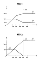
- Fig. 1 is an example graph illustrating, when the amount of each of five color toners is decreased evenly, how the amount of toners applied on a print product is restricted according to a premise of exemplary embodiments of the present invention.
- Fig. 2 is an example graph illustrating, when the amount of applied toners of five colors are decreased while maintaining an amount of the four colors of CMYK, how the amount of toners applied on a print product is restricted, according to a premise of exemplary embodiments of the present invention.
- Figs. 3A and 3B each illustrate an example of an image to be printed on which a 100% transparent toner is applied to an object thereof, for which four colors of CMYK are used, according to a premise of exemplary embodiments of the present invention.
- Fig. 4 illustrates an example of a histogram indicating the sum of density values of the four colors of CMYK for each pixel of input data according to a premise of exemplary embodiments of the present invention.
- Fig. 5 illustrates an exemplary configuration of a printing apparatus that is capable of applying a transparent toner.
- Fig. 6 illustrates an example of processing executed when the printing apparatus performs a transparent toner twice-fixing mode according to an exemplary embodiment of the present invention.
- Fig. 7 illustrates an example of a print sheet on which an image has been printed in a gloss mode according to an exemplary embodiment of the present invention.
- Fig. 8 illustrates an exemplary configuration of the printing apparatus according to a first exemplary embodiment of the present invention.
- Fig. 9 is a flow chart illustrating exemplary processing executed by the printing apparatus according to the first exemplary embodiment of the present invention.
- Fig. 10 illustrates a first example of print data (image) according to the first exemplary embodiment of the present invention.
- Fig. 11 illustrates an example of a histogram generated based on the print data illustrated in Fig. 10 according to the first exemplary embodiment of the present invention.
- Fig. 12 illustrates a second example of print data (image) according to the first exemplary embodiment of the present invention.
- Fig. 13 illustrates an example of a histogram generated based on the print data illustrated in Fig. 12 according to the first exemplary embodiment of the present invention.
- Fig. 14 illustrates a relationship of correspondence between a 0% pixel and a mode to be selected according to the first exemplary embodiment of the present invention.
- Fig. 15 illustrates an example of print data (image) according to a second exemplary embodiment of the present invention.
- Fig. 16 illustrates an example of a histogram generated based on the print data illustrated in Fig. 15 according to the second exemplary embodiment of the present invention.
- Fig. 17 is a flow chart illustrating exemplary processing executed by a printing apparatus according to the second exemplary embodiment of the present invention.
- Fig. 18 is a flow chart illustrating exemplary processing executed by a printing apparatus according to a third exemplary embodiment of the present invention.
- Fig. 19 is a flow chart illustrating exemplary processing executed by a printing apparatus according to a fourth exemplary embodiment of the present invention.
- Fig. 20 is a flow chart illustrating exemplary processing executed by a printing apparatus according to a fifth exemplary embodiment of the present invention.
- Fig. 21 illustrates an exemplary configuration of an information processing apparatus (host computer) on which a printer driver is installed according to a sixth exemplary embodiment of the present invention.
- Fig. 22 is a flow chart illustrating exemplary processing executed by the information processing apparatus (host computer) according to the sixth exemplary embodiment of the present invention.
- Fig. 23 is a flow chart illustrating exemplary processing executed by the printing apparatus according to the sixth exemplary embodiment of the present invention.
- Figs. 24A and 24B illustrate an example of print data and a transparent toner object applied to the print data, respectively, according to a seventh exemplary embodiment of the present invention.
- Fig. 25 is a flow chart illustrating exemplary processing executed by the printing apparatus according to the seventh exemplary embodiment of the present invention.
- a printing apparatus that uses a transparent toner and capable of operating in a transparent toner mode will be described.
- a transparent toner is applied at the density of 100% on the entire surface of a print product.
- various methods can be used for restricting the amount of applied toner with respect to five colors, which include four colors of CMYK and the transparent toner.
- a method for evenly decreasing the amount of each applied toner of the five colors can be used.
- Fig. 1 illustrates exemplary processing for restricting the amount of applied toner, which is performed when the amount of applied toners of the five colors is evenly decreased.
- a horizontal axis indicates input values (instructed values), represented in percentage, of the amount of applied toners (density) of four colors of CMYK.
- a vertical axis indicates values of the amount of actually applied toners, represented in percentage.
- the maximum value of the amount of applied toner of each color is 100%. Accordingly, the maximum value of the total amount of applied toners of the four colors of CMYK, for example, is 400%.
- a limit value 103 of the total amount of applied toners is 240%.
- a graph 101 indicates an example of the relationship between an input value of the amount of applied toners of the four colors of CMYK and the value of the amount of actually applied toners of the four colors of CMYK.
- a graph 102 indicates an example of the relationship between the input values of the amount of applied toners of the four colors of CMYK and the value of the amount of applied toner of the actually applied transparent toner.
- the input value of the amount of applied toner of the transparent toner is 100%.
- the transparent toner in the case where the 100% transparent toner is applied to the color toners of four colors of CMYK, if the total sum of the input values of the amount of applied toners of the four colors of CMYK exceeds 140%, the color of the image may be changed. Furthermore, the transparent toner itself decreases in the area in which the total sum of the input values of the amount of applied toners of the four colors of CMYK exceeds 140%. As a result, the amount of applied toner of the transparent toner becomes as low as 48%. Accordingly, the gloss of the transparent toner is decreased.
- a method can be used for restricting the amount of applied toners of five colors including the four colors of CMYK and the transparent toner while maintaining an appropriate amount of applied toners of the four colors of CMYK.
- Fig. 2 illustrates an example of a method for restricting the amount of applied toners, which is performed when the amount of applied toners of five colors is decreasing while maintaining an appropriate amount of applied toners of the four colors of CMYK.
- a graph 201 illustrates an example of the relationship between the input values of the amount of applied toners of the four colors of CMYK and the amount of actually applied toners of the four colors of CMYK.
- a graph 202 illustrates an example of the relationship between the input value of the amount of applied toners of the four colors of CMYK and the value of the amount of applied toner of the actually applied transparent toner.
- the amount of applied toners which is the same as the input value of the amount of applied toners of the four colors of CMYK, is applied as the amount of applied toners of the four colors of CMYK until the input value of the amount of applied toners of the four colors of CMYK reaches the limit value 103.
- the amount of applied toners of the four colors of CMYK is not restricted.
- the amount of applied toner of the actually applied transparent toner starts decreasing in the area in which the input value of the amount of applied toners of the four colors of CMYK exceeds 140% and reaches the value of 0% at the limit value 103.
- the amount of applied toner of the transparent toner becomes smaller so as to reach 0%.
- the desired gloss cannot be obtained.
- Figs. 3A and 3B each illustrates an example of an image to be printed on which a 100% transparent toner has been applied to the object in which four colors of CMYK is used.
- an object 303 is drawn on a blank sheet 301.
- a surface of the sheet 302 illustrated in Fig. 3B indicates the state of the surface of the sheet obtained by applying a 100% transparent toner 304 on the entire surface thereof including the object 303.
- the transparent toner also decreases in this case. More specifically, the amount of applied toner of the transparent toner decreases to a density of 48%. Thus, in this case, only a far less amount of gloss than the desired gloss can be obtained.
- the amount of applied toners of the five colors is decreased while maintaining the amount of applied toners of the four colors of CMYK, as illustrated in Fig. 2 , the density of the object 303 is maintained.
- the limit value 103 of the above-described total amount of applied toners is the value uniquely set for a printing apparatus. Accordingly, if the user does not recognize the limit value 103, it is extremely difficult for a user to prevent the decrease of the gloss, which occurs against the user's intention, for example, by editing original data.
- Fig. 4 illustrates example of a histogram illustrating the sum of density values (signal values such as pixel values) of the four colors of CMYK in each pixel of input data.
- the density of four colors of CMYK of each pixel of input data is a relative value indicated in percentage.
- Fig. 5 illustrates an exemplary configuration of a printing apparatus that is capable of applying a transparent toner.
- a printing apparatus 401 which is capable of applying a transparent toner, feeds a sheet from a paper feed stage 402.
- the printing apparatus 401 includes development stations 405 through 409.
- the station 405 for cyan (C), the station 406 for magenta (M), the station 407 for yellow (Y), the station 408 for black (K), and a station 409 for applying the transparent toner are installed in the printing apparatus 401.
- the toners After the toners have been developed on the surface of the sheet by the stations 405 through 409, and are fixed by a fixing device 410, the sheet is discharged on a paper discharge stage 403.
- the above-described problem that the density of the transparent toner on the object 303 decreases can be solved by performing the processing twice on one sheet in the printing apparatus 401.
- the mode for performing the processing in the above-described manner is referred to as a "transparent toner twice-fixing mode" when necessary.
- Fig. 6 illustrates an example of processing executed by the printing apparatus 401 in the case of performing the transparent toner twice-fixing mode.
- the user feeds a sheet having no image printed thereon on the paper feed stage 402.
- the printing apparatus 401 develops each of the CMYK toners by using the toners of four colors of CMYK while restricting the amount of applied toners in the above-described manner.
- the printing apparatus 401 uses the fixing device 410 to fix the toners on the surface of the sheet.
- the sheet is discharged on the paper discharge stage 403.
- processing 502 the user sets (feeds) the printed sheet, which has been discharged on the paper discharge stage 403, on the paper feed stage 402 again.
- the printing apparatus 401 applies only the transparent toner to the sheet, which is set (fed) again, by using the fixing device 410.
- the sheet is discharged on the paper discharge stage 403. Accordingly, the user can obtain a print result on which the transparent toner has been applied on the entire surface thereof in processing 503.
- the waste of both time and sheets may arise.
- the sheet that has once passed through the fixing device 410 can be curled or contracted due to the heat applied thereby. Therefore, the problem such as paper jamming can easily arise during second print processing.
- processing for cooling down the heated sheet for a predetermined wait time for example, is necessary before setting the paper printed in the processing 502 on the paper feed stage 402 again.
- a printing apparatus capable of increasing the gloss by adjusting the print processing of the color toners without using the transparent toner will be described in detail below.
- a method for adjusting the print processing a method can be used in which fixing of the color toners of CMYK is performed slowly by controlling the fixing device 410 to decrease the processing speed.
- any other method capable of increasing the gloss without using the transparent toner can be used as the example of the other methods.
- a method can be used which adjusts the speed of development by a development device. In this case, an amount of toner larger than that in the case of a normal operation can be applied. As a result, the gloss can be increased.
- the printing apparatus capable of operating in a gloss mode can be realized by removing the station 409 from the printing apparatus 401 illustrated in Fig. 5 .
- the toners of four colors of CMYK are developed on the surface of the sheet set (fed) on the paper feed stage 402 by using the stations 405 through 408, which correspond to the four colors of CMYK. As described above, the station 409 is not used in this case.
- the fixing device 410 performs the fixing processing at the speed as low as one-third of that in normal print processing of the toners of four colors of CMYK that have been developed on the sheet. By performing the above-described processing, the more amount toners can be fused than the amount of toners fused in normal print processing. Thus, the gloss of the color toners can be increased.
- Fig. 7 illustrates an example of a sheet on which an image has been printed in the gloss mode.
- an object 702 is drawn on a blank paper 701.
- the gloss mode on data to be printed
- the gloss of only the object 702 is increased.
- the printing apparatus including both the above-described transparent toner mode and the gloss mode is useful.
- the desired gloss may not be achieved due to the restriction of the amount of applied toners.
- the gloss mode it is difficult to apply gloss on the white portions and the highlight color portions of the sheet.
- the processing time and the amount of work by the user may considerably increase compared to the case of the transparent toner once-fixing mode and the gloss mode.
- an optimum gloss can be obtained by using the transparent toner twice-fixing mode.
- this mode a long processing time and a relatively large amount of work are needed. Therefore, it is natural that the user selects a mode other than the transparent toner twice-fixing mode in order to execute the processing at an appropriately high speed.
- the printing apparatus 401 described above with reference to Fig. 5 is used as a printing apparatus according to the present exemplary embodiment.
- the printing apparatus 401 includes the function for executing the gloss mode and the transparent toner once-fixing mode.
- Fig. 8 illustrates an exemplary configuration of the printing apparatus 401 according to the present exemplary embodiment.
- a central processing unit (CPU) 802 is connected to a system bus 808.
- the CPU 802 controls the following peripheral devices, which are connected to the bus 808, performs calculations therefor, and executes programs stored in a storage device.
- a network interface (I/F) 804 controls an input from an external network.
- a random access memory (RAM) 806 and a hard disk drive (HDD) 803 are the storage devices.
- a boot read-only memory (ROM) 807 stores a program for executing boot processing.
- a printer engine I/F 805 controls a communication with a printer engine 809.
- the printer engine 809 is an apparatus that develops a digital image on a surface of a physical sheet by using an electrophotographic printing method.
- the printer engine 809 includes the development stations 405 through 409 and the fixing device 410 illustrated in Fig. 4 .
- the printing apparatus 401 is primarily constituted by the above-described components.
- Fig. 9 is a flow chart illustrating exemplary processing executed by the printing apparatus 401 according to the present exemplary embodiment. Each step of exemplary embodiments is executed by the CPU 802 of the printing apparatus 401 unless otherwise described.
- step S901 the network I/F 804 receives page description language (PDL) data from an external network.
- PDL page description language
- image data is realized by the PDL data, for example.
- an exemplary acquisition unit is realized by the processing in step S901.
- step S902 the CPU 802 analyzes the PDL data input in step 901 and converts the analyzed PDL data into contone data including a multivalued signal value of each of the four colors of CMYK.
- the processing is generally referred to as "rendering".
- step S903 the CPU 802 generates a CMYK histogram based on the signal values of pixels constituting the contone data converted in step S902.
- Fig. 10 illustrates a first example of the print data (image) according to the present exemplary embodiment.
- print data 1001 is color data.
- the print data 1001 has been rendered in step S902 and has also been converted into CMYK multivalued contone data.
- print data generally used in business offices partially includes texts, graphics, and images on a blank white background area as the print data 1001 ( Fig. 10 ).
- Fig. 11 illustrates an example of a histogram generated based on the print data 1001 illustrated in Fig. 10 .
- the frequency of appearance of white pixels whose sum of the density values (signal values) of the four colors of CMYK (CMYK value) is 0%, is highest and occupies the most part of the data.
- CMYK values are discretely distributed.
- the gloss cannot be applied to the blank white area, which occupies the most part of the data, even if the user desires to apply the gloss by using the gloss mode on the data.
- the present exemplary embodiment can apply the gloss to the entire surface of the sheet by applying the transparent toner mode.
- Fig. 12 illustrates a second example of the print data (image).
- print data of a document usually used in the graphic art market is described.
- print data 1201 is color data that has been rendered in step S902 and has been converted into CMYK multivalued contone data, similar to the print data 1001 illustrated in Fig. 10 .
- a print sheet usually includes an image on its entire surface or may include texts and graphics of many various colors as in the case of a catalog of products.
- Fig. 13 illustrates an example of a histogram generated based on the print data illustrated in Fig. 12 .
- the histogram illustrated in Fig. 13 is different from that illustrated in Fig. 11 in the point that the frequency of appearance of white pixels, whose CMYK value is 0%, is lower than that illustrated in Fig. 11 . Accordingly, on the surface of an actual sheet, a most area thereof is applied with toners. Furthermore, the values of four colors of CMYK are continuously distributed.
- an exemplary generation unit is realized, for example, by executing the processing in step S903.
- step S904 the CPU 802 counts the number of 0% pixels (white pixels) according to the histogram generated in step S903.
- Fig. 14 illustrates an example of a relationship of correspondence between the 0% pixels and the selected mode according to the present exemplary embodiment.
- the gloss can be applied to the entire surface of the sheet by using the transparent toner mode as described above.
- a transparent toner mode boundary value 1404 is a predetermined value stored, for example, on the HDD 803.
- the gloss can be applied to the entire surface of the sheet by using the gloss mode, as described above.
- a gloss mode boundary value 1402 is also a predetermined value stored, for example, on the HDD 803, similar to the transparent toner mode boundary value 1404.
- an exemplary derivation unit is realized, for example, by executing the processing in step S904.
- step S905 the CPU 802 determines whether the number of 0% pixels counted in step S904 is smaller than the gloss mode boundary value 1402. If it is determined in step S905 that the number of 0% pixels counted in step S904 is smaller than the gloss mode boundary value 1402 (YES in step S905), then the processing proceeds to step S906. In step S906, the CPU 802 selects the gloss mode as the mode to be used for printing.
- step S905 determines whether the number of 0% pixels counted in step S904 is not smaller than the gloss mode boundary value 1402 (NO in step S905). If it is determined in step S905 that the number of 0% pixels counted in step S904 is not smaller than the gloss mode boundary value 1402 (NO in step S905), then the processing proceeds to step S907.
- step 907 the CPU 802 determines whether the number of 0% pixels counted in step S904 is greater than the transparent toner mode boundary value 1404. If it is determined in step S907 that the number of 0% pixels counted in step S904 is greater than the transparent toner mode boundary value 1404 (YES in step S907), then the processing proceeds to step S908. In step S908, the CPU 802 selects the transparent toner mode as the mode to be used for printing.
- step S907 if it is determined in step S907 that the number of 0% pixels counted in step S904 is equal to or smaller than the transparent toner mode boundary value 1404 (NO in step S907), then the processing proceeds to step S909.
- step S909 the CPU 802 determines which of the gloss mode and the transparent toner mode has been set as a priority mode.
- the content of the priority mode has been set by the user in advance and is stored, for example, on the HDD 803. If it is determined in step S909 that the gloss mode has been set as a priority mode (YES in step S909), then the processing proceeds to step S906.
- step S906 the CPU 802 selects the gloss mode as the mode to be used for printing.
- step S909 determines whether the transparent toner mode has been set as a priority mode (NO in step S909). If it is determined in step S909 that the transparent toner mode has been set as a priority mode (NO in step S909), then the processing proceeds to step S908. In step S908, the CPU 802 selects the transparent toner mode as the mode to be used for printing.
- a first threshold corresponds to the gloss mode boundary value 1402, for example.
- a second threshold corresponds to the transparent toner mode boundary value 1404.
- an exemplary comparison unit is realized by executing the processing in steps S905 and S907.
- an example of a selection unit in the case where the number of 0% pixels is smaller than the first threshold value is realized, for example, by executing the processing in step S906.
- an example of the selection unit in the case where the number of 0% pixels is greater than the second threshold value is realized by executing the processing in step S908, for example.
- an example of the selection unit in the case where the number of 0% pixels is equal to or greater than the first threshold value and equal to or smaller than the second threshold value is realized, for example, by executing the processing in steps S906, S908, and S909.
- step S910 the printer engine 809 performs development on the surface of the sheet with the CMYK toners without using the transparent toner.
- step S911 the printer engine 809 slowly fixes the CMYK toners, which is developed in step S906, at a speed slower than that in the case of normal fixing speed.
- the present exemplary embodiment can apply the gloss on the CMYK toners.
- step S914 the printer engine 809 discharges the sheet on which the gloss has been applied and fixed. Then, the processing executed according to the flow chart in Fig. 9 ends.
- step S908 When the transparent toner mode is selected in step S908, the processing proceeds to step S912.
- step S912 the printer engine 809 performs development on the surface of the sheet using both the CMYK toners and the transparent toner.
- the printer engine 809 can apply the gloss, in which the transparent toner is applied on the entire surface of the sheet, by fixing the developed CMYK toners and the transparent toner at the normal print speed.
- step S914 the printer engine 809 discharges the sheet on which the CMYK toners and the transparent toner are fixed. Then, the processing executed according to the flow chart in Fig. 9 ends.
- an example of a generation unit is realized, for example, by executing the processing in steps S910 through S913.
- the present exemplary embodiment in the case where the frequency of appearance of the white pixels, whose CMYK value is 0%, is equal to or smaller than the gloss mode boundary value 1402, the developed CMYK toners are slowly fixed at a speed slower than the normal speed to apply the gloss to the CMYK toners.
- the present exemplary embodiment applies the gloss on the entire surface of the sheet by using the transparent toner.
- the present exemplary embodiment using the histogram, counts the number of times of appearance of the pixels whose gloss cannot be easily reproduced. Then, the present exemplary embodiment automatically selects each mode based the result of the counting.
- the present exemplary embodiment can appropriately and automatically change the modes between the gloss mode and the transparent toner mode according to the attribute of the input print data 1001 and 1201 without requiring the user to analyze the print data.
- the present exemplary embodiment can apply the appropriate gloss to the image to be printed.
- the gloss is applied in the mode, which is set in advance by the user as the priority mode, when the frequency of appearance (the number of times of appearance) of the white pixels is greater than the gloss mode boundary value 1402 and smaller than the transparent toner mode boundary value 1404. Accordingly, the present exemplary embodiment can surely execute either one of the gloss mode and the transparent toner mode.
- the printing apparatus 401 identifies the area in which no recording material such as a toner and an ink has been applied. Thereby, the present exemplary embodiment executes the print processing by using the transparent toner mode or the gloss mode.
- the present exemplary embodiment is not limited to this. For example, it is also useful if only one threshold value is used to select the mode to be used for printing. In this case, the gloss mode is used if the frequency of appearance of the white pixels is smaller than the threshold value while the transparent toner mode is used if the frequency of appearance of the white pixels is not smaller than the threshold value.
- the print mode is automatically changed between the gloss mode and the transparent toner mode based on the frequency of appearance of the 0% pixels by focusing on the number of 0% pixels in the histogram.
- the present exemplary embodiment changes the print modes between the gloss mode and the transparent toner mode by considering the frequency of appearance of highlight color pixels whose sum of CMYK values is equal to or smaller than a threshold value.
- the present exemplary embodiment is primarily different from the above-described first exemplary embodiment in a part of the processing for changing modes between the gloss mode and the transparent toner mode. Therefore, in the following description of the present exemplary embodiment, units and components that are the same as those in the first exemplary embodiment are denoted by the same reference numerals and symbols as in Figs. 1 through 14 . Accordingly, the detailed description thereof will not be repeated here. The differences between the embodiments are addressed in detail below.
- Fig. 15 is an example of print data (image) according to the present exemplary embodiment.
- print data of an image a most part of which has been developed with highlight colors, is illustrated.
- print data 1501 includes a photograph on its entire portion.
- the color of the sky is depicted by a tint color not by a pure white.
- the tint color like this is generally called a "highlight color”.
- a most area of the print data 1501 illustrated in Fig. 15 is depicted by the highlight colors.
- Fig. 16 illustrates an example of a histogram generated based on the print data 1501 illustrated in Fig. 15 .
- the number of pixels having CMYK values ranging from 1% to several percent is greater than the number of 0% pixels indicating the color of pure white.
- the gloss mode is selected because only the number of 0% pixels is focused even when the histogram is as illustrated in Fig. 16 .
- the gloss of the area having the color of the sky in the print data 1501 is believed not to be achieved as effectively as in the present embodiment.
- Fig. 17 is a flow chart illustrating exemplary processing executed by a printing apparatus 401 according to the present exemplary embodiment.
- the CPU 802 executes the same processing as that performed in the first exemplary embodiment (see Fig. 9 ).
- step S1705 the CPU 802 counts the number of highlight pixels according to the histogram generated in step S903, differently from the first exemplary embodiment.
- the CPU 802 determines that the pixel is a highlight pixel if it is determined in step S1705 that the sum of the signal values, such as the density of four colors of CMYK (the pixel value), of a specific pixel is equal to or smaller than a predetermined boundary value (equal to or greater than 0 and equal to or smaller than a signal upper limit value).
- a predetermined boundary value equal to or greater than 0 and equal to or smaller than a signal upper limit value.
- the total sum of the density values (the signal values) of four colors of CMYK is 2%.
- the CPU 802 determines that the pixel is a highlight pixel (a highlight color) in step S1705.
- a signal upper limit value is realized by the boundary value.
- an exemplary derivation unit is realized by the processing executed in the processing in step S1705.
- step S1706 the CPU 802 determines whether the number of highlight pixels counted in step S1705 is smaller than the gloss mode boundary value 1402 stored on the HDD 803 in advance. If it is determined in step S1706 that the number of highlight pixels counted in step S1705 is smaller than the gloss mode boundary value 1402 (YES in step S1706), in which case the white and highlight color area on the sheet surface is small, the CPU 802 determines that the gloss can be obtained on the entire surface of the sheet in the gloss mode. Then, the processing proceeds to step S906. In step S906, the CPU 802 selects the gloss mode as the mode to be used for printing.
- step S1706 determines whether the number of highlight pixels counted in step S1705 is equal to or greater than the gloss mode boundary value 1402 stored in advance on the HDD 803 (NO in step S1706). If it is determined in step S1706 that the number of highlight pixels counted in step S1705 is equal to or greater than the gloss mode boundary value 1402 stored in advance on the HDD 803 (NO in step S1706), then the processing proceeds to step S1708.
- step S1708 the CPU 802 determines whether the number of highlight pixels counted in step S1705 is greater than the transparent toner mode boundary value 1404 stored in advance on the HDD 803. If it is determined in step S1708 that the number of highlight pixels counted in step S1705 is greater than the transparent toner mode boundary value 1404 (YES in step S1708), in which case a most area on the sheet surface has white and highlight colors, then the CPU 802 determines that it is necessary to apply the transparent toner mode. Then, the processing proceeds to step S908. In step S908, the CPU 802 selects the transparent toner mode as the mode to be used for printing.
- step S1708 determines whether the number of highlight pixels counted in step S1705 is equal to or smaller than the transparent toner mode boundary value 1404 (NO in step S1708). If it is determined in step S1708 that the number of highlight pixels counted in step S1705 is equal to or smaller than the transparent toner mode boundary value 1404 (NO in step S1708), then the processing proceeds to step S909.
- step S909 the CPU 802 determines which of the gloss mode and the transparent toner mode is set as the priority mode, as in the first exemplary embodiment.
- step S909 If it is determined in step S909 that the gloss mode is set as the priority mode (YES in step S909), then the processing proceeds to step S906.
- step S906 the CPU 802 selects the gloss mode.
- step S909 the transparent toner mode is set as the priority mode (NO in step S909), then the processing proceeds to step S908.
- step S908 the CPU 802 selects the transparent toner mode.
- the present exemplary embodiment can execute the printing for applying the gloss to the entire sheet surface as in the first exemplary embodiment by executing the processing based on the selected mode (steps S910 through S914).
- a first threshold value is realized, for example, by the gloss mode boundary value 1402, while a second threshold value is realized, for example, by the transparent toner mode boundary value 1404.
- an exemplary comparison unit is realized by executing the processing in steps S1706 and S1708.
- the mode can be selected between the gloss mode and the transparent toner mode by considering the frequency of appearance (the number of times of appearance) of the highlight color as well as considering the frequency of appearance of white pixels.
- the present exemplary embodiment can achieve the effect of preventing the failure of the gloss mode occurring due to the reduced amount of the applied toners, in addition to the effect described above in the above-described first exemplary embodiment.
- the number of white pixels and that of highlight pixels are counted and the result of the counting is used to select an appropriate mode. Furthermore, in the second exemplary embodiment, if the frequency of appearance (the number of times of appearance) of highlight pixels is equal to or greater than the gloss mode boundary value 1402 and is equal to or smaller than the transparent toner mode boundary value 1404, the mode is selected according to the predetermined priority mode.
- the present exemplary embodiment automatically changes modes between the gloss mode and the transparent toner mode by considering the frequency of appearance of the pixels in the area 601.
- the present exemplary embodiment is primarily different from the above-described second exemplary embodiment in only a part of the processing for changing modes between the gloss mode and the transparent toner mode.
- Fig. 18 is a flow chart illustrating exemplary processing executed by a printing apparatus 401 according to the present exemplary embodiment.
- the CPU 802 executes the same processing as that performed in the flow chart in the above-described first exemplary embodiment.
- steps S1705, S1706, and S1708 see Fig. 17
- the CPU 802 executes the same processing as that performed in the second exemplary embodiment.
- step S1705 the CPU 802 counts the number of highlight pixels.
- step S1706 the CPU 802 determines whether to select the gloss mode as the mode to be used for printing.
- step S1708 the CPU 802 determines whether to select the transparent toner mode as the mode to be used for printing. If neither of the modes is selected as the mode to be used for printing in steps S1706 and S1708, then the processing proceeds to step S1801.
- step S1801 the CPU 802 counts the number of pixels included in the area from the value, which is smaller than the limit value 103 for restricting the amount of applied toner by 100%, to the toner application amount limit value 103 (i.e., within the area 601) based on the histogram generated in step S903.
- an exemplary first derivation unit is realized, for example, by executing the processing in step S1705.
- an exemplary second derivation unit is realized, for example, by executing the processing in step S1801.
- step S1802 the CPU 802 determines whether the "number of pixels in the area 601" counted in step S1801 is equal to or greater than a predetermined value.
- the predetermined value is stored, for example, on the HDD 803.
- step S1802 If it is determined in step S1802 that the "number of pixels in the area 601" counted in step S1801 is equal to or greater than the predetermined value (YES in step S1802), in which case the CPU 802 determines that the gloss desired by the user cannot be reproduced even if the transparent toner is applied thereon, due to the restriction on the amount of applied toner, then the processing proceeds to step S906. In step S906, the CPU 802 selects the gloss mode as the mode to be used for printing.
- step S1802 determines that the "number of pixels in the area 601" counted in step S1801 is smaller than the specific predetermined value (NO in step S1802), in which case the CPU 802 determines that the desired gloss cannot be reproduced due to the restriction on the amount of applied toner only in a small area, then the processing proceeds to step S908.
- step S908 the CPU 802 selects the transparent toner mode as the mode to be used for printing.
- the printing by applying the gloss on the entire surface of the sheet can be executed by performing the processing according to the selected mode as performed in the first exemplary embodiment.
- an exemplary first comparison unit is realized, for example, by executing the processing in steps S1706 and S1708. Furthermore, an exemplary second comparison unit is realized, for example by executing the processing in step S1802. In addition, a third threshold value is realized, for example, by the predetermined value.
- an exemplary selection unit in the case where the number of highlight pixels is equal to or greater than the first threshold value and equal to or smaller than the second threshold value and the number of pixels in the area 601 is equal to or greater than the third threshold value, is realized by executing the processing in step S906.
- an exemplary selection unit in the case where the number of highlight pixels is equal to or greater than the first threshold value and equal to or smaller than the second threshold value and the number of pixels in the area 601 is not equal to or greater than the third threshold value, is realized by executing the processing in step S908.
- the mode to be used for printing is selected between the gloss mode and the transparent toner mode according to the number of pixels included in the area 601, in which the density of the color toners decreases by executing the development using the transparent toner in addition to the color toners.
- the present exemplary embodiment can prevent the failure of applying gloss desired by the user to the pixels included in the area 601 in addition to the effects achieved by the above-described first and second exemplary embodiments.
- an appropriate mode is selected between the gloss mode and the transparent toner mode according to the result of counting of the highlight pixels as described in the second exemplary embodiment.
- the present exemplary embodiment is not limited to this.
- the operation according to the present exemplary embodiment can be applied by counting the number of 0% pixels as described above in the first exemplary embodiment. More specifically, it is also useful if the processing in steps S904, S905, and S907 in Fig. 9 is executed instead of executing the processing in steps S1705, S1706, and S1708 in Fig. 18 .
- the mode used for printing is automatically changed between two modes including the "gloss mode” and the “transparent toner once-fixing mode” for fixing the four colors of CMYK toners and the transparent toner at once.
- the mode used for printing is automatically shifted among three modes including the "transparent toner twice-fixing mode", in addition to the above-described two modes, for developing and fixing the four colors of CMYK toners on the surface of the sheet before developing the transparent toner on the same surface of the sheet.
- the present exemplary embodiment is primarily different from the above-described first through third exemplary embodiments with respect to a part of the modes to be changed and a part of the processing for changing modes.
- Fig. 19 is a flow chart illustrating exemplary processing executed by a printing apparatus 401 according to the present exemplary embodiment.
- the CPU 802 executes the same processing as that executed according to the flow chart in the above-described first exemplary embodiment.
- steps S1705 and S1706 see Fig. 17
- the CPU 802 executes the same processing as that executed in the second exemplary embodiment.
- step S1705 the CPU 802 counts the number of highlight pixels.
- step S1706 the CPU 802 determines whether the number of highlight pixels counted in step S1705 is equal to or smaller than the gloss mode boundary value 1402. If it is determined in step S1706 that the number of highlight pixels counted in step S1705 is smaller than the gloss mode boundary value 1402 (YES in step S1706), in which case the area of white pixels and highlight pixels on the surface of the sheet is small, then the processing proceeds to step S906 after the CPU 802 has determined that the gloss can be applied to the entire surface of the sheet by using the gloss mode. In step S906, the CPU 802 selects the gloss mode as the mode to be used for printing. In subsequent processing in steps S910 and S911 (see Fig. 9 ), the CPU 802 executes the same processing as that executed in the first exemplary embodiment.
- step S1706 determines whether the number of highlight pixels counted in step S1705 is equal to or greater than the gloss mode boundary value 1402 (NO in step S1706). If it is determined in step S1706 that the number of highlight pixels counted in step S1705 is equal to or greater than the gloss mode boundary value 1402 (NO in step S1706), then the processing proceeds to steps S1801 and S1802. In steps S1801 and S1802, the CPU 802 executes the same processing as that executed in the third exemplary embodiment (see Fig. 18 ).
- step S1801 the CPU 802 counts the number of pixels included in the area 601. In step S1802, the CPU 802 determines whether the number of pixels in the area 601 is equal to or greater than the predetermined value.
- an exemplary first derivation unit is realized, for example, by executing the processing in step S1705.
- an exemplary second derivation unit is realized, for example, by executing the processing in step S1801.
- a first comparison unit is realized, for example, by executing the processing in step S1706.
- an exemplary second comparison unit is realized, for example, by executing the processing in step S1802.
- a fourth threshold value is realized, for example, by the gloss mode boundary value 1402, for example while a fifth threshold value is realized by the predetermined value.
- step S1802 If it is determined in step S1802 that the number of pixels in the area 601 is equal to or greater than the predetermined value (YES in step S1802), then the processing proceeds to step S1903.
- step S1903 the CPU 802 selects the transparent toner twice-fixing mode as the mode to be used for printing.
- the printer engine 809 performs the development on the sheet by using the CMYK toners.
- step S1905 the printer engine 809 fixes the developed CMYK toners at the normal print speed.
- step S1906 the printer engine 809 discharges the sheet on which the CMYK toners is fixed.
- step S1907 the printer engine 809 cools down (does not perform any processing on) the sheet discharged in step S1906 for a predetermined time in order to prevent the problem that may arise caused by twice-fixing of the transparent toner. More specifically, after completion of the processing in step S1906, the printer engine 809 can perform control for not receiving another sheet for a predetermined time or notifying the user that it is needed to wait for a predetermined time before setting (feeding) another sheet.
- step S1908 the printer engine 809 waits until the user feeds the sheet again that has been printed, discharged, and appropriately cooled down.
- step S1909 the printer engine 809 develops the transparent toner on the entire surface of the printed sheet.
- step S1920 the printer engine 809 fixes the developed transparent toner at the normal print speed.
- step S914 the printer engine 809 discharges the sheet on which the CMYK toners and the transparent toner have been fixed as in the first exemplary embodiment.
- the present exemplary embodiment can apply the gloss evenly on the entire surface of the sheet while suppressing the influence caused by the restriction of the amount of applied toner.
- step S1802 determines that the number of pixels in the area 601 is smaller than the predetermined value (NO in step S1802), in which case the CPU 802 determines that the data to be printed is data that is not so much affected by the restriction of the amount of applied toner, then the processing proceeds to step S1923.
- step S1923 the CPU 802 selects the transparent toner once-fixing mode as the mode to be used for printing.
- the CPU 802 executes the processing of steps S912 through S914 (see Fig. 9 ) of the first exemplary embodiment.
- step S912 the printer engine 809 performs the development on the surface of the sheet by using both the CMYK toners and the transparent toner.
- step S913 the printer engine 809 fixes the developed CMYK toners and the transparent toner at the normal print speed. Then, the processing proceeds to step S914.
- step S914 the printer engine 809 discharges the sheet on which the CMYK toners and the transparent toner have been fixed.
- an exemplary selection unit in the case where the number of highlight pixels is smaller than the fourth threshold value is realized, for example, by executing the processing in step S906. Furthermore, in the present exemplary embodiment, an exemplary selection unit in the case where the number of highlight pixels is equal to or greater than the fourth threshold value and the number of pixels in an area 603 is equal to or greater than the fifth threshold value is realized, for example, by executing the processing in step S1903.
- an exemplary selection unit in the case where the number of highlight pixels is equal to or greater than the fourth threshold value and the number of pixels in the area 603 is smaller than the fifth threshold value is realized by executing, for example, the processing in step S1923.
- the printing apparatus having three modes including the gloss mode, the transparent toner once-fixing mode, and the transparent toner twice-fixing mode can automatically select an appropriate mode to achieve the effect according to each of the above-described exemplary embodiments.
- an appropriate mode is selected between the gloss mode and the transparent toner mode based on the result of counting the highlight pixels as described in the second exemplary embodiment.
- the present exemplary embodiment is not limited to this.
- the operation according to the present exemplary embodiment can be achieved, for example, by counting the number of the 0% pixels as described in the first exemplary embodiment.
- the processing in steps S904 and S905 in Fig. 9 can be executed instead of the processing in steps S1705 and S1706 in Fig. 19 .
- the transparent toner twice-fixing mode can be employed instead of the transparent toner once-fixing mode as the transparent toner mode.
- the CPU 802 automatically selects either one of the three modes including the gloss mode, the transparent toner once-fixing mode, and the transparent toner twice-fixing mode based on the influence by the restricted amount of toners to be applied.
- the load on the user, when the transparent toner twice-fixing mode is used is much higher in terms of the time to be taken in completing the printing and the relatively large number of operations performed by the user.
- the transparent toner twice-fixing mode is not used according to an instruction by a user, even though a printing apparatus has the above-described three modes.
- the present exemplary embodiment is different from the fourth exemplary embodiment in a part of the processing for changing the print mode.
- Fig. 20 is a flow chart illustrating exemplary processing of the printing apparatus according to the present exemplary embodiment. Referring to Fig. 20 , in steps S901 through S903 (see Fig. 9 ), the CPU 802 executes the same processing as that in the above-described first exemplary embodiment.
- step S2001 the CPU 802 determines whether a speed priority mode has been set ON.
- the speed priority mode has been set by the user in advance and is stored on the HDD 803.
- step S2002 the CPU 802 executes a first mode selection routine.
- the first mode selection routine is a routine for executing printing by automatically selecting either one of the three modes including the gloss mode and the transparent toner mode (the transparent toner once-fixing mode) excluding the transparent toner twice-fixing mode described above in the first through third exemplary embodiments. More specifically, the CPU 802 executes, for example, either one of the processing in step S904 and subsequent processing ( Fig. 9 ), the processing in step S1705 and subsequent processing ( Fig. 17 ), and the processing in step S1705 and subsequent processing ( Fig. 18 ).
- step S2001 determines whether the speed priority mode has been set OFF (NO in step S2001). If it is determined in step S2001 that the speed priority mode has been set OFF (NO in step S2001), then the processing proceeds to step S2003.
- step S2003 the CPU 802 executes a second mode selection routine.
- the gloss is applied in priority over the print speed.
- the CPU 802 executes, for example, the printing by automatically selecting either one of the three modes including the gloss mode, the transparent toner once-fixing mode, and the transparent toner twice-fixing mode described above in the fourth exemplary embodiment. More specifically, the CPU 802 executes the processing in step S1705 and subsequent processing (see Fig. 19 ).
- the user can previously set whether the transparent toner twice-fixing mode is selected automatically as one of choices for the printing mode.
- the present exemplary embodiment can realize the effect that the user can select whether to prioritize the print speed (avoid the possible load on the user) or the gloss as well as the effects according to the first through fourth exemplary embodiments.
- the printing apparatus 401 receives normal PDL data, which does not include information about the gloss, and analyses the received PDL data by itself.
- the CPU 802 selects an appropriate mode.
- a host computer which is configured to generate PDL data, performs the analysis and notifies the appropriate mode determined based on a result of the analysis to the printing apparatus.
- the present exemplary embodiment is primarily different from the above-described first through fifth exemplary embodiments with respect to the apparatus that determines the mode to be used for printing.
- Fig. 21 illustrates an exemplary configuration of an information processing apparatus (host computer) on which the printer driver is installed in advance according to the present exemplary embodiment.
- a CPU 2100 executes a program stored on an HDD 2105.
- an application program As the programs executed by the CPU 2100, an application program, a printer driver program, an operating system (an OS), and a network printer control program can be included.
- the CPU 2100 executes control for temporarily storing information and a file necessary to execute the program on a RAM 2102 while executing the program.
- a ROM 2101 is a storage medium storing programs, such as a basic input/output (I/O) program, and various data, such as font data used in processing a document.
- the RAM 2102 is a storage medium for temporarily storing data.
- the RAM 2102 functions as a main memory or a work area of the CPU 2100.
- a flexible disk drive (FDD) 2103 is used to load programs stored on a flexible disk (FD) (storage medium) 2104 on a storage unit of the information processing apparatus 2110.
- the storage medium is not limited to an FD.
- any machine readable storage medium such as a compact disc-read only memory (CD-ROM), a CD-recordable (CD-R), a CD-rewritable (CD-RW), a personal computer (PC) card, a digital versatile disc (DVD), an integrated circuit (IC) memory card, a magneto-optical disk (MO), or a memory stick can be utilized in addition to or instead of an FD.
- CD-ROM compact disc-read only memory
- CD-R CD-recordable
- CD-RW CD-rewritable
- PC personal computer
- DVD digital versatile disc
- IC integrated circuit
- MO magneto-optical disk
- a memory stick can be utilized in addition to or instead of an FD.
- a hard disk drive (HDD) 2105 is an external storage device that functions as a large capacity memory. On the HDD 2105, application programs, a printer driver program, an OS, a network printer control program, and related programs are stored. Furthermore, a spooler is stored on the HDD 2105.
- a user interface (UI) 2106 is an interface that can be operated by the user to input an instruction. More specifically, the UI 2106 includes a keyboard and a mouse. The user instructs to input a control command to the printing apparatus on the information processing apparatus 2110 via the keyboard and the mouse of the UI 2106.
- a display 2107 displays the control command input from the UI 2106 and the state of the printing apparatus.
- the display 2107 can be realized, for example, by a liquid crystal display (LCD).
- a system bus 2108 is a data transmission path within the information processing apparatus 2110.
- a network I/F 2109 connects the information processing apparatus 2110 to a network.
- the information processing apparatus 2110 can perform data communication with an external apparatus such as a printing apparatus via the network I/F 2109.
- Fig. 22 is a flow chart illustrating exemplary processing executed by the information processing apparatus (the host computer) 2110 according to the present exemplary embodiment. Each step of the flow chart in Fig. 22 is executed by the CPU 2100 of the information processing apparatus (the host computer) 2110.
- a graphic interface waits until an object such as a text, an image, or graphics is input.
- the graphic interface is, for example, Windows GDI ® .
- the printer driver generates PDL data according to the object input in step S2201.
- image data is realized, for example, by the PDL data.
- an exemplary acquisition unit is realized, for example, by the processing executed in the processing in step S2201.
- step S2203 the printer driver analyzes the PDL data generated in step S2202 to generate the CMYK histogram illustrated in Figs. 11 , 13 , and 16 . Then, the printer driver converts the PDL data into contone data having a multivalued signal value for each of four colors of CMYK. The processing is referred to as "provisional rendering”. In step S2204, the printer driver generates the CMYK histogram based on the signal values of pixels, which constitute the contone data generated in step S2203.
- an exemplary histogram generation unit is realized, for example, by executing the processing in step S2204.
- step S2205 the printer driver counts the number of 0% pixels based on the histogram generated in step S2204.
- an exemplary derivation unit is realized by executing the processing in step S2205.
- step S2206 the printer driver determines whether the number of 0% pixels counted in step S2205 is smaller than the gloss mode boundary value 1402, which is stored in advance on the HDD 2105. If it is determined in step S2206 that the number of 0% pixels counted in step S2205 is smaller than the gloss mode boundary value 1402 (YES in step S2206), then the processing proceeds to step S2207. In step S2207, the printer driver selects the gloss mode as the mode to be used for printing.
- step S2206 determines whether the number of 0% pixels counted in step S2205 is greater than the transparent toner mode boundary value 1404 stored in advance on the HDD 2105.
- step S2208 If it is determined in step S2208 that the number of 0% pixels counted in step S2205 is greater than the transparent toner mode boundary value 1404 (YES in step S2208), then the processing proceeds to step S2209.
- step S2209 the printer driver selects the transparent toner mode as the mode to be used for printing.
- an exemplary comparison unit is realized by executing the processing in steps S2206 and S2208, for example.
- the first threshold value is realized, for example, by the gloss mode boundary value 1402.
- the second threshold value is realized, for example, by the transparent toner mode boundary value 1404.
- step S2208 determines whether the number of 0% pixels counted in step S2205 is equal to or smaller than the transparent toner mode boundary value 1404 (NO in step S2208). If it is determined in step S2208 that the number of 0% pixels counted in step S2205 is equal to or smaller than the transparent toner mode boundary value 1404 (NO in step S2208), then the processing proceeds to step S2210.
- step S2210 the printer driver determines which of the gloss mode and the transparent toner mode has been set as the priority mode.
- the priority mode has been set in advance by the user, and is stored, for example, on the HDD 2105.
- step S2210 If it is determined in step S2210 that the gloss mode has been set as the priority mode (YES in step S2210), then the processing proceeds to step S2207. In step S2207, the printer driver selects the gloss mode as the mode to be used for printing. On the other hand, if it is determined in step S2210 that the transparent toner mode has been set as the priority mode (NO in step S2210), then the processing proceeds to step S2209. In step S2209, the printer driver selects the transparent toner mode as the mode to be used for printing.
- an exemplary selection unit in the case where the number of 0% pixels is smaller than the first threshold value is realized, for example, by executing the processing in step S2206. Furthermore, an exemplary selection unit in the case where more the number of 0% pixels is greater than the second threshold value is realized, for example, by executing the processing in step S2208.
- an exemplary selection unit in the case where the number of 0% pixels is equal to or greater than the first threshold value and equal to or smaller than the second threshold value is realized, for example, by executing the processing in steps S2206, S2208, and S2210.
- step S2211 the printer driver adds job attribute information including the selected mode to the PDL data generated in step S2202.
- the job attribute information is described, for example, by the Printer Job Language (PJL).
- step S2212 the network I/F 2109 transmits the PDL data, to which the job attribute information has been added in step S2211, to the printing apparatus instructed by the user. Then, the processing according to the flow chart in Fig. 22 ends.
- an exemplary transmission unit is realized, for example, by executing the processing in step S2211.
- Fig. 23 is a flow chart illustrating exemplary processing executed by a printing apparatus according to the present exemplary embodiment.
- the hardware configuration of the printing apparatus can be realized, for example, by the exemplary configuration illustrated in Fig. 8 .
- step S2301 the network I/F 804 receives the PDL data from the information processing apparatus (the host computer) 2110 via the network.
- step S2302 the CPU 802 analyzes the PDL data input in step S2301.
- step S2303 the CPU 802 extracts job attribute information from the PDL data.
- step S2310 the CPU 802 determines which mode has been designated according to the job attribute information extracted in step S2303.
- step S2310 If it is determined in step S2310 that the gloss mode has been designated (YES in step S2310), then the processing proceeds to step S2307.
- step S2307 the CPU 802 selects the gloss mode as the mode to be used for printing. Then, in steps S910, S911, and S914, the CPU 802 executes the same processing as that in the first exemplary embodiment (see Fig. 9 ).
- step S2310 determines whether the transparent toner mode has been designated (NO in step S2310). If it is determined in step S2310 that the transparent toner mode has been designated (NO in step S2310), then the processing proceeds to step S2309. In step S2309, the CPU 802 selects the transparent toner mode as the mode to be used for printing. In steps S912 through S914, the same processing as that in the first exemplary embodiment is performed.
- the present exemplary embodiment can achieve the effect of applying the gloss by automatically selecting an appropriate mode as in the first exemplary embodiment.
- the present exemplary embodiment is described based on the first exemplary embodiment. However, the present exemplary embodiment is not limited to this.
- the present exemplary embodiment can also be applied to the second through the sixth exemplary embodiments.
- either one of the gloss mode and the transparent toner mode is selected exclusively against each other.
- the present exemplary embodiment executes the processing in the gloss mode and the processing in the transparent toner mode in parallel to each another.
- the color toners are slowly fixed by decreasing the fixing speed while the transparent toner is applied at the same time.
- both effects can be obtained.
- the present exemplary embodiment is primarily different from the above-described first through sixth exemplary embodiments with respect to a part of the processing for applying the mode.
- Figs. 24A and 24B illustrate an example of print data and a transparent toner object, which is applied to the print data, respectively, according to the present exemplary embodiment.
- print data 2301 includes a text, graphics, and a photograph. Most area of the print data 2301 is a blank white area.
- the present exemplary embodiment applies the transparent toner on a transparent toner object 2302 (see Fig. 24B ) and uses the gloss mode at the same time to evenly apply the gloss to the entire surface of the sheet.
- Fig. 25 is a flow chart illustrating exemplary processing executed by the printing apparatus according to the present exemplary embodiment.
- the network I/F 804 receives the PDL data from an external network.
- the CPU 802 renders the PDL data input in step 2501.
- step S2503 the CPU 802 generates a CMYK histogram based on a result of the rendering in step S2502.
- the 0% pixels are interested in the histogram.
- step S2504 the CPU 802 determines an object to be a background white object, which, of the 0% pixels, does not belong to any object.
- the CPU 802 generates a transparent toner object 2302 including 0% pixels based on the background white object.
- step S2505 the printer engine 809 performs the development of the four colors of CMYK on the surface of the sheet. Furthermore, the printer engine 809 uses the transparent toner to develop the transparent toner object 2302 on the same surface of the sheet as the sheet on which the four colors of CMYK have been developed.
- step S2506 the printer engine 809 fixes five colors of toners developed in step S2505 at the speed slower than the normal print speed.
- step S2507 the printer engine 809 discharges the sheet on which the five colors of toners have been fixed.
- the present exemplary embodiment generates the transparent toner object 2302 having 0% pixels based on the object that does not belong to any object, among the 0% pixels. Furthermore, the transparent toner object 2302 is developed on the surface of the sheet by using the transparent toner using the transparent toner mode. While executing the development processing, the present exemplary embodiment develops the four colors of CMYK corresponding to the other objects on the surface of the same sheet as the surface of the sheet on which the transparent toner object 2302 has been developed.
- the gloss mode is applied on the surface of the sheet on which the five colors of toners have been developed. Furthermore, the developed five colors of toners are fixed at a speed slower than the normal speed. Thus, the gloss can be applied to both the transparent toner and the color toners.
- the printing apparatus executes the above-described processing.
- the present exemplary embodiment is not limited to this.
- a similar effect can be realized if the printer driver executes the processing described in the present exemplary embodiment.
- the printer driver executes the processing in steps S2501 through S2504 in Fig. 25 to transmit the transparent toner object 2302 and the PDL data to the printing apparatus while the printing apparatus executes the processing in steps S2505 through S2507 based on the received transparent toner object 2302 and PDL data.
- the highlight pixel described in the second exemplary embodiment can be applied in the processing of the present exemplary embodiment instead of the 0% pixels.
- Each unit and component constituting the image forming apparatus and the information processing apparatus and each step constituting the image forming method and the information processing method according to each of the above-described exemplary embodiments of the present invention can also be realized by executing a program stored on a RAM or a ROM of a computer with a CPU of the computer.
- the program and a computer-readable recording medium recording the program are included in the scope of the present invention.
- the present invention can be realized, for example, in a system, an apparatus, a method, a program, or a storage medium storing the program. More specifically, the present invention can be applied to a system including a plurality of devices and to an apparatus that includes one device.
- the present invention can be realized by directly or remotely supplying a program of software realizing functions of the above-described exemplary embodiments (in the exemplary embodiments, the program corresponding to the processing performed according to the flow charts in Fig. 9 , Figs. 17 through 20 , Figs. 22 and 23 , and Fig. 25 ) to a system or an apparatus.
- the present invention can also be realized by reading and executing the supplied program code by the system or a computer of the apparatus.
- the program code itself which is installed on the computer for performing the functional processing of the present invention by the computer, realizes the present invention. That is, the present invention also includes the computer program realizing the functional processing of the present invention.
- the program can be configured in any form, such as object code, a program executed by an interpreter, and script data supplied to an OS.
- a floppy disk a hard disk, an optical disk, an MO, a CD-ROM, a CD-R, a CD-RW, a magnetic tape, a nonvolatile memory card, a ROM, and a DVD (a DVD-read only memory (DVD-ROM) and a DVD-recordable (DVD-R)), for example, can be used.
- a floppy disk a hard disk, an optical disk, an MO, a CD-ROM, a CD-R, a CD-RW, a magnetic tape, a nonvolatile memory card, a ROM, and a DVD (a DVD-read only memory (DVD-ROM) and a DVD-recordable (DVD-R)), for example, can be used.
- DVD-ROM DVD-read only memory
- DVD-R DVD-recordable
- the above program can also be supplied by connecting to a web site on the Internet by using a browser of a client computer and by downloading the program from the web site to a recording medium such as a hard disk.
- the above program can also be supplied by downloading a compressed file that includes an automatic installation function from the web site to a recording medium such as a hard disk.
- the functions of the above embodiments can also be realized by dividing the program code into a plurality of files and downloading each divided file from different web sites. That is, a World Wide Web (WWW) server for allowing a plurality of users to download the program file for realizing the functional processing configures the present invention.
- WWW World Wide Web
- the encrypted program can also be supplied by distributing a storage medium such as a CD-ROM and the like, which stores the program according to the present invention, by allowing the user who is qualified for a predetermined condition to download key information for decoding the encryption from the web site via the Internet, and by executing the encrypted program code to install it on the computer by using the key information.
- a storage medium such as a CD-ROM and the like, which stores the program according to the present invention
- the functions according to the embodiments described above can be realized by executing the program code read by the computer.
- the functions are realized by the processing in which an OS or the like carries out a part of or the whole of the actual processing based on an instruction given by the program code.
- the program code read out of a storage medium can be written into a memory of a function expansion board equipped in a computer or into a memory of a function expansion unit connected to the computer.
- a CPU provided on the function expansion board or the function expansion unit can execute part or all of the processing to realize the functions of the above-described exemplary embodiments.
- each of the embodiments of the present invention can output a print product having an appropriate gloss.
- An image forming apparatus includes acquisition means configured to acquire image data, generation means configured to generate a histogram based on a signal value of each pixel in the image data acquired by the acquisition means, derivation means configured to derive the number of pixels matching a first condition in the histogram generated by the generation means, and selection means configured to select, according to the number of pixels derived by the derivation means, one of a fixing processing adjustment mode for increasing a degree of gloss of a print product by adjusting fixing processing and a transparent toner mode for increasing a degree of gloss of a print product by using a transparent toner.
Landscapes
- Physics & Mathematics (AREA)
- General Physics & Mathematics (AREA)
- Engineering & Computer Science (AREA)
- Microelectronics & Electronic Packaging (AREA)
- Color Electrophotography (AREA)
- Control Or Security For Electrophotography (AREA)
- Image Processing (AREA)
- Facsimile Image Signal Circuits (AREA)
- Color Image Communication Systems (AREA)
- Color, Gradation (AREA)
Applications Claiming Priority (1)
| Application Number | Priority Date | Filing Date | Title |
|---|---|---|---|
| JP2008035097A JP5197056B2 (ja) | 2008-02-15 | 2008-02-15 | 画像形成装置、画像形成方法、及びコンピュータプログラム |
Publications (2)
| Publication Number | Publication Date |
|---|---|
| EP2090938A1 true EP2090938A1 (fr) | 2009-08-19 |
| EP2090938B1 EP2090938B1 (fr) | 2018-04-11 |
Family
ID=40599673
Family Applications (1)
| Application Number | Title | Priority Date | Filing Date |
|---|---|---|---|
| EP09151968.6A Expired - Fee Related EP2090938B1 (fr) | 2008-02-15 | 2009-02-03 | Appareil et procédé de formation d'image en utilisant un révélateur transparent |
Country Status (5)
| Country | Link |
|---|---|
| US (2) | US8335012B2 (fr) |
| EP (1) | EP2090938B1 (fr) |
| JP (1) | JP5197056B2 (fr) |
| KR (1) | KR101032481B1 (fr) |
| CN (1) | CN101510061B (fr) |
Cited By (3)
| Publication number | Priority date | Publication date | Assignee | Title |
|---|---|---|---|---|
| EP2221673A1 (fr) * | 2009-01-30 | 2010-08-25 | Canon Kabushiki Kaisha | Appareil de traitement d'images, programme, support d'enregistrement et système de formation d'images |
| EP2221672A1 (fr) * | 2009-01-30 | 2010-08-25 | Canon Kabushiki Kaisha | Dispositif de commande pour ajuster de la brillance d'une partie sélectionnée d'une feuille imprimée en utilisant un révélateur transparent |
| EP2299688A3 (fr) * | 2009-09-16 | 2013-10-23 | Fuji Xerox Co., Ltd. | Appareil de traitement d'images et procédé de traitement d'images |
Families Citing this family (26)
| Publication number | Priority date | Publication date | Assignee | Title |
|---|---|---|---|---|
| US20090169277A1 (en) * | 2007-12-27 | 2009-07-02 | Fowlkes William Y | On-demand print finishing system using surface detection and replication |
| JP2010271546A (ja) * | 2009-05-21 | 2010-12-02 | Canon Inc | 画像形成装置及びその制御方法、及びプログラム |
| JP5473492B2 (ja) * | 2009-08-31 | 2014-04-16 | キヤノン株式会社 | 画像形成装置、画像形成装置の制御方法、及びプログラム |
| JP5421755B2 (ja) * | 2009-12-10 | 2014-02-19 | キヤノン株式会社 | 画像形成装置、画像形成装置の制御方法、及びプログラム |
| JP5451418B2 (ja) * | 2010-01-22 | 2014-03-26 | キヤノン株式会社 | 画像形成装置 |
| JP5606150B2 (ja) * | 2010-05-17 | 2014-10-15 | キヤノン株式会社 | 画像処理装置及び画像処理方法 |
| JP5676973B2 (ja) | 2010-08-23 | 2015-02-25 | キヤノン株式会社 | 画像形成装置 |
| JP5631118B2 (ja) | 2010-08-26 | 2014-11-26 | キヤノン株式会社 | 画像形成システム |
| JP5794062B2 (ja) * | 2010-09-15 | 2015-10-14 | 株式会社リコー | 情報処理装置、データ生成方法及びプログラム |
| JP5794088B2 (ja) * | 2010-10-28 | 2015-10-14 | 株式会社リコー | プリンタコントローラ、画像形成装置、網点信号生成方法 |
| JP2012185380A (ja) * | 2011-03-07 | 2012-09-27 | Fuji Xerox Co Ltd | 画像処理装置、画像形成装置、及びプログラム |
| JP5910185B2 (ja) * | 2011-03-18 | 2016-04-27 | 株式会社リコー | 印刷制御装置、印刷制御システム、印刷制御方法、及びプログラム |
| JP5845986B2 (ja) * | 2011-03-18 | 2016-01-20 | 株式会社リコー | 印刷制御装置、印刷システム、印刷制御方法およびプログラム |
| JP2012226549A (ja) * | 2011-04-19 | 2012-11-15 | Canon Inc | 印刷制御装置及び印刷制御方法 |
| JP6056255B2 (ja) * | 2011-09-16 | 2017-01-11 | 株式会社リコー | 制御装置、画像形成システムおよびプログラム |
| JP2013235567A (ja) | 2012-04-11 | 2013-11-21 | Ricoh Co Ltd | 印刷制御装置、印刷制御システム、印刷制御方法及び印刷制御プログラム |
| JP2013230586A (ja) * | 2012-04-27 | 2013-11-14 | Seiko Epson Corp | 印刷データ生成装置、印刷方法およびプログラム |
| JP5934123B2 (ja) * | 2013-01-23 | 2016-06-15 | 株式会社沖データ | 画像形成装置 |
| US8934144B2 (en) | 2013-02-28 | 2015-01-13 | Ricoh Co. Ltd | Overcoat processing mechanism |
| JP5918176B2 (ja) * | 2013-07-26 | 2016-05-18 | 京セラドキュメントソリューションズ株式会社 | 画像形成装置 |
| JP6217339B2 (ja) * | 2013-11-20 | 2017-10-25 | 株式会社リコー | 印刷制御装置、印刷制御方法及びプログラム |
| JP2015135477A (ja) * | 2013-12-20 | 2015-07-27 | 株式会社リコー | 画像処理装置、画像形成システム、画像処理方法およびプログラム |
| WO2016116141A1 (fr) | 2015-01-20 | 2016-07-28 | Hewlett-Packard Indigo B.V. | Impression électrophotographique et pelliculage |
| WO2016116142A1 (fr) | 2015-01-20 | 2016-07-28 | Hewlett-Packard Indigo B.V. | Composition d'encre électrophotographique liquide |
| CN107077088B (zh) | 2015-01-20 | 2020-04-10 | 惠普印迪戈股份公司 | 电子照相印刷和上光 |
| US10448179B2 (en) * | 2017-06-12 | 2019-10-15 | Genelec Oy | Personal sound character profiler |
Citations (4)
| Publication number | Priority date | Publication date | Assignee | Title |
|---|---|---|---|---|
| EP0864942A1 (fr) * | 1997-03-14 | 1998-09-16 | Agfa-Gevaert N.V. | Méthode de commande de la brillance dans un appareil électrographique |
| JP2004271910A (ja) * | 2003-03-07 | 2004-09-30 | Ricoh Co Ltd | 画像形成装置 |
| US20060133870A1 (en) * | 2004-12-22 | 2006-06-22 | Ng Yee S | Method and apparatus for printing using a tandem electrostatographic printer |
| JP2007183593A (ja) | 2005-12-06 | 2007-07-19 | Canon Inc | 画像形成装置 |
Family Cites Families (20)
| Publication number | Priority date | Publication date | Assignee | Title |
|---|---|---|---|---|
| JP3526149B2 (ja) * | 1996-10-21 | 2004-05-10 | 富士ゼロックス株式会社 | カラー画像形成方法及びカラー画像形成装置 |
| JP2002341619A (ja) * | 2001-05-11 | 2002-11-29 | Fuji Xerox Co Ltd | 光沢付与装置及びこれを用いたカラー画像形成装置 |
| JP3945281B2 (ja) * | 2002-03-19 | 2007-07-18 | 富士ゼロックス株式会社 | 画像形成装置 |
| US6687483B2 (en) * | 2002-05-30 | 2004-02-03 | Nexpress Solutions Llc | Fuser apparatus for adjusting gloss of a fused toner image and method for fusing a toner image to a receiver |
| JP2005119279A (ja) * | 2003-09-24 | 2005-05-12 | Seiko Epson Corp | 印刷装置、印刷制御装置、印刷制御方法および印刷装置制御プログラム |
| US7139521B2 (en) * | 2003-12-23 | 2006-11-21 | Eastman Kodak Company | Gloss and differential gloss control methodology |
| JP2005196061A (ja) * | 2004-01-09 | 2005-07-21 | Fuji Xerox Co Ltd | 画像形成方法 |
| US7113718B2 (en) * | 2004-04-30 | 2006-09-26 | Eastman Kodak Company | Method and apparatus for reducing image artifacts caused by release fluid in an electrophotographic machine |
| JP2005338161A (ja) * | 2004-05-24 | 2005-12-08 | Canon Inc | 画像形成装置 |
| US7236734B2 (en) * | 2005-02-22 | 2007-06-26 | Eastman Kodak Company | Method and apparatus for electrostatographic printing with enhanced color gamut |
| JP4423220B2 (ja) * | 2005-03-02 | 2010-03-03 | キヤノン株式会社 | 画像形成装置 |
| JP2006251062A (ja) * | 2005-03-08 | 2006-09-21 | Canon Inc | 画像形成装置 |
| JP2007086747A (ja) * | 2005-08-22 | 2007-04-05 | Canon Inc | 画像形成装置 |
| JP4250623B2 (ja) * | 2005-08-31 | 2009-04-08 | キヤノン株式会社 | 画像形成装置及び光沢度制御方法 |
| JP2007065459A (ja) * | 2005-09-01 | 2007-03-15 | Fujifilm Corp | 画像形成システムおよび記録媒体 |
| US8086124B2 (en) | 2005-12-06 | 2011-12-27 | Canon Kabushiki Kaisha | Image forming apparatus |
| JP4882390B2 (ja) * | 2006-01-25 | 2012-02-22 | 富士ゼロックス株式会社 | 画像処理装置 |
| US7656556B2 (en) * | 2007-02-28 | 2010-02-02 | Xerox Corporation | Detection of a differential gloss region in a cluster-screen halftone image using filters each having a different polarization |
| JP5293454B2 (ja) * | 2009-06-26 | 2013-09-18 | 富士ゼロックス株式会社 | 画像形成装置及び画像形成プログラム |
| US8275300B2 (en) * | 2010-03-30 | 2012-09-25 | Eastman Kodak Company | Forming surface finish by electrophotographic toner fusing |
-
2008
- 2008-02-15 JP JP2008035097A patent/JP5197056B2/ja not_active Expired - Fee Related
-
2009
- 2009-02-03 EP EP09151968.6A patent/EP2090938B1/fr not_active Expired - Fee Related
- 2009-02-13 US US12/371,457 patent/US8335012B2/en not_active Expired - Fee Related
- 2009-02-13 KR KR1020090011967A patent/KR101032481B1/ko active IP Right Grant
- 2009-02-16 CN CN2009100056684A patent/CN101510061B/zh not_active Expired - Fee Related
-
2012
- 2012-09-14 US US13/617,654 patent/US8493620B2/en not_active Expired - Fee Related
Patent Citations (4)
| Publication number | Priority date | Publication date | Assignee | Title |
|---|---|---|---|---|
| EP0864942A1 (fr) * | 1997-03-14 | 1998-09-16 | Agfa-Gevaert N.V. | Méthode de commande de la brillance dans un appareil électrographique |
| JP2004271910A (ja) * | 2003-03-07 | 2004-09-30 | Ricoh Co Ltd | 画像形成装置 |
| US20060133870A1 (en) * | 2004-12-22 | 2006-06-22 | Ng Yee S | Method and apparatus for printing using a tandem electrostatographic printer |
| JP2007183593A (ja) | 2005-12-06 | 2007-07-19 | Canon Inc | 画像形成装置 |
Cited By (5)
| Publication number | Priority date | Publication date | Assignee | Title |
|---|---|---|---|---|
| EP2221673A1 (fr) * | 2009-01-30 | 2010-08-25 | Canon Kabushiki Kaisha | Appareil de traitement d'images, programme, support d'enregistrement et système de formation d'images |
| EP2221672A1 (fr) * | 2009-01-30 | 2010-08-25 | Canon Kabushiki Kaisha | Dispositif de commande pour ajuster de la brillance d'une partie sélectionnée d'une feuille imprimée en utilisant un révélateur transparent |
| US8351809B2 (en) | 2009-01-30 | 2013-01-08 | Canon Kabushiki Kaisha | Control apparatus, program, recording medium, and image forming system |
| US8736900B2 (en) | 2009-01-30 | 2014-05-27 | Canon Kabushiki Kaisha | Information processing apparatus, image forming system, method, and medium for forming transparent toner image to increase glossiness based on recording medium properties |
| EP2299688A3 (fr) * | 2009-09-16 | 2013-10-23 | Fuji Xerox Co., Ltd. | Appareil de traitement d'images et procédé de traitement d'images |
Also Published As
| Publication number | Publication date |
|---|---|
| KR101032481B1 (ko) | 2011-05-03 |
| US8335012B2 (en) | 2012-12-18 |
| CN101510061B (zh) | 2011-07-13 |
| EP2090938B1 (fr) | 2018-04-11 |
| US20130016378A1 (en) | 2013-01-17 |
| JP2009190336A (ja) | 2009-08-27 |
| KR20090088821A (ko) | 2009-08-20 |
| US8493620B2 (en) | 2013-07-23 |
| JP5197056B2 (ja) | 2013-05-15 |
| US20090207429A1 (en) | 2009-08-20 |
| CN101510061A (zh) | 2009-08-19 |
Similar Documents
| Publication | Publication Date | Title |
|---|---|---|
| EP2090938B1 (fr) | Appareil et procédé de formation d'image en utilisant un révélateur transparent | |
| CN1260070C (zh) | 打印控制装置及其显示方法 | |
| EP2221672A1 (fr) | Dispositif de commande pour ajuster de la brillance d'une partie sélectionnée d'une feuille imprimée en utilisant un révélateur transparent | |
| CN1606329A (zh) | 信息处理装置和信息处理方法 | |
| US20080297830A1 (en) | Printer with outsourcing capability for color copies | |
| JP2007272903A (ja) | カラーおよび白黒混在ドキュメントを印刷するためのプリントショップ管理方法および装置 | |
| US7636176B2 (en) | Image forming apparatus, method and storage medium | |
| US7933526B2 (en) | Image forming apparatus and image forming method with forms for printing according to consumable material | |
| US8472830B2 (en) | Serial duplex image forming system for duplex printing and display of assignment of logical pages | |
| US9684273B2 (en) | Apparatus that forms an image on a medium using a plurality of erasable materials and erasing apparatus | |
| EP2919451A2 (fr) | Appareil, procédé de traitement d'image et programme | |
| CN101794200B (zh) | 数据转换装置、打印装置以及数据转换方法 | |
| US20080174801A1 (en) | Image Forming Data Preprocessing System, Image Forming Apparatus and Computer | |
| US8711425B2 (en) | Selecting one of a plurality of print modes based on pixel coverage of a document | |
| US20190025745A1 (en) | Print control apparatus, printer, display apparatus, and print system | |
| JP5739295B2 (ja) | 画像形成装置及びプリンタドライバプログラム | |
| JP6083323B2 (ja) | 画像形成方法、画像形成装置、画像形成プログラム、および記録媒体 | |
| US9239971B2 (en) | Image processing apparatus, method, and program product determining show-through of image formed on translucent print medium | |
| JP2016224229A (ja) | 画像形成装置、画像形成方法、およびプログラム | |
| US20110036256A1 (en) | Print setup device, print setup method, and computer readable recording medium storing print setup proram | |
| JP2008005064A (ja) | 画像生成システム、画像データ生成装置、印刷装置および画像データ生成プログラム | |
| JP2012150361A (ja) | 印刷システム、制御方法、およびプログラム | |
| JP2006093898A (ja) | 画像形成方法及び画像形成装置 | |
| JP6299278B2 (ja) | 画像形成装置、印刷方法、およびコンピュータプログラム | |
| JP2004157610A (ja) | 情報処理装置 |
Legal Events
| Date | Code | Title | Description |
|---|---|---|---|
| PUAI | Public reference made under article 153(3) epc to a published international application that has entered the european phase |
Free format text: ORIGINAL CODE: 0009012 |
|
| AK | Designated contracting states |
Kind code of ref document: A1 Designated state(s): AT BE BG CH CY CZ DE DK EE ES FI FR GB GR HR HU IE IS IT LI LT LU LV MC MK MT NL NO PL PT RO SE SI SK TR |
|
| AX | Request for extension of the european patent |
Extension state: AL BA RS |
|
| 17P | Request for examination filed |
Effective date: 20100219 |
|
| AKX | Designation fees paid |
Designated state(s): DE ES FR GB IT NL |
|
| 17Q | First examination report despatched |
Effective date: 20151216 |
|
| GRAP | Despatch of communication of intention to grant a patent |
Free format text: ORIGINAL CODE: EPIDOSNIGR1 |
|
| INTG | Intention to grant announced |
Effective date: 20171027 |
|
| GRAS | Grant fee paid |
Free format text: ORIGINAL CODE: EPIDOSNIGR3 |
|
| GRAA | (expected) grant |
Free format text: ORIGINAL CODE: 0009210 |
|
| AK | Designated contracting states |
Kind code of ref document: B1 Designated state(s): DE ES FR GB IT NL |
|
| REG | Reference to a national code |
Ref country code: GB Ref legal event code: FG4D |
|
| REG | Reference to a national code |
Ref country code: DE Ref legal event code: R096 Ref document number: 602009051684 Country of ref document: DE |
|
| REG | Reference to a national code |
Ref country code: NL Ref legal event code: MP Effective date: 20180411 |
|
| PG25 | Lapsed in a contracting state [announced via postgrant information from national office to epo] |
Ref country code: NL Free format text: LAPSE BECAUSE OF FAILURE TO SUBMIT A TRANSLATION OF THE DESCRIPTION OR TO PAY THE FEE WITHIN THE PRESCRIBED TIME-LIMIT Effective date: 20180411 |
|
| PG25 | Lapsed in a contracting state [announced via postgrant information from national office to epo] |
Ref country code: ES Free format text: LAPSE BECAUSE OF FAILURE TO SUBMIT A TRANSLATION OF THE DESCRIPTION OR TO PAY THE FEE WITHIN THE PRESCRIBED TIME-LIMIT Effective date: 20180411 |
|
| REG | Reference to a national code |
Ref country code: DE Ref legal event code: R097 Ref document number: 602009051684 Country of ref document: DE |
|
| PLBE | No opposition filed within time limit |
Free format text: ORIGINAL CODE: 0009261 |
|
| STAA | Information on the status of an ep patent application or granted ep patent |
Free format text: STATUS: NO OPPOSITION FILED WITHIN TIME LIMIT |
|
| PG25 | Lapsed in a contracting state [announced via postgrant information from national office to epo] |
Ref country code: IT Free format text: LAPSE BECAUSE OF FAILURE TO SUBMIT A TRANSLATION OF THE DESCRIPTION OR TO PAY THE FEE WITHIN THE PRESCRIBED TIME-LIMIT Effective date: 20180411 |
|
| 26N | No opposition filed |
Effective date: 20190114 |
|
| PGFP | Annual fee paid to national office [announced via postgrant information from national office to epo] |
Ref country code: DE Payment date: 20190426 Year of fee payment: 11 |
|
| GBPC | Gb: european patent ceased through non-payment of renewal fee |
Effective date: 20190203 |
|
| PG25 | Lapsed in a contracting state [announced via postgrant information from national office to epo] |
Ref country code: GB Free format text: LAPSE BECAUSE OF NON-PAYMENT OF DUE FEES Effective date: 20190203 |
|
| PG25 | Lapsed in a contracting state [announced via postgrant information from national office to epo] |
Ref country code: FR Free format text: LAPSE BECAUSE OF NON-PAYMENT OF DUE FEES Effective date: 20190228 |
|
| REG | Reference to a national code |
Ref country code: DE Ref legal event code: R119 Ref document number: 602009051684 Country of ref document: DE |
|
| PG25 | Lapsed in a contracting state [announced via postgrant information from national office to epo] |
Ref country code: DE Free format text: LAPSE BECAUSE OF NON-PAYMENT OF DUE FEES Effective date: 20200901 |