EP2088965B1 - Platzierung eines segmentierten Rings - Google Patents
Platzierung eines segmentierten Rings Download PDFInfo
- Publication number
- EP2088965B1 EP2088965B1 EP07849540A EP07849540A EP2088965B1 EP 2088965 B1 EP2088965 B1 EP 2088965B1 EP 07849540 A EP07849540 A EP 07849540A EP 07849540 A EP07849540 A EP 07849540A EP 2088965 B1 EP2088965 B1 EP 2088965B1
- Authority
- EP
- European Patent Office
- Prior art keywords
- segments
- annulus
- patient
- segment
- annuloplasty
- Prior art date
- Legal status (The legal status is an assumption and is not a legal conclusion. Google has not performed a legal analysis and makes no representation as to the accuracy of the status listed.)
- Not-in-force
Links
- 238000004873 anchoring Methods 0.000 claims description 94
- 230000004044 response Effects 0.000 claims description 20
- 210000002837 heart atrium Anatomy 0.000 claims description 5
- 238000005452 bending Methods 0.000 claims description 2
- 210000005246 left atrium Anatomy 0.000 description 36
- 210000004115 mitral valve Anatomy 0.000 description 23
- 238000000034 method Methods 0.000 description 22
- 210000001519 tissue Anatomy 0.000 description 17
- 239000007943 implant Substances 0.000 description 13
- 210000005245 right atrium Anatomy 0.000 description 9
- 210000003709 heart valve Anatomy 0.000 description 8
- 229910001000 nickel titanium Inorganic materials 0.000 description 7
- HLXZNVUGXRDIFK-UHFFFAOYSA-N nickel titanium Chemical compound [Ti].[Ti].[Ti].[Ti].[Ti].[Ti].[Ti].[Ti].[Ti].[Ti].[Ti].[Ni].[Ni].[Ni].[Ni].[Ni].[Ni].[Ni].[Ni].[Ni].[Ni].[Ni].[Ni].[Ni].[Ni] HLXZNVUGXRDIFK-UHFFFAOYSA-N 0.000 description 7
- 230000008439 repair process Effects 0.000 description 7
- -1 Polytetrafluoroethylene Polymers 0.000 description 6
- 229920001343 polytetrafluoroethylene Polymers 0.000 description 6
- 239000004810 polytetrafluoroethylene Substances 0.000 description 6
- 230000002792 vascular Effects 0.000 description 6
- 239000000463 material Substances 0.000 description 5
- 238000002513 implantation Methods 0.000 description 4
- 230000036961 partial effect Effects 0.000 description 4
- 238000007634 remodeling Methods 0.000 description 4
- 229910001285 shape-memory alloy Inorganic materials 0.000 description 4
- 206010027727 Mitral valve incompetence Diseases 0.000 description 3
- 239000004809 Teflon Substances 0.000 description 3
- 229920006362 Teflon® Polymers 0.000 description 3
- RTAQQCXQSZGOHL-UHFFFAOYSA-N Titanium Chemical compound [Ti] RTAQQCXQSZGOHL-UHFFFAOYSA-N 0.000 description 3
- 230000000747 cardiac effect Effects 0.000 description 3
- 230000010339 dilation Effects 0.000 description 3
- 230000003028 elevating effect Effects 0.000 description 3
- 230000001965 increasing effect Effects 0.000 description 3
- 210000005240 left ventricle Anatomy 0.000 description 3
- 238000012544 monitoring process Methods 0.000 description 3
- 229920000728 polyester Polymers 0.000 description 3
- 230000000452 restraining effect Effects 0.000 description 3
- 239000010935 stainless steel Substances 0.000 description 3
- 229910001220 stainless steel Inorganic materials 0.000 description 3
- 229910052719 titanium Inorganic materials 0.000 description 3
- 239000010936 titanium Substances 0.000 description 3
- 210000005166 vasculature Anatomy 0.000 description 3
- 210000002620 vena cava superior Anatomy 0.000 description 3
- 229920000271 Kevlar® Polymers 0.000 description 2
- 206010067171 Regurgitation Diseases 0.000 description 2
- 229910045601 alloy Inorganic materials 0.000 description 2
- 239000000956 alloy Substances 0.000 description 2
- 238000013459 approach Methods 0.000 description 2
- 239000000560 biocompatible material Substances 0.000 description 2
- 239000008280 blood Substances 0.000 description 2
- 210000004369 blood Anatomy 0.000 description 2
- 238000002592 echocardiography Methods 0.000 description 2
- 238000002594 fluoroscopy Methods 0.000 description 2
- 238000003384 imaging method Methods 0.000 description 2
- 239000004761 kevlar Substances 0.000 description 2
- 238000002789 length control Methods 0.000 description 2
- 238000002324 minimally invasive surgery Methods 0.000 description 2
- 208000031225 myocardial ischemia Diseases 0.000 description 2
- 210000003540 papillary muscle Anatomy 0.000 description 2
- 229920001296 polysiloxane Polymers 0.000 description 2
- 210000001321 subclavian vein Anatomy 0.000 description 2
- 206010000060 Abdominal distension Diseases 0.000 description 1
- FLWGCAJANMGQBB-UHFFFAOYSA-N CCCC1=CCCC1 Chemical compound CCCC1=CCCC1 FLWGCAJANMGQBB-UHFFFAOYSA-N 0.000 description 1
- 206010016803 Fluid overload Diseases 0.000 description 1
- 208000003430 Mitral Valve Prolapse Diseases 0.000 description 1
- 241000244489 Navia Species 0.000 description 1
- 239000004677 Nylon Substances 0.000 description 1
- 239000004743 Polypropylene Substances 0.000 description 1
- 241000053208 Porcellio laevis Species 0.000 description 1
- 208000012287 Prolapse Diseases 0.000 description 1
- 240000006394 Sorghum bicolor Species 0.000 description 1
- 235000011684 Sorghum saccharatum Nutrition 0.000 description 1
- 235000009430 Thespesia populnea Nutrition 0.000 description 1
- NSRVTWFLOSHWDX-UHFFFAOYSA-N Tremulin Natural products CC12CCCC(C)(C1CCC34CC(C(O)CC23)C(=C)C4=O)C(=O)O NSRVTWFLOSHWDX-UHFFFAOYSA-N 0.000 description 1
- 230000002159 abnormal effect Effects 0.000 description 1
- 210000001765 aortic valve Anatomy 0.000 description 1
- 230000001746 atrial effect Effects 0.000 description 1
- 210000004204 blood vessel Anatomy 0.000 description 1
- 210000003698 chordae tendineae Anatomy 0.000 description 1
- 238000004891 communication Methods 0.000 description 1
- 230000008878 coupling Effects 0.000 description 1
- 238000010168 coupling process Methods 0.000 description 1
- 238000005859 coupling reaction Methods 0.000 description 1
- 230000003247 decreasing effect Effects 0.000 description 1
- 230000002950 deficient Effects 0.000 description 1
- 230000001419 dependent effect Effects 0.000 description 1
- 238000006073 displacement reaction Methods 0.000 description 1
- 230000004064 dysfunction Effects 0.000 description 1
- 239000013013 elastic material Substances 0.000 description 1
- 238000000605 extraction Methods 0.000 description 1
- 239000004744 fabric Substances 0.000 description 1
- 210000003191 femoral vein Anatomy 0.000 description 1
- 238000011065 in-situ storage Methods 0.000 description 1
- 238000009434 installation Methods 0.000 description 1
- 210000004971 interatrial septum Anatomy 0.000 description 1
- 230000003601 intercostal effect Effects 0.000 description 1
- 230000002262 irrigation Effects 0.000 description 1
- 238000003973 irrigation Methods 0.000 description 1
- 230000000302 ischemic effect Effects 0.000 description 1
- 210000004731 jugular vein Anatomy 0.000 description 1
- 230000007246 mechanism Effects 0.000 description 1
- 229910052751 metal Inorganic materials 0.000 description 1
- 239000002184 metal Substances 0.000 description 1
- 230000003278 mimic effect Effects 0.000 description 1
- 208000005907 mitral valve insufficiency Diseases 0.000 description 1
- 238000012986 modification Methods 0.000 description 1
- 230000004048 modification Effects 0.000 description 1
- 229920001778 nylon Polymers 0.000 description 1
- 230000035515 penetration Effects 0.000 description 1
- HWLDNSXPUQTBOD-UHFFFAOYSA-N platinum-iridium alloy Chemical compound [Ir].[Pt] HWLDNSXPUQTBOD-UHFFFAOYSA-N 0.000 description 1
- 229920001155 polypropylene Polymers 0.000 description 1
- 230000009467 reduction Effects 0.000 description 1
- 230000002829 reductive effect Effects 0.000 description 1
- 239000012858 resilient material Substances 0.000 description 1
- 239000007787 solid Substances 0.000 description 1
- 230000000087 stabilizing effect Effects 0.000 description 1
- 238000011477 surgical intervention Methods 0.000 description 1
- 238000001356 surgical procedure Methods 0.000 description 1
- 229920002994 synthetic fiber Polymers 0.000 description 1
- 238000007669 thermal treatment Methods 0.000 description 1
- 210000003462 vein Anatomy 0.000 description 1
- 210000001631 vena cava inferior Anatomy 0.000 description 1
- 230000003313 weakening effect Effects 0.000 description 1
Images


Classifications
-
- A—HUMAN NECESSITIES
- A61—MEDICAL OR VETERINARY SCIENCE; HYGIENE
- A61F—FILTERS IMPLANTABLE INTO BLOOD VESSELS; PROSTHESES; DEVICES PROVIDING PATENCY TO, OR PREVENTING COLLAPSING OF, TUBULAR STRUCTURES OF THE BODY, e.g. STENTS; ORTHOPAEDIC, NURSING OR CONTRACEPTIVE DEVICES; FOMENTATION; TREATMENT OR PROTECTION OF EYES OR EARS; BANDAGES, DRESSINGS OR ABSORBENT PADS; FIRST-AID KITS
- A61F2/00—Filters implantable into blood vessels; Prostheses, i.e. artificial substitutes or replacements for parts of the body; Appliances for connecting them with the body; Devices providing patency to, or preventing collapsing of, tubular structures of the body, e.g. stents
- A61F2/02—Prostheses implantable into the body
- A61F2/24—Heart valves ; Vascular valves, e.g. venous valves; Heart implants, e.g. passive devices for improving the function of the native valve or the heart muscle; Transmyocardial revascularisation [TMR] devices; Valves implantable in the body
- A61F2/2442—Annuloplasty rings or inserts for correcting the valve shape; Implants for improving the function of a native heart valve
- A61F2/2445—Annuloplasty rings in direct contact with the valve annulus
-
- A—HUMAN NECESSITIES
- A61—MEDICAL OR VETERINARY SCIENCE; HYGIENE
- A61B—DIAGNOSIS; SURGERY; IDENTIFICATION
- A61B17/00—Surgical instruments, devices or methods
- A61B17/064—Surgical staples, i.e. penetrating the tissue
-
- A—HUMAN NECESSITIES
- A61—MEDICAL OR VETERINARY SCIENCE; HYGIENE
- A61B—DIAGNOSIS; SURGERY; IDENTIFICATION
- A61B17/00—Surgical instruments, devices or methods
- A61B17/068—Surgical staplers, e.g. containing multiple staples or clamps
-
- A—HUMAN NECESSITIES
- A61—MEDICAL OR VETERINARY SCIENCE; HYGIENE
- A61F—FILTERS IMPLANTABLE INTO BLOOD VESSELS; PROSTHESES; DEVICES PROVIDING PATENCY TO, OR PREVENTING COLLAPSING OF, TUBULAR STRUCTURES OF THE BODY, e.g. STENTS; ORTHOPAEDIC, NURSING OR CONTRACEPTIVE DEVICES; FOMENTATION; TREATMENT OR PROTECTION OF EYES OR EARS; BANDAGES, DRESSINGS OR ABSORBENT PADS; FIRST-AID KITS
- A61F2/00—Filters implantable into blood vessels; Prostheses, i.e. artificial substitutes or replacements for parts of the body; Appliances for connecting them with the body; Devices providing patency to, or preventing collapsing of, tubular structures of the body, e.g. stents
- A61F2/02—Prostheses implantable into the body
- A61F2/24—Heart valves ; Vascular valves, e.g. venous valves; Heart implants, e.g. passive devices for improving the function of the native valve or the heart muscle; Transmyocardial revascularisation [TMR] devices; Valves implantable in the body
- A61F2/2442—Annuloplasty rings or inserts for correcting the valve shape; Implants for improving the function of a native heart valve
- A61F2/2466—Delivery devices therefor
-
- A—HUMAN NECESSITIES
- A61—MEDICAL OR VETERINARY SCIENCE; HYGIENE
- A61B—DIAGNOSIS; SURGERY; IDENTIFICATION
- A61B17/00—Surgical instruments, devices or methods
- A61B2017/00743—Type of operation; Specification of treatment sites
- A61B2017/00778—Operations on blood vessels
- A61B2017/00783—Valvuloplasty
-
- A—HUMAN NECESSITIES
- A61—MEDICAL OR VETERINARY SCIENCE; HYGIENE
- A61B—DIAGNOSIS; SURGERY; IDENTIFICATION
- A61B17/00—Surgical instruments, devices or methods
- A61B17/064—Surgical staples, i.e. penetrating the tissue
- A61B2017/0649—Coils or spirals
-
- A—HUMAN NECESSITIES
- A61—MEDICAL OR VETERINARY SCIENCE; HYGIENE
- A61F—FILTERS IMPLANTABLE INTO BLOOD VESSELS; PROSTHESES; DEVICES PROVIDING PATENCY TO, OR PREVENTING COLLAPSING OF, TUBULAR STRUCTURES OF THE BODY, e.g. STENTS; ORTHOPAEDIC, NURSING OR CONTRACEPTIVE DEVICES; FOMENTATION; TREATMENT OR PROTECTION OF EYES OR EARS; BANDAGES, DRESSINGS OR ABSORBENT PADS; FIRST-AID KITS
- A61F2250/00—Special features of prostheses classified in groups A61F2/00 - A61F2/26 or A61F2/82 or A61F9/00 or A61F11/00 or subgroups thereof
- A61F2250/0058—Additional features; Implant or prostheses properties not otherwise provided for
- A61F2250/006—Additional features; Implant or prostheses properties not otherwise provided for modular
Definitions
- the present invention relates in general to valve repair. More specifically, the present invention relates to percutaneous repair of a mitral valve of a patient.
- Ischemic heart disease causes mitral regurgitation by the combination of ischemic dysfunction of the papillary muscles, and the dilatation of the left ventricle that is present in ischemic heart disease, with the subsequent displacement of the papillary muscles and the dilatation of the mitral valve annulus.
- US Patent Application Publication 2005/0004668 to Aklog et al describes implantable devices and methods for the repair of a defective cardiac valve.
- the implantable devices include an annuloplasty ring and a restraining and/or a remodeling structure or mechanism.
- the annuloplasty ring functions to reestablish the normal size and shape of the annulus bringing the leaflets in proximity to each other.
- a device having a remodeling structure further facilitates remodeling of the valve but allows the use of a flexible ring.
- the restraining structure functions to restrain the abnormal motion of at least a portion of the valve being repaired.
- the restraining and remodeling structures may include at least one strut across the interior of the circumference of the ring.
- US Patent Application Publication 2005/0171601 to Cosgrove describes an annuloplasty repair segment and template for heart valve annulus repair.
- the elongate flexible template may form a distal part of a holder that also has a proximal handle.
- the template may be releasably attached to a mandrel that slides within a delivery sheath, the template being released from the end of the sheath to enable manipulation by a surgeon.
- a tether connecting the template and mandrel may also be provided.
- the template may be elastic, temperature responsive, or multiple linked segments.
- the template may be aligned with the handle and form a two- or three-dimensional curve out of alignment with the handle such that the annuloplasty repair segment attached thereto conforms to the curve.
- the template may be actively or passively converted between its straight and curved positions.
- the combined holder and ring are suited for minimally-invasive surgeries in which the combination is delivered to an implantation site through a small access incision with or without a cannula, or through a catheter passed though the patient's vasculature.
- US Patent 6,569,198 to Wilson et al describes an elongated member that includes distal and proximal segments separated by an intermediate segment.
- the prosthetic device has at least one anchor control wire to anchor the device in the blood vessel and at least one length control wire.
- a second preferred embodiment is an elongated member that includes distal and proximal segments that are connected by a pivot or hinge joint.
- a control wire is anchored on the distal segment and pivotally moves the distal and proximal segments closer together. Rotation of the length control wire of the first embodiment or the control wire of the second embodiment reduces the circumference of the valve annulus.
- US Patent 6,102,945 to Campbell describes a support ring for a natural human heart valve, including a first ring portion having opposite terminal ends and a second ring portion having opposite terminal ends.
- An interconnector extends through and interconnects the first and second ring portions, to maintain the opposite terminal ends of the first ring portion adjacent the opposite terminal ends of the second ring portion, to form a segmented ring having a first and a second interface between the first and second ring portions.
- the first ring portion is of a greater length than the second ring portion.
- the ring portions are separable by severing the interconnector at the first and second interfaces, thus producing two variable size ring segments.
- US Patent 6,217,610 to Carpentier et al describes an expandable annuloplasty ring which may either expand spontaneously, in situ, as the patient grows or be expanded by surgical intervention by balloon dilatation.
- the distensible annuloplasty ring may be usable in pediatric patients whose growth, subsequent to surgical implantation of the ring, will necessitate subsequent enlargement of the ring to accommodate growth of the annulus.
- the ring may include relatively expandable segments to enable the enlargement thereof.
- the ring segments may include engaging teeth which cooperate with notches or slots formed in the tubes to provide some resistance to ring distention, while preventing collapse of the ring in the opposite direction.
- the teeth may be of different sizes or shapes to regulate the amount of force needed to expand the ring at different stages of the patient's growth.
- the adjustable ring includes a solid core of non-elastic material which plastically retains its shape upon natural expansion of the annulus, or after surgical expansion.
- segments are coupled together with a discontinuity around the ring periphery. Pivot regions are provided between adjacent segments that, along with the discontinuity, enable the ring to expand upon annulus growth.
- the discontinuity may be positioned along the anterior side of the ring or around the posterior side.
- a further version makes use of telescoped segments with no discontinuity.
- the segments are coupled together with tubular sheaths, and expand without decoupling.
- a fabric covering may be omitted.
- US Patent Application Publication 2003/0018358 to Saadat describes techniques for thermally and/or mechanically treating tissue, such as valvular structures, to reconfigure or shrink the tissue in a controlled manner.
- Mechanical clips are implanted over the leaflets of a valve, e.g., in the heart, either alone or after thermal treatment to cause the valve to close more tightly.
- the clips are delivered by a catheter and may be configured to traverse directly over the valve itself or to lie partially over the periphery of the valve to prevent obstruction of the valve channel.
- individual anchors with a tensioning element, like a suture are described as being useful for approximating the valves towards each other.
- US Patent Application Publications 2004/0260393 to Rahdert et al. and 2004/0127982 to Machold et al describe techniques using an implant that is sized and configured to attach in, on, or near the annulus of a dysfunctional heart valve.
- the implant extends either across the minor axis of the annulus, or across the major axis of the annulus, or both.
- the implant is described as restoring to the heart valve annulus and leaflets a more functional anatomic shape and tension. The more functional anatomic shape and tension are conducive to coaptation of the leaflets, which, in turn, reduces retrograde flow or regurgitation.
- the implant is configured to rest at or near a heart valve annulus and apply a direct mechanical force along the minor axis of the annulus to inwardly displace tissue toward the center of the annulus.
- the implant is configured to extend significantly above the plane of the valve, while for other applications, the implant is configured to extend a short distance above the plane of the valve.
- PCT Publication WO 01/26586 to Seguin describes a device comprising: an implant with an elongated deformable structure, such that the implant can adopt an elongated shape to be inserted into the patient's body through a passage of reduced diameter and a curved shape adapted to perform annuloplasty; and a tubular instrument for receiving at least partly said implant therein, having a rigidity such that it enables the implant to be inserted in the patient's body through said passage; said instrument comprises an orifice at its distal end, providing access to the implant, means for locking the implant in rotation relative thereto, means for maintaining the implant relative thereto, and means for locating its angular orientation inside the patient's body.
- the device is described as being designed for use in the reconstruction of cardiac valves.
- US Patent 5,593,424 to Northrup III describes an apparatus and method for reducing the circumference of a vascular structure comprising the steps of providing a plurality of sutures and a plurality of discrete suture support segments of a biocompatible, inert material, each suture support segment having at least two suture holes spaced a predetermined distance (D) apart; individually suturing each discrete suture support segment to the vascular structure with one of the plurality of sutures by effecting a horizontal mattress (U-shaped) suture along the vascular structure through a length of tissue of the vascular structure such that the length (D') of tissue sutured is greater than distance (D); and tightening and tying off the suture, whereby each sutured suture support segment creates an imbrication in the vascular structure, thereby reducing the circumference thereof.
- a biocompatible, inert stabilizing material is described as being optionally affixed over the suture support segments and the vascular structure prior to tying off the suture to stabilize the
- US Patent 3,656,185 to Carpentier describes a cardiac valvular prosthesis, e.g., for the mitral valve, consisting solely of an annular or part-annular member adapted to fit against the base of the cusps of a human heart valve, and suture means for securing the member in place.
- the prosthesis cooperates with the natural valve cusps of the patient to form the valve.
- US 2006/0085012 A1 discloses a system in which an annuloplasty ring having fasteners is delivered to the treatment site. Guide wires attached to the fasteners are then used to guide a tool to the fasteners so that they can be engaged with tissue for anchoring purposes.
- US 2005/0125011 A1 discloses a system in which multiple fasteners are engaged with tissue at a treatment site in a spaced apart relationship. Drawstrings between the fasteners are then used to draw the fasteners, and the tissue, together. The drawstrings carry a plurality of tubular tissue support members.
- US 2006/0241748 A1 discloses a system in which an annuloplasty ring is delivered to a treatment site. Drawstrings are then used to modify the shape and/or size of the annuloplasty ring.
- US 2005/0107871 A1 discloses a further annuloplasty ring for delivery and installation at a treatment site.
- the invention provides an apparatus for repairing a valve of a heart of a patient according to claim 1.
- Optional features of the invention are set out in the dependent claims.
- a system and minimally-invasive surgical methods are provided for repair of a dilated mitral valve of a patient.
- An annuloplasty structure e.g., at least one segment of an annuloplasty ring, is transcatheterally advanced to an atrial surface of an annulus of the mitral valve, using a percutaneous approach.
- the annuloplasty structure comprises at least two discrete hollow ring segments which are each anchored at respective positions along the annulus circumference of the mitral valve.
- the two segments are typically coupled together by two control wires, e.g., nitinol wires, which are configured for sliding motion through the segments. These wires function as drawstrings to pull the segments into proper orientation once the segments have been anchored to the annulus.
- the segments comprise accordion-like compressible structures which facilitate proper cinching of the annulus when the segments are drawn together.
- the accordion-like structures when compressed, enable portions of the segments to independently conform to the configuration of the annulus of the mitral valve of a given patient.
- the segments are shaped to define a coil, the coil is configured to be compressed.
- the first of the two segments is sized such that it corresponds with the size of the base of the posterolateral leaflet at the annulus.
- the second segment is designated to be anchored to the annulus at the base of the anteromedial leaflet, and thus is sized in accordance therewith.
- Such positioning of the segments at the base of respective leaflets of the mitral valve facilitates control of the leaflet corresponding to the respective segment.
- the junctions between the two segments of the annuloplasty ring are adjacent to and mimic the physiological commissures of both leaflets of the mitral valve.
- the annuloplasty structure comprises a flexible, biocompatible material, e.g., nitinol, PTFE (Polytetrafluoroethylene), stainless steel, platinum iridium, titanium, or silicone.
- the annuloplasty structure is shaped to define a coil.
- the coil is shaped to define a stent-like net configuration.
- At least one flexible longitudinal guide member is reversibly coupled at least in part to the annuloplasty structure.
- the guide member comprises an anchoring structure at a distal tip thereof.
- the anchoring structure is screwed into the annulus upon rotating a proximal end of the guide member.
- the ring segments are typically advanced toward the left atrium of the patient in a generally straight configuration within the catheter that advances them (i.e., the ring segments are not curved within the catheter), the straight configuration defining a respective longitudinal axis of each of the first and second segments.
- the two ring segments are shaped to provide a plurality of channels oriented substantially perpendicularly with respect to the longitudinal axis of the segments.
- the channels are configured for the passage of the anchoring structure therethrough.
- a bar is disposed within each channel.
- the bar may be disposed at the base of each channel, i.e., the portion of the channel designated to align with and contact the annulus.
- a flexible longitudinal guide wire is coupled to, e.g., looped around, each bar.
- anchoring structures are sequentially advanced along respective guide wires, through the channels, and are subsequently implanted within the annulus in order to anchor the segments to the annulus.
- the control wires are then replaced by a tensile suture.
- the suture is then pulled. Consequently, the leaflets are drawn toward one another in accordance with the level of dilation of the preoperative mitral valve.
- the normal structural configuration is returned to the leaflets, effecting a reduction in mitral valve prolapse and regurgitation.
- the system comprises a multilumen catheter shaped to provide a primary lumen and a secondary lumen.
- the multilumen catheter is configured to advance the segments through an advancement catheter and into the left atrium.
- the multilumen catheter is disposed proximally to the ring segments and is configured to push the segments through the advancement catheter.
- the annuloplasty ring segments are advanced through the primary lumen of the multilumen catheter.
- the multilumen catheter, the two ring segments, the control wires, and the plurality of guide wires coupled thereto are preloaded into a catheter prior to the percutaneous advancement of the catheter into the left atrium of the patient.
- apparatus for repairing a valve of a body of a patient including an annulus and at least first and second leaflets, including:
- the first and second segments are configured for transcatheter advancement into a left atrium of a patient.
- the first and second segments are configured for simultaneous advancement toward a left atrium of a patient.
- the lateral wall has a first and a second portion, and the segment is shaped to provide a channel extending from the first portion to the second portion.
- the apparatus includes a bar configured to be disposed within the channel.
- the bar is disposed within the channel substantially perpendicular to an axis of the channel.
- the apparatus includes a flexible longitudinal guide member configured to be removably coupled to the bar.
- the apparatus includes an anchoring structure, and while the guide member is disposed within the body of the patient, the anchoring structure is configured to be advanced via the guide member, through the channel, and subsequently anchored to the annulus of the patient.
- the anchoring structure includes a pointed distal tip.
- the anchoring structure is configured to be advanced along the guide member from a site outside the body of the patient.
- the guide member while the guide member is disposed within the body of the patient, the guide member is configured to be decoupled from the bar subsequent to the anchoring of the anchoring structure to the annulus.
- the anchoring structure includes a helical element at a distal end thereof, the helical element shaped to provide a proximal end of the helical element and a distal end of the helical element.
- the apparatus includes an advancement tube having a distal tip thereof, at least a portion of the proximal end of the helical element is configured to be coupled to the distal tip of the advancement tube.
- the helical element is shaped to define a first number of proximal rotational subunits and a second number of distal rotational subunits, and the proximal rotational subunits are wrapped around the distal tip of the advancement tube.
- proximal rotational subunits are coupled to the distal tip of the advancement tube by a first frictional force.
- the second number is greater than the first number.
- the advancement tube is configured to be rotated and, in response to the rotation, the distal rotational subunits are configured to be implanted within the annulus of the patient.
- At least a portion of the distal tip is shaped to define a protrusion disposed adjacent to the proximal end of the helical element, the protrusion being configured to apply a circumferentially-directed force to the proximal end of the helical element as the advancement tube is rotated.
- a number of proximal rotational subunits in the portion is less than the first number of proximal rotational subunits.
- the portion of the proximal rotational subunits is coupled to the distal tip of the advancement tube by a second frictional force, the second frictional force being weaker than the first frictional force.
- the second frictional force being weaker than the first frictional force facilitates decoupling of the distal tip of the advancement tube from the helical element.
- the distance between the distal rotational subunits enables the distal rotational subunits to be corkscrewed around the bar and subsequently into the annulus of the patient.
- the distance between the proximal rotational subunits restricts the proximal rotational subunits from being corkscrewed around the bar and into the annulus of the patient.
- the first and second segments are configured to be advanced toward a left atrium of the patient in a generally straight configuration and subsequently are made to assume a curved configuration.
- the first and second control wires are configured to pull the first and second segments into curved configurations.
- the first and second segments include a shape-memory alloy, the alloy being configured to assume a curved configuration once the segments have been advanced into the left atrium of the patient.
- the apparatus includes at least first and second flexible longitudinal guide members, the first and second guide members configured to be removably coupled to the first and second segments, respectively, each guide member being configured to facilitate anchoring of the respective segment to the annulus of the patient.
- the apparatus includes respective at least first and second anchoring structures, the first and second anchoring structures configured to be disposed at respective distal ends of the first and second guide members, respectively, the anchoring structures being configured to be screwed into the annulus of the patient in response to a rotational force applied to a respective proximal end of the respective guide members.
- each of the anchoring structures includes a pointed distal tip.
- first and second control wires are configured to control a relative disposition of the first and second segments.
- first and second control wires are configured to separate the first and second segments.
- first and second control wires are configured to facilitate positioning of the first and second segments along the annulus.
- first and second segments are configured to be advanced toward a left atrium of the patient in a generally straight configuration thereof, and the first and second control wires are configured to pull the first and second segments into a curved configuration.
- the first and second segments are configured to be advanced toward an atrium of a heart of the patient in a generally straight configuration, the straight configuration defining a longitudinal axis of the respective first and second segments, at least a portion of the first and second segments is shaped to define one or more compressible units, and the compressible units are configured to be compressed in parallel with the longitudinal axis of the respective segments.
- the compressible units are configured to be compressed in response to an application of a pulling force to the first and second control wires.
- the first control wire is configured to compress the first segment at least in part in response to an application of a pulling force to at least a portion of the first control wire
- the second control wire is configured to compress the second segment at least in part in response to an application of a pulling force to at least a portion of the second control wire
- the apparatus includes first and second adjustment wires, coupled to the first and second control wires, respectively, the first adjustment wire is coupled to the first control wire at a first junction between the first and second segments, and the second adjustment wire is coupled to the second control wire at a second junction between the first and second segments.
- the adjustment wires are configured to facilitate aligning of the first and second segments with the annulus by separating the segments.
- the adjustment wires are configured to facilitate aligning of the first and second segments with the annulus by elevating portions of the first and second segments.
- apparatus for repairing a valve of a body of a patient including:
- each guide member is removably coupled to the respective bar by being looped around the respective bar.
- the annuloplasty structure includes an annuloplasty ring.
- the annuloplasty structure includes a partial annuloplasty ring.
- the structure and the one or more guide members are configured to be transcatheterally advanced into a left atrium of the patient.
- the structure and the one or more guide members are configured to be simultaneously advanced toward a left atrium of the patient.
- the annuloplasty structure includes two or more segments of an annuloplasty ring.
- each bar is disposed within a respective one of the channels substantially perpendicular to an axis of the channel.
- the structure includes a shape-memory alloy.
- the structure is configured to be advanced toward a left atrium of the patient in a generally straight configuration and subsequently to be made to assume a curved configuration.
- the apparatus includes at least one control wire, and the control wire is configured to pull the structure into the curved configuration.
- the structure includes a shape-memory alloy, the alloy being configured to assume a curved configuration once the structure has been advanced into the left atrium of the patient.
- the apparatus includes at least one control wire in communication with the structure configured to adjust a disposition of the structure.
- the lateral wall of the annuloplasty structure is shaped to define at least one lumen of the structure.
- the at least one control wire is configured for sliding advancement through the at least one lumen, and to control from within the lumen a conformation of the structure.
- the structure is configured to be advanced toward a left atrium of the patient in a generally straight configuration, the straight configuration defining a longitudinal axis thereof, at least a portion of the structure is shaped to define one or more compressible units, and the compressible units are configured to be compressed in parallel with the longitudinal axis.
- the compressible units are configured to be compressed in response to an application of a pulling force to the at least one control wire.
- the structure includes a first and a second segment, the first and second segments each shaped to provide a respective lateral wall, each lateral wall being shaped to define at least one respective lumen of the respective segment
- the apparatus includes at least one adjustment wire coupled to the at least one control wire, and the at least one adjustment wire is configured to be coupled to the at least one control wire at a junction between the first and second segments.
- the at least one adjustment wire is configured to facilitate aligning of the first and second segments with the annulus by separating the segments.
- the at least one adjustment wire is configured to facilitate aligning of the first and second segments with the annulus by elevating portions of at least one of the segments.
- control wire is configured for sliding advancement through the at least one lumen of each of the first and second segments.
- the at least one control wire includes a first and a second control wire.
- first and second control wires are configured to control a relative disposition of the first and second segments.
- first and second control wires are configured to separate portions of the first and second segments.
- first and second control wires are configured to facilitate positioning of the first and second segments along the annulus.
- first and second segments are configured to be advanced toward a left atrium of the patient in a generally straight configuration thereof, and the first and second control wires are configured to pull the first and second segments into a curved configuration.
- first and second segments are configured to be advanced toward a left atrium of the patient in a generally straight configuration, the straight configuration defining a longitudinal axis of the respective first and second segments, at least a portion of each of the first and second segments is shaped to define one or more compressible units, and the compressible units are configured to be compressed in parallel with the longitudinal axis of the respective segments.
- the compressible units are configured to be compressed in response to an application of a pulling force to the first and second control wires.
- the apparatus includes one or more anchoring structures, each anchoring structure configured to be advanced through a respective one of the channels and subsequently anchored to the annulus of the patient.
- the anchoring structure is shaped to define a pointed distal tip.
- each anchoring structure is configured to be advanced along a respective one of the guide members from a site outside the body of the patient.
- the guide member is configured to be decoupled from the bar subsequent to the anchoring of the anchoring structure to the annulus.
- each of the anchoring structures includes a helical element at a distal end thereof.
- the distance between the distal rotational subunits enables the distal rotational subunits to be corkscrewed around the bar and subsequently into the annulus of the patient.
- the distance between the proximal rotational subunits restricts the proximal rotational subunits from being corkscrewed fully around the bar and into the annulus of the patient.
- apparatus for repairing a valve of a body of a patient including:
- the annuloplasty structure includes an annuloplasty ring.
- the annuloplasty structure includes a partial annuloplasty ring.
- the annuloplasty structure includes two or more segments of an annuloplasty ring.
- the apparatus includes a flexible longitudinal guide member reversibly coupled to the structure, and configured to facilitate anchoring of the annuloplasty structure to the annulus of the patient.
- the annuloplasty structure is shaped to provide a lateral wall having at least first and second portions, and shaped to provide at least one channel, the at least one channel extends from the first portion of the lateral wall of the structure to the second portion of the lateral wall of the structure, the bar is disposed within the at least one channel substantially perpendicular to an axis of the channel, and the guide member is reversibly coupled to the bar.
- the anchoring structure is disposed at a distal end of the guide member.
- the anchoring structure is configured to be screwed into the annulus in response to a rotational force applied to a proximal end of the guide member.
- the apparatus includes a hollow tube configured to be reversibly coupled to the helical element, and to push the anchoring structure toward the annuloplasty structure.
- the hollow tube is configured to be advanced around the guide member while the guide member is disposed within the body of the patient.
- the helical element is disposed around the hollow tube, the hollow tube is configured to be rotated at a proximal portion thereof, and the anchoring structure is corkscrewed into the annulus of the patient in response to the rotation of the tube.
- a diameter of the bar is greater than the distance between the proximal rotational subunits, and during an attempt to corkscrew the proximal rotational subunits therearound:
- the helical element is configured to be detached from the hollow tube in response to the radial expansion of the proximal rotational subunits.
- a method for performing an annuloplasty on a valve of a body of a patient the valve including an annulus and at least first and second leaflets including:
- deploying the annuloplasty structure includes placing the annuloplasty structure in the atrium during an open heart procedure.
- deploying the annuloplasty structure includes deploying at least one segment of an annuloplasty ring.
- deploying the annuloplasty structure includes deploying an annuloplasty ring.
- deploying the annuloplasty structure includes deploying a partial annuloplasty ring.
- the method includes advancing the annuloplasty structure to the atrium transcatheterally.
- the method includes performing, during a single transcatheter advancement, the steps of: (a) deploying the annuloplasty structure, (b) positioning the annuloplasty structure, (c) advancing the one or more respective anchoring structures, (d) advancing the at least a portion of each anchoring structure, and (e) decoupling each guide member.
- positioning the annuloplasty structure includes adjusting a configuration of the annuloplasty structure with respect to a configuration of the annulus of the patient.
- the annuloplasty structure is generally ring-shaped following the deployment, thereby defining a radius characteristic thereof, and adjusting the configuration of the structure includes reducing the radius by compressing at least a portion of the structure.
- compressing includes applying a pulling force to a control wire disposed within a lumen of the structure.
- deploying the structure includes deploying two segments of the annuloplasty ring.
- the method includes drawing together the first and second segments.
- positioning the structure along the annulus of the patient includes positioning the first and second segments along the annulus.
- positioning the first and second segments includes positioning the first segment on the annulus along a junction between a base of a first leaflet and the annulus, and positioning the second segment on the annulus along a junction between a base of a second leaflet and the annulus.
- positioning the first and second segments includes adjusting a relative disposition of the first and second segments with respect to a configuration of the annulus of the patient.
- adjusting the disposition of the first and second segments includes elevating at least a portion of the first segment and at least a portion of the second segment.
- adjusting the first and second segments includes adjusting the first segment independently of the adjusting of the second segment.
- the annuloplasty structure is configured to assume a generally straight configuration following the deployment, the straight configuration defining a longitudinal axis of the structure, and adjusting the disposition of the first and second segments includes adjusting a disposition of the first and second segments by compressing in parallel with the longitudinal axis of the structure at least a portion of the first segment and at least a portion of the second segment.
- compressing includes applying a pulling force to at least one control wire disposed within a lumen of each of the first and second segments.
- apparatus for repairing a valve of a body of a patient including an annulus and at least first and second leaflets, including:
- the annuloplasty structure includes an annuloplasty ring.
- the annuloplasty structure includes a partial annuloplasty ring.
- the annuloplasty structure includes at lest first and second segments of an annuloplasty ring.
- the apparatus includes an anchoring structure configured to anchor the structure to the annulus via the guide member.
- the anchoring structure includes a pointed distal tip.
- the anchoring structure is disposed at a distal end of the guide member, and is configured to be screwed into the annulus in response to a rotational force applied to a proximal end of the guide member.
- the annuloplasty structure is shaped to define a lateral wall having first and second portions, and to provide a channel extending from the first portion of the lateral wall to the second portion of the lateral wall of the structure.
- the anchoring structure is configured to be advanced through the channel and subsequently anchored to the annulus of the patient while the one or more guide members are disposed within the body of the patient.
- the apparatus includes a bar configured to be disposed within the channel.
- the bar is disposed within the channel substantially perpendicular to an axis of the channel.
- the guide member is configured to be removably coupled to the bar.
- the anchoring structure is configured to be advanced along the guide member from a site outside the body of the patient while the guide member is disposed within the body of the patient.
- the guide member is configured to be decoupled from the bar subsequent to the anchoring of the anchoring structure to the annulus.
- the anchoring structure includes a helical element at a distal end thereof, the helical element being configured to be corkscrewed at least in part into the annulus of the patient.
- the helical element is shaped to define at least two adjacent distal rotational subunits and at least two adjacent proximal rotational subunits, and a distance between the two adjacent distal rotational subunits is greater than a distance between the two adjacent proximal rotational subunits.
- the distance between the distal rotational subunits enables the distal rotational subunits to be corkscrewed around the bar and subsequently into the annulus of the patient.
- the distance between the proximal rotational subunits restricts the proximal rotational subunits from being corkscrewed around the bar and into the annulus of the patient.
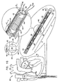
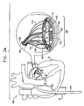
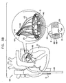
- Figs. 1A-F are schematic illustrations of a system 400 for repairing a mitral valve 30, being advanced into a left atrium of a patient, in accordance with an embodiment of the present invention.
- a catheter 404 ( Fig. 1B ) is advanced into the left atrium of the patient using a percutaneous endovascular approach typically combined with continuous monitoring by electromagnetic and/or sound waves, e.g., fluoroscopy, transesophageal echo, and/or echocardiography, to maintain real-time orientation of a distal tip of the catheter within the heart of the patient.
- catheter 404 is transseptally advanced into the left atrium.
- Catheter 404 typically comprises a 13 F catheter, although another size may be appropriate for a given patient.
- catheter 404 is advanced through vasculature of the patient and into the right atrium using a suitable point of origin typically determined for a given patient. For example:
- catheter 404 is advanced through an inferior vena cava 22 of the patient (as shown) and into the right atrium using a suitable point of origin typically determined for a given patient
- Fig. 1A shows a guide wire 402 being advanced into the right atrium of the patient. Advancement of wire 402 typically precedes advancement of catheter 404 into the right atrium of the patient
- Wire 402 comprises a semi-rigid wire which provides a guide for the subsequent advancement of catheter 404 therealong and into the right atrium of the patient, as shown in Fig. 1B .
- guide wire 402 is retracted and extracted from within the body of the patient ( Fig. 1C ).
- catheter 404 is pushed distally until it reaches the interatrial septum of heart 20 of the patient.
- proximal means closer to the orifice through which catheter 404 is originally placed into the vasculature of the patient, and “distal” means further from this orifice.
- a resilient needle 406 is advanced through catheter 404 and into heart 20 of the patient.
- needle 406 In order to advance catheter 404 transseptally into the left atrium, needle 406 first punctures the septum of heart 20 such that an opening is created which facilitates passage of catheter 404 therethrough and into the left atrium.
- a dilator (not shown) is advanced along needle 406 and toward the septum of heart 20.
- the dilator is shaped to define a hollow shaft for passage along needle 406, the hollow shaft being shaped to define a tapered distal end. This tapered distal end is first advanced through the hole created by needle 406.
- the hole is enlarged when the gradually increasing diameter of the distal end of the dilator is pushed through the hole in the septum.
- the advancement of catheter 404 through the septum and into the left atrium is followed by the extraction of the dilator from within catheter 404 ( Fig. 1F ).
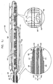
- Fig. 1G is a schematic illustration of a first segment 430 and a second segment 440 of an annuloplasty structure 408 being advanced along catheter 404, in accordance with an embodiment of the present invention.
- Segments 430 and 440 are configured to be chronically implanted within heart 20 along an annulus 40 of mitral valve 30.
- segments 430 and 440 comprise a biocompatible material, e.g., nitinol, titanium, silicone, polytetrafluoroethylene (PTFE), and/or polyester graft material.
- segments 430 and 440 comprise accordion-like, compressible subunits 450 which facilitate bending of the segments into a suitable configuration and compressing of the segments when they are later drawn toward one another.
- segments 430 and 440 comprise coils made of stainless steel, e.g., type 304 or type 316. Suitable coil shapes include round wire coils or flat wire coils.
- segments 430 and 440 Prior to advancing segments 430 and 440 into the left atrium of the patient, segments 430 and 440 are loaded into an advancement catheter 410 in a substantially linear configuration, as shown in Fig. 1G .
- the linear configuration defines a longitudinal axis of segments 430 and 440 of structure 408. Segments 430 and 440 are typically advanced into the left atrium of the patient during a single transcatheter advancement.
- segment 430 During advancement of segment 430 within advancement catheter 410, segment 430 has a length L1 between about 10 mm and about 50 mm, e.g., 20 mm. Length L1 of segment 430 typically corresponds with a portion of annulus 40 at the junction between annulus 40 and the base of the anteromedial leaflet of valve 30.
- second segment 440 is designated to be anchored to annulus 40 at the base of the posterolateral leaflet, and thus is sized in accordance therewith.
- segment 440 may have a length L2 of between about 20 mm and about 80 mm, e.g., 40 mm.
- segments 430 and 440 enable the segments to dynamically support the mitral valve in accordance with the relative motion of the anteromedial and posterolateral leaflets.
- segments 430 and 440 each have a diameter L3 of between about 1 mm and about 5 mm, typically between about 2.5 mm and about 3.5 mm.
- segments 430 and 440 are shaped to define a lateral wall 462 that has at least one flexible hollow lumen configured for sliding advancement of at least one control wire therethrough.
- a first control wire 480 and a second control wire 490 are disposed within both the first and second segments 430 and 440.
- wires 480 and 490 function to position and adjust a relative disposition and configuration of segments 430 and 440 with respect to a configuration of annulus 40 of valve 30.
- the structural and spatial configurations of each segment are controlled independently by a respective one of the first and second control wires 480 and 490. Such functions of wires 480 and 490 are described hereinbelow.
- control wires 480 and 490 e.g., between about 0.2 mm and about 0.4 mm, typically, between 0.25 mm and 0.3 mm
- control wires 480 and 490 comprise a resilient material capable of providing a pulling force to segments 430 and 440, e.g., nitinol or Teflon.
- control wires 430 and 440 are Teflon-coated.
- first and second control tubes are disposed within both the first and second segments.
- the first and second control tubes are configured to function similarly to control wires 480 and 490 described herein.
- lateral wall 462 of segments 430 and 440 is shaped to provide a first portion 464 and a second portion 466 generally at opposite sites of the segment when viewed in cross-section (e.g., at 12 o'clock and 6 o'clock).
- First and second segments 430 and 440 of annuloplasty structure 408 each comprise at least one channel 460.
- Channel 460 is configured to extend from first portion 464, through the given segment, to second portion 466.
- a respective flexible and longitudinal guide member 470 is partially disposed within each channel 460 and is used to facilitate anchoring of annuloplasty structure 408, as described hereinbelow.
- guide member 470 is configured to facilitate advancement therealong of a respective anchoring structure (described hereinbelow).
- the anchoring structure is typically advanced along guide member 470, through channel 460, and is ultimately anchored into annulus 40 of mitral valve 30, thereby anchoring the segment to annulus 40.
- guide member 470 comprises a flexible metal wire, e.g., nitinol or stainless steel.
- guide member 470 comprises a suture comprising an artificial fiber, e.g., nylon, polypropylene, Kevlar, Teflon, or polyester.
- each guide member 470 has a diameter of between about 0.05 mm and about 0.2 mm, e.g., 0.1 mm.
- advancement catheter 410 Prior to advancing segments 430 and 440 into the left atrium of the patient, advancement catheter 410 is preloaded with segments 430 and 440, with control wires 480 and 490, with guide members 470, and with a multilumen catheter 420 which is disposed proximally to segments 430 and 440. Thus, segments 430 and 440 are simultaneously conveyed toward heart 20, during a single transcatheter advancement.
- advancement catheter 410 comprises a 12 F catheter, although other sizes may be appropriate depending on the size of catheter 404.
- Figs. 1H and 1I show deployment of first segment 430 of the segmented annuloplasty ring, in accordance with an embodiment of the present invention.
- Segments 430 and 440 are in a linear configuration within advancement catheter 410 when catheter 410 is advanced within catheter 404 and initially enters the left atrium. As shown in Fig. 1H , a distal end of catheter 410 emerges from within catheter 404. Segment 430 maintains its linear configuration as it is initially pushed from within catheter 410.
- each guide member 470 is looped around a bar disposed within each channel 460.
- the purpose of this bar is described hereinbelow.
- first and second segments 430 and 440 of structure 408 are ultimately made to assume a somewhat round configuration that resembles an annuloplasty ring in structure and function.
- control wires 480 and 490 are tightly pulled proximally, applying a force to segment 430 and compressing segment 430 so that it is made to assume a curved configuration.
- the curved configuration is thus achieved as compressible subunits 450 are compressed in response to the pulling of control wires 480 and 490.
- compressible subunits 450 are compressed generally in parallel with the longitudinal axis of segment 430.
- Such a curved configuration minimizes the possibility for segment 430 to prematurely contact walls of heart 20: (1) during deployment of system 400 within the left atrium, and (2) prior to positioning segments 430 and 440 along annulus 40.
- segments 430 and 440 of annuloplasty structure 408 comprise a shape-memory alloy, e.g., nitinol.
- segments 430 and 440 are introduced within catheter 410 in a straight configuration, and are each biased to assume a generally semi-circular configuration once expanded from within catheter 410.
- Annuloplasty structure 408 thus assumes a somewhat round configuration typically independently of the application of a proximal force to control wires 430 and 440.
- control wires 430 and 440 are used instead to expand the segments by separating at least a part of segment 430 from at least a part of segment 440.
- FIG. 1J is a schematic illustration of system 400 comprising annuloplasty structure 408 and multilumen catheter 420, in accordance with an embodiment of the present invention.
- each control wire 480 and 490 is coupled to a respective adjustment wire 482 and 492.
- Adjustment wires 482 and 492 are configured to contribute to adjusting a relative disposition of segments 430 and 440 once inside the left atrium of heart 20. The functions of wires 482 and 492 are described in more detail hereinbelow.
- multilumen catheter 420 is shaped to define a primary lumen 426 and secondary lumens 422 and 424.
- the flexible and longitudinal guide members 470 are disposed within primary lumen 426 and are exposed outside the body of the patient proximally to catheter 404. Since, in some embodiments, a respective anchoring structure is advanced along each of guide members 470, primary lumen 426 typically has a diameter D1 of between about 1.0 mm to about 3.0 mm (e.g., 1.6 mm). The diameter D1 of lumen 426 allows passage therethrough of at least one anchoring structure at a given time.
- Multilumen catheter 420 separates and isolates control wire 480 from control wire 490 and separates and isolates adjustment wire 482 from adjustment wire 492, thereby enabling the physician to distinguish between each of control wires 480 and 490 and between adjustment wires 482 and 492.
- catheter 420 helps facilitate independent control by the physician of each of the wires which ultimately determine the relative positioning of structure 408 within the left atrium of heart 20.
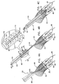
- FIGs. 2A and 2B are schematic illustrations of first segment 430 of structure 408 being advanced from within catheter 410, as described hereinabove with reference to Figs. 1H and 1I , in accordance with an embodiment of the present invention.
- FIG. 2C is a schematic illustration of the deployment and expansion of segments 430 and 440, in accordance with an embodiment of the present invention.
- Control wires 480 and 490 are shown disposed within at least one hollow lumen of both first and second segments 430 and 440 of annuloplasty structure 480, thereby coupling the segments.
- each of segments 430 and 440 is shaped to provide a first lumen configured for sliding advancement therethrough of wire 480, and a second lumen configured for sliding advancement of wire 490 (configuration not shown).
- First and second portions of control wire 480 emerge from within segments 430 and 440 at respective first ends 432 and 442 of segments 430 and 440.
- control wire 480 are disposed within secondary lumen 424 such that first and second ends of wire 480 are exposed and controllable from outside the body of the patient.
- first and second portions of control wire 490 emerge from within segments 430 and 440 at respective second ends 434 and 444 of segment 430 and 440.
- the first and second portions of control wire 490 are disposed within secondary lumen 422, such that first and second ends of wire 490 are exposed and controllable from outside the body of the patient.
- multilumen catheter 420 is shaped to provide secondary lumens 423 and 425, as shown.
- lumens 423 and 425 are provided for passage of supplementary instruments, e.g., for suction and/or irrigation, therethrough and into the left atrium of the patient.
- Adjustment wire 482 extends from secondary lumen 422 and is coupled at a distal end thereof to control wire 480. Typically, adjustment wire 482 is coupled to a portion of wire 480 that is disposed at a junction between respective second ends 434 and 444 of segments 430 and 440.
- adjustment wire 492 extends from secondary lumen 424 and is coupled at a distal end thereof to control wire 490. Typically, adjustment wire 492 is coupled to a portion of control wire 490 that is disposed at a junction between respective first ends 432 and 442 of segments 430 and 440.
- adjustment wires 482 and 492 are irreversibly coupled, e.g. knotted or otherwise fixed, to control wires 480 and 490, respectively. In some embodiments, adjustment wires 482 and 492 are looped around control wires 480 and 490, respectively.
- the separating of segments 430 and 440 occurs when the physician pushes control wires 480 and 490 while pushing adjustment wires 482 and 492.
- adjustment wires 482 and 492 provide an auxiliary pushing force which helps expand segments 430 and 440.
- Such pushing of the control wires feeds greater portions of control wires 480 and 490 into segments 430 and 440.
- the relaxed configuration of control wires 480 and 490 is shown in Fig. 2C
- the taut configuration thereof is shown in Fig. 2B .
- segments 430 and 440 expand annularly as increasing lengths of control wires 480 and 490 are pushed and fed into segments 430 and 440.
- adjustment wires 482 and 492 are pulled to elevate portions of segments 430 and 440, such that the segments conform to the shape of annulus 40.
- pulling adjustment wire 482 elevates the portion of control wire 480 which is disposed between segments 430 and 440.
- second ends 434 and 444 of segments 430 and 440, respectively, are elevated.
- Control wires 480 and 490 enable the physician to control a relative disposition of second ends 434 and 444 and first ends 432 and 442 of segments 430 and 440, respectively. For example, distal pushing of the first and second ends of control wire 480 distances second ends 434 and 444 of segments 430 and 440, respectively. Similarly, distal pushing of the first and second ends of control wire 490 distances first ends 432 and 442 of segments 430 and 440, respectively. It is to be noted that the use of two discrete control wires allows for independent control of the distance that separates first ends 432 and 442 and the distance that separates second ends 434 and 444 of segments 430 and 440.
- control wires 480 and 490 shapes segments 430 and 440 in accordance with the curved structural conformation of annulus 40 at a given site destined for anchoring of a respective one of the segments thereto. For example, pulling on a first end of control wire 490 and on a first end of control wire 480 curves segment 430 by drawing together second end 432 and first end 434, respectively, of segment 430. Thus, segment 430 is compressed at least in part, and is made to assume a shape according to the curvature of the annulus at the base of the anteromedial leaflet.
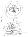
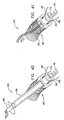
- Fig. 2D is a schematic illustration of the deployment and expansion of segments 430 and 440 as described hereinabove with reference to Fig. 2C , with the exception that structure 408 is optionally rotated as appropriate about an axis of annulus 40, in accordance with an embodiment of the present invention.
- the physician assesses the relative disposition of segments 430 and 440 with respect to annulus 40 of heart 20.
- Multilumen catheter 420 is configured to be rotatable 360 degrees about a longitudinal axis thereof. By rotating multilumen catheter 420, the segments are positioned properly with respect to the annulus. That is, segment 440 is positioned above a portion of annulus 40 at the base of the posterolateral leaflet, while segment 430 is positioned above a portion of annulus 40 at the base of the anteromedial leaflet.
- Fig. 2E shows catheter 410 comprising a steering wire 500, in accordance with an embodiment of the present invention.
- a distal end of steering wire 500 is coupled to a distal end of catheter 410.
- a proximal end of wire 500 is disposed at a site outside the body of the patient, enabling the physician to steer the distal end of catheter 410.
- multilumen catheter 420 is retracted slightly within advancement catheter 410. Retracting multilumen catheter 420 frees the lumen of the distal end of catheter 410, thereby restoring flexibility to the distal end of catheter 410 and enabling proper steering thereof.
- Structure 408 is pushed toward annulus 40 by pushing on both catheter 410 and on wires 480 and 490. Additionally, the structure is.properly aligned with annulus 40 by steering and/or rotating the distal tip of catheter 410.
- Fig. 2F shows system 400 following the aligning of segments 430 and 440 with annulus 40, in accordance with an embodiment of the present invention.
- Segment 440 is aligned against the base of posterolateral leaflet 32 at the annulus
- segment 430 is aligned against the base of anteromedial leaflet 34 at the annulus.
- Segments 430 and 440 are shown prior to anchoring thereof to annulus 40.
- Multilumen catheter 420 is shown in a slightly retracted state within catheter 410.
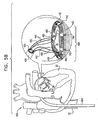
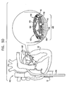
- Figs. 3A and 3B are schematic illustrations of system 400 comprising an anchoring system 600, in accordance with an embodiment of the present invention.
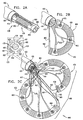
- Fig. 4A shows a bar 710 disposed within channel 460.
- bar 710 is disposed perpendicularly to an axis of channel 460, and at the base of the channel. It is to be noted that bar 710 is disposed parallel to the longitudinal axis of segment 440 (or segment 430) by way of illustration and not limitation. For example, bar 710 may be disposed perpendicularly to the axis of segment 440.
- Guide member 470 is disposed within channel 460 and is reversibly coupled to structure 408 via bar 710.
- guide member 470 is looped around bar 710 prior to the advancement of structure 408 into the body of the patient.
- both ends of guide member 470 are exposed outside the body of the patient, thus enabling the physician to slide anchoring system 600 around both ends of member 470 and therealong toward annulus 40 of heart 20.
- Fig. 4B shows anchoring system 600 comprising an outer tube 610 housing an advancement tube 620, which is reversibly coupled to an anchoring structure 740.
- anchoring structure 740 comprises a helical element whose proximal end is tightly wrapped around a distal end of advancement tube 620.
- Outer tube 610 typically prevents radial expansion of anchoring structure 740 within primary lumen 426 of multilumen catheter 420 as element 740 is advanced therein.
- Anchoring system 600 is advanced within channel 460, as shown in Fig. 4C .
- Anchoring of anchoring structure 740 begins when the physician rotates advancement tube 620 about a longitudinal axis thereof. Such rotation corkscrews a distal portion of the helical element around and beyond bar 710 and subsequently into annulus 40 of the patient.
- channel 460 has a diameter D2, e.g., between about 0.8 mm and 1.2 mm, typically 1.0 mm. Diameter D2 is thus sized in order to enable passage of anchoring structure 740 through channel 460.
- anchoring structure 740 has a diameter D3 of between about 0.5 mm and 1.5 mm, e.g., 1 mm.
- each coil of the coiled, helical element has a diameter D4 of between about 0.05 mm and 0.5 mm, e.g., 0.2 mm.
- the helical element is shaped to define at least two adjacent distal rotational subunits 720 and at least two adjacent proximal rotational subunits 730.
- a distance Di1 e.g., between about 0.3 mm and about 0.6 mm
- a distance Di2 e.g., between about 0 mm and about 0.4 mm
- a diameter of bar 710 is less than distance Di1 and greater than distance Di2.
- Distance Di1 enables distal rotational subunits 720 to be corkscrewed around bar 710 and subsequently into annulus 40 of the patient.
- Distance Di2 is typically less than a diameter of bar 710, and therefore restricts proximal rotational subunits 730 from being corkscrewed fully around bar 710 and into annulus 40.
- bar 710 restricts the rotation of subunits 730 therearound and applies a counterforce to a torque applied by rotation of tube 620.
- the counterforce applied by bar 710 expands proximal subunits 730 radially such that subunits 730 are no longer wrapped tightly around the distal end of tube 620.
- anchoring structure 740 is released from tube 620, typically by pulling on tube 620 while continuing to apply a rotational, helix-expanding force to proximal subunits 730.
- Tube 620 is then pulled proximally along guide member 470 and extracted from within the body of the patient, as shown in Fig. 4E .
- guide member 470 typically remains within system 400, although it is optionally removed at the same time as tube 620.
- a few rotational subunits of the helical element are wrapped around a distal end of tube 620, while the remaining rotational subunits extend distally from the distal end of tube 620.
- a smaller number of rotational subunits are wrapped around tube 620 than the number of rotational subunits that extend distally from the distal end of tube 620 and are not wrapped around the distal end of tube 620.
- three rotational subunits are wrapped around the distal end of tube 620, while four rotational subunits are disposed distally to the distal end of tube 620.
- the rotational subunits wrapped around the distal end of tube 620 generally provide enough frictional force to maintain their position around the distal end of tube 620.
- a protrusion (not shown) is typically disposed along the distal end of tube 620 adjacent to the proximal-most tip of the helical element of anchoring structure 740.
- the protrusion applies a circumferentially-directed pushing force to the proximal-most tip of the helical element.
- the protrusion typically adds to the frictional force described above, in order to rotate anchoring structure 740.
- One or both of these forces enable a distal end of structure 740 to puncture annulus 40.
- the proximal end of anchoring structure 740 slides distally along the distal end of tube 620 and away from the protrusion.
- the distal end of tube 620 is impeded by bar 710.
- the physician continues to rotate tube 620 such that the proximal-most tip of anchoring structure 740 continues to slide distally from the protrusion while the entire anchoring structure 740 continues to be advanced distally within tissue of annulus 40.
- fewer rotational subunits are wrapped around the distal end of tube 620, thereby reducing friction between anchoring structure 740 and the distal end of tube 620.
- the minimal friction between structure 740 and the distal end of tube 620 enables the physician to pull on tube 620 in order to detach tube 620 from anchoring structure 740.
- anchoring structure 740 may comprise a screw, harpoon, barb, or any other anchoring structure known in the art.
- anchoring structure 740 comprises a wire configured to penetrate annulus 40 in a generally straight configuration and to subsequently assume a curved configuration once inside tissue of annulus 40.
- FIGs. 5A-B are schematic illustrations of anchoring system 600, which anchors segments 430 and 440 to annulus 40 of heart 20, in accordance with an embodiment of the present invention.
- Fig. 5A shows segment 440 being anchored, via anchoring system 600, to annulus 40 at the base of posterolateral leaflet 32.
- a respective anchoring system 600 is sequentially advanced along each guide member 470 until both segments 430 and 440 are anchored to annulus 40, and tubes 620 and guide members 470 are withdrawn.
- the helical element of anchoring structure 740 comprises a pointed distal tip 750 configured to puncture tissue of annulus 40 in order to enable screwing of structure 740 within annulus 40 of the patient.
- distal tip 750 comprises a barb or anchoring structure 740 comprises a plurality of barbs, configured to provide a lock between structure 740 and annulus 40.
- each guide member 470 is decoupled from the respective bar 710.
- guide member 470 is decoupled from bar 710 when the physician pulls on a first end of guide member 470 from a site outside the body of the patient.
- Guide member 470 slides around bar 710 until it is extracted from within the body of the patient.
- a first end of guide member 470 comprises a material configured to dissolve when exposed within heart 20 of the patient.
- guide member 470 is typically not looped around bar 710, rather, it is coupled at its first end to bar 710 while a second end thereof is disposed outside the body of the patient Following anchoring of structure 740 to annulus 40 as described hereinabove, the first end of guide member 470 dissolves, thereby decoupling guide member 470 from bar 710.
- Guide member 470 is then pulled from its second end until the first end is extracted from within the body of the patient.
- a first end of guide member 470 is coupled to one of the segments, prior to placement in the patient's body, by, for example, passing through channel 460 and being attached to an external surface of the segment.
- guide member 470 comprises a "T"-shaped anchor at a distal end of guide member 470, which passes through channel 460 and inhibits proximal motion of the "T"-shaped anchor through the channel.
- guide member 470 is typically not looped around bar 710.
- a second end of guide member 470 is disposed outside the body of the patient.
- guide member 470 Following anchoring of structure 740 to annulus 40 as described hereinabove, the physician pulls on the second end of guide member 470 in order to tear the guide member at a pre-weakened point on the guide member, typically slightly proximal to the segment. Guide member 470 is then extracted from within the body of the patient while the distal-most portion of guide member 470 that is attached to the external surface of the segment, or the "T"-shaped anchor, remains disposed within structure 408.
- FIG. 5C is a schematic illustration of system 400, comprising a tensile suture 800 configured for sliding advancement through segments 430 and 440, in accordance with an embodiment of the present invention.
- One of control wires 480 or 490 e.g., control wire 480
- the physician replaces control wire 490 with tensile suture 800 by (a) tying a first end of suture 800 to a first end of wire 490, and then (b) pulling on a second end of wire 490.
- Tensile suture 800 comprises a flexible material, e.g., nitinol, Kevlar, titanium, or polytetrafluoroethylene (PTFE), and is configured to reside chronically within segments 430 and 440.
- suture 800 may comprise a braided polyester suture (e.g., Ticron).
- suture 800 is configured to withstand cardiac pressures and constant motion of segments 430 and 440 that result from the motion of annulus 40.
- suture 800 typically has a relatively thick diameter of between about 0.1 mm and about 1.0 mm, typically between about 0.3 mm and about 0.6 mm.
- two tensile sutures 800 reside chronically within segments 430 and 440.
- a first tensile suture replaces control wire 480
- a second tensile suture replaces control wire 490.
- Control wires 480 and 490 are replaced as described hereinabove.
- first and second ends of suture(s) 800 are pulled to an extent that is based on (a) the level of dilation of the preoperative mitral valve, and/or (b) real-time monitoring of regurgitation minimization.
- Fig. 5C shows a lock 820 being advanced around first and second portions of suture 800, in accordance with an embodiment of the present invention.
- Lock 820 secures together segments 430 and 440 of annuloplasty structure 408, thereby defining its final configuration within annulus 40 of mitral valve 30.
- the excess portions of tensile suture 800 are clipped proximally to lock 820 and are extracted from the body via catheter 404. Following clipping, first and second ends of suture 800 remain accessible for future tightening together of segments 430 and 440 upon need therefor.
- the first and second ends of suture 800 are located using fluoroscopy or any other method described herein.
- Fig. 5D shows annuloplasty structure 408 in a closed state, in accordance with an embodiment of the present invention.
- guide members 470 comprise a screw at a distal end thereof.
- Guide member 470 in this embodiment is suitable for conveying torque, such that by rotating the proximal end of the guide member from outside the body of the patient, the screw at the distal end is screwed into the annulus. Following anchoring of the screw to the annulus of the patient, the guide member is clipped proximally to the screw and is extracted from within the body of the patient.
- guide member 470 is configured to anchor structure 408 to annulus 40 independently of bar 710 described hereinabove.
- the scope of the present invention is not limited to minimally-invasive procedures (e.g., transcatheter procedures such as percutaneous or intercostal penetration procedures), and includes applications in which system 400 is applied in invasive procedures such as open heart surgery.
- system 400 may be used to treat valves other than mitral valve 30.
- system 400 may be used to treat an aortic valve of the patient.
Landscapes
- Health & Medical Sciences (AREA)
- Cardiology (AREA)
- Life Sciences & Earth Sciences (AREA)
- Engineering & Computer Science (AREA)
- Public Health (AREA)
- Biomedical Technology (AREA)
- Heart & Thoracic Surgery (AREA)
- Surgery (AREA)
- Veterinary Medicine (AREA)
- Animal Behavior & Ethology (AREA)
- General Health & Medical Sciences (AREA)
- Vascular Medicine (AREA)
- Oral & Maxillofacial Surgery (AREA)
- Nuclear Medicine, Radiotherapy & Molecular Imaging (AREA)
- Transplantation (AREA)
- Medical Informatics (AREA)
- Molecular Biology (AREA)
- Prostheses (AREA)
Claims (11)
- Vorrichtung zum Reparieren einer Klappe (30) eines Herzens eines Patienten, wobei die Klappe (30) einen Anulus (40) und mindestens ein erstes und ein zweites Klappensegel (32, 34) umfasst, wobei die Vorrichtung Folgendes umfasst:eine Anuloplastikstruktur (408);mehrere Gewebeanker (740);mehrere biegsame längslaufende Führungsglieder (470), die abnehmbar an die Anuloplastikstruktur (408) gekoppelt sind, wobei die Führungsglieder (470) jeweils dazu ausgebildet sind, das Verankern der Anuloplastikstruktur (408) am Anulus des Patienten durch einen entsprechenden der Anker (740) zu ermöglichen, und die Führungsglieder (470) dazu ausgebildet sind, gleichzeitig mit der Anuloplastikstruktur (408) zu dem Anulus voranbewegt zu werden,wobei die Vorrichtung dadurch gekennzeichnet ist, dass die Anuloplastikstruktur (408) mindestens ein erstes und ein zweites diskretes Segment (430, 440) eines Anuloplastikrings umfasst, wobei das erste und das zweite diskrete Segment (430, 440) jeweils dazu gestaltet sind, mindestens ein längslaufendes Lumen des entsprechenden Segments (430, 440) zu definieren, wobei das erste und das zweite Segment (430, 440) dazu ausgebildet sind, in einer allgemein geraden Ausbildung zu dem Vorhof des Herzens des Patienten voranbewegt zu werden, wobei die gerade Ausbildung eine längslaufende Achse des ersten bzw. des zweiten Segments (430, 440) definiert,wobei die Vorrichtung weiter mindestens einen ersten und einen zweiten Steuerdraht (480, 490) umfasst, wobei die Steuerdrähte (480, 490) jeweils für das gleitende Voranbewegen durch die Lumen des ersten und des zweiten Segments (430, 440) ausgebildet sind,wobei der erste Steuerdraht (480) dazu ausgebildet ist, eine relative Anordnung eines ersten Endes (432) des ersten Segments (430) und eines ersten Endes (442) des zweiten Segments (440) zu steuern, und der zweite Steuerdraht (490) dazu ausgebildet ist, eine relative Anordnung eines zweiten Endes (434) des ersten Segments (430) und eines zweiten Endes (444) des zweiten Segments (440) zu steuern, wobei der erste und der zweite Steuerdraht (480, 490) weiter dazu ausgebildet sind, eine relative Anordnung des ersten und des zweiten Segments (430, 440) zu steuern,und wobei mindestens ein Abschnitt des ersten und des zweiten Segments (430, 440) dazu gestaltet ist, eine oder mehrere zusammendrückbare Einheiten (450) zu definieren, die das Biegen der Segmente in eine geeignete Ausbildung und das Zusammendrücken der Segmente, wenn sie aufeinander zu gezogen werden, ermöglichen, wobei die zusammendrückbaren Einheiten (450) dazu ausgebildet sind, parallel zu der längslaufenden Achse der entsprechenden Segmente (430, 440) zusammengedrückt zu werden.
- Vorrichtung nach Anspruch 1, wobei der erste und der zweite Steuerdraht (480, 490) dazu ausgebildet sind, das erste und das zweite Segment (430, 440) zu trennen.
- Vorrichtung nach Anspruch 1, wobei die zusammendrückbaren Einheiten (450) dazu ausgebildet sind, als Reaktion auf ein Ausüben einer Zugkraft auf den ersten und den zweiten Steuerdraht (480, 490) zusammengedrückt zu werden.
- Vorrichtung nach Anspruch 1, wobei der erste Steuerdraht (480) dazu ausgebildet ist, das erste Segment (430) mindestens teilweise als Reaktion auf ein Ausüben einer Zugkraft auf mindestens einen Abschnitt des ersten Steuerdrahts (480) zusammenzudrücken, und wobei der zweite Steuerdraht (490) dazu ausgebildet ist, das zweite Segment (440) mindestens teilweise als Reaktion auf ein Ausüben einer Zugkraft auf mindestens einen Abschnitt des zweiten Steuerdrahts (490) zusammenzudrücken.
- Vorrichtung nach Anspruch 1, wobei die Anuloplastikstruktur (408) dazu gestaltet ist, eine laterale Wand mit einem ersten und einem zweiten Abschnitt zu definieren und mehrere Kanäle (460) vorzusehen, wobei sich die Kanäle (460) jeweils von dem ersten Abschnitt der lateralen Wand zu dem zweiten Abschnitt der lateralen Wand der Struktur erstrecken.
- Vorrichtung nach Anspruch 5, weiter umfassend mehrere Stäbe (710), wobei die mehreren Stäbe (710) jeweils dazu ausgebildet sind, innerhalb von einem entsprechenden der mehreren Kanäle (460) angeordnet zu sein.
- Vorrichtung nach Anspruch 6, wobei:die Anker (740) jeweils ein spiralförmiges Element umfassen, das dazu ausgebildet ist, korkenzieherartig mindestens teilweise in den Anulus des Patienten eingeschraubt zu werden,das spiralförmige Element dazu gestaltet ist, mindestens zwei benachbarte distale Drehungs-Untereinheiten und mindestens zwei benachbarte proximale Drehungs-Untereinheiten zu definieren, undein Abstand zwischen den zwei benachbarten distalen Drehungs-Untereinheiten größer ist als ein Abstand zwischen den zwei benachbarten proximalen Drehungs-Untereinheiten.
- Vorrichtung nach Anspruch 7, wobei der Abstand zwischen den proximalen Drehungs-Untereinheiten die proximalen Drehungs-Untereinheiten daran hindert, korkenzieherartig um den Stab (710) und in den Anulus des Patienten geschraubt zu werden.
- Vorrichtung nach Anspruch 1, wobei die mehreren längslaufenden Führungsglieder (470) entsprechende mehrere Suturen umfassen.
- Vorrichtung nach Anspruch 1, wobei die mehreren Längsführungsglieder (470) entsprechende mehrere Drähte umfassen.
- Vorrichtung nach Anspruch 1, wobei die Anuloplastikstruktur für das Voranbewegen durch einen Katheter zu dem Herz eines Patienten ausgebildet ist.
Applications Claiming Priority (4)
| Application Number | Priority Date | Filing Date | Title |
|---|---|---|---|
| US87307506P | 2006-12-05 | 2006-12-05 | |
| US90214607P | 2007-02-16 | 2007-02-16 | |
| US101307P | 2007-10-29 | 2007-10-29 | |
| PCT/IL2007/001503 WO2008068756A2 (en) | 2006-12-05 | 2007-12-05 | Segmented ring placement |
Publications (3)
| Publication Number | Publication Date |
|---|---|
| EP2088965A2 EP2088965A2 (de) | 2009-08-19 |
| EP2088965A4 EP2088965A4 (de) | 2011-03-02 |
| EP2088965B1 true EP2088965B1 (de) | 2012-11-28 |
Family
ID=39492723
Family Applications (1)
| Application Number | Title | Priority Date | Filing Date |
|---|---|---|---|
| EP07849540A Not-in-force EP2088965B1 (de) | 2006-12-05 | 2007-12-05 | Platzierung eines segmentierten Rings |
Country Status (6)
| Country | Link |
|---|---|
| US (2) | US8926695B2 (de) |
| EP (1) | EP2088965B1 (de) |
| JP (1) | JP2010511469A (de) |
| AU (1) | AU2007330338A1 (de) |
| CA (1) | CA2671966A1 (de) |
| WO (1) | WO2008068756A2 (de) |
Cited By (25)
| Publication number | Priority date | Publication date | Assignee | Title |
|---|---|---|---|---|
| US9351830B2 (en) | 2006-12-05 | 2016-05-31 | Valtech Cardio, Ltd. | Implant and anchor placement |
| US9974647B2 (en) | 2014-06-12 | 2018-05-22 | Caisson Interventional, LLC | Two stage anchor and mitral valve assembly |
| US9974653B2 (en) | 2006-12-05 | 2018-05-22 | Valtech Cardio, Ltd. | Implantation of repair devices in the heart |
| US10080656B2 (en) | 2012-04-19 | 2018-09-25 | Caisson Interventional Llc | Heart valve assembly systems and methods |
| US10117741B2 (en) | 2013-10-23 | 2018-11-06 | Caisson Interventional, LLC | Methods and systems for heart valve therapy |
| US10231831B2 (en) | 2009-12-08 | 2019-03-19 | Cardiovalve Ltd. | Folding ring implant for heart valve |
| US10265166B2 (en) | 2015-12-30 | 2019-04-23 | Caisson Interventional, LLC | Systems and methods for heart valve therapy |
| US10285810B2 (en) | 2012-04-19 | 2019-05-14 | Caisson Interventional, LLC | Valve replacement systems and methods |
| US10856984B2 (en) | 2017-08-25 | 2020-12-08 | Neovasc Tiara Inc. | Sequentially deployed transcatheter mitral valve prosthesis |
| US10940001B2 (en) | 2012-05-30 | 2021-03-09 | Neovasc Tiara Inc. | Methods and apparatus for loading a prosthesis onto a delivery system |
| US11311376B2 (en) | 2019-06-20 | 2022-04-26 | Neovase Tiara Inc. | Low profile prosthetic mitral valve |
| US11357622B2 (en) | 2016-01-29 | 2022-06-14 | Neovase Tiara Inc. | Prosthetic valve for avoiding obstruction of outflow |
| US11389291B2 (en) | 2013-04-04 | 2022-07-19 | Neovase Tiara Inc. | Methods and apparatus for delivering a prosthetic valve to a beating heart |
| US11413139B2 (en) | 2011-11-23 | 2022-08-16 | Neovasc Tiara Inc. | Sequentially deployed transcatheter mitral valve prosthesis |
| US11419720B2 (en) | 2010-05-05 | 2022-08-23 | Neovasc Tiara Inc. | Transcatheter mitral valve prosthesis |
| US11439506B2 (en) | 2014-10-23 | 2022-09-13 | Caisson Interventional Llc | Systems and methods for heart valve therapy |
| US11464631B2 (en) | 2016-11-21 | 2022-10-11 | Neovasc Tiara Inc. | Methods and systems for rapid retraction of a transcatheter heart valve delivery system |
| US11491006B2 (en) | 2019-04-10 | 2022-11-08 | Neovasc Tiara Inc. | Prosthetic valve with natural blood flow |
| US11497602B2 (en) | 2012-02-14 | 2022-11-15 | Neovasc Tiara Inc. | Methods and apparatus for engaging a valve prosthesis with tissue |
| US11602429B2 (en) | 2019-04-01 | 2023-03-14 | Neovasc Tiara Inc. | Controllably deployable prosthetic valve |
| US11737872B2 (en) | 2018-11-08 | 2023-08-29 | Neovasc Tiara Inc. | Ventricular deployment of a transcatheter mitral valve prosthesis |
| US11779742B2 (en) | 2019-05-20 | 2023-10-10 | Neovasc Tiara Inc. | Introducer with hemostasis mechanism |
| US11844691B2 (en) | 2013-01-24 | 2023-12-19 | Cardiovalve Ltd. | Partially-covered prosthetic valves |
| US11998447B2 (en) | 2019-03-08 | 2024-06-04 | Neovasc Tiara Inc. | Retrievable prosthesis delivery system |
| US12109111B2 (en) | 2015-12-15 | 2024-10-08 | Neovasc Tiara Inc. | Transseptal delivery system |
Families Citing this family (258)
| Publication number | Priority date | Publication date | Assignee | Title |
|---|---|---|---|---|
| WO2006097931A2 (en) | 2005-03-17 | 2006-09-21 | Valtech Cardio, Ltd. | Mitral valve treatment techniques |
| US8951285B2 (en) | 2005-07-05 | 2015-02-10 | Mitralign, Inc. | Tissue anchor, anchoring system and methods of using the same |
| US7749249B2 (en) | 2006-02-21 | 2010-07-06 | Kardium Inc. | Method and device for closing holes in tissue |
| US8449605B2 (en) | 2006-06-28 | 2013-05-28 | Kardium Inc. | Method for anchoring a mitral valve |
| US7837610B2 (en) | 2006-08-02 | 2010-11-23 | Kardium Inc. | System for improving diastolic dysfunction |
| JP2010511469A (ja) | 2006-12-05 | 2010-04-15 | バルテック カーディオ,リミティド | セグメント化リング配置 |
| US11259924B2 (en) | 2006-12-05 | 2022-03-01 | Valtech Cardio Ltd. | Implantation of repair devices in the heart |
| US9192471B2 (en) | 2007-01-08 | 2015-11-24 | Millipede, Inc. | Device for translumenal reshaping of a mitral valve annulus |
| US11660190B2 (en) | 2007-03-13 | 2023-05-30 | Edwards Lifesciences Corporation | Tissue anchors, systems and methods, and devices |
| CN103393485B (zh) | 2007-09-07 | 2016-08-10 | 爱德华兹生命科学公司 | 用于输送瓣环成形术环的活动支架 |
| US8349002B2 (en) * | 2008-01-16 | 2013-01-08 | QuickRing Medical Technologies, Ltd. | Adjustable annuloplasty rings |
| US8382829B1 (en) | 2008-03-10 | 2013-02-26 | Mitralign, Inc. | Method to reduce mitral regurgitation by cinching the commissure of the mitral valve |
| US20090287304A1 (en) | 2008-05-13 | 2009-11-19 | Kardium Inc. | Medical Device for Constricting Tissue or a Bodily Orifice, for example a mitral valve |
| EP2344075B1 (de) * | 2008-09-19 | 2018-12-05 | Edwards Lifesciences Corporation | Annuloplastiering für die aufnahme einer perkutanen herzklappenprothesenimplantation |
| US20100152844A1 (en) * | 2008-12-15 | 2010-06-17 | Couetil Jean-Paul A | Annuloplasty ring with directional flexibilities and rigidities to assist the mitral annulus dynamics |
| US8147542B2 (en) | 2008-12-22 | 2012-04-03 | Valtech Cardio, Ltd. | Adjustable repair chords and spool mechanism therefor |
| US8911494B2 (en) | 2009-05-04 | 2014-12-16 | Valtech Cardio, Ltd. | Deployment techniques for annuloplasty ring |
| US9011530B2 (en) | 2008-12-22 | 2015-04-21 | Valtech Cardio, Ltd. | Partially-adjustable annuloplasty structure |
| US8808368B2 (en) | 2008-12-22 | 2014-08-19 | Valtech Cardio, Ltd. | Implantation of repair chords in the heart |
| CN102341063B (zh) | 2008-12-22 | 2015-11-25 | 瓦尔泰克卡迪欧有限公司 | 可调瓣环成形装置及其调节机构 |
| US8241351B2 (en) | 2008-12-22 | 2012-08-14 | Valtech Cardio, Ltd. | Adjustable partial annuloplasty ring and mechanism therefor |
| US10517719B2 (en) | 2008-12-22 | 2019-12-31 | Valtech Cardio, Ltd. | Implantation of repair devices in the heart |
| US8940044B2 (en) * | 2011-06-23 | 2015-01-27 | Valtech Cardio, Ltd. | Closure element for use with an annuloplasty structure |
| US8926697B2 (en) | 2011-06-23 | 2015-01-06 | Valtech Cardio, Ltd. | Closed band for percutaneous annuloplasty |
| US8715342B2 (en) | 2009-05-07 | 2014-05-06 | Valtech Cardio, Ltd. | Annuloplasty ring with intra-ring anchoring |
| US8353956B2 (en) | 2009-02-17 | 2013-01-15 | Valtech Cardio, Ltd. | Actively-engageable movement-restriction mechanism for use with an annuloplasty structure |
| EP2416739B1 (de) | 2009-04-10 | 2016-06-08 | Lon Sutherland Annest | Impantierbares gerüst mit einer öffnung für eine klappenprothese bzw. bioklappenprothese |
| US9011522B2 (en) * | 2009-04-10 | 2015-04-21 | Lon Sutherland ANNEST | Device and method for temporary or permanent suspension of an implantable scaffolding containing an orifice for placement of a prosthetic or bio-prosthetic valve |
| US9968452B2 (en) | 2009-05-04 | 2018-05-15 | Valtech Cardio, Ltd. | Annuloplasty ring delivery cathethers |
| US12485010B2 (en) | 2009-05-07 | 2025-12-02 | Edwards Lifesciences Innovation (Israel) Ltd. | Multiple anchor delivery tool |
| US8523881B2 (en) * | 2010-07-26 | 2013-09-03 | Valtech Cardio, Ltd. | Multiple anchor delivery tool |
| US20110082538A1 (en) | 2009-10-01 | 2011-04-07 | Jonathan Dahlgren | Medical device, kit and method for constricting tissue or a bodily orifice, for example, a mitral valve |
| US10098737B2 (en) | 2009-10-29 | 2018-10-16 | Valtech Cardio, Ltd. | Tissue anchor for annuloplasty device |
| WO2011154942A2 (en) | 2010-06-07 | 2011-12-15 | Valtech Cardio, Ltd. | Apparatus and method for guide-wire based advancement of a rotation assembly |
| US9011520B2 (en) | 2009-10-29 | 2015-04-21 | Valtech Cardio, Ltd. | Tissue anchor for annuloplasty device |
| US8277502B2 (en) | 2009-10-29 | 2012-10-02 | Valtech Cardio, Ltd. | Tissue anchor for annuloplasty device |
| US9180007B2 (en) | 2009-10-29 | 2015-11-10 | Valtech Cardio, Ltd. | Apparatus and method for guide-wire based advancement of an adjustable implant |
| US8940042B2 (en) | 2009-10-29 | 2015-01-27 | Valtech Cardio, Ltd. | Apparatus for guide-wire based advancement of a rotation assembly |
| US8734467B2 (en) | 2009-12-02 | 2014-05-27 | Valtech Cardio, Ltd. | Delivery tool for implantation of spool assembly coupled to a helical anchor |
| US9307980B2 (en) | 2010-01-22 | 2016-04-12 | 4Tech Inc. | Tricuspid valve repair using tension |
| US10058323B2 (en) | 2010-01-22 | 2018-08-28 | 4 Tech Inc. | Tricuspid valve repair using tension |
| US8961596B2 (en) * | 2010-01-22 | 2015-02-24 | 4Tech Inc. | Method and apparatus for tricuspid valve repair using tension |
| US8475525B2 (en) | 2010-01-22 | 2013-07-02 | 4Tech Inc. | Tricuspid valve repair using tension |
| ES2761298T3 (es) | 2010-03-05 | 2020-05-19 | Edwards Lifesciences Corp | Mecanismos de retención para válvulas protésicas |
| US20110224785A1 (en) | 2010-03-10 | 2011-09-15 | Hacohen Gil | Prosthetic mitral valve with tissue anchors |
| US8790394B2 (en) | 2010-05-24 | 2014-07-29 | Valtech Cardio, Ltd. | Adjustable artificial chordeae tendineae with suture loops |
| US9050066B2 (en) | 2010-06-07 | 2015-06-09 | Kardium Inc. | Closing openings in anatomical tissue |
| JP5848345B2 (ja) | 2010-07-09 | 2016-01-27 | ハイライフ エスエーエス | 経カテーテル式房室弁人工器官 |
| US8657872B2 (en) | 2010-07-19 | 2014-02-25 | Jacques Seguin | Cardiac valve repair system and methods of use |
| US8992604B2 (en) | 2010-07-21 | 2015-03-31 | Mitraltech Ltd. | Techniques for percutaneous mitral valve replacement and sealing |
| US9763657B2 (en) | 2010-07-21 | 2017-09-19 | Mitraltech Ltd. | Techniques for percutaneous mitral valve replacement and sealing |
| US9132009B2 (en) | 2010-07-21 | 2015-09-15 | Mitraltech Ltd. | Guide wires with commissural anchors to advance a prosthetic valve |
| US11653910B2 (en) | 2010-07-21 | 2023-05-23 | Cardiovalve Ltd. | Helical anchor implantation |
| WO2012019052A2 (en) | 2010-08-04 | 2012-02-09 | Micardia Corporation | Percutaneous transcatheter repair of heart valves |
| US20120053680A1 (en) | 2010-08-24 | 2012-03-01 | Bolling Steven F | Reconfiguring Heart Features |
| CN103179920B (zh) * | 2010-08-24 | 2015-11-25 | 爱德华兹生命科学公司 | 具有选择控制点的柔性瓣膜成形环 |
| US9579193B2 (en) * | 2010-09-23 | 2017-02-28 | Transmural Systems Llc | Methods and systems for delivering prostheses using rail techniques |
| US8940002B2 (en) | 2010-09-30 | 2015-01-27 | Kardium Inc. | Tissue anchor system |
| US8888843B2 (en) | 2011-01-28 | 2014-11-18 | Middle Peak Medical, Inc. | Device, system, and method for transcatheter treatment of valve regurgitation |
| US8845717B2 (en) | 2011-01-28 | 2014-09-30 | Middle Park Medical, Inc. | Coaptation enhancement implant, system, and method |
| EP2670313B1 (de) | 2011-02-01 | 2016-01-20 | St. Jude Medical, Inc. | Vorrichtung zur reparatur einer herzklappe |
| CA2863939A1 (en) * | 2011-02-04 | 2012-08-09 | Lon Sutherland Annest | A device and method for temporary or permanent suspension of an implantable scaffolding containing an orifice for placement of a prosthetic or bio-prosthetic valve |
| US8454656B2 (en) * | 2011-03-01 | 2013-06-04 | Medtronic Ventor Technologies Ltd. | Self-suturing anchors |
| US9072511B2 (en) | 2011-03-25 | 2015-07-07 | Kardium Inc. | Medical kit for constricting tissue or a bodily orifice, for example, a mitral valve |
| WO2012158187A1 (en) * | 2011-05-17 | 2012-11-22 | Boston Scientific Scimed, Inc. | Corkscrew annuloplasty device |
| WO2012167120A2 (en) * | 2011-06-01 | 2012-12-06 | Neochord, Inc. | Minimally invasive repair of heart valve leaflets |
| US9402721B2 (en) | 2011-06-01 | 2016-08-02 | Valcare, Inc. | Percutaneous transcatheter repair of heart valves via trans-apical access |
| US9918840B2 (en) | 2011-06-23 | 2018-03-20 | Valtech Cardio, Ltd. | Closed band for percutaneous annuloplasty |
| EP3725269A1 (de) | 2011-06-23 | 2020-10-21 | Valtech Cardio, Ltd. | Verschlusselement zur verwendung mit einer annuloplastiestruktur |
| US10792152B2 (en) | 2011-06-23 | 2020-10-06 | Valtech Cardio, Ltd. | Closed band for percutaneous annuloplasty |
| EP2734157B1 (de) | 2011-07-21 | 2018-09-05 | 4Tech Inc. | Vorrichtung zur reparatur der trikuspidalklappe mithilfe von spannung |
| US8852272B2 (en) | 2011-08-05 | 2014-10-07 | Mitraltech Ltd. | Techniques for percutaneous mitral valve replacement and sealing |
| US20140324164A1 (en) | 2011-08-05 | 2014-10-30 | Mitraltech Ltd. | Techniques for percutaneous mitral valve replacement and sealing |
| WO2013021374A2 (en) | 2011-08-05 | 2013-02-14 | Mitraltech Ltd. | Techniques for percutaneous mitral valve replacement and sealing |
| EP2739214B1 (de) | 2011-08-05 | 2018-10-10 | Cardiovalve Ltd | Perkutaner mitralklappenersatz und versiegelung |
| US8858623B2 (en) | 2011-11-04 | 2014-10-14 | Valtech Cardio, Ltd. | Implant having multiple rotational assemblies |
| EP2775896B1 (de) | 2011-11-08 | 2020-01-01 | Valtech Cardio, Ltd. | Gesteuerte lenkfunktionalität für ein implantatabgabewerkzeug |
| WO2013076724A2 (en) | 2011-11-21 | 2013-05-30 | Mor Research Applications Ltd. | Device for placement in the tricuspid annulus |
| JP6153938B2 (ja) | 2011-12-12 | 2017-06-28 | デイヴィッド・アロン | 心臓弁修復デバイス |
| US10398555B2 (en) | 2011-12-12 | 2019-09-03 | Cardiac Implants Llc | Magnetically coupled cinching of a loop installed in a valve annulus |
| US9078645B2 (en) * | 2011-12-19 | 2015-07-14 | Edwards Lifesciences Corporation | Knotless suture anchoring devices and tools for implants |
| US9883855B2 (en) | 2012-01-25 | 2018-02-06 | St. Jude Medical, Llc | Apparatus and method for heart valve repair |
| US9610082B2 (en) | 2012-01-25 | 2017-04-04 | St. Jude Medical, Inc. | Apparatus and method for heart valve repair |
| CA2863169C (en) | 2012-01-31 | 2020-12-15 | Mitral Valve Technologies Sa | Mitral valve docking devices, systems and methods |
| US10058348B2 (en) | 2012-02-02 | 2018-08-28 | St. Jude Medical, Cardiology Division, Inc. | Apparatus and method for heart valve repair |
| US9011531B2 (en) | 2012-02-13 | 2015-04-21 | Mitraspan, Inc. | Method and apparatus for repairing a mitral valve |
| US10076414B2 (en) | 2012-02-13 | 2018-09-18 | Mitraspan, Inc. | Method and apparatus for repairing a mitral valve |
| US9839519B2 (en) | 2012-02-29 | 2017-12-12 | Valcare, Inc. | Percutaneous annuloplasty system with anterior-posterior adjustment |
| US9180008B2 (en) | 2012-02-29 | 2015-11-10 | Valcare, Inc. | Methods, devices, and systems for percutaneously anchoring annuloplasty rings |
| WO2013163762A1 (en) | 2012-05-02 | 2013-11-07 | The Royal Institution For The Advancement Of Learning/Mcgill University | Device for soft tissue support and method for anchoring |
| US8961594B2 (en) | 2012-05-31 | 2015-02-24 | 4Tech Inc. | Heart valve repair system |
| US9526610B2 (en) | 2012-06-12 | 2016-12-27 | Medtronic, Inc. | Method and device for percutaneous valve annuloplasty |
| EP2863844B1 (de) * | 2012-06-22 | 2025-08-27 | Polares Medical Inc. | Vorrichtung und system zur transkatheterbehandlung von klappeninsuffizienz |
| US9254141B2 (en) | 2012-08-02 | 2016-02-09 | St. Jude Medical, Inc. | Apparatus and method for heart valve repair |
| US9662205B2 (en) | 2012-08-02 | 2017-05-30 | St. Jude Medical, Cardiology Division, Inc. | Apparatus and method for heart valve repair |
| US10105219B2 (en) * | 2012-08-02 | 2018-10-23 | St. Jude Medical, Cardiology Division, Inc. | Mitral valve leaflet clip |
| US9125653B2 (en) | 2012-08-02 | 2015-09-08 | St. Jude Medical, Cardiology Division, Inc. | Flexible nosecone for percutaneous device |
| US10849755B2 (en) | 2012-09-14 | 2020-12-01 | Boston Scientific Scimed, Inc. | Mitral valve inversion prostheses |
| US10543088B2 (en) | 2012-09-14 | 2020-01-28 | Boston Scientific Scimed, Inc. | Mitral valve inversion prostheses |
| EP2900150B1 (de) | 2012-09-29 | 2018-04-18 | Mitralign, Inc. | System zur abgabe von plikationssperren |
| US9066710B2 (en) | 2012-10-19 | 2015-06-30 | St. Jude Medical, Cardiology Division, Inc. | Apparatus and method for heart valve repair |
| EP2911594B1 (de) | 2012-10-23 | 2018-12-05 | Valtech Cardio, Ltd. | Gesteuerte lenkfunktionalität für ein implantateinführungswerkzeug |
| EP3730066A1 (de) | 2012-10-23 | 2020-10-28 | Valtech Cardio, Ltd. | Perkutane gewebeankertechniken |
| US10327901B2 (en) | 2012-11-20 | 2019-06-25 | Innovheart S.R.L. | Device for the deployment of a system of guide wires within a cardiac chamber for implanting a prosthetic heart valve |
| ITBO20120636A1 (it) * | 2012-11-20 | 2014-05-21 | Ht Consultant Di Giovanni Righini | Sistema protesico sostitutivo per valvola cardiaca |
| WO2014087402A1 (en) | 2012-12-06 | 2014-06-12 | Valtech Cardio, Ltd. | Techniques for guide-wire based advancement of a tool |
| EP2943132B1 (de) | 2013-01-09 | 2018-03-28 | 4Tech Inc. | Weichgewebeanker |
| EP2961351B1 (de) | 2013-02-26 | 2018-11-28 | Mitralign, Inc. | Vorrichtungen zur perkutanen reparatur der trikuspidalklappe |
| US9642706B2 (en) | 2013-03-11 | 2017-05-09 | St. Jude Medical, Llc | Apparatus and method for heart valve repair |
| EP2968931B1 (de) | 2013-03-12 | 2022-03-16 | Boston Scientific Scimed, Inc. | Medizinische systeme und verfahren zur nervenmodulierung |
| US10449333B2 (en) | 2013-03-14 | 2019-10-22 | Valtech Cardio, Ltd. | Guidewire feeder |
| WO2014141239A1 (en) | 2013-03-14 | 2014-09-18 | 4Tech Inc. | Stent with tether interface |
| WO2014152503A1 (en) | 2013-03-15 | 2014-09-25 | Mitralign, Inc. | Translation catheters, systems, and methods of use thereof |
| EP3804646B1 (de) | 2013-03-15 | 2024-11-13 | Valcare Medical, Inc. | Systeme zur verabreichung von annuloplastieringen |
| US10813751B2 (en) | 2013-05-22 | 2020-10-27 | Valcare, Inc. | Transcatheter prosthetic valve for mitral or tricuspid valve replacement |
| WO2014190329A1 (en) | 2013-05-24 | 2014-11-27 | Valcare, Inc. | Heart and peripheral vascular valve replacement in conjunction with a support ring |
| CN105392449B (zh) | 2013-06-06 | 2017-09-05 | 戴维·阿隆 | 心脏瓣膜修复和更换 |
| US10751180B2 (en) | 2013-06-14 | 2020-08-25 | Mtex Cardio Ag | Method and device for treatment of valve regurgitation |
| US11058417B2 (en) | 2013-06-28 | 2021-07-13 | Valcare, Inc. | Device, system, and method to secure an article to a tissue |
| EP3033048B1 (de) | 2013-08-14 | 2019-06-12 | Mitral Valve Technologies Sàrl | Vorrichtung für herzklappenprothesen |
| US10070857B2 (en) | 2013-08-31 | 2018-09-11 | Mitralign, Inc. | Devices and methods for locating and implanting tissue anchors at mitral valve commissure |
| WO2015059699A2 (en) | 2013-10-23 | 2015-04-30 | Valtech Cardio, Ltd. | Anchor magazine |
| US10166098B2 (en) | 2013-10-25 | 2019-01-01 | Middle Peak Medical, Inc. | Systems and methods for transcatheter treatment of valve regurgitation |
| US10039643B2 (en) | 2013-10-30 | 2018-08-07 | 4Tech Inc. | Multiple anchoring-point tension system |
| US10022114B2 (en) | 2013-10-30 | 2018-07-17 | 4Tech Inc. | Percutaneous tether locking |
| US10052095B2 (en) | 2013-10-30 | 2018-08-21 | 4Tech Inc. | Multiple anchoring-point tension system |
| US9610162B2 (en) * | 2013-12-26 | 2017-04-04 | Valtech Cardio, Ltd. | Implantation of flexible implant |
| SG11201606836TA (en) | 2014-02-20 | 2016-09-29 | Mitral Valve Technologies Sarl | Coiled anchor for supporting prosthetic heart valve, prosthetic heart valve, and deployment device |
| CA2937849C (en) | 2014-02-21 | 2023-04-11 | Mitral Valve Technologies Sarl | Devices, systems and methods for delivering a prosthetic mitral valve and anchoring device |
| CA2958061A1 (en) | 2014-06-18 | 2015-12-23 | Middle Peak Medical, Inc. | Mitral valve implants for the treatment of valvular regurgitation |
| US9801720B2 (en) | 2014-06-19 | 2017-10-31 | 4Tech Inc. | Cardiac tissue cinching |
| US10251635B2 (en) | 2014-06-24 | 2019-04-09 | Middle Peak Medical, Inc. | Systems and methods for anchoring an implant |
| US9180005B1 (en) | 2014-07-17 | 2015-11-10 | Millipede, Inc. | Adjustable endolumenal mitral valve ring |
| EP4066786B1 (de) | 2014-07-30 | 2025-05-14 | Cardiovalve Ltd. | Gelenkbare klappenprothese |
| US10016272B2 (en) | 2014-09-12 | 2018-07-10 | Mitral Valve Technologies Sarl | Mitral repair and replacement devices and methods |
| EP3206629B1 (de) | 2014-10-14 | 2021-07-14 | Valtech Cardio, Ltd. | Vorrichtung zur rückhaltung von herzklappensegel |
| US9750605B2 (en) | 2014-10-23 | 2017-09-05 | Caisson Interventional, LLC | Systems and methods for heart valve therapy |
| EP3284412A1 (de) | 2014-12-02 | 2018-02-21 | 4Tech Inc. | Exzentrische gewebeanker |
| US9974651B2 (en) | 2015-02-05 | 2018-05-22 | Mitral Tech Ltd. | Prosthetic valve with axially-sliding frames |
| ES2978714T3 (es) | 2015-02-05 | 2024-09-18 | Cardiovalve Ltd | Válvula protésica con marcos de deslizamiento axial |
| US10039637B2 (en) | 2015-02-11 | 2018-08-07 | Edwards Lifesciences Corporation | Heart valve docking devices and implanting methods |
| WO2016130991A1 (en) | 2015-02-13 | 2016-08-18 | Millipede, Inc. | Valve replacement using rotational anchors |
| US20160256269A1 (en) | 2015-03-05 | 2016-09-08 | Mitralign, Inc. | Devices for treating paravalvular leakage and methods use thereof |
| AU2016233216B2 (en) | 2015-03-19 | 2020-08-20 | Caisson Interventional, LLC | Systems and methods for heart valve therapy |
| CN107847320B (zh) | 2015-04-30 | 2020-03-17 | 瓦尔泰克卡迪欧有限公司 | 瓣膜成形术技术 |
| DE102015107242B4 (de) * | 2015-05-08 | 2022-11-03 | Highlife Sas | System zum Implantieren eines Implantats um eine umfängliche Gewebestruktur in einem Herz und Verfahren zum Anordnen und Vorbringen eines Implantats auf einem Führungsdraht eines solchen Systems |
| EP3302366B1 (de) | 2015-06-01 | 2020-05-27 | Edwards Lifesciences Corporation | Herzklappenreparaturvorrichtungen zur perkutanen abgabe |
| CN116898633A (zh) * | 2015-06-08 | 2023-10-20 | 西北大学 | 用于容纳置换瓣膜的瓣环成形术环 |
| US10314707B2 (en) | 2015-06-09 | 2019-06-11 | Edwards Lifesciences, Llc | Asymmetric mitral annuloplasty band |
| US10335275B2 (en) | 2015-09-29 | 2019-07-02 | Millipede, Inc. | Methods for delivery of heart valve devices using intravascular ultrasound imaging |
| US9592121B1 (en) | 2015-11-06 | 2017-03-14 | Middle Peak Medical, Inc. | Device, system, and method for transcatheter treatment of valvular regurgitation |
| CN111329541B (zh) * | 2015-11-17 | 2023-09-19 | 波士顿科学国际有限公司 | 用于使心脏瓣环重新定形的可植入装置和输送系统 |
| US10751182B2 (en) | 2015-12-30 | 2020-08-25 | Edwards Lifesciences Corporation | System and method for reshaping right heart |
| US10828160B2 (en) | 2015-12-30 | 2020-11-10 | Edwards Lifesciences Corporation | System and method for reducing tricuspid regurgitation |
| US10531866B2 (en) | 2016-02-16 | 2020-01-14 | Cardiovalve Ltd. | Techniques for providing a replacement valve and transseptal communication |
| WO2017187312A1 (en) * | 2016-04-25 | 2017-11-02 | Valfix Medical Ltd. | Percutaneous valve repair and replacement |
| US20200146854A1 (en) | 2016-05-16 | 2020-05-14 | Elixir Medical Corporation | Methods and devices for heart valve repair |
| US9517130B1 (en) | 2016-05-24 | 2016-12-13 | Cardiac Implants Llc | Implanting a cinching cord into a cardiac valve annulus |
| US10702274B2 (en) | 2016-05-26 | 2020-07-07 | Edwards Lifesciences Corporation | Method and system for closing left atrial appendage |
| US10973638B2 (en) * | 2016-07-07 | 2021-04-13 | Edwards Lifesciences Corporation | Device and method for treating vascular insufficiency |
| GB201611910D0 (en) | 2016-07-08 | 2016-08-24 | Valtech Cardio Ltd | Adjustable annuloplasty device with alternating peaks and troughs |
| US20190231525A1 (en) | 2016-08-01 | 2019-08-01 | Mitraltech Ltd. | Minimally-invasive delivery systems |
| USD800908S1 (en) | 2016-08-10 | 2017-10-24 | Mitraltech Ltd. | Prosthetic valve element |
| CN114587712B (zh) | 2016-08-10 | 2025-08-29 | 卡迪尔维尔福股份有限公司 | 具有同轴框架的人工瓣膜 |
| CN107753153B (zh) | 2016-08-15 | 2022-05-31 | 沃卡尔有限公司 | 用于治疗心脏瓣膜关闭不全的装置和方法 |
| EP3512465B1 (de) | 2016-09-15 | 2021-09-01 | Cardiac Implants LLC | Vorrichtung zum einführen eines herz-annulusringes |
| US10786245B2 (en) | 2016-10-04 | 2020-09-29 | Ergosuture Corp. | Rotational driver |
| US10524934B2 (en) | 2016-12-30 | 2020-01-07 | Zimmer, Inc. | Shoulder arthroplasty trial device |
| EP3576677B1 (de) | 2017-02-02 | 2021-06-23 | Valfix Medical Ltd. | Perkutane klappenreparatur und -ersatz |
| US11419719B2 (en) | 2017-02-06 | 2022-08-23 | Mtex Cardio Ag | Methods and systems for assisting or repairing prosthetic cardiac valves |
| WO2018148584A1 (en) | 2017-02-10 | 2018-08-16 | Millipede, Inc. | Implantable device and delivery system for reshaping a heart valve annulus |
| JP6869533B2 (ja) * | 2017-03-09 | 2021-05-12 | 国立大学法人大阪大学 | 多節環状弾性体 |
| US10653524B2 (en) | 2017-03-13 | 2020-05-19 | Polares Medical Inc. | Device, system, and method for transcatheter treatment of valvular regurgitation |
| US10478303B2 (en) | 2017-03-13 | 2019-11-19 | Polares Medical Inc. | Device, system, and method for transcatheter treatment of valvular regurgitation |
| JP7159230B2 (ja) | 2017-03-13 | 2022-10-24 | ポラレス・メディカル・インコーポレイテッド | 弁逆流の経カテーテル治療のためのデバイス、システム、および方法 |
| CN108618871A (zh) * | 2017-03-17 | 2018-10-09 | 沃卡尔有限公司 | 具有多方向锚部的二尖瓣或三尖瓣修复系统 |
| US11045627B2 (en) | 2017-04-18 | 2021-06-29 | Edwards Lifesciences Corporation | Catheter system with linear actuation control mechanism |
| WO2018231280A1 (en) * | 2017-06-14 | 2018-12-20 | Cardiac Implants Llc | Constricting a cardiac valve annulus and installing a ring onto a cardiac valve annulus |
| US10575948B2 (en) | 2017-08-03 | 2020-03-03 | Cardiovalve Ltd. | Prosthetic heart valve |
| US11246704B2 (en) | 2017-08-03 | 2022-02-15 | Cardiovalve Ltd. | Prosthetic heart valve |
| US10537426B2 (en) | 2017-08-03 | 2020-01-21 | Cardiovalve Ltd. | Prosthetic heart valve |
| US12064347B2 (en) | 2017-08-03 | 2024-08-20 | Cardiovalve Ltd. | Prosthetic heart valve |
| US10888421B2 (en) | 2017-09-19 | 2021-01-12 | Cardiovalve Ltd. | Prosthetic heart valve with pouch |
| US11793633B2 (en) | 2017-08-03 | 2023-10-24 | Cardiovalve Ltd. | Prosthetic heart valve |
| US12458493B2 (en) | 2017-09-19 | 2025-11-04 | Cardiovalve Ltd. | Prosthetic heart valve and delivery systems and methods |
| US10595874B2 (en) | 2017-09-21 | 2020-03-24 | W. L. Gore & Associates, Inc. | Multiple inflation endovascular medical device |
| EP3697346B1 (de) | 2017-10-20 | 2022-01-19 | Boston Scientific Scimed, Inc. | Herzklappenreparaturimplantat zur behandlung von trikuspidalregurgitation |
| US10835221B2 (en) | 2017-11-02 | 2020-11-17 | Valtech Cardio, Ltd. | Implant-cinching devices and systems |
| US11135062B2 (en) | 2017-11-20 | 2021-10-05 | Valtech Cardio Ltd. | Cinching of dilated heart muscle |
| GB201720803D0 (en) | 2017-12-13 | 2018-01-24 | Mitraltech Ltd | Prosthetic Valve and delivery tool therefor |
| WO2019136162A1 (en) * | 2018-01-03 | 2019-07-11 | Ergosuture Corp. | Threading devices, elongated members, and methods of manufacture and use thereof |
| GB201800399D0 (en) | 2018-01-10 | 2018-02-21 | Mitraltech Ltd | Temperature-control during crimping of an implant |
| WO2019145947A1 (en) | 2018-01-24 | 2019-08-01 | Valtech Cardio, Ltd. | Contraction of an annuloplasty structure |
| EP4248904A3 (de) | 2018-01-26 | 2023-11-29 | Edwards Lifesciences Innovation (Israel) Ltd. | Techniken zur erleichterung von herzklappen-tethering und sehnenaustausch |
| US11026791B2 (en) | 2018-03-20 | 2021-06-08 | Medtronic Vascular, Inc. | Flexible canopy valve repair systems and methods of use |
| US11285003B2 (en) | 2018-03-20 | 2022-03-29 | Medtronic Vascular, Inc. | Prolapse prevention device and methods of use thereof |
| WO2019195860A2 (en) | 2018-04-04 | 2019-10-10 | Vdyne, Llc | Devices and methods for anchoring transcatheter heart valve |
| GB2574576B (en) * | 2018-05-01 | 2022-07-20 | The David J Wheatley Discretionary Trust | Heart valve |
| MX2020013763A (es) | 2018-06-20 | 2021-09-08 | Dynamic Suture Inc | Colocadores de agujas y sus metodos de fabricacion y uso. |
| KR20210030927A (ko) * | 2018-07-10 | 2021-03-18 | 신태크 아게 | 체인 환형 성형 링, 전달 시스템 및 관련 방법 |
| JP7387731B2 (ja) | 2018-07-12 | 2023-11-28 | エドワーズ ライフサイエンシーズ イノベーション (イスラエル) リミテッド | 弁輪形成システムおよびそのための係止ツール |
| CN112437651B (zh) | 2018-07-30 | 2024-01-16 | 爱德华兹生命科学公司 | 微创低应变瓣环成形术环 |
| US11278437B2 (en) | 2018-12-08 | 2022-03-22 | Vdyne, Inc. | Compression capable annular frames for side delivery of transcatheter heart valve replacement |
| US10595994B1 (en) | 2018-09-20 | 2020-03-24 | Vdyne, Llc | Side-delivered transcatheter heart valve replacement |
| US11071627B2 (en) | 2018-10-18 | 2021-07-27 | Vdyne, Inc. | Orthogonally delivered transcatheter heart valve frame for valve in valve prosthesis |
| US11344413B2 (en) | 2018-09-20 | 2022-05-31 | Vdyne, Inc. | Transcatheter deliverable prosthetic heart valves and methods of delivery |
| US10321995B1 (en) | 2018-09-20 | 2019-06-18 | Vdyne, Llc | Orthogonally delivered transcatheter heart valve replacement |
| US12186187B2 (en) | 2018-09-20 | 2025-01-07 | Vdyne, Inc. | Transcatheter deliverable prosthetic heart valves and methods of delivery |
| US11109969B2 (en) | 2018-10-22 | 2021-09-07 | Vdyne, Inc. | Guidewire delivery of transcatheter heart valve |
| IL283647B2 (en) * | 2018-12-03 | 2025-10-01 | Valcare Inc | Stabilization and adjustment tool for controlling the minimally invasive bicuspid/tricuspid valve repair system |
| US11517434B2 (en) * | 2018-12-13 | 2022-12-06 | Medtronic Vascular, Inc. | Annuloplasty device including tube-like structure |
| US11452601B2 (en) | 2018-12-13 | 2022-09-27 | Medtronic Vascular, Inc. | Wire annuloplasty ring |
| US11253359B2 (en) | 2018-12-20 | 2022-02-22 | Vdyne, Inc. | Proximal tab for side-delivered transcatheter heart valves and methods of delivery |
| US10653522B1 (en) | 2018-12-20 | 2020-05-19 | Vdyne, Inc. | Proximal tab for side-delivered transcatheter heart valve prosthesis |
| WO2020146842A1 (en) | 2019-01-10 | 2020-07-16 | Vdyne, Llc | Anchor hook for side-delivery transcatheter heart valve prosthesis |
| EP3911276A4 (de) | 2019-01-14 | 2022-09-28 | Valfix Medical Ltd. | Anker und schlösser für perkutane klappenimplantate |
| EP3911292B1 (de) | 2019-01-18 | 2022-12-28 | West Pharma Services IL, Ltd. | Flüssigkeitstransfervorrichtungen für intravenöse (iv) flaschen |
| US11185409B2 (en) | 2019-01-26 | 2021-11-30 | Vdyne, Inc. | Collapsible inner flow control component for side-delivered transcatheter heart valve prosthesis |
| US11273032B2 (en) | 2019-01-26 | 2022-03-15 | Vdyne, Inc. | Collapsible inner flow control component for side-deliverable transcatheter heart valve prosthesis |
| US11918542B2 (en) | 2019-01-31 | 2024-03-05 | West Pharma. Services IL, Ltd. | Liquid transfer device |
| WO2020181154A2 (en) | 2019-03-05 | 2020-09-10 | Vdyne, Inc. | Tricuspid regurgitation control devices for orthogonal transcatheter heart valve prosthesis |
| US10758346B1 (en) | 2019-03-14 | 2020-09-01 | Vdyne, Inc. | A2 clip for side-delivered transcatheter mitral valve prosthesis |
| US11076956B2 (en) | 2019-03-14 | 2021-08-03 | Vdyne, Inc. | Proximal, distal, and anterior anchoring tabs for side-delivered transcatheter mitral valve prosthesis |
| US11173027B2 (en) | 2019-03-14 | 2021-11-16 | Vdyne, Inc. | Side-deliverable transcatheter prosthetic valves and methods for delivering and anchoring the same |
| US10631983B1 (en) | 2019-03-14 | 2020-04-28 | Vdyne, Inc. | Distal subannular anchoring tab for side-delivered transcatheter valve prosthesis |
| CN113677382B (zh) | 2019-04-09 | 2023-06-09 | 西医药服务以色列有限公司 | 具有集成式注射器的液体输送装置 |
| KR102692155B1 (ko) | 2019-04-30 | 2024-08-06 | 웨스트 파마. 서비시즈 일, 리미티드 | 이중 루멘 iv 스파이크를 갖는 액체 전달 디바이스 |
| AU2020267390B2 (en) | 2019-05-04 | 2025-12-04 | Vdyne, Inc. | Cinch device and method for deployment of a side-delivered prosthetic heart valve in a native annulus |
| SG11202112651QA (en) | 2019-05-29 | 2021-12-30 | Valtech Cardio Ltd | Tissue anchor handling systems and methods |
| MX2021014283A (es) | 2019-06-07 | 2022-01-06 | Edwards Lifesciences Corp | Sistemas, dispositivos y metodos para tratar valvulas cardiacas. |
| CN113747859B (zh) | 2019-06-11 | 2025-02-28 | 沃卡尔医药有限公司 | 用于微创治疗的具有后瓣叶的瓣环成形环 |
| EP3982844A4 (de) | 2019-06-11 | 2023-05-10 | Valcare, Inc. | Systeme und verfahren zur einführung eines sehnenfadenersatzsystems |
| CN114173713A (zh) | 2019-07-15 | 2022-03-11 | 沃卡尔有限公司 | 经导管生物假体构件和支撑结构 |
| CN114423356B (zh) | 2019-07-16 | 2024-12-27 | 爱德华兹生命科学公司 | 组织重塑的系统和方法 |
| US12364606B2 (en) | 2019-07-23 | 2025-07-22 | Edwards Lifesciences Innovation (Israel) Ltd. | Fluoroscopic visualization of heart valve anatomy |
| CA3141295A1 (en) * | 2019-07-23 | 2021-01-28 | Valtech Cardio, Ltd. | Contraction of an annuloplasty structure |
| EP4017442B1 (de) | 2019-08-20 | 2024-10-09 | Vdyne, Inc. | Einführungsvorrichtungen für seitlich einführbare transkatheter-prothesenklappen |
| CA3152632A1 (en) | 2019-08-26 | 2021-03-04 | Vdyne, Inc. | Side-deliverable transcatheter prosthetic valves and methods for delivering and anchoring the same |
| CN114258313A (zh) | 2019-08-28 | 2022-03-29 | 瓦尔泰克卡迪欧有限公司 | 低剖面可转向导管 |
| CN114423381A (zh) | 2019-08-30 | 2022-04-29 | 瓦尔泰克卡迪欧有限公司 | 锚通道尖端 |
| CA3155254A1 (en) | 2019-09-25 | 2021-04-01 | Cardiac Implants Llc | Cardiac valve annulus reduction system |
| AU2020375903B2 (en) | 2019-10-29 | 2025-10-30 | Edwards Lifesciences Innovation (Israel) Ltd. | Annuloplasty and tissue anchor technologies |
| US11234813B2 (en) | 2020-01-17 | 2022-02-01 | Vdyne, Inc. | Ventricular stability elements for side-deliverable prosthetic heart valves and methods of delivery |
| WO2021150329A1 (en) | 2020-01-22 | 2021-07-29 | Boston Scientific Scimed, Inc. | Simplified coaxial shaft design delivery system and implant for mitral valve annulus reduction |
| WO2021236634A2 (en) | 2020-05-20 | 2021-11-25 | Cardiac Implants, Llc | Reducing the diameter of a cardiac valve annulus with independent control over each of the anchors that are launched into the annulus |
| WO2021255533A1 (en) | 2020-06-19 | 2021-12-23 | Valtech Cardio Ltd. | Self-stopping tissue anchors |
| USD956958S1 (en) | 2020-07-13 | 2022-07-05 | West Pharma. Services IL, Ltd. | Liquid transfer device |
| US11857417B2 (en) | 2020-08-16 | 2024-01-02 | Trilio Medical Ltd. | Leaflet support |
| US11806237B2 (en) | 2020-09-15 | 2023-11-07 | Valcare, Inc. | Methods and systems for annuloplasty alignment |
| US12357459B2 (en) | 2020-12-03 | 2025-07-15 | Cardiovalve Ltd. | Transluminal delivery system |
| US11464634B2 (en) | 2020-12-16 | 2022-10-11 | Polares Medical Inc. | Device, system, and method for transcatheter treatment of valvular regurgitation with secondary anchors |
| CN114681128B (zh) * | 2020-12-29 | 2025-07-11 | 杭州德晋医疗科技有限公司 | 瓣膜成形环输送装置和瓣环成形术系统 |
| WO2022142784A1 (zh) * | 2020-12-29 | 2022-07-07 | 杭州德晋医疗科技有限公司 | 瓣膜成形环输送装置和瓣环成形术系统 |
| US12023261B2 (en) * | 2021-04-29 | 2024-07-02 | Stephen Patrick Morrisey | Offset adjustable neck length trial device and system for hip arthroplasty |
| US11759321B2 (en) | 2021-06-25 | 2023-09-19 | Polares Medical Inc. | Device, system, and method for transcatheter treatment of valvular regurgitation |
| US20230045532A1 (en) * | 2021-08-09 | 2023-02-09 | Valcare, Inc. | Systems and methods for target/article bridging engagement and anchoring |
| US12478474B2 (en) | 2023-05-04 | 2025-11-25 | Polares Medical Inc. | Device, system, and method with an adaptive leaflet |
| WO2026025086A1 (en) * | 2024-07-26 | 2026-01-29 | Cedars-Sinai Medical Center | Devices, systems, and methods to optimize delivery of ring-shaped articles for transcatheter valve replacement |
Family Cites Families (334)
| Publication number | Priority date | Publication date | Assignee | Title |
|---|---|---|---|---|
| NL143127B (nl) | 1969-02-04 | 1974-09-16 | Rhone Poulenc Sa | Versterkingsorgaan voor een defecte hartklep. |
| US3604488A (en) | 1969-11-19 | 1971-09-14 | Vermont American Corp | Screwdriver attachment |
| US3840018A (en) | 1973-01-31 | 1974-10-08 | M Heifetz | Clamp for occluding tubular conduits in the human body |
| US3898701A (en) | 1974-01-17 | 1975-08-12 | Russa Joseph | Implantable heart valve |
| US4042979A (en) | 1976-07-12 | 1977-08-23 | Angell William W | Valvuloplasty ring and prosthetic method |
| GB2084468B (en) | 1980-09-25 | 1984-06-06 | South African Inventions | Surgical implant |
| US4473928A (en) | 1980-11-20 | 1984-10-02 | Tridon Limited | Hose clamps |
| DE3230858C2 (de) | 1982-08-19 | 1985-01-24 | Ahmadi, Ali, Dr. med., 7809 Denzlingen | Ringprothese |
| US4434828A (en) | 1982-12-20 | 1984-03-06 | Richard Trincia | Screwdriver with handle for storing bits |
| US4625727A (en) | 1985-01-24 | 1986-12-02 | Leiboff Arnold R | Anastomosis device with excisable frame |
| US4712549A (en) | 1985-07-01 | 1987-12-15 | Edward Weck & Co. | Automatic hemostatic clip applier |
| CA1303298C (en) | 1986-08-06 | 1992-06-16 | Alain Carpentier | Flexible cardiac valvular support prosthesis |
| US4917698A (en) | 1988-12-22 | 1990-04-17 | Baxter International Inc. | Multi-segmented annuloplasty ring prosthesis |
| EP0457842B1 (de) | 1989-02-13 | 1994-07-20 | Baxter International Inc. | Teilweise flexible ringförmige prothese für implantierung um den herzklappenring |
| US5290300A (en) | 1989-07-31 | 1994-03-01 | Baxter International Inc. | Flexible suture guide and holder |
| US5632746A (en) | 1989-08-16 | 1997-05-27 | Medtronic, Inc. | Device or apparatus for manipulating matter |
| SE467459B (sv) | 1990-09-25 | 1992-07-20 | Allset Marine Lashing Ab | Vridlaas foer hoernlaadorna till containrar |
| US5108420A (en) | 1991-02-01 | 1992-04-28 | Temple University | Aperture occlusion device |
| US5329923A (en) | 1991-02-15 | 1994-07-19 | Lundquist Ingemar H | Torquable catheter |
| US5201880A (en) | 1992-01-27 | 1993-04-13 | Pioneering Technologies, Inc. | Mitral and tricuspid annuloplasty rings |
| AU670934B2 (en) | 1992-01-27 | 1996-08-08 | Medtronic, Inc. | Annuloplasty and suture rings |
| US5306296A (en) | 1992-08-21 | 1994-04-26 | Medtronic, Inc. | Annuloplasty and suture rings |
| US6074417A (en) | 1992-11-16 | 2000-06-13 | St. Jude Medical, Inc. | Total mitral heterologous bioprosthesis to be used in mitral or tricuspid heart replacement |
| US5972030A (en) | 1993-02-22 | 1999-10-26 | Heartport, Inc. | Less-invasive devices and methods for treatment of cardiac valves |
| US6010531A (en) | 1993-02-22 | 2000-01-04 | Heartport, Inc. | Less-invasive devices and methods for cardiac valve surgery |
| US6125852A (en) | 1993-02-22 | 2000-10-03 | Heartport, Inc. | Minimally-invasive devices and methods for treatment of congestive heart failure |
| US5797960A (en) | 1993-02-22 | 1998-08-25 | Stevens; John H. | Method and apparatus for thoracoscopic intracardiac procedures |
| US5450860A (en) | 1993-08-31 | 1995-09-19 | W. L. Gore & Associates, Inc. | Device for tissue repair and method for employing same |
| US5843120A (en) | 1994-03-17 | 1998-12-01 | Medinol Ltd. | Flexible-expandable stent |
| US5593435A (en) * | 1994-07-29 | 1997-01-14 | Baxter International Inc. | Distensible annuloplasty ring for surgical remodelling of an atrioventricular valve and nonsurgical method for post-implantation distension thereof to accommodate patient growth |
| US6217610B1 (en) | 1994-07-29 | 2001-04-17 | Edwards Lifesciences Corporation | Expandable annuloplasty ring |
| US5593424A (en) | 1994-08-10 | 1997-01-14 | Segmed, Inc. | Apparatus and method for reducing and stabilizing the circumference of a vascular structure |
| US5662683A (en) | 1995-08-22 | 1997-09-02 | Ortho Helix Limited | Open helical organic tissue anchor and method of facilitating healing |
| US5957953A (en) | 1996-02-16 | 1999-09-28 | Smith & Nephew, Inc. | Expandable suture anchor |
| US6402780B2 (en) | 1996-02-23 | 2002-06-11 | Cardiovascular Technologies, L.L.C. | Means and method of replacing a heart valve in a minimally invasive manner |
| US6702846B2 (en) | 1996-04-09 | 2004-03-09 | Endocare, Inc. | Urological stent therapy system and method |
| US5885228A (en) | 1996-05-08 | 1999-03-23 | Heartport, Inc. | Valve sizer and method of use |
| US5669919A (en) | 1996-08-16 | 1997-09-23 | Medtronic, Inc. | Annuloplasty system |
| US5716397A (en) | 1996-12-06 | 1998-02-10 | Medtronic, Inc. | Annuloplasty device with removable stiffening element |
| US6406420B1 (en) | 1997-01-02 | 2002-06-18 | Myocor, Inc. | Methods and devices for improving cardiac function in hearts |
| US5961440A (en) | 1997-01-02 | 1999-10-05 | Myocor, Inc. | Heart wall tension reduction apparatus and method |
| US6050936A (en) | 1997-01-02 | 2000-04-18 | Myocor, Inc. | Heart wall tension reduction apparatus |
| US6045497A (en) | 1997-01-02 | 2000-04-04 | Myocor, Inc. | Heart wall tension reduction apparatus and method |
| US6074401A (en) | 1997-01-09 | 2000-06-13 | Coalescent Surgical, Inc. | Pinned retainer surgical fasteners, instruments and methods for minimally invasive vascular and endoscopic surgery |
| US5961539A (en) | 1997-01-17 | 1999-10-05 | Segmed, Inc. | Method and apparatus for sizing, stabilizing and/or reducing the circumference of an anatomical structure |
| US5876373A (en) | 1997-04-04 | 1999-03-02 | Eclipse Surgical Technologies, Inc. | Steerable catheter |
| US20030105519A1 (en) | 1997-09-04 | 2003-06-05 | Roland Fasol | Artificial chordae replacement |
| US5984959A (en) | 1997-09-19 | 1999-11-16 | United States Surgical | Heart valve replacement tools and procedures |
| US6174332B1 (en) | 1997-12-05 | 2001-01-16 | St. Jude Medical, Inc. | Annuloplasty ring with cut zone |
| US6332893B1 (en) | 1997-12-17 | 2001-12-25 | Myocor, Inc. | Valve to myocardium tension members device and method |
| US6251092B1 (en) | 1997-12-30 | 2001-06-26 | Medtronic, Inc. | Deflectable guiding catheter |
| US6533807B2 (en) | 1998-02-05 | 2003-03-18 | Medtronic, Inc. | Radially-expandable stent and delivery system |
| US20020087048A1 (en) | 1998-02-24 | 2002-07-04 | Brock David L. | Flexible instrument |
| US6074418A (en) | 1998-04-20 | 2000-06-13 | St. Jude Medical, Inc. | Driver tool for heart valve prosthesis fasteners |
| US6250308B1 (en) | 1998-06-16 | 2001-06-26 | Cardiac Concepts, Inc. | Mitral valve annuloplasty ring and method of implanting |
| US6106550A (en) | 1998-07-10 | 2000-08-22 | Sulzer Carbomedics Inc. | Implantable attaching ring |
| US6165183A (en) | 1998-07-15 | 2000-12-26 | St. Jude Medical, Inc. | Mitral and tricuspid valve repair |
| US6159240A (en) | 1998-08-31 | 2000-12-12 | Medtronic, Inc. | Rigid annuloplasty device that becomes compliant after implantation |
| FR2783153B1 (fr) | 1998-09-14 | 2000-12-01 | Jerome Dargent | Dispositif de constriction gastrique |
| US6102945A (en) * | 1998-10-16 | 2000-08-15 | Sulzer Carbomedics, Inc. | Separable annuloplasty ring |
| US6315784B1 (en) | 1999-02-03 | 2001-11-13 | Zarija Djurovic | Surgical suturing unit |
| US6319281B1 (en) | 1999-03-22 | 2001-11-20 | Kumar R. Patel | Artificial venous valve and sizing catheter |
| US20040044350A1 (en) | 1999-04-09 | 2004-03-04 | Evalve, Inc. | Steerable access sheath and methods of use |
| US7226467B2 (en) | 1999-04-09 | 2007-06-05 | Evalve, Inc. | Fixation device delivery catheter, systems and methods of use |
| WO2006116558A2 (en) | 1999-04-09 | 2006-11-02 | Evalve, Inc. | Device and methods for endoscopic annuloplasty |
| US6752813B2 (en) | 1999-04-09 | 2004-06-22 | Evalve, Inc. | Methods and devices for capturing and fixing leaflets in valve repair |
| DE60045429D1 (de) | 1999-04-09 | 2011-02-03 | Evalve Inc | Vorrichtung zur Herzklappenoperation |
| US6183512B1 (en) | 1999-04-16 | 2001-02-06 | Edwards Lifesciences Corporation | Flexible annuloplasty system |
| US20050222665A1 (en) | 1999-04-23 | 2005-10-06 | Ernest Aranyi | Endovascular fastener applicator |
| US6790229B1 (en) | 1999-05-25 | 2004-09-14 | Eric Berreklouw | Fixing device, in particular for fixing to vascular wall tissue |
| US6602289B1 (en) | 1999-06-08 | 2003-08-05 | S&A Rings, Llc | Annuloplasty rings of particular use in surgery for the mitral valve |
| US6626899B2 (en) | 1999-06-25 | 2003-09-30 | Nidus Medical, Llc | Apparatus and methods for treating tissue |
| SE514718C2 (sv) | 1999-06-29 | 2001-04-09 | Jan Otto Solem | Anordning för behandling av bristande tillslutningsförmåga hos mitralisklaffapparaten |
| US6997951B2 (en) | 1999-06-30 | 2006-02-14 | Edwards Lifesciences Ag | Method and device for treatment of mitral insufficiency |
| US6231561B1 (en) | 1999-09-20 | 2001-05-15 | Appriva Medical, Inc. | Method and apparatus for closing a body lumen |
| FR2799364B1 (fr) | 1999-10-12 | 2001-11-23 | Jacques Seguin | Dispositif d'annuloplastie utilisable par voie mini-invasive |
| US6626930B1 (en) | 1999-10-21 | 2003-09-30 | Edwards Lifesciences Corporation | Minimally invasive mitral valve repair method and apparatus |
| AUPQ366099A0 (en) | 1999-10-26 | 1999-11-18 | Queensland University Of Technology | Ortho paedic screw |
| US6689150B1 (en) | 1999-10-27 | 2004-02-10 | Atritech, Inc. | Filter apparatus for ostium of left atrial appendage |
| US6926730B1 (en) | 2000-10-10 | 2005-08-09 | Medtronic, Inc. | Minimally invasive valve repair procedure and apparatus |
| US6911032B2 (en) | 1999-11-18 | 2005-06-28 | Scimed Life Systems, Inc. | Apparatus and method for compressing body tissue |
| US6711444B2 (en) | 1999-11-22 | 2004-03-23 | Scimed Life Systems, Inc. | Methods of deploying helical diagnostic and therapeutic element supporting structures within the body |
| US7169187B2 (en) | 1999-12-22 | 2007-01-30 | Ethicon, Inc. | Biodegradable stent |
| US6494908B1 (en) | 1999-12-22 | 2002-12-17 | Ethicon, Inc. | Removable stent for body lumens |
| WO2001050985A1 (en) | 2000-01-14 | 2001-07-19 | Viacor Incorporated | Tissue annuloplasty band and apparatus and method for fashioning, sizing and implanting the same |
| US6989028B2 (en) | 2000-01-31 | 2006-01-24 | Edwards Lifesciences Ag | Medical system and method for remodeling an extravascular tissue structure |
| US7011682B2 (en) | 2000-01-31 | 2006-03-14 | Edwards Lifesciences Ag | Methods and apparatus for remodeling an extravascular tissue structure |
| US6402781B1 (en) | 2000-01-31 | 2002-06-11 | Mitralife | Percutaneous mitral annuloplasty and cardiac reinforcement |
| US6797002B2 (en) | 2000-02-02 | 2004-09-28 | Paul A. Spence | Heart valve repair apparatus and methods |
| US20050070999A1 (en) | 2000-02-02 | 2005-03-31 | Spence Paul A. | Heart valve repair apparatus and methods |
| US7993368B2 (en) | 2003-03-13 | 2011-08-09 | C.R. Bard, Inc. | Suture clips, delivery devices and methods |
| US6569198B1 (en) * | 2000-03-31 | 2003-05-27 | Richard A. Wilson | Mitral or tricuspid valve annuloplasty prosthetic device |
| US6406493B1 (en) | 2000-06-02 | 2002-06-18 | Hosheng Tu | Expandable annuloplasty ring and methods of use |
| US6805711B2 (en) | 2000-06-02 | 2004-10-19 | 3F Therapeutics, Inc. | Expandable medical implant and percutaneous delivery |
| US7632303B1 (en) | 2000-06-07 | 2009-12-15 | Advanced Cardiovascular Systems, Inc. | Variable stiffness medical devices |
| DE60132005T2 (de) | 2000-06-23 | 2008-12-04 | Viacor Inc., Wilmington | Automatische ringförmige faltung zur mitralklappenreparatur |
| US6419696B1 (en) | 2000-07-06 | 2002-07-16 | Paul A. Spence | Annuloplasty devices and related heart valve repair methods |
| US6613078B1 (en) | 2000-08-02 | 2003-09-02 | Hector Daniel Barone | Multi-component endoluminal graft assembly, use thereof and method of implanting |
| SE0002878D0 (sv) | 2000-08-11 | 2000-08-11 | Kimblad Ola | Device and method for treatment of atrioventricular regurgitation |
| US6524338B1 (en) | 2000-08-25 | 2003-02-25 | Steven R. Gundry | Method and apparatus for stapling an annuloplasty band in-situ |
| US6554845B1 (en) | 2000-09-15 | 2003-04-29 | PARÉ Surgical, Inc. | Suturing apparatus and method |
| US20060106278A1 (en) | 2004-05-14 | 2006-05-18 | Ample Medical, Inc. | Devices, systems, and methods for reshaping a heart valve annulus, including the use of an adjustable bridge implant system |
| US8784482B2 (en) | 2000-09-20 | 2014-07-22 | Mvrx, Inc. | Method of reshaping a heart valve annulus using an intravascular device |
| US20090287179A1 (en) | 2003-10-01 | 2009-11-19 | Ample Medical, Inc. | Devices, systems, and methods for reshaping a heart valve annulus, including the use of magnetic tools |
| US20080091264A1 (en) | 2002-11-26 | 2008-04-17 | Ample Medical, Inc. | Devices, systems, and methods for reshaping a heart valve annulus, including the use of magnetic tools |
| US6893459B1 (en) | 2000-09-20 | 2005-05-17 | Ample Medical, Inc. | Heart valve annulus device and method of using same |
| WO2004030568A2 (en) | 2002-10-01 | 2004-04-15 | Ample Medical, Inc. | Device and method for repairing a native heart valve leaflet |
| US6602288B1 (en) | 2000-10-05 | 2003-08-05 | Edwards Lifesciences Corporation | Minimally-invasive annuloplasty repair segment delivery template, system and method of use |
| US6723038B1 (en) | 2000-10-06 | 2004-04-20 | Myocor, Inc. | Methods and devices for improving mitral valve function |
| US6918917B1 (en) | 2000-10-10 | 2005-07-19 | Medtronic, Inc. | Minimally invasive annuloplasty procedure and apparatus |
| US6913608B2 (en) | 2000-10-23 | 2005-07-05 | Viacor, Inc. | Automated annular plication for mitral valve repair |
| US7591826B2 (en) | 2000-12-28 | 2009-09-22 | Cardiac Dimensions, Inc. | Device implantable in the coronary sinus to provide mitral valve therapy |
| US6810882B2 (en) | 2001-01-30 | 2004-11-02 | Ev3 Santa Rosa, Inc. | Transluminal mitral annuloplasty |
| US7510576B2 (en) | 2001-01-30 | 2009-03-31 | Edwards Lifesciences Ag | Transluminal mitral annuloplasty |
| AU2002243851A1 (en) | 2001-02-05 | 2002-08-19 | Viacor, Inc. | Apparatus and method for reducing mitral regurgitation |
| US6786924B2 (en) | 2001-03-15 | 2004-09-07 | Medtronic, Inc. | Annuloplasty band and method |
| US7186264B2 (en) | 2001-03-29 | 2007-03-06 | Viacor, Inc. | Method and apparatus for improving mitral valve function |
| US8202315B2 (en) | 2001-04-24 | 2012-06-19 | Mitralign, Inc. | Catheter-based annuloplasty using ventricularly positioned catheter |
| US7037334B1 (en) | 2001-04-24 | 2006-05-02 | Mitralign, Inc. | Method and apparatus for catheter-based annuloplasty using local plications |
| US20050125011A1 (en) * | 2001-04-24 | 2005-06-09 | Spence Paul A. | Tissue fastening systems and methods utilizing magnetic guidance |
| US6619291B2 (en) | 2001-04-24 | 2003-09-16 | Edwin J. Hlavka | Method and apparatus for catheter-based annuloplasty |
| US20060069429A1 (en) | 2001-04-24 | 2006-03-30 | Spence Paul A | Tissue fastening systems and methods utilizing magnetic guidance |
| WO2002085252A1 (en) | 2001-04-24 | 2002-10-31 | Dhc Systems, Inc. | Method and apparatus for catheter-based annuloplasty using local plications |
| US6682558B2 (en) | 2001-05-10 | 2004-01-27 | 3F Therapeutics, Inc. | Delivery system for a stentless valve bioprosthesis |
| ITMI20011012A1 (it) | 2001-05-17 | 2002-11-17 | Ottavio Alfieri | Protesi anulare per valvola mitrale |
| US6858039B2 (en) | 2002-07-08 | 2005-02-22 | Edwards Lifesciences Corporation | Mitral valve annuloplasty ring having a posterior bow |
| AU2002322255A1 (en) | 2001-06-15 | 2003-01-02 | The Cleveland Clinic Foundation | Tissue engineered mitral valve chrodae and methods of making and using same |
| US6958079B1 (en) | 2001-07-03 | 2005-10-25 | Reflux Corporation | Perorally insertable/removable anti-reflux valve |
| US7150737B2 (en) | 2001-07-13 | 2006-12-19 | Sci/Med Life Systems, Inc. | Methods and apparatuses for navigating the subarachnoid space |
| US6726716B2 (en) | 2001-08-24 | 2004-04-27 | Edwards Lifesciences Corporation | Self-molding annuloplasty ring |
| US6749630B2 (en) | 2001-08-28 | 2004-06-15 | Edwards Lifesciences Corporation | Tricuspid ring and template |
| US6908482B2 (en) | 2001-08-28 | 2005-06-21 | Edwards Lifesciences Corporation | Three-dimensional annuloplasty ring and template |
| DE60225303T2 (de) | 2001-08-31 | 2009-02-26 | Mitral Interventions, Redwood City | Vorrichtung für eine herzklappenreperatur |
| US7097659B2 (en) | 2001-09-07 | 2006-08-29 | Medtronic, Inc. | Fixation band for affixing a prosthetic heart valve to tissue |
| US20030050693A1 (en) | 2001-09-10 | 2003-03-13 | Quijano Rodolfo C. | Minimally invasive delivery system for annuloplasty rings |
| AU2002362442B2 (en) | 2001-10-01 | 2008-08-07 | Ample Medical, Inc. | Methods and devices for heart valve treatments |
| US7144363B2 (en) | 2001-10-16 | 2006-12-05 | Extensia Medical, Inc. | Systems for heart treatment |
| US20060020336A1 (en) | 2001-10-23 | 2006-01-26 | Liddicoat John R | Automated annular plication for mitral valve repair |
| GB0125925D0 (en) | 2001-10-29 | 2001-12-19 | Univ Glasgow | Mitral valve prosthesis |
| US7311729B2 (en) | 2002-01-30 | 2007-12-25 | Cardiac Dimensions, Inc. | Device and method for modifying the shape of a body organ |
| US6805710B2 (en) | 2001-11-13 | 2004-10-19 | Edwards Lifesciences Corporation | Mitral valve annuloplasty ring for molding left ventricle geometry |
| US20090112302A1 (en) | 2001-11-28 | 2009-04-30 | Josh Stafford | Devices, systems, and methods for endovascular staple and/or prosthesis delivery and implantation |
| US8231639B2 (en) | 2001-11-28 | 2012-07-31 | Aptus Endosystems, Inc. | Systems and methods for attaching a prosthesis within a body lumen or hollow organ |
| US20050177180A1 (en) | 2001-11-28 | 2005-08-11 | Aptus Endosystems, Inc. | Devices, systems, and methods for supporting tissue and/or structures within a hollow body organ |
| US20030176914A1 (en) | 2003-01-21 | 2003-09-18 | Rabkin Dmitry J. | Multi-segment modular stent and methods for manufacturing stents |
| EP1450732A1 (de) | 2001-12-04 | 2004-09-01 | Edwards Lifesciences Corporation | Minimalinvasives einführadaptersystem für einen annuloplastischen reparationsteil |
| US6976995B2 (en) | 2002-01-30 | 2005-12-20 | Cardiac Dimensions, Inc. | Fixed length anchor and pull mitral valve device and method |
| DE10161543B4 (de) | 2001-12-11 | 2004-02-19 | REITAN, Öyvind | Implantat zur Behandlung einer Insuffizienz einer Herzklappe |
| JP4230915B2 (ja) | 2001-12-21 | 2009-02-25 | シムチャ ミロ | 輪状形成リング用移植システム |
| EP1458313B1 (de) | 2001-12-28 | 2010-03-31 | Edwards Lifesciences AG | Speichervorrichtung mit Verzögerung |
| SE524709C2 (sv) | 2002-01-11 | 2004-09-21 | Edwards Lifesciences Ag | Anordning för fördröjd omformning av ett hjärtkärl och en hjärtklaff |
| US7033390B2 (en) | 2002-01-02 | 2006-04-25 | Medtronic, Inc. | Prosthetic heart valve system |
| US6764510B2 (en) | 2002-01-09 | 2004-07-20 | Myocor, Inc. | Devices and methods for heart valve treatment |
| US6797001B2 (en) | 2002-03-11 | 2004-09-28 | Cardiac Dimensions, Inc. | Device, assembly and method for mitral valve repair |
| US7118595B2 (en) | 2002-03-18 | 2006-10-10 | Medtronic, Inc. | Flexible annuloplasty prosthesis and holder |
| US20030199974A1 (en) | 2002-04-18 | 2003-10-23 | Coalescent Surgical, Inc. | Annuloplasty apparatus and methods |
| US6951565B2 (en) | 2002-04-24 | 2005-10-04 | Linvatec Biomaterials Ltd. | Device for inserting surgical implants |
| EP1521550A4 (de) | 2002-06-12 | 2011-02-23 | Mitral Interventions Inc | Verfahren und vorrichtung für eine gewebeverbindung |
| AU2003245507A1 (en) | 2002-06-13 | 2003-12-31 | Guided Delivery Systems, Inc. | Devices and methods for heart valve repair |
| US20040243227A1 (en) | 2002-06-13 | 2004-12-02 | Guided Delivery Systems, Inc. | Delivery devices and methods for heart valve repair |
| US7588582B2 (en) | 2002-06-13 | 2009-09-15 | Guided Delivery Systems Inc. | Methods for remodeling cardiac tissue |
| US7753922B2 (en) | 2003-09-04 | 2010-07-13 | Guided Delivery Systems, Inc. | Devices and methods for cardiac annulus stabilization and treatment |
| US20060241656A1 (en) | 2002-06-13 | 2006-10-26 | Starksen Niel F | Delivery devices and methods for heart valve repair |
| US8287555B2 (en) | 2003-02-06 | 2012-10-16 | Guided Delivery Systems, Inc. | Devices and methods for heart valve repair |
| US7608103B2 (en) | 2002-07-08 | 2009-10-27 | Edwards Lifesciences Corporation | Mitral valve annuloplasty ring having a posterior bow |
| US7172625B2 (en) | 2002-07-16 | 2007-02-06 | Medtronic, Inc. | Suturing rings for implantable heart valve prostheses |
| IL150855A (en) | 2002-07-22 | 2007-06-03 | Leonid Monassevitch | Intratubular anastomosis apparatus |
| WO2007136783A2 (en) | 2002-08-29 | 2007-11-29 | Mitralsolutions, Inc. | Implantable devices for controlling the size and shape of an anatomical structure or lumen |
| US7175660B2 (en) | 2002-08-29 | 2007-02-13 | Mitralsolutions, Inc. | Apparatus for implanting surgical devices for controlling the internal circumference of an anatomic orifice or lumen |
| US8758372B2 (en) | 2002-08-29 | 2014-06-24 | St. Jude Medical, Cardiology Division, Inc. | Implantable devices for controlling the size and shape of an anatomical structure or lumen |
| ATE369820T1 (de) | 2002-09-04 | 2007-09-15 | Endoart Sa | Chirurgischer ring mit fernsteuerungseinrichtung für reversible durchmesserveränderungen |
| US7666195B2 (en) | 2002-09-09 | 2010-02-23 | Brian Kelleher | Device and method for endoluminal therapy |
| US20040059413A1 (en) | 2002-09-20 | 2004-03-25 | Claudio Argento | Suture template for facilitating implantation of a prosthetic heart valve |
| DE60325634D1 (de) | 2002-10-01 | 2009-02-12 | Ample Medical Inc | Vorrichtungen und systeme zur umformung eines herzklappen-annulus |
| US7087064B1 (en) | 2002-10-15 | 2006-08-08 | Advanced Cardiovascular Systems, Inc. | Apparatuses and methods for heart valve repair |
| US6733536B1 (en) | 2002-10-22 | 2004-05-11 | Scimed Life Systems | Male urethral stent device |
| US7247134B2 (en) | 2002-11-12 | 2007-07-24 | Myocor, Inc. | Devices and methods for heart valve treatment |
| US7112219B2 (en) | 2002-11-12 | 2006-09-26 | Myocor, Inc. | Devices and methods for heart valve treatment |
| US7335213B1 (en) | 2002-11-15 | 2008-02-26 | Abbott Cardiovascular Systems Inc. | Apparatus and methods for heart valve repair |
| US7404824B1 (en) | 2002-11-15 | 2008-07-29 | Advanced Cardiovascular Systems, Inc. | Valve aptation assist device |
| US7485143B2 (en) | 2002-11-15 | 2009-02-03 | Abbott Cardiovascular Systems Inc. | Apparatuses and methods for heart valve repair |
| US8187324B2 (en) | 2002-11-15 | 2012-05-29 | Advanced Cardiovascular Systems, Inc. | Telescoping apparatus for delivering and adjusting a medical device in a vessel |
| AU2003290979A1 (en) | 2002-11-15 | 2004-06-15 | The Government Of The United States Of America As Represented By The Secretary Of Health And Human Services | Method and device for catheter-based repair of cardiac valves |
| US7108710B2 (en) | 2002-11-26 | 2006-09-19 | Abbott Laboratories | Multi-element biased suture clip |
| US7608114B2 (en) | 2002-12-02 | 2009-10-27 | Gi Dynamics, Inc. | Bariatric sleeve |
| US8551162B2 (en) | 2002-12-20 | 2013-10-08 | Medtronic, Inc. | Biologically implantable prosthesis |
| US7316710B1 (en) | 2002-12-30 | 2008-01-08 | Advanced Cardiovascular Systems, Inc. | Flexible stent |
| US7314485B2 (en) | 2003-02-03 | 2008-01-01 | Cardiac Dimensions, Inc. | Mitral valve device using conditioned shape memory alloy |
| US20050107871A1 (en) | 2003-03-30 | 2005-05-19 | Fidel Realyvasquez | Apparatus and methods for valve repair |
| JP4566988B2 (ja) | 2003-04-02 | 2010-10-20 | ボストン サイエンティフィック リミテッド | 分離及び回収可能なステントアセンブリ |
| US7530995B2 (en) | 2003-04-17 | 2009-05-12 | 3F Therapeutics, Inc. | Device for reduction of pressure effects of cardiac tricuspid valve regurgitation |
| US7159593B2 (en) | 2003-04-17 | 2007-01-09 | 3F Therapeutics, Inc. | Methods for reduction of pressure effects of cardiac tricuspid valve regurgitation |
| US20040260394A1 (en) | 2003-06-20 | 2004-12-23 | Medtronic Vascular, Inc. | Cardiac valve annulus compressor system |
| WO2004112585A2 (en) | 2003-06-20 | 2004-12-29 | Medtronic Vascular, Inc. | Valve annulus reduction system |
| JP2007524460A (ja) | 2003-06-25 | 2007-08-30 | ジョージア テック リサーチ コーポレイション | 弁輪形成チェーン |
| WO2005002424A2 (en) | 2003-07-02 | 2005-01-13 | Flexcor, Inc. | Annuloplasty rings and methods for repairing cardiac valves |
| CA2533020A1 (en) | 2003-07-18 | 2005-03-03 | Ev3 Santa Rosa, Inc. | Remotely activated mitral annuloplasty system and methods |
| US20050016560A1 (en) | 2003-07-21 | 2005-01-27 | Dee Voughlohn | Unique hair-styling system and method |
| US20050049692A1 (en) | 2003-09-02 | 2005-03-03 | Numamoto Michael J. | Medical device for reduction of pressure effects of cardiac tricuspid valve regurgitation |
| US7004176B2 (en) | 2003-10-17 | 2006-02-28 | Edwards Lifesciences Ag | Heart valve leaflet locator |
| US20060184242A1 (en) | 2003-10-20 | 2006-08-17 | Samuel Lichtenstein | Method and apparatus for percutaneous reduction of anterior-posterior diameter of mitral valve |
| ITBO20030631A1 (it) | 2003-10-23 | 2005-04-24 | Roberto Erminio Parravicini | Apparecchiatura protesica valvolare, in particolare per applicazioni cardiache. |
| US20050090827A1 (en) | 2003-10-28 | 2005-04-28 | Tewodros Gedebou | Comprehensive tissue attachment system |
| EP1689329A2 (de) | 2003-11-12 | 2006-08-16 | Medtronic Vascular, Inc. | Herzklappen-annulus-reduktionssystem |
| WO2005046531A2 (en) | 2003-11-12 | 2005-05-26 | Medtronic Vascular, Inc. | Coronary sinus approach for repair of mitral valve regurgitation |
| EP1696826A4 (de) | 2003-12-04 | 2007-06-27 | Brigham & Womens Hospital | Aortenklappen-annuloplastie-ringe |
| US20050177228A1 (en) | 2003-12-16 | 2005-08-11 | Solem Jan O. | Device for changing the shape of the mitral annulus |
| US7431726B2 (en) | 2003-12-23 | 2008-10-07 | Mitralign, Inc. | Tissue fastening systems and methods utilizing magnetic guidance |
| US7445631B2 (en) | 2003-12-23 | 2008-11-04 | Sadra Medical, Inc. | Methods and apparatus for endovascularly replacing a patient's heart valve |
| US8287584B2 (en) | 2005-11-14 | 2012-10-16 | Sadra Medical, Inc. | Medical implant deployment tool |
| US8182528B2 (en) | 2003-12-23 | 2012-05-22 | Sadra Medical, Inc. | Locking heart valve anchor |
| US8206439B2 (en) | 2004-02-23 | 2012-06-26 | International Heart Institute Of Montana Foundation | Internal prosthesis for reconstruction of cardiac geometry |
| US20050203549A1 (en) | 2004-03-09 | 2005-09-15 | Fidel Realyvasquez | Methods and apparatus for off pump aortic valve replacement with a valve prosthesis |
| US20050203606A1 (en) | 2004-03-09 | 2005-09-15 | Vancamp Daniel H. | Stent system for preventing restenosis |
| NL1025830C2 (nl) | 2004-03-26 | 2005-02-22 | Eric Berreklouw | Samenstel omvattende een ring voor bevestiging in een door lichaamsweefsel omgeven doorgang alsmede een applicator voor het in de doorgang plaatsen van de ring. |
| US7993397B2 (en) | 2004-04-05 | 2011-08-09 | Edwards Lifesciences Ag | Remotely adjustable coronary sinus implant |
| US7294148B2 (en) | 2004-04-29 | 2007-11-13 | Edwards Lifesciences Corporation | Annuloplasty ring for mitral valve prolapse |
| US7390329B2 (en) | 2004-05-07 | 2008-06-24 | Usgi Medical, Inc. | Methods for grasping and cinching tissue anchors |
| US20060122692A1 (en) | 2004-05-10 | 2006-06-08 | Ran Gilad | Stent valve and method of using same |
| US7452376B2 (en) | 2004-05-14 | 2008-11-18 | St. Jude Medical, Inc. | Flexible, non-planar annuloplasty rings |
| EP3398522B1 (de) | 2004-05-14 | 2019-12-25 | Evalve, Inc. | Arretiermechanismen für fixiervorrichtungen |
| US20050288778A1 (en) | 2004-06-29 | 2005-12-29 | Emanuel Shaoulian | Selectively adjustable cardiac valve implants |
| US8012202B2 (en) | 2004-07-27 | 2011-09-06 | Alameddine Abdallah K | Mitral valve ring for treatment of mitral valve regurgitation |
| CA2748617C (en) | 2004-09-27 | 2014-09-23 | Evalve, Inc. | Methods and devices for tissue grasping and assessment |
| US20060085012A1 (en) * | 2004-09-28 | 2006-04-20 | Medtronic Vascular, Inc. | Torquing device delivered over a guidewire to rotate a medical fastener |
| IE20050841A1 (en) | 2004-12-15 | 2006-10-04 | Mednua Ltd | A medical device suitable for use in treatment of a valve |
| AU2005316431A1 (en) | 2004-12-15 | 2006-06-22 | Cook Ireland Limited | Radiopaque manipulation devices |
| CA2597066C (en) | 2005-02-07 | 2014-04-15 | Evalve, Inc. | Methods, systems and devices for cardiac valve repair |
| WO2006101610A2 (en) | 2005-02-08 | 2006-09-28 | Aspire Medical, Inc. | System and method for percutaneous glossoplasty |
| US7955385B2 (en) | 2005-02-28 | 2011-06-07 | Medtronic Vascular, Inc. | Device, system, and method for aiding valve annuloplasty |
| WO2006097931A2 (en) | 2005-03-17 | 2006-09-21 | Valtech Cardio, Ltd. | Mitral valve treatment techniques |
| US8864823B2 (en) | 2005-03-25 | 2014-10-21 | StJude Medical, Cardiology Division, Inc. | Methods and apparatus for controlling the internal circumference of an anatomic orifice or lumen |
| EP2767260B1 (de) | 2005-03-25 | 2019-07-03 | St. Jude Medical, Cardiology Division, Inc. | Vorrichtung zur Steuerung des inneren Umfangs einer anatomischen Öffnung bzw. eines Lumens |
| EP1893131A1 (de) | 2005-04-20 | 2008-03-05 | The Cleveland Clinic Foundation | Gerät und verfahren zum ersetzen einer herzklappe |
| US8333777B2 (en) | 2005-04-22 | 2012-12-18 | Benvenue Medical, Inc. | Catheter-based tissue remodeling devices and methods |
| US20060287716A1 (en) | 2005-06-08 | 2006-12-21 | The Cleveland Clinic Foundation | Artificial chordae |
| WO2007006057A1 (en) | 2005-07-06 | 2007-01-11 | The Cleveland Clinic Foundation | Apparatus and method for replacing a cardiac valve |
| WO2007009117A1 (en) | 2005-07-13 | 2007-01-18 | Arbor Surgical Technologies, Inc. | Two-piece percutaneous prosthetic heart valves and methods for making and using them |
| DE102006017873A1 (de) | 2005-07-14 | 2007-01-25 | Qualimed Innovative Medizinprodukte Gmbh | Temporärer Stent |
| US7927371B2 (en) | 2005-07-15 | 2011-04-19 | The Cleveland Clinic Foundation | Apparatus and method for reducing cardiac valve regurgitation |
| WO2007011799A1 (en) | 2005-07-15 | 2007-01-25 | The Cleveland Clinic Foundation | Apparatus and method for remodeling a cardiac valve annulus |
| US20070027533A1 (en) | 2005-07-28 | 2007-02-01 | Medtronic Vascular, Inc. | Cardiac valve annulus restraining device |
| US20070055206A1 (en) | 2005-08-10 | 2007-03-08 | Guided Delivery Systems, Inc. | Methods and devices for deployment of tissue anchors |
| US9492277B2 (en) | 2005-08-30 | 2016-11-15 | Mayo Foundation For Medical Education And Research | Soft body tissue remodeling methods and apparatus |
| US7846179B2 (en) | 2005-09-01 | 2010-12-07 | Ovalis, Inc. | Suture-based systems and methods for treating septal defects |
| CA2660892A1 (en) | 2005-09-09 | 2007-03-15 | Edwards Lifesciences Corporation | Device and method for reshaping mitral valve annulus |
| US7695510B2 (en) | 2005-10-11 | 2010-04-13 | Medtronic Vascular, Inc. | Annuloplasty device having shape-adjusting tension filaments |
| US8343204B2 (en) | 2005-10-31 | 2013-01-01 | Cook Medical Technologies Llc | Composite stent graft |
| JP2007136199A (ja) | 2005-11-16 | 2007-06-07 | Micardia Corp | 磁気係合カテーテルを備えた植え込み可能な装置 |
| US8764820B2 (en) | 2005-11-16 | 2014-07-01 | Edwards Lifesciences Corporation | Transapical heart valve delivery system and method |
| US20070118151A1 (en) | 2005-11-21 | 2007-05-24 | The Brigham And Women's Hospital, Inc. | Percutaneous cardiac valve repair with adjustable artificial chordae |
| US7632308B2 (en) | 2005-11-23 | 2009-12-15 | Didier Loulmet | Methods, devices, and kits for treating mitral valve prolapse |
| EP1959865B1 (de) | 2005-12-15 | 2014-12-10 | The Cleveland Clinic Foundation | Gerät zur behandlung von klappen-regurgitation |
| CA2669188C (en) | 2005-12-15 | 2014-08-05 | Georgia Tech Research Corporation | Papillary muscle position control devices, systems, & methods |
| US20070142907A1 (en) | 2005-12-16 | 2007-06-21 | Micardia Corporation | Adjustable prosthetic valve implant |
| DE602005015238D1 (de) | 2005-12-28 | 2009-08-13 | Sorin Biomedica Cardio Srl | Prothese für Annuloplastie mit auxetischer Struktur |
| US7635386B1 (en) | 2006-03-07 | 2009-12-22 | University Of Maryland, Baltimore | Methods and devices for performing cardiac valve repair |
| US7431692B2 (en) | 2006-03-09 | 2008-10-07 | Edwards Lifesciences Corporation | Apparatus, system, and method for applying and adjusting a tensioning element to a hollow body organ |
| US20070219558A1 (en) | 2006-03-15 | 2007-09-20 | Allen Deutsch | Method and apparatus for arthroscopic surgery using suture anchors |
| US20070239208A1 (en) | 2006-04-05 | 2007-10-11 | Crawford Bruce S | Surgical implantation device and method |
| US7699892B2 (en) | 2006-04-12 | 2010-04-20 | Medtronic Vascular, Inc. | Minimally invasive procedure for implanting an annuloplasty device |
| JP5198431B2 (ja) | 2006-04-12 | 2013-05-15 | メドトロニック ヴァスキュラー インコーポレイテッド | 螺旋アンカを有する弁形成装置 |
| US7442207B2 (en) | 2006-04-21 | 2008-10-28 | Medtronic Vascular, Inc. | Device, system, and method for treating cardiac valve regurgitation |
| US9101338B2 (en) | 2006-05-03 | 2015-08-11 | Mayo Foundation For Medical Education And Research | Soft body tissue remodeling methods and apparatus |
| JP5258754B2 (ja) | 2006-05-15 | 2013-08-07 | エドワーズ・ライフサイエンシス・アーゲー | 心臓の幾何学的形状を変更するシステムおよび方法 |
| ITTO20060413A1 (it) | 2006-06-07 | 2007-12-08 | Arrigo Lessana | Dispositivo sostitutivo delle corde tendinee di una valvola atrioventricolare |
| EP2032016A2 (de) | 2006-06-14 | 2009-03-11 | Optivia Medical LLC | Systeme und verfahren zur einführung einer medizinischen vorrichtung |
| US7934506B2 (en) | 2006-06-21 | 2011-05-03 | Koninklijke Philips Electronics N.V. | System and method for temporary tongue suspension |
| US20070295172A1 (en) | 2006-06-23 | 2007-12-27 | Darian Swartz | Fastener Holding Device |
| US8449605B2 (en) | 2006-06-28 | 2013-05-28 | Kardium Inc. | Method for anchoring a mitral valve |
| US8430926B2 (en) | 2006-08-11 | 2013-04-30 | Japd Consulting Inc. | Annuloplasty with enhanced anchoring to the annulus based on tissue healing |
| WO2008022077A2 (en) | 2006-08-14 | 2008-02-21 | Buch Wally S | Methods and apparatus for mitral valve repair |
| US7879087B2 (en) | 2006-10-06 | 2011-02-01 | Edwards Lifesciences Corporation | Mitral and tricuspid annuloplasty rings |
| JP2010511469A (ja) | 2006-12-05 | 2010-04-15 | バルテック カーディオ,リミティド | セグメント化リング配置 |
| MX2009007289A (es) | 2007-01-03 | 2009-09-09 | Mitralsolutions Inc | Dispositivos implantables para controlar el tamaño y la forma de una estructura o lumen anatomico. |
| EP2114304B1 (de) | 2007-02-14 | 2017-09-06 | Edwards Lifesciences Corporation | Implantierbares medizinisches Gerät zur Herzreparatur |
| EP2120753B1 (de) | 2007-03-05 | 2022-09-28 | Tornier, Inc. | Stiftankersysteme |
| WO2009114316A2 (en) | 2008-03-03 | 2009-09-17 | Alaska Hand Research, Llc | Cannulated anchor and system |
| US8382829B1 (en) | 2008-03-10 | 2013-02-26 | Mitralign, Inc. | Method to reduce mitral regurgitation by cinching the commissure of the mitral valve |
| WO2009120764A2 (en) | 2008-03-25 | 2009-10-01 | Ellipse Technologies, Inc. | Systems and methods for adjusting an annuloplasty ring with an integrated magnetic drive |
| US20100121437A1 (en) | 2008-04-16 | 2010-05-13 | Cardiovascular Technologies, Llc | Transvalvular intraannular band and chordae cutting for ischemic and dilated cardiomyopathy |
| FR2930137B1 (fr) | 2008-04-18 | 2010-04-23 | Corevalve Inc | Materiel de traitement d'une valve cardiaque, en particulier d'une valve mitrale. |
| US8323336B2 (en) | 2008-04-23 | 2012-12-04 | Medtronic, Inc. | Prosthetic heart valve devices and methods of valve replacement |
| US8152844B2 (en) | 2008-05-09 | 2012-04-10 | Edwards Lifesciences Corporation | Quick-release annuloplasty ring holder |
| US20090287304A1 (en) | 2008-05-13 | 2009-11-19 | Kardium Inc. | Medical Device for Constricting Tissue or a Bodily Orifice, for example a mitral valve |
| GB0809357D0 (en) | 2008-05-22 | 2008-07-02 | Punjabi Prakash | Heart valve repair device |
| US8317806B2 (en) | 2008-05-30 | 2012-11-27 | Ethicon Endo-Surgery, Inc. | Endoscopic suturing tension controlling and indication devices |
| EP3628362B1 (de) | 2008-06-16 | 2023-10-25 | Edwards Lifesciences Innovation (Israel) Ltd. | Annuloplastievorrichtungen |
| US20100023118A1 (en) | 2008-07-24 | 2010-01-28 | Edwards Lifesciences Corporation | Method and apparatus for repairing or replacing chordae tendinae |
| BRPI0916696A2 (pt) | 2008-07-29 | 2015-11-17 | St Jude Medical Cardiology Div | método e sistema para ajuste a longo prazo de um dispositivo de implante |
| US8337390B2 (en) | 2008-07-30 | 2012-12-25 | Cube S.R.L. | Intracardiac device for restoring the functional elasticity of the cardiac structures, holding tool for the intracardiac device, and method for implantation of the intracardiac device in the heart |
| US8778016B2 (en) | 2008-08-14 | 2014-07-15 | Edwards Lifesciences Corporation | Method and apparatus for repairing or replacing chordae tendinae |
| US8287591B2 (en) | 2008-09-19 | 2012-10-16 | Edwards Lifesciences Corporation | Transformable annuloplasty ring configured to receive a percutaneous prosthetic heart valve implantation |
| CA2739961A1 (en) | 2008-10-10 | 2010-04-15 | Sadra Medical, Inc. | Medical devices and delivery systems for delivering medical devices |
| CN102341063B (zh) | 2008-12-22 | 2015-11-25 | 瓦尔泰克卡迪欧有限公司 | 可调瓣环成形装置及其调节机构 |
| US8911494B2 (en) | 2009-05-04 | 2014-12-16 | Valtech Cardio, Ltd. | Deployment techniques for annuloplasty ring |
| US8241351B2 (en) | 2008-12-22 | 2012-08-14 | Valtech Cardio, Ltd. | Adjustable partial annuloplasty ring and mechanism therefor |
| US8147542B2 (en) | 2008-12-22 | 2012-04-03 | Valtech Cardio, Ltd. | Adjustable repair chords and spool mechanism therefor |
| US8926697B2 (en) | 2011-06-23 | 2015-01-06 | Valtech Cardio, Ltd. | Closed band for percutaneous annuloplasty |
| US8808368B2 (en) | 2008-12-22 | 2014-08-19 | Valtech Cardio, Ltd. | Implantation of repair chords in the heart |
| US8940044B2 (en) | 2011-06-23 | 2015-01-27 | Valtech Cardio, Ltd. | Closure element for use with an annuloplasty structure |
| US20110011917A1 (en) | 2008-12-31 | 2011-01-20 | Hansen Medical, Inc. | Methods, devices, and kits for treating valve prolapse |
| US9204965B2 (en) | 2009-01-14 | 2015-12-08 | Lc Therapeutics, Inc. | Synthetic chord |
| EP2381896B1 (de) | 2009-01-22 | 2015-10-21 | St. Jude Medical, Cardiology Division, Inc. | Magnetisches Andocksystem zur Langzeitkonfiguration einer implantierbaren Vorrichtung |
| US8784484B2 (en) | 2009-02-06 | 2014-07-22 | St. Jude Medical, Inc. | Adjustable annuloplasty ring support |
| BRPI1007767A2 (pt) | 2009-02-09 | 2017-06-27 | St Jude Medical Cardiology Div Inc | dispositivo de colocação, e, aparelho de afixação reversível |
| US8353956B2 (en) | 2009-02-17 | 2013-01-15 | Valtech Cardio, Ltd. | Actively-engageable movement-restriction mechanism for use with an annuloplasty structure |
| CA2757273C (en) | 2009-03-30 | 2017-05-02 | Cardiovantage Medical, Inc. | Sutureless valve prostheses and devices and methods for delivery |
| EP2416739B1 (de) | 2009-04-10 | 2016-06-08 | Lon Sutherland Annest | Impantierbares gerüst mit einer öffnung für eine klappenprothese bzw. bioklappenprothese |
| US20100262233A1 (en) | 2009-04-12 | 2010-10-14 | Texas Tech University System | Mitral Valve Coaptation Plate For Mitral Valve Regurgitation |
| US8523881B2 (en) | 2010-07-26 | 2013-09-03 | Valtech Cardio, Ltd. | Multiple anchor delivery tool |
| KR101116867B1 (ko) | 2009-08-28 | 2012-03-06 | 김준홍 | 관상정맥동과 삼천판막의 조직보호기구, 매듭 전달 기구 및 이들을 포함하는 승모판막 서클라지 시술용 장치 |
| US20110082538A1 (en) | 2009-10-01 | 2011-04-07 | Jonathan Dahlgren | Medical device, kit and method for constricting tissue or a bodily orifice, for example, a mitral valve |
| US20110093002A1 (en) | 2009-10-20 | 2011-04-21 | Wilson-Cook Medical Inc. | Stent-within-stent arrangements |
| US9180007B2 (en) | 2009-10-29 | 2015-11-10 | Valtech Cardio, Ltd. | Apparatus and method for guide-wire based advancement of an adjustable implant |
| US8277502B2 (en) | 2009-10-29 | 2012-10-02 | Valtech Cardio, Ltd. | Tissue anchor for annuloplasty device |
| US8940042B2 (en) | 2009-10-29 | 2015-01-27 | Valtech Cardio, Ltd. | Apparatus for guide-wire based advancement of a rotation assembly |
| US8734467B2 (en) | 2009-12-02 | 2014-05-27 | Valtech Cardio, Ltd. | Delivery tool for implantation of spool assembly coupled to a helical anchor |
| US20110230961A1 (en) | 2010-01-05 | 2011-09-22 | Micardia Corporation | Dynamically adjustable annuloplasty ring and papillary muscle repositioning suture |
| US8475525B2 (en) | 2010-01-22 | 2013-07-02 | 4Tech Inc. | Tricuspid valve repair using tension |
| US9107749B2 (en) | 2010-02-03 | 2015-08-18 | Edwards Lifesciences Corporation | Methods for treating a heart |
| EP2531143B1 (de) | 2010-02-03 | 2018-01-17 | Medtronic GBI, Inc. | Semiflexibler annuloplastie-ring |
| US9226826B2 (en) | 2010-02-24 | 2016-01-05 | Medtronic, Inc. | Transcatheter valve structure and methods for valve delivery |
| US20110224785A1 (en) | 2010-03-10 | 2011-09-15 | Hacohen Gil | Prosthetic mitral valve with tissue anchors |
| US8357195B2 (en) | 2010-04-15 | 2013-01-22 | Medtronic, Inc. | Catheter based annuloplasty system and method |
| US8790394B2 (en) | 2010-05-24 | 2014-07-29 | Valtech Cardio, Ltd. | Adjustable artificial chordeae tendineae with suture loops |
| WO2012019052A2 (en) | 2010-08-04 | 2012-02-09 | Micardia Corporation | Percutaneous transcatheter repair of heart valves |
| US9005279B2 (en) | 2010-11-12 | 2015-04-14 | Shlomo Gabbay | Beating heart buttress and implantation method to prevent prolapse of a heart valve |
| US8523940B2 (en) | 2011-05-17 | 2013-09-03 | Boston Scientific Scimed, Inc. | Annuloplasty ring with anchors fixed by curing polymer |
| US9011523B2 (en) | 2011-06-20 | 2015-04-21 | Jacques Seguin | Prosthetic leaflet assembly for repairing a defective cardiac valve and methods of using the same |
| US8900295B2 (en) | 2011-09-26 | 2014-12-02 | Edwards Lifesciences Corporation | Prosthetic valve with ventricular tethers |
| US8858623B2 (en) | 2011-11-04 | 2014-10-14 | Valtech Cardio, Ltd. | Implant having multiple rotational assemblies |
| US8961602B2 (en) | 2012-01-27 | 2015-02-24 | St. Jude Medical, Cardiology Division, Inc. | Adjustment suture markers for adjustable annuloplasty ring |
| US9839519B2 (en) | 2012-02-29 | 2017-12-12 | Valcare, Inc. | Percutaneous annuloplasty system with anterior-posterior adjustment |
-
2007
- 2007-12-05 JP JP2009539871A patent/JP2010511469A/ja active Pending
- 2007-12-05 WO PCT/IL2007/001503 patent/WO2008068756A2/en not_active Ceased
- 2007-12-05 CA CA002671966A patent/CA2671966A1/en not_active Abandoned
- 2007-12-05 US US11/950,930 patent/US8926695B2/en active Active
- 2007-12-05 AU AU2007330338A patent/AU2007330338A1/en not_active Abandoned
- 2007-12-05 EP EP07849540A patent/EP2088965B1/de not_active Not-in-force
-
2009
- 2009-06-15 US US12/484,512 patent/US7988725B2/en active Active
Cited By (39)
| Publication number | Priority date | Publication date | Assignee | Title |
|---|---|---|---|---|
| US9974653B2 (en) | 2006-12-05 | 2018-05-22 | Valtech Cardio, Ltd. | Implantation of repair devices in the heart |
| US9351830B2 (en) | 2006-12-05 | 2016-05-31 | Valtech Cardio, Ltd. | Implant and anchor placement |
| US11141268B2 (en) | 2009-12-08 | 2021-10-12 | Cardiovalve Ltd. | Prosthetic heart valve with upper and lower skirts |
| US10231831B2 (en) | 2009-12-08 | 2019-03-19 | Cardiovalve Ltd. | Folding ring implant for heart valve |
| US10548726B2 (en) | 2009-12-08 | 2020-02-04 | Cardiovalve Ltd. | Rotation-based anchoring of an implant |
| US11419720B2 (en) | 2010-05-05 | 2022-08-23 | Neovasc Tiara Inc. | Transcatheter mitral valve prosthesis |
| US12053369B2 (en) | 2011-11-23 | 2024-08-06 | Neovasc Tiara Inc. | Sequentially deployed transcatheter mitral valve prosthesis |
| US11413139B2 (en) | 2011-11-23 | 2022-08-16 | Neovasc Tiara Inc. | Sequentially deployed transcatheter mitral valve prosthesis |
| US11497602B2 (en) | 2012-02-14 | 2022-11-15 | Neovasc Tiara Inc. | Methods and apparatus for engaging a valve prosthesis with tissue |
| US12138159B2 (en) | 2012-02-14 | 2024-11-12 | Neovasc Tiara Inc. | Methods and apparatus for engaging a valve prosthesis with tissue |
| US10285810B2 (en) | 2012-04-19 | 2019-05-14 | Caisson Interventional, LLC | Valve replacement systems and methods |
| US10080656B2 (en) | 2012-04-19 | 2018-09-25 | Caisson Interventional Llc | Heart valve assembly systems and methods |
| US10940001B2 (en) | 2012-05-30 | 2021-03-09 | Neovasc Tiara Inc. | Methods and apparatus for loading a prosthesis onto a delivery system |
| US11617650B2 (en) | 2012-05-30 | 2023-04-04 | Neovasc Tiara Inc. | Methods and apparatus for loading a prosthesis onto a delivery system |
| US11389294B2 (en) | 2012-05-30 | 2022-07-19 | Neovasc Tiara Inc. | Methods and apparatus for loading a prosthesis onto a delivery system |
| US11844691B2 (en) | 2013-01-24 | 2023-12-19 | Cardiovalve Ltd. | Partially-covered prosthetic valves |
| US11389291B2 (en) | 2013-04-04 | 2022-07-19 | Neovase Tiara Inc. | Methods and apparatus for delivering a prosthetic valve to a beating heart |
| US11833035B2 (en) | 2013-10-23 | 2023-12-05 | Caisson Interventional Llc | Methods and systems for heart valve therapy |
| US10117741B2 (en) | 2013-10-23 | 2018-11-06 | Caisson Interventional, LLC | Methods and systems for heart valve therapy |
| US10835375B2 (en) | 2014-06-12 | 2020-11-17 | Caisson Interventional, LLC | Two stage anchor and mitral valve assembly |
| US12491068B2 (en) | 2014-06-12 | 2025-12-09 | Caisson Interventional Llc | Two stage anchor and mitral valve assembly |
| US9974647B2 (en) | 2014-06-12 | 2018-05-22 | Caisson Interventional, LLC | Two stage anchor and mitral valve assembly |
| US11439506B2 (en) | 2014-10-23 | 2022-09-13 | Caisson Interventional Llc | Systems and methods for heart valve therapy |
| US12109111B2 (en) | 2015-12-15 | 2024-10-08 | Neovasc Tiara Inc. | Transseptal delivery system |
| US10265166B2 (en) | 2015-12-30 | 2019-04-23 | Caisson Interventional, LLC | Systems and methods for heart valve therapy |
| US11357622B2 (en) | 2016-01-29 | 2022-06-14 | Neovase Tiara Inc. | Prosthetic valve for avoiding obstruction of outflow |
| US12193932B2 (en) | 2016-01-29 | 2025-01-14 | Neovasc Tiara Inc. | Prosthetic valve for avoiding obstruction of outflow |
| US11464631B2 (en) | 2016-11-21 | 2022-10-11 | Neovasc Tiara Inc. | Methods and systems for rapid retraction of a transcatheter heart valve delivery system |
| US12201524B2 (en) | 2016-11-21 | 2025-01-21 | Neovasc Tiara Inc. | Methods and systems for rapid retraction of a transcatheter heart valve delivery system |
| US10856984B2 (en) | 2017-08-25 | 2020-12-08 | Neovasc Tiara Inc. | Sequentially deployed transcatheter mitral valve prosthesis |
| US11793640B2 (en) | 2017-08-25 | 2023-10-24 | Neovasc Tiara Inc. | Sequentially deployed transcatheter mitral valve prosthesis |
| US11737872B2 (en) | 2018-11-08 | 2023-08-29 | Neovasc Tiara Inc. | Ventricular deployment of a transcatheter mitral valve prosthesis |
| US11998447B2 (en) | 2019-03-08 | 2024-06-04 | Neovasc Tiara Inc. | Retrievable prosthesis delivery system |
| US11602429B2 (en) | 2019-04-01 | 2023-03-14 | Neovasc Tiara Inc. | Controllably deployable prosthetic valve |
| US12036117B2 (en) | 2019-04-10 | 2024-07-16 | Neovasc Tiara Inc. | Prosthetic valve with natural blood flow |
| US11491006B2 (en) | 2019-04-10 | 2022-11-08 | Neovasc Tiara Inc. | Prosthetic valve with natural blood flow |
| US11779742B2 (en) | 2019-05-20 | 2023-10-10 | Neovasc Tiara Inc. | Introducer with hemostasis mechanism |
| US11931254B2 (en) | 2019-06-20 | 2024-03-19 | Neovasc Tiara Inc. | Low profile prosthetic mitral valve |
| US11311376B2 (en) | 2019-06-20 | 2022-04-26 | Neovase Tiara Inc. | Low profile prosthetic mitral valve |
Also Published As
| Publication number | Publication date |
|---|---|
| CA2671966A1 (en) | 2008-06-12 |
| JP2010511469A (ja) | 2010-04-15 |
| EP2088965A4 (de) | 2011-03-02 |
| WO2008068756A3 (en) | 2009-04-16 |
| US20080262609A1 (en) | 2008-10-23 |
| US7988725B2 (en) | 2011-08-02 |
| US8926695B2 (en) | 2015-01-06 |
| WO2008068756A2 (en) | 2008-06-12 |
| EP2088965A2 (de) | 2009-08-19 |
| AU2007330338A1 (en) | 2008-06-12 |
| US20090259307A1 (en) | 2009-10-15 |
Similar Documents
| Publication | Publication Date | Title |
|---|---|---|
| EP2088965B1 (de) | Platzierung eines segmentierten Rings | |
| US11344414B2 (en) | Implantation of repair devices in the heart | |
| US11259924B2 (en) | Implantation of repair devices in the heart | |
| US9872769B2 (en) | Implantation of repair devices in the heart | |
| US9592122B2 (en) | Annuloplasty ring with intra-ring anchoring | |
| US11141271B2 (en) | Tissue anchor for annuloplasty device | |
| US9414921B2 (en) | Tissue anchor for annuloplasty device | |
| EP3300696B1 (de) | Gewebeanker für eine annuloplastievorrichtung | |
| EP2427145A2 (de) | Verfahren zur freisetzung eines annuloplastierings und über draht geführtes rotationsinstrument |
Legal Events
| Date | Code | Title | Description |
|---|---|---|---|
| PUAI | Public reference made under article 153(3) epc to a published international application that has entered the european phase |
Free format text: ORIGINAL CODE: 0009012 |
|
| 17P | Request for examination filed |
Effective date: 20090612 |
|
| AK | Designated contracting states |
Kind code of ref document: A2 Designated state(s): AT BE BG CH CY CZ DE DK EE ES FI FR GB GR HU IE IS IT LI LT LU LV MC MT NL PL PT RO SE SI SK TR |
|
| DAX | Request for extension of the european patent (deleted) | ||
| A4 | Supplementary search report drawn up and despatched |
Effective date: 20110201 |
|
| 17Q | First examination report despatched |
Effective date: 20110804 |
|
| RTI1 | Title (correction) |
Free format text: SEGMENTED RING PLACEMENT |
|
| GRAP | Despatch of communication of intention to grant a patent |
Free format text: ORIGINAL CODE: EPIDOSNIGR1 |
|
| GRAS | Grant fee paid |
Free format text: ORIGINAL CODE: EPIDOSNIGR3 |
|
| GRAA | (expected) grant |
Free format text: ORIGINAL CODE: 0009210 |
|
| AK | Designated contracting states |
Kind code of ref document: B1 Designated state(s): AT BE BG CH CY CZ DE DK EE ES FI FR GB GR HU IE IS IT LI LT LU LV MC MT NL PL PT RO SE SI SK TR |
|
| REG | Reference to a national code |
Ref country code: GB Ref legal event code: FG4D |
|
| REG | Reference to a national code |
Ref country code: CH Ref legal event code: EP |
|
| REG | Reference to a national code |
Ref country code: AT Ref legal event code: REF Ref document number: 585745 Country of ref document: AT Kind code of ref document: T Effective date: 20121215 |
|
| REG | Reference to a national code |
Ref country code: IE Ref legal event code: FG4D |
|
| REG | Reference to a national code |
Ref country code: DE Ref legal event code: R096 Ref document number: 602007027041 Country of ref document: DE Effective date: 20130117 |
|
| REG | Reference to a national code |
Ref country code: AT Ref legal event code: MK05 Ref document number: 585745 Country of ref document: AT Kind code of ref document: T Effective date: 20121128 |
|
| REG | Reference to a national code |
Ref country code: NL Ref legal event code: VDEP Effective date: 20121128 |
|
| REG | Reference to a national code |
Ref country code: LT Ref legal event code: MG4D |
|
| PG25 | Lapsed in a contracting state [announced via postgrant information from national office to epo] |
Ref country code: LT Free format text: LAPSE BECAUSE OF FAILURE TO SUBMIT A TRANSLATION OF THE DESCRIPTION OR TO PAY THE FEE WITHIN THE PRESCRIBED TIME-LIMIT Effective date: 20121128 Ref country code: ES Free format text: LAPSE BECAUSE OF FAILURE TO SUBMIT A TRANSLATION OF THE DESCRIPTION OR TO PAY THE FEE WITHIN THE PRESCRIBED TIME-LIMIT Effective date: 20130311 Ref country code: FI Free format text: LAPSE BECAUSE OF FAILURE TO SUBMIT A TRANSLATION OF THE DESCRIPTION OR TO PAY THE FEE WITHIN THE PRESCRIBED TIME-LIMIT Effective date: 20121128 Ref country code: SE Free format text: LAPSE BECAUSE OF FAILURE TO SUBMIT A TRANSLATION OF THE DESCRIPTION OR TO PAY THE FEE WITHIN THE PRESCRIBED TIME-LIMIT Effective date: 20121128 |
|
| PG25 | Lapsed in a contracting state [announced via postgrant information from national office to epo] |
Ref country code: CY Free format text: LAPSE BECAUSE OF FAILURE TO SUBMIT A TRANSLATION OF THE DESCRIPTION OR TO PAY THE FEE WITHIN THE PRESCRIBED TIME-LIMIT Effective date: 20121128 Ref country code: BE Free format text: LAPSE BECAUSE OF FAILURE TO SUBMIT A TRANSLATION OF THE DESCRIPTION OR TO PAY THE FEE WITHIN THE PRESCRIBED TIME-LIMIT Effective date: 20121128 Ref country code: SI Free format text: LAPSE BECAUSE OF FAILURE TO SUBMIT A TRANSLATION OF THE DESCRIPTION OR TO PAY THE FEE WITHIN THE PRESCRIBED TIME-LIMIT Effective date: 20121128 Ref country code: PT Free format text: LAPSE BECAUSE OF FAILURE TO SUBMIT A TRANSLATION OF THE DESCRIPTION OR TO PAY THE FEE WITHIN THE PRESCRIBED TIME-LIMIT Effective date: 20130328 Ref country code: LV Free format text: LAPSE BECAUSE OF FAILURE TO SUBMIT A TRANSLATION OF THE DESCRIPTION OR TO PAY THE FEE WITHIN THE PRESCRIBED TIME-LIMIT Effective date: 20121128 Ref country code: PL Free format text: LAPSE BECAUSE OF FAILURE TO SUBMIT A TRANSLATION OF THE DESCRIPTION OR TO PAY THE FEE WITHIN THE PRESCRIBED TIME-LIMIT Effective date: 20121128 Ref country code: GR Free format text: LAPSE BECAUSE OF FAILURE TO SUBMIT A TRANSLATION OF THE DESCRIPTION OR TO PAY THE FEE WITHIN THE PRESCRIBED TIME-LIMIT Effective date: 20130301 |
|
| PG25 | Lapsed in a contracting state [announced via postgrant information from national office to epo] |
Ref country code: AT Free format text: LAPSE BECAUSE OF FAILURE TO SUBMIT A TRANSLATION OF THE DESCRIPTION OR TO PAY THE FEE WITHIN THE PRESCRIBED TIME-LIMIT Effective date: 20121128 |
|
| PG25 | Lapsed in a contracting state [announced via postgrant information from national office to epo] |
Ref country code: EE Free format text: LAPSE BECAUSE OF FAILURE TO SUBMIT A TRANSLATION OF THE DESCRIPTION OR TO PAY THE FEE WITHIN THE PRESCRIBED TIME-LIMIT Effective date: 20121128 Ref country code: SK Free format text: LAPSE BECAUSE OF FAILURE TO SUBMIT A TRANSLATION OF THE DESCRIPTION OR TO PAY THE FEE WITHIN THE PRESCRIBED TIME-LIMIT Effective date: 20121128 Ref country code: MC Free format text: LAPSE BECAUSE OF NON-PAYMENT OF DUE FEES Effective date: 20121231 Ref country code: CZ Free format text: LAPSE BECAUSE OF FAILURE TO SUBMIT A TRANSLATION OF THE DESCRIPTION OR TO PAY THE FEE WITHIN THE PRESCRIBED TIME-LIMIT Effective date: 20121128 Ref country code: DK Free format text: LAPSE BECAUSE OF FAILURE TO SUBMIT A TRANSLATION OF THE DESCRIPTION OR TO PAY THE FEE WITHIN THE PRESCRIBED TIME-LIMIT Effective date: 20121128 Ref country code: BG Free format text: LAPSE BECAUSE OF FAILURE TO SUBMIT A TRANSLATION OF THE DESCRIPTION OR TO PAY THE FEE WITHIN THE PRESCRIBED TIME-LIMIT Effective date: 20130228 |
|
| REG | Reference to a national code |
Ref country code: CH Ref legal event code: PL |
|
| PG25 | Lapsed in a contracting state [announced via postgrant information from national office to epo] |
Ref country code: NL Free format text: LAPSE BECAUSE OF FAILURE TO SUBMIT A TRANSLATION OF THE DESCRIPTION OR TO PAY THE FEE WITHIN THE PRESCRIBED TIME-LIMIT Effective date: 20121128 Ref country code: IT Free format text: LAPSE BECAUSE OF FAILURE TO SUBMIT A TRANSLATION OF THE DESCRIPTION OR TO PAY THE FEE WITHIN THE PRESCRIBED TIME-LIMIT Effective date: 20121128 Ref country code: RO Free format text: LAPSE BECAUSE OF FAILURE TO SUBMIT A TRANSLATION OF THE DESCRIPTION OR TO PAY THE FEE WITHIN THE PRESCRIBED TIME-LIMIT Effective date: 20121128 |
|
| REG | Reference to a national code |
Ref country code: IE Ref legal event code: MM4A |
|
| PLBE | No opposition filed within time limit |
Free format text: ORIGINAL CODE: 0009261 |
|
| STAA | Information on the status of an ep patent application or granted ep patent |
Free format text: STATUS: NO OPPOSITION FILED WITHIN TIME LIMIT |
|
| PG25 | Lapsed in a contracting state [announced via postgrant information from national office to epo] |
Ref country code: LI Free format text: LAPSE BECAUSE OF NON-PAYMENT OF DUE FEES Effective date: 20121231 Ref country code: IE Free format text: LAPSE BECAUSE OF NON-PAYMENT OF DUE FEES Effective date: 20121205 Ref country code: CH Free format text: LAPSE BECAUSE OF NON-PAYMENT OF DUE FEES Effective date: 20121231 |
|
| 26N | No opposition filed |
Effective date: 20130829 |
|
| PG25 | Lapsed in a contracting state [announced via postgrant information from national office to epo] |
Ref country code: MT Free format text: LAPSE BECAUSE OF FAILURE TO SUBMIT A TRANSLATION OF THE DESCRIPTION OR TO PAY THE FEE WITHIN THE PRESCRIBED TIME-LIMIT Effective date: 20121128 |
|
| REG | Reference to a national code |
Ref country code: DE Ref legal event code: R097 Ref document number: 602007027041 Country of ref document: DE Effective date: 20130829 |
|
| PG25 | Lapsed in a contracting state [announced via postgrant information from national office to epo] |
Ref country code: TR Free format text: LAPSE BECAUSE OF FAILURE TO SUBMIT A TRANSLATION OF THE DESCRIPTION OR TO PAY THE FEE WITHIN THE PRESCRIBED TIME-LIMIT Effective date: 20121128 |
|
| PG25 | Lapsed in a contracting state [announced via postgrant information from national office to epo] |
Ref country code: LU Free format text: LAPSE BECAUSE OF NON-PAYMENT OF DUE FEES Effective date: 20121205 |
|
| PG25 | Lapsed in a contracting state [announced via postgrant information from national office to epo] |
Ref country code: HU Free format text: LAPSE BECAUSE OF FAILURE TO SUBMIT A TRANSLATION OF THE DESCRIPTION OR TO PAY THE FEE WITHIN THE PRESCRIBED TIME-LIMIT Effective date: 20071205 |
|
| REG | Reference to a national code |
Ref country code: FR Ref legal event code: PLFP Year of fee payment: 9 |
|
| PG25 | Lapsed in a contracting state [announced via postgrant information from national office to epo] |
Ref country code: IS Free format text: LAPSE BECAUSE OF FAILURE TO SUBMIT A TRANSLATION OF THE DESCRIPTION OR TO PAY THE FEE WITHIN THE PRESCRIBED TIME-LIMIT Effective date: 20121128 |
|
| REG | Reference to a national code |
Ref country code: FR Ref legal event code: PLFP Year of fee payment: 10 |
|
| REG | Reference to a national code |
Ref country code: FR Ref legal event code: PLFP Year of fee payment: 11 |
|
| PGFP | Annual fee paid to national office [announced via postgrant information from national office to epo] |
Ref country code: FR Payment date: 20211109 Year of fee payment: 15 Ref country code: GB Payment date: 20211014 Year of fee payment: 15 Ref country code: DE Payment date: 20211012 Year of fee payment: 15 |
|
| REG | Reference to a national code |
Ref country code: DE Ref legal event code: R119 Ref document number: 602007027041 Country of ref document: DE |
|
| GBPC | Gb: european patent ceased through non-payment of renewal fee |
Effective date: 20221205 |
|
| PG25 | Lapsed in a contracting state [announced via postgrant information from national office to epo] |
Ref country code: GB Free format text: LAPSE BECAUSE OF NON-PAYMENT OF DUE FEES Effective date: 20221205 Ref country code: DE Free format text: LAPSE BECAUSE OF NON-PAYMENT OF DUE FEES Effective date: 20230701 |
|
| PG25 | Lapsed in a contracting state [announced via postgrant information from national office to epo] |
Ref country code: FR Free format text: LAPSE BECAUSE OF NON-PAYMENT OF DUE FEES Effective date: 20221231 |