US11857417B2 - Leaflet support - Google Patents

Leaflet support Download PDF

Info

Publication number
US11857417B2
US11857417B2 US17/337,893 US202117337893A US11857417B2 US 11857417 B2 US11857417 B2 US 11857417B2 US 202117337893 A US202117337893 A US 202117337893A US 11857417 B2 US11857417 B2 US 11857417B2
Authority
US
United States
Prior art keywords
barrier
frame
aperture
ventricular
leaflet support
Prior art date
Legal status (The legal status is an assumption and is not a legal conclusion. Google has not performed a legal analysis and makes no representation as to the accuracy of the status listed.)
Active, expires
Application number
US17/337,893
Other versions
US20220047388A1 (en
Inventor
Tal Hammer
Current Assignee (The listed assignees may be inaccurate. Google has not performed a legal analysis and makes no representation or warranty as to the accuracy of the list.)
Trilio Medical Ltd
Original Assignee
Trilio Medical Ltd
Priority date (The priority date is an assumption and is not a legal conclusion. Google has not performed a legal analysis and makes no representation as to the accuracy of the date listed.)
Filing date
Publication date
Application filed by Trilio Medical Ltd filed Critical Trilio Medical Ltd
Priority to US17/337,893 priority Critical patent/US11857417B2/en
Publication of US20220047388A1 publication Critical patent/US20220047388A1/en
Assigned to TRILIO MEDICAL LTD. reassignment TRILIO MEDICAL LTD. ASSIGNMENT OF ASSIGNORS INTEREST (SEE DOCUMENT FOR DETAILS). Assignors: HAMMER, TAL
Priority to US18/512,654 priority patent/US20240081997A1/en
Application granted granted Critical
Publication of US11857417B2 publication Critical patent/US11857417B2/en
Active legal-status Critical Current
Adjusted expiration legal-status Critical

Links

Images

Classifications

    • AHUMAN NECESSITIES
    • A61MEDICAL OR VETERINARY SCIENCE; HYGIENE
    • A61FFILTERS IMPLANTABLE INTO BLOOD VESSELS; PROSTHESES; DEVICES PROVIDING PATENCY TO, OR PREVENTING COLLAPSING OF, TUBULAR STRUCTURES OF THE BODY, e.g. STENTS; ORTHOPAEDIC, NURSING OR CONTRACEPTIVE DEVICES; FOMENTATION; TREATMENT OR PROTECTION OF EYES OR EARS; BANDAGES, DRESSINGS OR ABSORBENT PADS; FIRST-AID KITS
    • A61F2/00Filters implantable into blood vessels; Prostheses, i.e. artificial substitutes or replacements for parts of the body; Appliances for connecting them with the body; Devices providing patency to, or preventing collapsing of, tubular structures of the body, e.g. stents
    • A61F2/02Prostheses implantable into the body
    • A61F2/24Heart valves ; Vascular valves, e.g. venous valves; Heart implants, e.g. passive devices for improving the function of the native valve or the heart muscle; Transmyocardial revascularisation [TMR] devices; Valves implantable in the body
    • A61F2/2442Annuloplasty rings or inserts for correcting the valve shape; Implants for improving the function of a native heart valve
    • A61F2/246Devices for obstructing a leak through a native valve in a closed condition
    • AHUMAN NECESSITIES
    • A61MEDICAL OR VETERINARY SCIENCE; HYGIENE
    • A61FFILTERS IMPLANTABLE INTO BLOOD VESSELS; PROSTHESES; DEVICES PROVIDING PATENCY TO, OR PREVENTING COLLAPSING OF, TUBULAR STRUCTURES OF THE BODY, e.g. STENTS; ORTHOPAEDIC, NURSING OR CONTRACEPTIVE DEVICES; FOMENTATION; TREATMENT OR PROTECTION OF EYES OR EARS; BANDAGES, DRESSINGS OR ABSORBENT PADS; FIRST-AID KITS
    • A61F2/00Filters implantable into blood vessels; Prostheses, i.e. artificial substitutes or replacements for parts of the body; Appliances for connecting them with the body; Devices providing patency to, or preventing collapsing of, tubular structures of the body, e.g. stents
    • A61F2/02Prostheses implantable into the body
    • A61F2/24Heart valves ; Vascular valves, e.g. venous valves; Heart implants, e.g. passive devices for improving the function of the native valve or the heart muscle; Transmyocardial revascularisation [TMR] devices; Valves implantable in the body
    • A61F2/2442Annuloplasty rings or inserts for correcting the valve shape; Implants for improving the function of a native heart valve
    • A61F2/2445Annuloplasty rings in direct contact with the valve annulus
    • A61F2/2448D-shaped rings
    • AHUMAN NECESSITIES
    • A61MEDICAL OR VETERINARY SCIENCE; HYGIENE
    • A61FFILTERS IMPLANTABLE INTO BLOOD VESSELS; PROSTHESES; DEVICES PROVIDING PATENCY TO, OR PREVENTING COLLAPSING OF, TUBULAR STRUCTURES OF THE BODY, e.g. STENTS; ORTHOPAEDIC, NURSING OR CONTRACEPTIVE DEVICES; FOMENTATION; TREATMENT OR PROTECTION OF EYES OR EARS; BANDAGES, DRESSINGS OR ABSORBENT PADS; FIRST-AID KITS
    • A61F2/00Filters implantable into blood vessels; Prostheses, i.e. artificial substitutes or replacements for parts of the body; Appliances for connecting them with the body; Devices providing patency to, or preventing collapsing of, tubular structures of the body, e.g. stents
    • A61F2/02Prostheses implantable into the body
    • A61F2/24Heart valves ; Vascular valves, e.g. venous valves; Heart implants, e.g. passive devices for improving the function of the native valve or the heart muscle; Transmyocardial revascularisation [TMR] devices; Valves implantable in the body
    • A61F2/2442Annuloplasty rings or inserts for correcting the valve shape; Implants for improving the function of a native heart valve
    • A61F2/2466Delivery devices therefor
    • AHUMAN NECESSITIES
    • A61MEDICAL OR VETERINARY SCIENCE; HYGIENE
    • A61FFILTERS IMPLANTABLE INTO BLOOD VESSELS; PROSTHESES; DEVICES PROVIDING PATENCY TO, OR PREVENTING COLLAPSING OF, TUBULAR STRUCTURES OF THE BODY, e.g. STENTS; ORTHOPAEDIC, NURSING OR CONTRACEPTIVE DEVICES; FOMENTATION; TREATMENT OR PROTECTION OF EYES OR EARS; BANDAGES, DRESSINGS OR ABSORBENT PADS; FIRST-AID KITS
    • A61F2230/00Geometry of prostheses classified in groups A61F2/00 - A61F2/26 or A61F2/82 or A61F9/00 or A61F11/00 or subgroups thereof
    • A61F2230/0002Two-dimensional shapes, e.g. cross-sections
    • A61F2230/0004Rounded shapes, e.g. with rounded corners
    • A61F2230/0006Rounded shapes, e.g. with rounded corners circular
    • AHUMAN NECESSITIES
    • A61MEDICAL OR VETERINARY SCIENCE; HYGIENE
    • A61FFILTERS IMPLANTABLE INTO BLOOD VESSELS; PROSTHESES; DEVICES PROVIDING PATENCY TO, OR PREVENTING COLLAPSING OF, TUBULAR STRUCTURES OF THE BODY, e.g. STENTS; ORTHOPAEDIC, NURSING OR CONTRACEPTIVE DEVICES; FOMENTATION; TREATMENT OR PROTECTION OF EYES OR EARS; BANDAGES, DRESSINGS OR ABSORBENT PADS; FIRST-AID KITS
    • A61F2230/00Geometry of prostheses classified in groups A61F2/00 - A61F2/26 or A61F2/82 or A61F9/00 or A61F11/00 or subgroups thereof
    • A61F2230/0002Two-dimensional shapes, e.g. cross-sections
    • A61F2230/0004Rounded shapes, e.g. with rounded corners
    • A61F2230/0008Rounded shapes, e.g. with rounded corners elliptical or oval
    • AHUMAN NECESSITIES
    • A61MEDICAL OR VETERINARY SCIENCE; HYGIENE
    • A61FFILTERS IMPLANTABLE INTO BLOOD VESSELS; PROSTHESES; DEVICES PROVIDING PATENCY TO, OR PREVENTING COLLAPSING OF, TUBULAR STRUCTURES OF THE BODY, e.g. STENTS; ORTHOPAEDIC, NURSING OR CONTRACEPTIVE DEVICES; FOMENTATION; TREATMENT OR PROTECTION OF EYES OR EARS; BANDAGES, DRESSINGS OR ABSORBENT PADS; FIRST-AID KITS
    • A61F2230/00Geometry of prostheses classified in groups A61F2/00 - A61F2/26 or A61F2/82 or A61F9/00 or A61F11/00 or subgroups thereof
    • A61F2230/0002Two-dimensional shapes, e.g. cross-sections
    • A61F2230/0017Angular shapes
    • A61F2230/0023Angular shapes triangular

Definitions

  • Some applications of the present invention relate in general to cardiac implants. More specifically, some applications of the present invention relate to supports for leaflets of a native heart valve.
  • Dilation of the annulus of a heart valve prevents the valve leaflets from fully coapting when the valve is closed. Regurgitation of blood from the ventricle into the atrium results in increased total stroke volume and decreased cardiac output, and ultimate weakening of the ventricle secondary to a volume overload and a pressure overload of the atrium.
  • inventions are directed to apparatus and methods for use of a leaflet support with a native valve of a heart of a subject.
  • the leaflet support comprises a frame that typically defines an array of cells and an aperture.
  • the leaflet support further comprises a barrier that is coupled to the frame such that the barrier obstructs blood flow, e.g., blood flow through the frame and/or through the aperture.
  • the frame is ring-shaped, such that an inner ring-perimeter defines the aperture.
  • the frame comprises a plurality of aperture-surrounding struts that extend radially inwardly and in a downstream direction from an outer frame-perimeter of the frame.
  • at least two aperture-surrounding struts surround the aperture.
  • the aperture is defined at a center of the leaflet support.
  • the aperture may be offset with respect to the leaflet support.
  • the barrier may be either centrally located or offset with respect to leaflet support.
  • the barrier covers a portion of the aperture.
  • aspects of the present invention include an adjustment tool configured to change the portion of the aperture area covered by the barrier.
  • the adjustment tool may change the portion of the aperture area covered by the barrier transluminally, while the leaflet support is disposed at the native valve.
  • the barrier covers a portion of the array of cells.
  • the barrier defines at least one radial strip that extends between a central axis of the leaflet support and the outer frame-perimeter.
  • the leaflet support comprises a first barrier and a second barrier, each barrier coupled to the frame.
  • the first barrier is spaced apart from the second barrier in a manner that facilitates blood flow through the frame between the first barrier and the second barrier.
  • the leaflet support is fastened to the native valve by placing the frame against an annulus of the native valve.
  • the leaflet support facilitates blood flow, via the frame, between an upstream side of the frame and a downstream side of the frame.
  • the frame has an annulus-fitting zone that is concavely shaped to fit the annulus of the native valve.
  • the support is provided with the barrier pre-coupled to the frame.
  • the barrier may be coupled to the frame after the frame has been fastened to the native valve.
  • aspects of the present invention include a barrier-delivery tool configured to transluminally couple the barrier to the frame.
  • the barrier-delivery tool may position the barrier with respect to the frame, and couple the barrier to the frame in a manner that obstructs blood flow through the aperture.
  • the leaflet support comprises ventricular legs that extend radially outward and upstream, toward the frame.
  • respective leg end-portions face the frame from a position radially outward of the aperture.
  • respective leg end-portions face the frame from downstream of the frame.
  • the leg end-portions may face the frame from a position radially outward of the barrier.
  • respective leg end-portions may extend upstream of the frame.
  • the leg end-portions may contact the barrier.
  • the legs are distributed evenly around a central axis.
  • some of the legs may be disposed closer to certain legs than they are to other legs.
  • the leaflet support comprises a tubular portion that supports the barrier.
  • the barrier covers an upstream end and/or a downstream end of the tubular portion.
  • the leaflet support obstructs blood flow through both the tubular portion and the aperture.
  • the tubular portion may be covered by a circumferential sleeve that is impervious to blood flow.
  • the tubular portion couples the legs to each other and to the frame.
  • the leaflet support may define a circumferential space between the legs and the tubular portion, within which, while the leaflet support is implanted at the native valve, native leaflets of the native valve may deflect as the heart cycles ventricular systole and ventricular diastole.
  • the leaflet support is fastened to the native valve by tissue of the native valve being squeezed between the frame and the legs.
  • the barrier obstructs blood flow through the frame, such that blood may flow antegrade between the native leaflets, radially outward of the frame.
  • an apparatus for use with a native valve of a heart of a subject including a leaflet support, the leaflet support including:
  • each of the ventricular legs is coupled to the frame.
  • each ventricular leg extends further radially outward than the barrier.
  • the frame and the ventricular legs include an elastic shape-memory material.
  • the leaflet support has a compressed state and an expanded state, such that:
  • the aperture is a first aperture
  • the frame defines a second aperture between the upstream side and the downstream side.
  • a greatest width of the frame is between 10 mm and 100 mm.
  • the greatest width of the frame is less than 60 mm.
  • the greatest width of the frame is greater than 40 mm.
  • each ventricular leg extends radially outward from exactly two of the aperture-surrounding struts.
  • each ventricular leg extends radially outward from a downstream end of at least one of the aperture-surrounding struts.
  • each ventricular leg extends, from a downstream end of at least one of the aperture-surrounding struts:
  • each ventricular leg faces the frame from a position that is:
  • each ventricular leg in an absence of tissue between the ventricular legs and the frame, a respective end-portion of each ventricular leg is disposed upstream from the frame.
  • each ventricular leg presses against the barrier.
  • the barrier is coupled to the frame in a manner that at least partially covers at least one of the cells.
  • the barrier is coupled to the frame in a manner that at least partially covers a plurality of the cells of the frame.
  • the barrier is coupled to the frame in a manner that at least partially covers each cell of the frame.
  • the at least one radial strip extends at least two thirds of a radial distance from the central axis to the outer frame-perimeter.
  • the at least one radial strip is a plurality of the radial strips.
  • the plurality of the radial strips includes exactly three of the radial strips.
  • the plurality of the radial strips are positioned to each align with a respective commissure of the native valve of the heart of the subject and to reduce flailing of native leaflets of the heart into an atrium of the heart.
  • the apparatus includes an adjustment tool, the adjustment tool being configured to, while the leaflet support is disposed at the native valve, transluminally adjust a portion of the aperture area covered by the barrier.
  • the adjustment tool is configured to, while the leaflet support is disposed at the native valve, transluminally reposition the portion of the aperture area covered by the barrier.
  • the adjustment tool is configured to, while the leaflet support is disposed at the native valve, transluminally resize the portion of the aperture area covered by the barrier.
  • the apparatus includes a barrier-delivery tool, the barrier-delivery tool configured to:
  • the barrier-delivery tool is configured to reversibly connect to the frame.
  • the barrier includes:
  • the barrier-delivery tool is configured to reversibly engage the barrier in a manner that facilitates rotation of the barrier about a central axis of the delivery tool.
  • the barrier defines a frame-fitting portion, the frame-fitting portion dimensioned to snugly engage the frame.
  • the barrier defines the frame-fitting portion at a portion of the barrier that is radially outward from a center-point of the barrier.
  • the barrier-delivery tool is configured to reversibly engage the barrier in a manner that facilitates rotation of the barrier about the frame-fitting portion.
  • the barrier is a first barrier
  • the leaflet support includes a second barrier coupled to the frame, and spaced apart from the first barrier in a manner that facilitates blood flow, through the frame, between the first barrier and the second barrier.
  • the leaflet support includes exactly two barriers.
  • the leaflet support includes a third barrier coupled to the frame, the third barrier being spaced apart from the first barrier and from the second barrier in a manner that facilitates blood flow, through the frame, between (i) the third barrier and the first barrier, and (ii) the third barrier and the second barrier.
  • the frame has an annulus-fitting zone that is dimensioned to fit the annulus of the native valve.
  • the annulus-fitting zone is concave in an upstream direction.
  • the barrier is planar.
  • the barrier is circular or elliptical.
  • the barrier is “D”-shaped.
  • a central axis of the leaflet support passes through the aperture.
  • the central axis passes through a center point of the aperture.
  • each of the ventricular legs is disposed at a respective position that is radially equidistant from the central axis.
  • the ventricular legs are distributed evenly around the central axis.
  • two of the ventricular legs are disposed closer to each other than they are to a third ventricular leg.
  • the barrier is coupled to the frame such that the central axis passes through the barrier.
  • the barrier is coupled to the frame such that the central axis passes through the center of the barrier.
  • the plurality of ventricular legs includes at least three ventricular legs.
  • the plurality of ventricular legs includes exactly three ventricular legs.
  • the barrier is a flexible sheet.
  • the flexible sheet includes an elastic material.
  • the flexible sheet includes a fabric.
  • the flexible sheet includes a polymer.
  • the adjoining cells of the array are arranged to shape the frame as a ring having an inner ring-perimeter that defines the aperture.
  • each ventricular leg extends radially outward than the inner ring-perimeter.
  • the leaflet support has a compressed state and an expanded state, such that:
  • a greatest width of the ring is greater than 10 mm, and less than 100 mm.
  • the greatest width of the ring is less than 90 mm.
  • the greatest width of the ring is less than 80 mm.
  • the greatest width of the ring is less than 70 mm.
  • the greatest width of the ring is less than 60 mm.
  • the greatest width of the ring is less than 50 mm.
  • the greatest width of the ring is less than 40 mm.
  • the greatest width of the ring is less than 30 mm.
  • the greatest width of the ring is less than 20 mm.
  • a greatest width of the ring is less than 100 mm.
  • the greatest width of the ring is greater than 20 mm.
  • the greatest width of the ring is greater than 30 mm.
  • the greatest width of the ring is greater than 40 mm.
  • the greatest width of the ring is greater than 50 mm.
  • the greatest width of the ring is greater than 60 mm.
  • the greatest width of the ring is greater than 70 mm.
  • the greatest width of the ring is greater than 80 mm.
  • the greatest width of the ring is greater than 90 mm.
  • the barrier covers the entire aperture area.
  • the barrier covers at least 20 percent of the aperture area.
  • the barrier covers at least 30 percent of the aperture area.
  • the barrier covers at least 40 percent of the aperture area.
  • the barrier covers at least 50 percent of the aperture area.
  • the barrier covers at least 60 percent of the aperture area.
  • the barrier covers at least 70 percent of the aperture area.
  • the barrier covers at least 80 percent of the aperture area.
  • the barrier covers at least 90 percent of the aperture area.
  • the barrier covers less than 90 percent of the aperture area.
  • the barrier covers less than 80 percent of the aperture area.
  • the barrier covers less than 70 percent of the aperture area.
  • the barrier covers less than 60 percent of the aperture area.
  • the barrier covers less than 50 percent of the aperture area.
  • the barrier covers less than 40 percent of the aperture area.
  • the barrier covers less than 30 percent of the aperture area.
  • the barrier covers less than 20 percent of the aperture area.
  • the leaflet support includes a tubular portion that:
  • the apparatus includes a circumferential sleeve, the circumferential sleeve:
  • the tubular portion couples the plurality of ventricular legs to the frame at the inner ring-perimeter.
  • the tubular portion includes an elastic shape-memory material.
  • each ventricular leg extends from the tubular portion:
  • each ventricular leg extends, from the tubular portion, further radially outward than the barrier.
  • each ventricular leg extends, from the tubular portion, further radially outward than the inner ring-perimeter.
  • the circumferential wall circumscribes a central axis of the leaflet support.
  • the central axis passes through the aperture.
  • the central axis passes through a center point of the aperture.
  • the barrier is coupled to the frame such that the central axis passes through the barrier.
  • the barrier is coupled to the frame such that the central axis passes through a center point of the barrier.
  • the tubular portion is coupled to the frame such that the tubular portion is disposed downstream of the frame.
  • the tubular portion is connected to the inner ring-perimeter.
  • the tubular area is equal to the aperture area.
  • the tubular portion supports the barrier in a manner that obstructs blood flow through the tubular portion.
  • the barrier covers both the upstream end and the downstream end.
  • the barrier covers the upstream end but not the downstream end.
  • the barrier covers the downstream end but not the upstream end.
  • the apparatus includes a connecting portion, the connecting portion:
  • each ventricular leg faces the frame from a position that is:
  • each ventricular leg faces the frame from a position that is:
  • each ventricular leg is disposed upstream from the frame.
  • each ventricular leg presses against the barrier.
  • the connecting portion connects each of the ventricular legs to the frame at the inner ring-perimeter.
  • the connecting portion and the barrier are each coupled to the frame at a shared site of the frame.
  • the connecting portion and the barrier are each coupled to the frame at the inner ring-perimeter.
  • the barrier is coupled to the frame in a manner that obstructs blood flow through a cell of the frame.
  • the barrier is coupled to the frame in a manner that obstructs blood flow through a plurality of the cells of the frame.
  • the barrier is coupled to the frame in a manner that obstructs blood flow through all of the cells of the frame.
  • the connecting portion and the barrier are each coupled to the frame at a shared site of the frame.
  • the connecting portion and the barrier are each coupled to the frame at the inner ring-perimeter.
  • a method for use with a native valve disposed between an atrium and a ventricle of a heart of a subject including:
  • implanting the leaflet support at the native valve includes implanting the leaflet support at the native valve such that the barrier is disposed in the atrium.
  • a method for use with a native valve disposed between an atrium and a ventricle of a heart of a subject including:
  • the step of transluminally advancing the barrier is performed subsequently to the implanting of the frame.
  • a method for use with a native valve disposed between an atrium and a ventricle of a heart of a subject, and having a plurality of leaflets including:
  • FIGS. 1 A-C are schematic illustrations showing perspective views of a leaflet support, in accordance with some applications of the invention.
  • FIG. 2 is a schematic illustration showing the leaflet support in an expanded state, and in a compressed state suitable for transluminal delivery, in accordance with some applications of the present invention
  • FIG. 3 is a schematic illustration showing a system comprising the leaflet support and a delivery tool, in accordance with some applications of the present invention
  • FIGS. 4 A-F are schematic illustrations showing the leaflet support being implanted at a tricuspid valve of a heart, in accordance with some applications of the present invention.
  • FIG. 5 includes schematic illustrations showing the leaflet support implanted at the tricuspid valve, in accordance with some applications of the present invention
  • FIGS. 6 A-B are schematic illustrations showing a leaflet support, in accordance with some applications of the present invention.
  • FIGS. 7 A-F are schematic illustrations showing use of a system comprising a barrier-delivery tool and a leaflet support, in accordance with some applications of the invention.
  • FIGS. 8 A-C are schematic illustrations showing use of a system comprising a leaflet support and an adjustment tool, in accordance with some applications of the invention.
  • FIG. 9 is a schematic illustration showing a leaflet support, in accordance with some applications of the invention.
  • FIGS. 10 A-C are schematic illustrations showing perspective views of other leaflet supports, in accordance with some applications of the present invention.
  • FIGS. 11 - 12 are schematic illustrations showing perspective views of certain leaflet supports, in accordance with some applications of the present invention.
  • FIGS. 13 - 14 are schematic illustrations showing leaflet supports implanted at the tricuspid valve, in accordance with some applications of the present invention.
  • FIGS. 15 A-C are schematic illustrations showing different perspective views of a leaflet support, in accordance with some applications of the present invention.
  • FIGS. 16 - 17 are schematic illustrations showing the leaflet support implanted at the tricuspid valve, in accordance with some applications of the present invention.
  • FIGS. 18 A-C are schematic illustrations showing different perspective views of a leaflet support, in accordance with some applications of the present invention.
  • FIG. 19 includes schematic illustrations showing the leaflet support implanted at the tricuspid valve, in accordance with some applications of the present invention.
  • FIGS. 20 A-C are schematic illustrations showing different perspective views of a leaflet support, in accordance with some applications of the present invention.
  • FIG. 21 includes schematic illustrations showing the leaflet support implanted at the tricuspid valve, in accordance with some applications of the present invention.
  • FIGS. 1 A-C are schematic illustrations showing perspective views of a leaflet support 20 , in accordance with some applications of the invention.
  • leaflet support 20 comprises a ring-shaped frame 30 that defines an array of adjoining cells 32 .
  • the ring formed by frame 30 extends radially outward from an aperture 34 that is defined by an inner ring-perimeter 26 , to an outer ring-perimeter 28 .
  • aperture 34 is central with respect to leaflet support 20 (e.g., with respect to outer ring-perimeter 28 of frame 30 ). That is, for such applications, a central axis d 18 of leaflet support 20 passes through aperture 34 (e.g., through a center point d 35 of the aperture).
  • annulus-fitting zone 33 of leaflet support 20 is concavely shaped.
  • annulus-fitting zone 33 may be shaped as a spherical segment.
  • annulus-fitting zone 33 may be frustoconical.
  • each cell 32 and therefore frame 30 as a whole, is configured to facilitate passage of blood therethrough, such that when leaflet support 20 is implanted within a heart 90 of a subject, blood may flow between an upstream side 22 and a downstream side 24 of the frame.
  • each cell 32 is defined by frame 30 , without other elements within the cell. It is hypothesized by the inventors that cells 32 being defined solely by the frame: (i) facilitates passage of blood through the cells, and (ii) reduces the amount of material required to define the cells.
  • adjoining cells 32 form a series of geometric patterns.
  • the series of geometric patterns is repeated circumferentially about frame 30 . It is hypothesized by the inventors that cells 32 forming a repeating series of geometric patterns: (i) facilitates distribution of external forces applied to frame 30 , among the cells, and (ii) increases likelihood that different portions of frame 30 will react similarly to the application of external forces.
  • Leaflet support 20 further comprises a barrier 36 that is impermeable to blood flow.
  • barrier 36 is a flexible sheet.
  • barrier 36 may comprise a sheet (e.g., a fabric and/or a polymer, such as a polymer fabric).
  • barrier 36 may comprise an ex-vivo-derived or in-vitro-derived tissue, such as pericardium.
  • Barrier 36 is coupled (e.g., fixedly coupled, such as by stitching or by gluing) to frame 30 such that the barrier obstructs blood flow through aperture 34 .
  • barrier 36 is planar (e.g., disc-shaped).
  • barrier 36 may be shaped as a circular disc.
  • barrier 36 may be shaped as an oval disc.
  • barrier 36 may be shaped as a “D”-shaped disc.
  • barrier 36 is centrally located with respect to leaflet support 20 . That is, central axis d 18 of the support passes through barrier 36 . For some such applications, and as shown, central axis d 18 passes through a center point d 37 of barrier 36 .
  • aperture 34 is centrally located with respect to leaflet support 20 . That is, central axis d 18 of the support passes through aperture 34 . For some such applications, and as shown, central axis d 18 passes through a center point d 35 of aperture 34 . For example, central axis d 18 may pass through both center point d 35 of aperture 34 , as well as center point d 37 of barrier 36 .
  • barrier 36 and aperture 34 at least partially overlap, e.g., such that barrier 36 covers at least 10 percent (e.g., at least 20 percent, e.g., at least 30 percent, e.g., at least 40 percent, e.g., at least 50 percent, e.g., at least 60 percent, e.g., at least 70 percent, e.g., at least 80 percent, e.g., at least 90 percent) and/or up to 100 percent (e.g., up to 90 percent, e.g., up to 80 percent, e.g., up to 70 percent, e.g., up to 60 percent, e.g., up to 50 percent, e.g., up to 40 percent, e.g., up to 30 percent, e.g., up to 20 percent) of the cross-sectional area of the aperture.
  • 10 percent e.g., at least 20 percent, e.g., at least 30 percent, e.g., at least 40
  • barrier 36 may cover the aperture entirely.
  • barrier 36 covers an area greater than aperture area.
  • barrier 36 may be larger than the aperture, and/or may extend radially outward further than an inner ring-perimeter 26 , e.g., such that the barrier covers at least some of frame 30 (e.g., covering at least a portion of at least one of the cells defined by the frame).
  • barrier 36 does not cover cells 32 of frame 30 , e.g., such that barrier 36 is disposed only radially inward from inner ring-perimeter 26 .
  • barrier 36 may be coupled to frame 30 via fasteners 38 .
  • Leaflet support 20 further comprises a plurality of ventricular legs 40 (e.g., three legs, as shown).
  • each ventricular leg 40 is coupled to frame 30 (e.g., at inner ring-perimeter 26 ).
  • ventricular legs 40 and barrier 36 are each coupled to the frame at a shared site of frame 30 .
  • legs 40 are connected to frame 30 via a connecting portion 44 disposed downstream of aperture 34 .
  • connecting portion 44 also connects each leg 40 to the other legs.
  • connecting portion 44 and barrier 36 are each coupled to frame 30 at a shared site of the frame (e.g., at inner ring-perimeter 26 ).
  • legs 40 are spaced evenly from central axis d 18 . That is, legs 40 are positioned to be radially equidistant from central axis d 18 .
  • legs 40 are arranged evenly about central axis d 18 .
  • radial arrangement of legs 40 around central axis d 18 is determined responsively to anatomy of a given native valve (e.g., a tricuspid valve 60 or a mitral valve 74 ) at which support 20 is to be implanted.
  • two legs 40 may be disposed radially closer to each other than they are to a third leg.
  • legs 40 may be arranged such that two legs may be positioned under a posterior leaflet 63 of mitral valve 74 , and the third leg may be positioned under an anterior leaflet 61 of the mitral valve.
  • legs 40 may be arranged such that each respective leg may be positioned under an anterior leaflet, posterior leaflet or a septal leaflet of tricuspid valve 60 .
  • each leg 40 extends (e.g., from connecting portion 44 ) both radially outward, and upstream toward frame 30 .
  • end-portions 41 of legs 40 do not reach frame 30 .
  • each respective end-portion 41 faces frame 30 (e.g., from a position that is (i) radially outward of barrier 36 and/or inner ring-perimeter 26 ; and (ii) downstream of frame 30 .
  • FIG. 2 includes schematic illustrations showing leaflet support 20 in an expanded state, and in a compressed state suitable for transluminal delivery, in accordance with some applications of the invention.
  • leaflet support 20 (e.g., frame 30 and/or legs 40 thereof) comprises an elastic shape-memory material (e.g., Nitinol), such that upon removal of external constraining forces, leaflet support 20 automatically expands into the expanded state.
  • an elastic shape-memory material e.g., Nitinol
  • leaflet support 20 automatically expands into the expanded state.
  • the ring formed by frame 30 typically extends radially outward (e.g., from connecting portion 44 ).
  • ventricular legs 40 extend downstream from connecting portion 44 , and/or frame 30 assumes a tubular shape extending upstream from the connecting portion.
  • cells 32 may become narrower as frame 30 assumes the tubular shape.
  • boundaries of at least some of cells 32 may come into contact with each other as frame 30 assumes the tubular shape.
  • frame 30 assumes a tubular shape while leaflet support 20 is compressed into the compressed state
  • frame 30 assumes the tubular shape around barrier 36 , such that the barrier is disposed within a lumen defined by the tubular shape.
  • FIG. 3 is a schematic illustration showing system 10 comprising leaflet support 20 and delivery tool 80 , in accordance with some applications of the invention. As shown, FIG. 3 shows leaflet support 20 , in the compressed state, disposed within delivery tool 80 for transluminal (e.g., transfemoral) delivery to heart 90 .
  • transluminal e.g., transfemoral
  • FIGS. 4 A-F are schematic illustrations showing leaflet support 20 being implanted at tricuspid valve 60 of heart 90 , in accordance with some applications of the invention. Particularly, leaflet support 20 is shown expanding into the expanded state as it is exposed from delivery tool 80 .
  • Illustrating implantation of leaflet support 20 at tricuspid valve 60 is not meant to exclude implantation of leaflet support 20 at other native valves (e.g., a mitral valve 74 ) of heart 90 , mutatis mutandis.
  • FIG. 4 A shows delivery tool 80 having been advanced via inferior vena cava 66 , through right atrium 70 to right ventricle 68 .
  • delivery tool 80 has begun to be retracted over leaflet support 20 such that end-portions 41 of ventricular legs 40 are exposed from the tool.
  • FIG. 4 C shows delivery tool 80 having been further retracted over leaflet support 20 , such that ventricular legs 40 are further exposed from the tool.
  • shape-memory of ventricular legs 40 causes the legs to extend radially outward.
  • FIG. 4 D shows ventricular legs 40 having extended further radially outward, as delivery tool 80 is further retracted, exposing connecting portion 44 . Since a frame 30 is still disposed within tool 80 , connecting portion 44 typically remains at least compressed, as the frame is exposed from the tool ( FIG. 4 E ). As shown in FIG. 4 F , leaflet support 20 is deployed such that frame 30 is disposed upstream of annulus 48 of tricuspid valve 60 . As shown, frame 30 (e.g., annulus-fitting zone 33 thereof) is placed against annulus 48 such that tissue of the annulus supports leaflet support 20 . For some applications, and as shown, while frame 30 is supported by tissue of annulus 48 , ventricular legs 40 contact valvular tissue on the ventricular side of tricuspid valve 60 .
  • frame 30 e.g., annulus-fitting zone 33 thereof
  • FIG. 5 includes schematic illustrations showing leaflet support 20 implanted at tricuspid valve 60 , in accordance with some applications of the invention.
  • the left pane of FIG. 5 shows tricuspid valve 60 during ventricular systole, and the right pane of FIG. 5 shows the tricuspid valve during ventricular diastole.
  • leaflet support 20 is typically sized such that frame 30 fits annulus 48 of tricuspid valve 60 (e.g., such that frame 30 (e.g., annulus-fitting zone 33 thereof) can be placed against the annulus).
  • a greatest width (e.g., a greatest diameter) of the ring formed by frame 30 (measured transverse to a central axis d 18 of support 20 ) may be greater than 20 mm (e.g., greater than 30 mm, e.g., greater than 40 mm, e.g., greater than 50 mm, e.g., greater than 60 mm, e.g., greater than 70 mm, e.g., greater than 80 mm, e.g., greater than 90 mm) and/or less than 100 mm (e.g., less than 90 mm, e.g., less than 80 mm, e.g., less than 70 mm, e.g., less than 60 mm, e.
  • a greatest width of support 20 as a whole may be greater than 20 mm (e.g., greater than 30 mm, e.g., greater than 40 mm, e.g., greater than 50 mm, e.g., greater than 60 mm, e.g., greater than 70 mm, e.g., greater than 80 mm, e.g., greater than 90 mm) and/or less than 100 mm (e.g., less than 90 mm, e.g., less than 80 mm, e.g., less than 70 mm, e.g., less than 60 mm, e.g., less than 50 mm, e.g., less than 40 mm, e.g., less than 30 mm).
  • leaflet support 20 at tricuspid valve 60 may facilitate treatment of different pathological processes effecting heart 90 .
  • one or more of the native leaflets may translate or “flail” from right ventricle 68 into right atrium 70 (e.g., during ventricular systole).
  • barrier 36 and/or frame 30 may be disposed such that they obstruct flailing of the native leaflets.
  • the subject may experience retrograde blood flow, or “regurgitation” from a ventricle to an atrium of the heart (e.g., during ventricular systole). It is therefore further hypothesized by the inventors that upon implantation of leaflet support 20 at the native valve, barrier 36 obstruct regurgitation.
  • FIG. 5 shows the native leaflets having deflected downstream as heart 90 cycles from ventricular systole to ventricular diastole.
  • leaflet support 20 typically affords the native leaflets a range of motion in which to deflect during the cardiac cycle.
  • Arrows indicate antegrade blood flow from right atrium 70 on upstream side 22 of support 20 to right ventricle 68 on downstream side 24 of the ring. Since barrier 36 typically obstructs blood flow through aperture 34 , arrows indicate flow of blood via cells 32 , radially outward of the barrier.
  • FIGS. 6 A-B are schematic illustrations showing a leaflet support 20 ′, in accordance with some applications of the invention.
  • leaflet support 20 ′ is generally similar to leaflet support 20 . Accordingly, components bearing identical reference numerals are typically interchangeable between leaflet support 20 ′ and leaflet support 20 .
  • Leaflet support 20 ′ comprises a ring-shaped frame 30 ′ that defines an array of adjoining cells 32 ′.
  • Frame 30 ′ is typically similar to frame 30 , except where noted.
  • Leaflet support 20 ′ further comprises a barrier 36 ′ that is impermeable to blood flow. Barrier 36 ′ is typically similar to barrier 36 , except where noted.
  • leaflet support 20 ′ differs from leaflet support 20 in that barrier 36 ′ is offset with respect to frame 30 ′ (e.g., with respect to an outer ring-perimeter 28 ′ of the frame). That is, a central axis d 18 ′ of support 20 ′ does not pass through a center point d 37 ′ of barrier 36 ′. For some applications, and as shown in FIG. 6 A , central axis d 18 ′ nonetheless passes through barrier 36 ′.
  • barrier 36 covers a portion of frame 30 (e.g., at least a portion of at least one cell 32 ′), such that the barrier obstructs blood flow through the portion of the frame.
  • barrier 36 ′ is coupled to frame 30 ′ via a plurality of ring struts 31 ′ that extend from at least some of cells 32 ′. In this way, barrier 36 ′ is disposed off-center with respect to frame 30 ′.
  • the shape or number of cells 32 ′ defining frame 30 ′ may be altered, relative to frame 30 , thereby facilitating coupling barrier 36 ′ off of center with respect to frame 30 ′.
  • the offset barrier 36 ′ of leaflet support 20 ′ may advantageously fit certain native valves (e.g., mitral valve 74 , as shown). That is, in some cases, a site of leaflet flailing and/or regurgitation may be offset with respect to annulus 48 of the native valve. Therefore, in some such cases, offset leaflet support 20 ′ may be advantageously implanted at the native valve, such that barrier 36 ′ will be favorably positioned to block the flailing and/or regurgitation. For example, it may be desirable for two legs 40 ′ to be disposed radially closer to each other than they are to a third leg, as described hereinabove in reference to FIGS. 1 A-C , in order to facilitate positioning barrier 36 favorably for blocking the flailing and/or regurgitation.
  • native valves e.g., mitral valve 74 , as shown.
  • FIG. 6 showing support 20 ′ implanted at mitral valve 74 is not intended to exclude cases in which non-offset leaflet support 20 may be advantageously implanted at mitral valve 74 , or wherein offset leaflet support 20 ′ may be advantageously implanted at tricuspid valve 60 .
  • FIGS. 7 A-F are schematic illustrations showing use of a system 110 comprising a barrier-delivery tool 150 and a leaflet support 120 , in accordance with some applications of the invention.
  • leaflet support 120 is generally similar to leaflet support 20 ′. Accordingly, components bearing identical reference numerals are typically interchangeable between leaflet support 120 and leaflet support 20 ′.
  • a barrier-delivery tool 150 may be used to couple a barrier 136 to frame 130 of support 120 .
  • delivery tool 150 is also used to deploy frame 130 of support 120 at the native valve.
  • delivery tool 150 may reversibly connect to a portion of frame 130 . It is hypothesized by the inventors that delivery tool 150 being reversibly connected to frame 130 facilitates use of the delivery tool to couple barrier 136 to the frame, as described hereinbelow.
  • a difference between supports 120 and 20 ′ is that while support 20 ′ is typically provided with barrier 36 ′ already coupled to frame 30 ′, for some applications and as shown in FIG. 7 A , frame 130 is deployed at the heart prior to coupling barrier 136 to the frame. Typically for such applications, barrier 136 is transluminally advanced to the heart before the barrier is coupled to frame 130 . That is, barrier 136 may be coupled to frame 130 during deployment of the leaflet support 120 .
  • barrier 136 is transluminally coupled to frame 130 after the frame is implanted at the native valve (e.g., while the frame remains disposed at the native valve).
  • FIG. 7 B shows barrier 136 being deployed from a barrier-delivery capsule 154 of barrier-delivery tool 150 .
  • barrier 136 comprises a flexible sheet (e.g., a fabric sheet) 138 that is coupled to a barrier-frame 135 .
  • barrier-frame 135 may be ring-shaped.
  • barrier-frame 135 may be shaped to define cells, and/or radially-aligned elements.
  • barrier-frame 135 comprises a shape-memory material.
  • barrier 136 is constrained within barrier-delivery capsule 154 to a compressed width (e.g., a compressed diameter), and exposure of the barrier from capsule 154 causes the barrier to expand to an expanded width (e.g., an expanded diameter).
  • a compressed width e.g., a compressed diameter
  • an expanded width e.g., an expanded diameter
  • expansion of the barrier to the expanded width typically causes sheet 138 to cover barrier-frame 135 such that the sheet obstructs blood flow through the barrier-frame.
  • FIG. 7 C shows barrier 136 having been deployed from barrier-delivery capsule 154 , at an intermediate step in which barrier 136 is still engaged by delivery tool 150 .
  • extracorporeal control of delivery tool 150 regulates both: (i) longitudinal movement of barrier 136 along a central axis d 116 of barrier-delivery tool 150 , and (ii) rotation of the barrier about the central axis. In this way, delivery tool 150 facilitates alignment of barrier 136 to a desired portion of frame 130 .
  • FIG. 7 D shows barrier 136 having been rotated about central axis d 116 of delivery tool 150 .
  • barrier 136 is offset with respect to tool 150 . That is, central axis d 116 of tool 150 does not pass through a center-point d 137 of barrier 136 .
  • barrier 136 comprises a frame-fitting portion 152 that is dimensioned to fit (e.g., to snugly engage) a portion of frame 130 .
  • barrier 136 is offset with respect to frame-fitting portion 152 thereof. That is, frame-fitting portion 152 is defined at a portion of barrier 136 that is radially outward of center-point d 137 . In this way, and as shown, rotation of barrier 136 about frame-fitting portion 152 positions a greater portion of the barrier on a particular side of the frame-fitting portion.
  • central axis d 116 and a central axis d 118 of support 120 are coaxial, such that rotation of barrier 136 using delivery tool 150 also rotates the barrier with respect to frame 130 .
  • rotation of barrier 136 may be used to align the barrier with a desired portion of frame 130 , prior to coupling the barrier to the frame, which is hypothesized by the inventors to facilitate alignment of the barrier with a desired anatomical location (a location identified with leaflet flailing and/or regurgitation) of the native valve.
  • barrier 136 is typically coupled to frame 130 , after the barrier is radially aligned to the desired portion of the barrier, e.g., by fitting frame-fitting portion 152 to frame 130 .
  • barrier 136 is offset with respect to frame 130 .
  • the barrier is decoupled from delivery tool 150 . Delivery tool 150 is removed from the subject, such that fully assembled support 120 remains at the native valve.
  • FIGS. 8 A-C are schematic illustrations showing a system 210 comprising a leaflet support 220 and an adjustment tool 250 , in accordance with some applications of the invention.
  • leaflet support 220 is generally similar to leaflet support 20 . Accordingly, components bearing identical reference numerals are typically interchangeable between leaflet support 220 and leaflet support 20 .
  • Leaflet support 220 comprises a ring-shaped frame 230 that defines an array of adjoining cells 232 , and that is typically similar to frame 30 , except where noted.
  • Leaflet support 220 further comprises a barrier 236 (e.g., comprising a flexible sheet) that is impermeable to blood flow.
  • barrier 236 is adjustably coupled to frame 230 (e.g., to one or more sizing struts 231 thereof).
  • barrier 236 is transluminally adjustable in a manner that adjusts a portion of an area of aperture 234 (an “aperture area”) that is covered by the barrier.
  • aperture area an area of aperture 234
  • the portion of the aperture area covered by barrier 236 may be repositioned and/or resized.
  • an adjustment tool 250 may be used to transluminally adjust the portion of the aperture area covered by barrier 236 .
  • adjustment tool 250 also facilitates implantation of support 220 at the native valve (e.g., may be a component of a delivery tool).
  • barrier 236 comprises one or more adjustment locks 264 configured to facilitate engagement of the barrier by tool 250 .
  • FIG. 8 A shows support 220 having been implanted at the native valve, and adjustment tool 250 engaging adjustment locks 264 of barrier 236 .
  • each end-portion 262 of a respective arm 260 of adjustment tool 250 engages an adjustment lock 264 of barrier 236 .
  • adjustment tool 250 is extracorporeally controlled to transfer a force to barrier 236 (e.g., to adjustment locks 264 thereof) in order to change the portion of the aperture area covered by the barrier. As shown in FIG. 8 B , the force has caused adjustment lock 264 to move along sizing strut 231 , radially away from center-point d 237 of barrier 236 and toward outer ring-perimeter 228 .
  • barrier 236 may stretch and/or move, thereby adjusting the portion of the aperture area covered by the barrier.
  • barrier 236 comprises an elastic material. Therefore, for some such applications, radial movement of adjustment lock 264 stretches barrier 236 such that a greater portion of the aperture area becomes covered by the barrier.
  • barrier 236 may comprise a nonelastic material that is incapable of stretching in response to radial movement of adjustment lock 264 . Therefore, for some such applications, radial movement of one of the adjustment locks 264 causes movement of barrier 236 (e.g., such that the entire barrier moves radially).
  • barrier 236 may comprise a slightly elastic material, such that radial movement of adjustment lock 264 both stretches and causes movement of the barrier.
  • support 220 typically comprises a locking mechanism to retain barrier 236 in its adjusted configuration.
  • frame 230 may comprise sizing struts 231 (inset of FIG. 8 A ).
  • sizing struts 231 are shaped to define angled protrusions 235 along a length of the sizing struts.
  • the protrusions may be shaped such that a greater force is required to move adjustment lock 264 radially outward along sizing strut 231 , than is required to move the lock radially inward along the sizing strut.
  • adjustment lock 264 may be anticipated to remain in the radial position to which the lock was advanced by adjustment tool 250 , also after disengagement of the tool from the lock.
  • the portion of the aperture area covered by barrier 236 while tool 250 engages the barrier may be anticipated to be maintained, after disengagement of the tool from the barrier.
  • FIG. 8 C shows adjustment tool 250 having been transluminally withdrawn, such that the position of adjustment lock 264 , as well as the portion of the aperture area covered by barrier 236 , remains generally similar to that shown in FIG. 8 B .
  • barrier 236 is shown as being generally triangular in shape (e.g., a circular triangle, such as a Reuleaux triangle or a deltoid curve). While it is hypothesized by the inventors that such a triangular shape may facilitate stretching barrier 236 towards one or more corners of the barrier (e.g., for use with an adjustment tool 250 that comprises three arms 260 ), other shapes of the barrier, and corresponding configurations of adjustment tool 250 , mutatis mutandis , are contemplated.
  • a triangular shape may facilitate stretching barrier 236 towards one or more corners of the barrier (e.g., for use with an adjustment tool 250 that comprises three arms 260 )
  • other shapes of the barrier, and corresponding configurations of adjustment tool 250 mutatis mutandis
  • FIG. 9 is a schematic illustration showing a leaflet support 320 , in accordance with some applications of the invention.
  • leaflet support 320 is generally similar to leaflet support 20 . Accordingly, components bearing identical reference numerals are typically interchangeable between leaflet support 320 and leaflet support 20 .
  • Leaflet support 320 comprises a ring-shaped frame 330 that defines an array of adjoining cells 332 . Similarly to frame 30 , frame 330 extends radially outward from an aperture 334 that is defined by an inner ring-perimeter 326 , to an outer ring-perimeter 328 .
  • support 320 comprises a blood flow-impermeable barrier 336 that is coupled to frame 330 such that the barrier obstructs blood flow through aperture 334 .
  • support 320 comprises a plurality of barriers 336 (e.g., two barriers, such as 336 a and 336 b shown in FIG. 9 , or more).
  • barriers 336 obstructs blood flow not only through aperture 334 , but also through a portion of frame 330 .
  • barriers 336 are typically spaced apart from each other to allow blood flow between the respective barriers and through frame 330 .
  • barriers 336 are offset with respect to frame 330 . That is, a central axis d 318 does not pass through respective center-points d 337 a or d 337 b of barriers 336 a , 336 b . For some such applications, and as shown, central axis d 318 does not pass through any portion of barriers 336 a , 336 b.
  • support 320 is provided with barriers 336 fixedly coupled to frame 330 —i.e., the position of the barriers is predetermined.
  • the position of one or more of barriers 336 may be adjusted (e.g., relative to aperture 334 and frame 330 ), e.g., according to the judgement of a clinician.
  • the respective positions of barriers 336 may be adjusted prior to delivery of support 320 to the heart, and/or after fastening frame 330 to the native valve (e.g., transluminally, as described hereinabove in reference to FIGS. 8 A-B ).
  • FIGS. 10 A-C are schematic illustrations showing perspective views of a leaflet support 420 , a leaflet support 520 and a leaflet support 620 , in accordance with some applications of the invention.
  • leaflet supports 420 , 520 , 620 are shared with previously described leaflet support 20 . Thus, components that are identically named between supports 420 , 520 , 620 and support 20 share similar features and serve similar functions as each other. Similarly to support 20 , supports 420 , 520 , 620 comprise a frame 430 , 530 , 630 that defines an aperture 434 , 534 , 634 , as well as ventricular legs 440 , 540 , 640 and a barrier 436 , 536 , 636 .
  • frame 430 , 530 , 630 defines an array of adjoining cells 432 , 532 , 632 that form a ring that extends radially outward from an inner ring-perimeter 426 , 526 , 626 to an outer ring-perimeter 428 , 528 , 628 .
  • frame 430 , 530 , 630 is configured to facilitate blood flow between an upstream side 422 , 522 , 622 and a downstream side 424 , 524 , 624 of respective rings formed by each support 420 , 520 , 620 .
  • leaflet support 420 , 520 , 620 comprises a tubular portion 442 , 542 , 642 that supports the barrier.
  • tubular portion 442 , 542 , 642 comprises a circumferential wall 446 , 546 , 646 that extends between an upstream end 445 and a downstream end 447 of the tubular portion.
  • a circumferential space 448 , 548 , 648 (e.g., that circumscribes circumferential wall 446 , 546 , 646 ) is defined between tubular portion 442 , 542 , 642 and legs 440 , 540 , 640 .
  • circumferential space 448 , 548 , 648 is both: (i) radially inward from legs 440 , 540 , 640 , and (ii) downstream of a downstream side 424 , 524 , 624 of frame 430 , 530 , 630 .
  • circumferential space 448 , 548 , 648 is typically free of elements that would obstruct movement of leaflets of the native valve. It is hypothesized by the inventors that circumferential space 448 , 548 , 648 facilitates functioning of the native valve while leaflet support 420 , 520 , 620 is implanted at that valve, by allowing leaflets of the native valve to deflect as heart 90 cycles between ventricular systole and ventricular diastole.
  • the tubular portion is positioned and sized to facilitate obstruction of blood flow through aperture, as described hereinbelow.
  • tubular portion 442 , 542 , 642 is coupled to frame 430 , 530 , 630 downstream of aperture 434 , 534 , 634 (e.g., the tubular portion is connected to inner ring-perimeter 426 , 526 , 626 ).
  • tubular portion 442 , 542 , 642 and aperture 434 , 534 , 634 are of similar width (e.g., such that a tubular area is no less than 80 percent of an aperture area, and up to 120 percent of the aperture area). For some such applications, the tubular area is equal to the aperture area.
  • tubular portion 442 , 542 , 642 is radially centered with respect to frame 430 , 530 , 630 . That is, circumferential wall 446 , 546 , 646 circumscribes central axis d 418 , d 518 , d 618 of leaflet support 20 .
  • leaflet support 420 , 520 , 620 is configured to obstruct blood flow not just through aperture 434 , 534 , 634 but also through tubular portion 442 , 542 , 642 .
  • a circumferential sleeve 449 , 549 , 649 is coupled to (e.g., covers) circumferential wall 446 , 546 , 646 .
  • Circumferential sleeve 449 , 549 , 649 is typically impermeable to blood flow (e.g., the sleeve may comprise the same material as the barrier). It is hypothesized by the inventors that implanting support 420 , 520 , 620 at the native valve may advantageously mitigate regurgitation by circumferential sleeve 449 acting as a spacer against which the native leaflets may coapt against during ventricular systole.
  • barrier 436 (e.g., barrier 436 a and barrier 436 b ) covers both upstream end 445 ( FIG. 10 B ) and downstream end 447 ( FIG. 10 C ) of tubular portion 442 .
  • FIGS. 11 - 12 are schematic illustrations showing perspective views of leaflet supports 520 , 620 , in accordance with some applications of the invention.
  • supports 520 and 620 each have an open end, not covered by respective barrier 536 , 636 . That is, tubular portion 542 of support 520 has an open upstream end ( FIG. 11 ), while barrier 536 covers downstream end 547 ( FIG. 10 C ).
  • tubular portion 642 of support 620 has an open downstream end ( FIG. 12 ), while barrier 636 covers upstream end 645 ( FIG. 10 B ).
  • tubular portion 442 , 542 , 642 may be considered to serve as a connecting portion (e.g., similar to connecting portion 44 , mutatis mutandis ). That is, tubular portion 442 , 542 , 642 couples ventricular legs 440 , 540 , 640 to frame 430 , 530 , 630 , while also coupling the legs to each other.
  • each leg 440 , 540 , 640 extends radially outward and upstream, toward frame 430 , 530 , 630 . That is, for some applications, each leg 440 , 540 , 640 extends outward and upstream from tubular portion 442 , 542 , 642 . For some such applications, each leg 440 , 540 , 640 extends further outward than barrier 436 , 536 , 636 and/or inner ring-perimeter 426 , 526 , 626 .
  • supports 420 , 520 , 620 are similar to support 20 described hereinabove.
  • central axis d 418 , d 518 , d 618 passes through barrier 436 , 536 , 636 (e.g., such that the central axis passes through a center point of the barrier).
  • central axis d 418 , d 518 , d 618 may pass through aperture 434 , 534 , 634 (e.g., such that central axis d 418 passes through a center point of the aperture).
  • Supports 420 , 520 , 620 are typically sized to fit annulus 48 of the native valve.
  • a greatest width (e.g., a greatest diameter) of the ring formed by frame 430 , 530 , 630 may be greater than 20 mm (e.g., greater than 30 mm, e.g., greater than 40 mm, e.g., greater than 50 mm, e.g., greater than 60 mm, e.g., greater than 70 mm, e.g., greater than 80 mm, e.g., greater than 90 mm) and/or less than 100 mm (e.g., less than 90 mm, e.g., less than 80 mm, e.g., less than 70 mm, e.g., less than 60 mm, e.g.
  • a greatest width of support 420 , 520 , 620 as a whole may be greater than 20 mm (e.g., greater than 30 mm, e.g., greater than 40 mm, e.g., greater than 50 mm, e.g., greater than 60 mm, e.g., greater than 70 mm, e.g., greater than 80 mm, e.g., greater than 90 mm) and/or less than 100 mm (e.g., less than 90 mm, e.g., less than 80 mm, e.g., less than 70 mm, e.g., less than 60 mm, e.g., less than 50 mm, e.g., less than 40 mm, e.g., less than 30 mm).
  • annulus-fitting zone 433 , 533 , 633 of leaflet support 20 is concavely shaped (e.g., frustoconical shaped or shaped as a spherical segment).
  • FIGS. 13 - 14 are schematic illustrations showing leaflet support 420 , 520 , 620 implanted at tricuspid valve 60 , in accordance with some applications of the invention.
  • support 420 , 520 , 620 is deployed such that frame 430 , 530 , 630 is disposed upstream of annulus 48 of tricuspid valve 60 .
  • frame 430 , 530 , 630 e.g., annulus-fitting zone 433 , 533 , 633 thereof
  • tissue of the annulus supports leaflet support 420 , 520 , 620 .
  • frame 430 , 530 , 630 is supported by tissue of annulus 48
  • ventricular legs 440 , 540 , 640 contact valvular tissue on the ventricular side of tricuspid valve 60 .
  • the left pane of FIG. 14 shows tricuspid valve 60 during ventricular systole, and the right pane of FIG. 14 shows the tricuspid valve during ventricular diastole. It is hypothesized by the inventors that implantation of leaflet support 20 at tricuspid valve 60 may facilitate treatment of different pathological processes effecting heart 90 . For example, in some cases, one or more of the native leaflets may flail or blood may regurgitate from right ventricle 68 into right atrium 70 (e.g., during ventricular systole).
  • barrier 436 , 536 , 636 and/or frame 430 , 530 , 630 may obstruct flailing and/or regurgitation.
  • the right pane of FIG. 14 shows the native leaflets having deflected downstream as heart 90 cycles from ventricular systole to ventricular diastole.
  • support 420 , 520 , 620 typically affords the native leaflets a range of motion in which to deflect during the cardiac cycle.
  • Arrows indicate antegrade blood flow from right atrium 70 on upstream side 422 , 522 , 622 of the ring, via cells 432 , 532 , 632 .
  • FIGS. 15 A-C are schematic illustrations showing different perspective views of a leaflet support 720 , in accordance with some applications of the invention.
  • leaflet support 720 is in many ways similar to leaflet support 20 . Accordingly, components that are identically named between leaflet support 720 and previously described leaflet support 20 typically share similar features and serve similar functions as each other. That is, leaflet support 720 comprises a blood-impermeable barrier 736 that is coupled to a frame 730 in a manner that obstructs blood flow through an aperture 734 , between an upstream side 722 and a downstream side 724 of the frame.
  • connecting portion 744 of leaflet support 720 connects each of a plurality of ventricular legs 740 to frame 730 , such that each leg extends radially outward from the connecting portion, and upstream toward the frame.
  • legs 740 of support 720 may extend further upstream than do legs 40 of support 20 .
  • shape-memory of legs 740 of support 720 may be such that each leg end-portion 741 reaches (e.g., presses against) frame 730 and/or barrier 736 .
  • leg end-portion 741 extends upstream of at least a portion of frame 730 , e.g., pressing against barrier 736 such that the barrier bulges away from upstream side 722 .
  • leaflet support 720 and leaflet support 20 lie in the radial position of leg end-portions 41 , 741 with respect to barrier 36 , 736 .
  • leg end-portions 41 typically extend radially outward of barrier 36 .
  • barrier 736 and legs 740 extend outward to approximately the same extent (e.g., to exactly the same extent).
  • barrier 736 extends further outward than do legs 740 .
  • legs 740 extend further outward than does barrier 736 .
  • FIGS. 16 - 17 are schematic illustrations showing leaflet support 720 implanted at tricuspid valve 60 , in accordance with some applications of the invention.
  • support 720 is deployed such that frame 730 is disposed upstream of annulus 48 of tricuspid valve 60 .
  • frame 730 is placed against tissue of right atrium 70 of heart 90 .
  • frame 730 does not comprise an annulus-fitting zone.
  • frame 730 is typically sized to not reach annulus 48 when implanted at the native valve.
  • a greatest width (e.g., a greatest diameter) of the ring formed by frame 730 is less than the greatest width of frames 30 , 30 ′, 130 , 230 , 330 , 430 , 530 , 630 .
  • the greatest width of the ring may be greater than 10 mm (e.g., greater than 20 mm, e.g., greater than 30 mm, e.g., greater than 40 mm, e.g., greater than 50 mm) and/or less than 60 mm (e.g., less than 50 mm, e.g., less than 40 mm, e.g., less than 30 mm, e.g., less than 20 mm).
  • a greatest width of support 720 as a whole may be greater than 10 mm (e.g., greater than 20 mm, e.g., greater than 30 mm, e.g., greater than 40 mm, e.g., greater than 50 mm, e.g., greater than 60 mm, e.g., greater than 70 mm, e.g., greater than 80 mm, e.g., greater than 90 mm) and/or less than 100 mm (e.g., less than 90 mm, e.g., less than 80 mm, e.g., less than 70 mm, e.g., less than 60 mm, e.g., less than 50 mm, e.g., less than 40 mm, e.g., less than 30 mm, e.g., less than 20 mm).
  • 10 mm e.g., greater than 20 mm, e.g., greater than 30 mm, e.g.,
  • support 720 is shown such that cusps of native leaflets 61 , 63 are captured between frame 730 and legs 740 . That is, leg end-portions 741 abut leaflets 61 , 63 at a greater distance from frame 730 than were they disposed prior to implantation ( FIGS. 15 A-C ).
  • shape-memory of legs 740 may cause tissue of the native valve (e.g., cusps of native leaflets 61 , 63 ) to be squeezed between the legs and frame 730 . It is hypothesized by the inventors that squeezing tissue of the native valve between legs 740 and frame 730 facilitates fastening support 720 to the native valve.
  • Support 720 being fastened to the native valve by squeezing tissue between legs 740 and frame 730 stands in contrast to the manner in which supports 20 , 420 , 520 , 620 are fastened to the native valve. That is, instead of squeezing tissue of the native valve, supports 20 , 420 , 520 , 620 are typically implanted such that frame 30 , 430 , 530 , 630 abuts annulus 48 .
  • frame 30 , 430 , 530 , 630 (e.g., annulus-fitting zone 33 , 433 , 533 , 633 thereof) is typically sized to fit annulus 48 of the native valve, it is hypothesized by the inventors that abutment of the frame to the annulus may be sufficient to inhibit downstream migration of supports 20 , 420 , 520 , 620 .
  • legs 40 , 440 , 540 , 640 of supports 20 , 420 , 520 , 620 have a span that is sufficient to inhibit upstream migration of the supports. Supports 20 , 420 , 520 , 620 therefore typically do not require immobilization or gripping of leaflets, and are therefore typically not configured to do so.
  • the left pane of FIG. 17 shows tricuspid valve 60 during ventricular systole, and the right pane of FIG. 17 shows the tricuspid valve during ventricular diastole.
  • leaflet support 720 at tricuspid valve 60 may facilitate treatment of different pathological processes effecting heart 90 .
  • one or more of the native leaflets may flail or blood may regurgitate from right ventricle 68 into right atrium 70 (e.g., during ventricular systole).
  • barrier 736 and/or frame 730 may obstruct flailing and/or regurgitation.
  • Supports 20 , 420 , 520 , and 620 are hypothesized by the inventors to reduce valve regurgitation by inhibiting the native leaflets from flailing into the atrium during ventricular systole, while allowing the leaflets to deflect into the ventricle during ventricular diastole, e.g., as they would in the absence of the support.
  • support 720 is hypothesized by the inventors to reduce valve regurgitation by restraining the edges of the leaflets close to each other, so as to configure the leaflets into a multi-orifice arrangement.
  • support 720 is configured to squeeze the native leaflets between legs 740 and frame 730 of support 720 in order to grip the leaflets, while supports 20 , 420 , 520 , and 620 are typically not configured in this manner.
  • the right-side frame of FIG. 17 shows a portion of the native leaflets having deflected downstream during ventricular diastole, to a lesser degree than as shown in the right pane of FIG. 5 .
  • support 720 is configured to configure the leaflets into a multi-orifice arrangement. That is, a secondary aperture 765 (e.g., three secondary apertures 765 a , 765 b , 765 c for a trileaflet valve such as the tricuspid valve, or two secondary apertures for a bileaflet valve, such as the mitral valve) typically open between the native leaflets, radially outward from frame 730 , as heart 90 cycles from ventricular systole to ventricular diastole. Arrows indicate antegrade blood flow from right atrium 70 to right ventricle 68 , through secondary apertures 765 a , 765 b , 765 c . It is hypothesized by the inventors that, for some applications, the smaller size of frame 730 compared with that of frames 30 , 430 , 530 , 630 may further facilitate antegrade blood flow through secondary apertures 765 .
  • a secondary aperture 765 e.g., three
  • FIGS. 18 A-C and 20 A-C are schematic illustrations showing perspective views of respective leaflet supports 820 , 920 , in accordance with some applications of the invention.
  • leaflet supports 820 , 920 are each in certain ways similar to leaflet support 20 described hereinabove. Components that are identically named between the leaflet supports typically share similar features and serve similar functions as each other. As such, leaflet supports 820 and 920 will first be jointly described in relation to leaflet support 20 , after which differences between leaflet supports 820 and 920 will be described.
  • each of leaflet supports 820 , 920 comprises a frame 830 , 930 that defines an array of adjoining cells 832 , 932 and an aperture 834 , 934 between an upstream side 822 , 922 and a downstream side 824 , 924 of the frame.
  • frame 30 which extends radially inward from an outer ring-perimeter 28
  • frames 830 , 930 extend radially inward from outer frame-perimeter 828 , 928 ( FIGS. 18 A, 20 A ).
  • frames 830 , 930 are not necessarily ring-shaped. Therefore, whereas frame 30 extends radially outward from inner ring-perimeter 26 that defines aperture 34 , frames 830 , 930 each comprise a plurality of aperture-surrounding struts 844 , 944 that extend radially inwardly and in a downstream direction from outer frame-perimeter 828 ( FIGS. 18 B-C and 20 B-C).
  • two aperture-surrounding struts surround each aperture 834 , 934 .
  • frame 830 , 930 defines a plurality of apertures ( 834 i , 834 ii , 834 iii , or 934 i , 934 ii , 934 iii ), such that each aperture is surrounded by at least two aperture-surrounding struts ( FIGS. 18 A, 20 A ).
  • leaflet supports 820 and 920 comprise ventricular legs 840 , 940 that extend radially outward and upstream, towards frame 830 , 930 ( FIGS. 18 C and 20 C ).
  • Ventricular legs 840 , 940 typically afford the native leaflets a range of motion in which to deflect during the cardiac cycle, as described hereinbelow with reference to FIGS. 19 and 21 .
  • each ventricular leg 840 , 940 extends radially outward, and toward frame 830 , 930 from a downstream end 845 , 945 of aperture-surrounding strut 844 , 944 .
  • each leg 840 , 940 may extend radially outward from a pair of the aperture-surrounding struts 844 , 944 (e.g., such that the pair of aperture-surrounding struts meet at downstream end 845 , 945 ).
  • each of the pair of aperture-surrounding struts partially surrounds a different aperture 834 , 934 ( FIGS. 18 B-C and 20 B-C).
  • leaflet supports 820 and 920 respectively comprise a barrier 836 , 936 that is impermeable to blood flow.
  • Barrier 836 , 936 is coupled to frame 830 , 930 in a manner that obstructs blood flow through aperture 834 , 934 (e.g., by at least partially covering at least one of apertures 834 i , 834 ii , 834 iii or 934 i , 934 ii , 934 iii ).
  • barrier 836 , 936 is coupled to frame 830 , 930 in a manner that partially covers more than one of apertures 834 , 934 .
  • barrier 836 , 936 is coupled to frame 830 , 930 in a manner that also at least partially covers the array of cells 832 , 932 (not shown).
  • barrier 836 , 936 may be coupled to frame 830 , 930 in a manner that at least partially covers a plurality of cells 832 , 932 (e.g., each cell of frame 830 , 930 ).
  • a feature that distinguishes between leaflet supports 820 and 920 lies in the shape of respective barriers 836 , 936 .
  • Barrier 836 of leaflet support 820 is in many ways similar to barrier 36 of leaflet support 20 .
  • barrier 836 may define a barrier-fitting portion as described hereinabove with reference to barrier 36 of leaflet support 20 , mutatis mutandis.
  • barrier 936 defines a radial strip 938 that extends between central axis d 918 and outer frame-perimeter 928 . That is, radial strip 938 may not reach central axis d 918 and/or outer frame-perimeter 928 , yet the radial strip extends between the central axis and the outer frame-perimeter. In this way, radial strip 938 extends radially inwardly toward central axis d 918 and radially outwardly toward the outer frame-perimeter. For some applications, radial strip 938 may be sized to correspond to dimensions of the native heart valve. For example, radial strip 938 may extend at least two thirds of a radial distance from central axis d 918 to outer frame-perimeter 928 .
  • barrier 936 defines more than one radial strip 938 (e.g., corresponding to a number of commissures of a native heart valve).
  • each radial strip 938 is positioned to align with a respective commissure of the native heart valve.
  • a leaflet support that is configured to be implanted at tricuspid valve 60 may have exactly three radial strips 938 .
  • FIGS. 19 and 21 include schematic illustrations showing leaflet supports 820 , 920 respectively implanted at tricuspid valve 60 , in accordance with some applications of the invention.
  • the left panes of FIGS. 19 and 21 show tricuspid valve 60 during ventricular systole, and the right panes of FIGS. 19 and 21 show the tricuspid valve during ventricular diastole.
  • each cell 832 , 932 and therefore frame 830 , 930 as a whole is configured to facilitate passage of blood therethrough. Therefore, when leaflet support 820 , 920 is implanted at tricuspid valve 60 , blood may flow between upstream side 822 , 922 and downstream side 824 , 924 of the frame (e.g., during ventricular diastole).
  • leaflet supports 820 and 920 are typically sized such that frame 830 , 930 fits annulus 48 of tricuspid valve 60 (e.g., such that frame 830 , 930 (e.g., an annulus-fitting zone 833 , 933 thereof) can be placed against the annulus).
  • a greatest width (measured transverse to axis d 818 , d 918 ) of frame 830 , 930 is also typically similar to the greatest width of frame 30 .
  • the greatest width of frame 830 , 930 is between 10 mm and 100 mm.
  • the greatest width of frame 830 , 930 is less than 60 mm.
  • the greatest width of frame 830 , 930 may be greater than 40 mm.
  • leaflet support 820 , 920 upon implantation of leaflet support 820 , 920 at the native valve, barrier 836 , 936 and/or frame 830 , 930 are typically disposed such that they reduce flailing of native leaflets of the heart into an atrium of the heart, and barrier 836 , 936 may obstruct regurgitation of blood (e.g., during ventricular systole).
  • leaflet support 820 , 920 may be desirably implanted in the heart of a subject experiencing leaflet flailing and/or regurgitation at a portion of a native heart valve that is covered by barrier 836 , 936 when the leaflet support is implanted at the native valve.
  • barrier 836 , 936 is typically sized and positioned to facilitate antegrade blood flow during ventricular diastole.
  • Arrows in the right panes of FIGS. 19 and 21 indicate antegrade blood flow from the right atrium on upstream side 22 of support 820 , 920 to the right ventricle on downstream side 824 , 924 of frame 830 , 930 .
  • barrier 836 of leaflet support 820 only partially covers apertures 834 .
  • blood may flow antegrade through apertures 834 and/or cells 832 of leaflet support 820 , during ventricular diastole.
  • leaflet support 920 In contrast to barrier 836 , radial strips 938 of leaflet support 920 extend radially outwardly toward outer frame-perimeter 928 .
  • leaflet support 920 may be desirably implanted in the heart of a subject experiencing leaflet flailing and/or regurgitation at a portion of a native heart valve that is covered by radial strips 938 when leaflet support 920 is implanted at the native valve. It is nonetheless desirable that radial strips 938 do not unduly obstruct antegrade blood flow during ventricular diastole. Radial strips 938 are therefore typically sized and positioned so as to allow for blood to flow between the radial strips (right pane of FIG. 21 ).

Abstract

A leaflet support for use with a native valve of a heart of a subject includes a frame that defines an array of adjoining cells, as well as an aperture between an upstream side and a downstream side of the frame. When placed against an annulus of the heart, the frame facilitates blood flow, via the cells, between the upstream side and the downstream side. The leaflet support further includes a barrier that is impermeable to blood flow, and that is coupled to the frame in a manner that obstructs blood flow through the aperture. The leaflet support further includes ventricular legs, that each extend radially outward and upstream, toward the frame. Other embodiments are also described.

Description

CROSS REFERENCE TO RELATED APPLICATIONS
The present application claims priority from U.S. Provisional Application 63/066,268, filed Aug. 16, 2020, entitled, “LEAFLET SUPPORT,” which is incorporated herein by reference.
FIELD OF THE INVENTION
Some applications of the present invention relate in general to cardiac implants. More specifically, some applications of the present invention relate to supports for leaflets of a native heart valve.
BACKGROUND
Dilation of the annulus of a heart valve, such as that caused by ischemic heart disease, prevents the valve leaflets from fully coapting when the valve is closed. Regurgitation of blood from the ventricle into the atrium results in increased total stroke volume and decreased cardiac output, and ultimate weakening of the ventricle secondary to a volume overload and a pressure overload of the atrium.
SUMMARY OF THE INVENTION
Applications of the present invention are directed to apparatus and methods for use of a leaflet support with a native valve of a heart of a subject. The leaflet support comprises a frame that typically defines an array of cells and an aperture. The leaflet support further comprises a barrier that is coupled to the frame such that the barrier obstructs blood flow, e.g., blood flow through the frame and/or through the aperture. For some applications, the frame is ring-shaped, such that an inner ring-perimeter defines the aperture.
For some applications, the frame comprises a plurality of aperture-surrounding struts that extend radially inwardly and in a downstream direction from an outer frame-perimeter of the frame. For some such applications, at least two aperture-surrounding struts surround the aperture.
For some applications, the aperture is defined at a center of the leaflet support. Alternatively, the aperture may be offset with respect to the leaflet support. Similarly, the barrier may be either centrally located or offset with respect to leaflet support.
For some applications, the barrier covers a portion of the aperture. For some such applications, aspects of the present invention include an adjustment tool configured to change the portion of the aperture area covered by the barrier. For example, the adjustment tool may change the portion of the aperture area covered by the barrier transluminally, while the leaflet support is disposed at the native valve.
For some applications, the barrier covers a portion of the array of cells. For some such applications, the barrier defines at least one radial strip that extends between a central axis of the leaflet support and the outer frame-perimeter.
For some applications, the leaflet support comprises a first barrier and a second barrier, each barrier coupled to the frame. Typically for such applications, the first barrier is spaced apart from the second barrier in a manner that facilitates blood flow through the frame between the first barrier and the second barrier.
For some applications, the leaflet support is fastened to the native valve by placing the frame against an annulus of the native valve. Typically for such applications, the leaflet support facilitates blood flow, via the frame, between an upstream side of the frame and a downstream side of the frame. For some such applications, the frame has an annulus-fitting zone that is concavely shaped to fit the annulus of the native valve.
For some applications, the support is provided with the barrier pre-coupled to the frame. Alternatively, the barrier may be coupled to the frame after the frame has been fastened to the native valve. For some such applications, aspects of the present invention include a barrier-delivery tool configured to transluminally couple the barrier to the frame. For example, the barrier-delivery tool may position the barrier with respect to the frame, and couple the barrier to the frame in a manner that obstructs blood flow through the aperture.
Typically, the leaflet support comprises ventricular legs that extend radially outward and upstream, toward the frame. For some applications, respective leg end-portions face the frame from a position radially outward of the aperture.
For some such applications, respective leg end-portions face the frame from downstream of the frame. For example, the leg end-portions may face the frame from a position radially outward of the barrier.
For some such applications, at least in absence of tissue between ventricular legs and the frame, respective leg end-portions may extend upstream of the frame. For example, the leg end-portions may contact the barrier.
For some such applications, the legs are distributed evenly around a central axis. Alternatively, some of the legs may be disposed closer to certain legs than they are to other legs.
For some applications, the leaflet support comprises a tubular portion that supports the barrier. For some such applications, the barrier covers an upstream end and/or a downstream end of the tubular portion.
For some such applications, the leaflet support obstructs blood flow through both the tubular portion and the aperture. For example, the tubular portion may be covered by a circumferential sleeve that is impervious to blood flow.
For some such applications, the tubular portion couples the legs to each other and to the frame. For example, the leaflet support may define a circumferential space between the legs and the tubular portion, within which, while the leaflet support is implanted at the native valve, native leaflets of the native valve may deflect as the heart cycles ventricular systole and ventricular diastole.
For some applications, the leaflet support is fastened to the native valve by tissue of the native valve being squeezed between the frame and the legs. For some such applications, the barrier obstructs blood flow through the frame, such that blood may flow antegrade between the native leaflets, radially outward of the frame.
There is therefore provided, in accordance with an application of the present invention, an apparatus for use with a native valve of a heart of a subject, the apparatus including a leaflet support, the leaflet support including:
    • a frame having an upstream side and a downstream side, the frame:
      • defining an array of adjoining cells, and an aperture between the upstream side and the downstream side, and configured to:
        • be placed against an annulus of the heart, and
        • facilitate blood flow, via the cells, between the upstream side and the downstream side;
    • a barrier:
      • impermeable to blood flow, and
      • coupled to the frame in a manner that obstructs blood flow through the aperture; and
    • a plurality of ventricular legs, each ventricular leg extending radially outward and upstream, toward the frame.
In an application, each of the ventricular legs is coupled to the frame.
In an application, each ventricular leg extends further radially outward than the barrier.
In an application, the frame and the ventricular legs include an elastic shape-memory material.
In an application, the leaflet support has a compressed state and an expanded state, such that:
    • while the leaflet support is in the compressed state, the leaflet support is transluminally deliverable to the heart, and
    • while the leaflet support is in the expanded state, the frame extends radially outward from the aperture.
In an application, the aperture is a first aperture, and the frame defines a second aperture between the upstream side and the downstream side.
In an application, a greatest width of the frame is between 10 mm and 100 mm.
In an application, the greatest width of the frame is less than 60 mm.
In an application, the greatest width of the frame is greater than 40 mm.
In an application:
    • the aperture is a first aperture,
    • the frame is shaped to define a second aperture between the upstream side and the downstream side, and
    • the frame includes a plurality of aperture-surrounding struts, at least two of the struts surrounding the first aperture and at least two of the struts surrounding the second aperture, the struts extending radially inwardly and in a downstream direction from an outer frame-perimeter of the frame.
In an application, each ventricular leg extends radially outward from exactly two of the aperture-surrounding struts.
In an application, for a given ventricular leg:
    • a first one of the exactly two of the aperture-surrounding struts surrounds the first aperture in part, and
    • a second one of the exactly two of the aperture-surrounding struts surrounds the second aperture in part.
In an application, each ventricular leg extends radially outward from a downstream end of at least one of the aperture-surrounding struts.
In an application, each ventricular leg extends, from a downstream end of at least one of the aperture-surrounding struts:
    • radially outward, and
    • toward the frame.
In an application, a respective end-portion of each ventricular leg faces the frame from a position that is:
    • radially outward of the barrier, and
    • downstream from the frame.
In an application, in an absence of tissue between the ventricular legs and the frame, a respective end-portion of each ventricular leg is disposed upstream from the frame.
In an application, in an absence of tissue between the ventricular legs and the barrier, a respective end-portion of each ventricular leg presses against the barrier.
In an application, the barrier is coupled to the frame in a manner that at least partially covers at least one of the cells.
In an application, the barrier is coupled to the frame in a manner that at least partially covers a plurality of the cells of the frame.
In an application, the barrier is coupled to the frame in a manner that at least partially covers each cell of the frame.
In an application:
    • the frame defines an outer frame-perimeter, and
    • the barrier is shaped to define at least one radial strip, the at least one radial strip extending radially inwardly toward a central axis of the leaflet support and radially outwardly toward the outer frame-perimeter.
In an application, the at least one radial strip extends at least two thirds of a radial distance from the central axis to the outer frame-perimeter.
In an application, the at least one radial strip is a plurality of the radial strips.
In an application, the plurality of the radial strips includes exactly three of the radial strips.
In an application, the plurality of the radial strips are positioned to each align with a respective commissure of the native valve of the heart of the subject and to reduce flailing of native leaflets of the heart into an atrium of the heart.
In an application:
    • the aperture defines an aperture area, and
    • the barrier obstructs blood flow through the aperture by covering a portion of the aperture area.
In an application, the apparatus includes an adjustment tool, the adjustment tool being configured to, while the leaflet support is disposed at the native valve, transluminally adjust a portion of the aperture area covered by the barrier.
In an application, the adjustment tool is configured to, while the leaflet support is disposed at the native valve, transluminally reposition the portion of the aperture area covered by the barrier.
In an application, the adjustment tool is configured to, while the leaflet support is disposed at the native valve, transluminally resize the portion of the aperture area covered by the barrier.
In an application:
    • the barrier includes an adjustment lock, and
    • the adjustment tool is configured to transluminally change the portion of the aperture area covered by the barrier by:
      • engaging the adjustment lock, and
      • transferring a force to the adjustment lock.
In an application:
    • the frame includes a sizing strut, and
    • transfer of the force, from the adjustment tool to the adjustment lock, causes radial motion of the adjustment lock along the sizing strut, thereby changing the portion of the aperture area covered by the barrier.
In an application, the apparatus includes a barrier-delivery tool, the barrier-delivery tool configured to:
    • reversibly engage the barrier, and
    • while the frame is disposed at the native valve, transluminally:
      • position the barrier with respect to the frame, and
      • couple the barrier to the frame in the manner that obstructs blood flow through the aperture.
In an application, the barrier-delivery tool is configured to reversibly connect to the frame.
In an application, the barrier includes:
    • a barrier-frame including a shape-memory material, and
    • a flexible sheet, the sheet fixedly attached to the barrier-frame such that the sheet obstructs blood flow through the barrier-frame,
      and the barrier has:
    • a transluminally-deliverable compressed state in which the barrier-frame has a compressed width, and
    • an expanded state in which the barrier-frame has an expanded width that is greater than the compressed width.
In an application, the barrier-delivery tool is configured to reversibly engage the barrier in a manner that facilitates rotation of the barrier about a central axis of the delivery tool.
In an application, the barrier defines a frame-fitting portion, the frame-fitting portion dimensioned to snugly engage the frame.
In an application, the barrier defines the frame-fitting portion at a portion of the barrier that is radially outward from a center-point of the barrier.
In an application, the barrier-delivery tool is configured to reversibly engage the barrier in a manner that facilitates rotation of the barrier about the frame-fitting portion.
In an application, the barrier is a first barrier, and the leaflet support includes a second barrier coupled to the frame, and spaced apart from the first barrier in a manner that facilitates blood flow, through the frame, between the first barrier and the second barrier.
In an application, the leaflet support includes exactly two barriers.
In an application, the leaflet support includes a third barrier coupled to the frame, the third barrier being spaced apart from the first barrier and from the second barrier in a manner that facilitates blood flow, through the frame, between (i) the third barrier and the first barrier, and (ii) the third barrier and the second barrier.
In an application, the frame has an annulus-fitting zone that is dimensioned to fit the annulus of the native valve.
In an application, the annulus-fitting zone is concave in an upstream direction.
In an application, the barrier is planar.
In an application, the barrier is circular or elliptical.
In an application, the barrier is “D”-shaped.
In an application, a central axis of the leaflet support passes through the aperture.
In an application, the central axis passes through a center point of the aperture.
In an application, each of the ventricular legs is disposed at a respective position that is radially equidistant from the central axis.
In an application, the ventricular legs are distributed evenly around the central axis.
In an application, two of the ventricular legs are disposed closer to each other than they are to a third ventricular leg.
In an application, the barrier is coupled to the frame such that the central axis passes through the barrier.
In an application, the barrier is coupled to the frame such that the central axis passes through the center of the barrier.
In an application, the plurality of ventricular legs includes at least three ventricular legs.
In an application, the plurality of ventricular legs includes exactly three ventricular legs.
In an application, the barrier is a flexible sheet.
In an application, the flexible sheet includes an elastic material.
In an application, the flexible sheet includes a fabric.
In an application, the flexible sheet includes a polymer.
In an application, the adjoining cells of the array are arranged to shape the frame as a ring having an inner ring-perimeter that defines the aperture.
In an application, each ventricular leg extends radially outward than the inner ring-perimeter.
In an application, the leaflet support has a compressed state and an expanded state, such that:
    • while the leaflet support is in the compressed state, the leaflet support is transluminally deliverable to the heart, and
    • while the leaflet support is in the expanded state, the ring is disposed radially outward from the aperture.
In an application, a greatest width of the ring is greater than 10 mm, and less than 100 mm.
In an application, the greatest width of the ring is less than 90 mm.
In an application, the greatest width of the ring is less than 80 mm.
In an application, the greatest width of the ring is less than 70 mm.
In an application, the greatest width of the ring is less than 60 mm.
In an application, the greatest width of the ring is less than 50 mm.
In an application, the greatest width of the ring is less than 40 mm.
In an application, the greatest width of the ring is less than 30 mm.
In an application, the greatest width of the ring is less than 20 mm.
In an application, a greatest width of the ring is less than 100 mm.
In an application, the greatest width of the ring is greater than 20 mm.
In an application, the greatest width of the ring is greater than 30 mm.
In an application, the greatest width of the ring is greater than 40 mm.
In an application, the greatest width of the ring is greater than 50 mm.
In an application, the greatest width of the ring is greater than 60 mm.
In an application, the greatest width of the ring is greater than 70 mm.
In an application, the greatest width of the ring is greater than 80 mm.
In an application, the greatest width of the ring is greater than 90 mm.
In an application:
    • the aperture defines an aperture area, and
    • the barrier covers 10-100 percent of the aperture area.
In an application, the barrier covers the entire aperture area.
In an application, the barrier covers at least 20 percent of the aperture area.
In an application, the barrier covers at least 30 percent of the aperture area.
In an application, the barrier covers at least 40 percent of the aperture area.
In an application, the barrier covers at least 50 percent of the aperture area.
In an application, the barrier covers at least 60 percent of the aperture area.
In an application, the barrier covers at least 70 percent of the aperture area.
In an application, the barrier covers at least 80 percent of the aperture area.
In an application, the barrier covers at least 90 percent of the aperture area.
In an application, the barrier covers less than 90 percent of the aperture area.
In an application, the barrier covers less than 80 percent of the aperture area.
In an application, the barrier covers less than 70 percent of the aperture area.
In an application, the barrier covers less than 60 percent of the aperture area.
In an application, the barrier covers less than 50 percent of the aperture area.
In an application, the barrier covers less than 40 percent of the aperture area.
In an application, the barrier covers less than 30 percent of the aperture area.
In an application, the barrier covers less than 20 percent of the aperture area.
In an application, the leaflet support includes a tubular portion that:
    • defines a circumferential wall,
    • couples the plurality of ventricular legs to each other and to the frame, and
    • supports the barrier in a manner that obstructs blood flow through the aperture.
In an application, the apparatus includes a circumferential sleeve, the circumferential sleeve:
    • impermeable to blood flow, and
    • coupled to the circumferential wall in a manner that obstructs blood flow through the circumferential wall.
In an application, the tubular portion couples the plurality of ventricular legs to the frame at the inner ring-perimeter.
In an application, the tubular portion includes an elastic shape-memory material.
In an application, each ventricular leg extends from the tubular portion:
    • radially outward, and
    • upstream toward the frame,
      such that the leaflet support defines a circumferential space that circumscribes the circumferential wall and is disposed radially inwardly from the ventricular legs and downstream of the downstream side.
In an application, each ventricular leg extends, from the tubular portion, further radially outward than the barrier.
In an application, each ventricular leg extends, from the tubular portion, further radially outward than the inner ring-perimeter.
In an application, the circumferential wall circumscribes a central axis of the leaflet support.
In an application, the central axis passes through the aperture.
In an application, the central axis passes through a center point of the aperture.
In an application, the barrier is coupled to the frame such that the central axis passes through the barrier.
In an application, the barrier is coupled to the frame such that the central axis passes through a center point of the barrier.
In an application, the tubular portion is coupled to the frame such that the tubular portion is disposed downstream of the frame.
In an application, the tubular portion is connected to the inner ring-perimeter.
In an application:
    • a cross-section of the tubular portion defines a tubular area,
    • a cross-section of the aperture defines an aperture area, and the tubular area is 80-120% of the aperture area.
In an application, the tubular area is equal to the aperture area.
In an application, the tubular portion supports the barrier in a manner that obstructs blood flow through the tubular portion.
In an application:
    • the tubular portion defines an upstream end and a downstream end, such that the circumferential wall extends between the upstream end and the downstream end,
    • a circumferential sleeve covers the circumferential wall, and
    • the barrier covers at least one end of the tubular portion selected from the group consisting of: the upstream end and the downstream end.
In an application, the barrier covers both the upstream end and the downstream end.
In an application, the barrier covers the upstream end but not the downstream end.
In an application, the barrier covers the downstream end but not the upstream end.
In an application, the apparatus includes a connecting portion, the connecting portion:
    • disposed downstream of the aperture, and
    • connecting each of the ventricular legs to the frame, such that each ventricular leg extends, from the connecting portion:
      • radially outward, and
      • upstream toward the frame.
In an application, a respective end-portion of each ventricular leg faces the frame from a position that is:
    • radially outward of the barrier, and
    • downstream from the frame.
In an application, a respective end-portion of each ventricular leg faces the frame from a position that is:
    • radially outward of the inner ring-perimeter, and
    • downstream from the frame.
In an application, in an absence of tissue between ventricular legs and the ring, a respective end-portion of each ventricular leg is disposed upstream from the frame.
In an application, in an absence of tissue between ventricular legs and the barrier, a respective end-portion of each ventricular leg presses against the barrier.
In an application, the connecting portion connects each of the ventricular legs to the frame at the inner ring-perimeter.
In an application, the connecting portion and the barrier are each coupled to the frame at a shared site of the frame.
In an application, the connecting portion and the barrier are each coupled to the frame at the inner ring-perimeter.
In an application, the barrier is coupled to the frame in a manner that obstructs blood flow through a cell of the frame.
In an application, the barrier is coupled to the frame in a manner that obstructs blood flow through a plurality of the cells of the frame.
In an application, the barrier is coupled to the frame in a manner that obstructs blood flow through all of the cells of the frame.
In an application, the connecting portion and the barrier are each coupled to the frame at a shared site of the frame.
In an application, the connecting portion and the barrier are each coupled to the frame at the inner ring-perimeter.
There is further provided, in accordance with an application of the present invention, a method for use with a native valve disposed between an atrium and a ventricle of a heart of a subject, the method including:
    • transluminally advancing, to the heart, a leaflet support, the leaflet support including:
      • a frame, the frame:
        • having an upstream side and a downstream side, and defining:
          • an array of adjoining cells, and
          • an aperture between the upstream side and the downstream side;
      • a barrier, the barrier being:
        • impermeable to blood flow, and
        • coupled to the frame; and
    • implanting the leaflet support at the native valve, such that:
      • the frame is placed against an annulus of the native valve, and
      • during ventricular diastole:
        • blood flows from the atrium to the ventricle via the cells, and
        • the barrier obstructs blood flow through the aperture.
In an application, implanting the leaflet support at the native valve includes implanting the leaflet support at the native valve such that the barrier is disposed in the atrium.
In an application:
    • the barrier covers a portion of an aperture area, and
    • the method includes:
      • transluminally advancing, to the heart, an adjustment tool; and
      • using the adjustment tool, transferring a force to the barrier such that the force changes the portion of the aperture area that is covered by the barrier.
There is further provided, in accordance with an application of the present invention, a method for use with a native valve disposed between an atrium and a ventricle of a heart of a subject, the method including:
    • transluminally advancing, to the heart, a frame:
      • having an upstream side and a downstream side, and
      • defining:
        • an array of adjoining cells, and
        • an aperture between the upstream side and the downstream side;
    • implanting the frame at the native valve, such that:
      • the frame is placed against an annulus of the native valve, and
      • during ventricular diastole, blood flows from the atrium to the ventricle via the frame;
    • transluminally advancing, to the heart, a barrier that is impermeable to blood flow; and
    • subsequently to the implanting of the frame, coupling the barrier to the frame, such that the barrier obstructs blood flow through the aperture.
In an application, the step of transluminally advancing the barrier is performed subsequently to the implanting of the frame.
There is further provided, in accordance with an application of the present invention, a method for use with a native valve disposed between an atrium and a ventricle of a heart of a subject, and having a plurality of leaflets, the method including:
    • transluminally advancing, to the heart, a leaflet support, the leaflet support including:
      • a frame, the frame defining an array of adjoining cells arranged to shape the frame as a ring, the ring:
        • having an upstream side and a downstream side, and
        • defining an aperture between the upstream side and the downstream side,
      • a barrier, the barrier being:
        • impermeable to blood flow, and
        • coupled to the frame,
      • a plurality of ventricular legs, each ventricular leg extending radially outward and upstream, toward the frame; and implanting the leaflet support at the native valve, such that:
      • the barrier is disposed upstream of the leaflets,
      • the leaflets are squeezed between the frame and the legs, and
      • during ventricular diastole:
        • blood flows from the atrium, around the support and between the leaflets, into the ventricle, and
        • the barrier obstructs blood flow through the frame.
The present invention will be more fully understood from the following detailed description of applications thereof, taken together with the drawings, in which:
BRIEF DESCRIPTION OF THE DRAWINGS
FIGS. 1A-C are schematic illustrations showing perspective views of a leaflet support, in accordance with some applications of the invention;
FIG. 2 is a schematic illustration showing the leaflet support in an expanded state, and in a compressed state suitable for transluminal delivery, in accordance with some applications of the present invention;
FIG. 3 is a schematic illustration showing a system comprising the leaflet support and a delivery tool, in accordance with some applications of the present invention;
FIGS. 4A-F are schematic illustrations showing the leaflet support being implanted at a tricuspid valve of a heart, in accordance with some applications of the present invention;
FIG. 5 includes schematic illustrations showing the leaflet support implanted at the tricuspid valve, in accordance with some applications of the present invention;
FIGS. 6A-B are schematic illustrations showing a leaflet support, in accordance with some applications of the present invention;
FIGS. 7A-F are schematic illustrations showing use of a system comprising a barrier-delivery tool and a leaflet support, in accordance with some applications of the invention;
FIGS. 8A-C are schematic illustrations showing use of a system comprising a leaflet support and an adjustment tool, in accordance with some applications of the invention;
FIG. 9 is a schematic illustration showing a leaflet support, in accordance with some applications of the invention;
FIGS. 10A-C are schematic illustrations showing perspective views of other leaflet supports, in accordance with some applications of the present invention;
FIGS. 11-12 are schematic illustrations showing perspective views of certain leaflet supports, in accordance with some applications of the present invention;
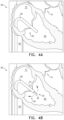
FIGS. 13-14 are schematic illustrations showing leaflet supports implanted at the tricuspid valve, in accordance with some applications of the present invention;
FIGS. 15A-C are schematic illustrations showing different perspective views of a leaflet support, in accordance with some applications of the present invention;
FIGS. 16-17 are schematic illustrations showing the leaflet support implanted at the tricuspid valve, in accordance with some applications of the present invention;
FIGS. 18A-C are schematic illustrations showing different perspective views of a leaflet support, in accordance with some applications of the present invention;
FIG. 19 includes schematic illustrations showing the leaflet support implanted at the tricuspid valve, in accordance with some applications of the present invention;
FIGS. 20A-C are schematic illustrations showing different perspective views of a leaflet support, in accordance with some applications of the present invention; and
FIG. 21 includes schematic illustrations showing the leaflet support implanted at the tricuspid valve, in accordance with some applications of the present invention.
DETAILED DESCRIPTION OF EMBODIMENTS
Reference is made to FIGS. 1A-C, which are schematic illustrations showing perspective views of a leaflet support 20, in accordance with some applications of the invention.
As shown, leaflet support 20 comprises a ring-shaped frame 30 that defines an array of adjoining cells 32. The ring formed by frame 30 extends radially outward from an aperture 34 that is defined by an inner ring-perimeter 26, to an outer ring-perimeter 28. For some applications, aperture 34 is central with respect to leaflet support 20 (e.g., with respect to outer ring-perimeter 28 of frame 30). That is, for such applications, a central axis d18 of leaflet support 20 passes through aperture 34 (e.g., through a center point d35 of the aperture).
For some applications, an annulus-fitting zone 33 of leaflet support 20 is concavely shaped. For example, and as shown in FIG. 1C, annulus-fitting zone 33 may be shaped as a spherical segment. Alternatively or in addition, annulus-fitting zone 33 may be frustoconical.
Typically, each cell 32, and therefore frame 30 as a whole, is configured to facilitate passage of blood therethrough, such that when leaflet support 20 is implanted within a heart 90 of a subject, blood may flow between an upstream side 22 and a downstream side 24 of the frame.
For some applications, and as shown, each cell 32 is defined by frame 30, without other elements within the cell. It is hypothesized by the inventors that cells 32 being defined solely by the frame: (i) facilitates passage of blood through the cells, and (ii) reduces the amount of material required to define the cells.
For some applications, and as shown, adjoining cells 32 form a series of geometric patterns. For some such applications, and as shown, the series of geometric patterns is repeated circumferentially about frame 30. It is hypothesized by the inventors that cells 32 forming a repeating series of geometric patterns: (i) facilitates distribution of external forces applied to frame 30, among the cells, and (ii) increases likelihood that different portions of frame 30 will react similarly to the application of external forces.
Leaflet support 20 further comprises a barrier 36 that is impermeable to blood flow. For some applications, and as shown, barrier 36 is a flexible sheet. For example, barrier 36 may comprise a sheet (e.g., a fabric and/or a polymer, such as a polymer fabric). Alternatively, barrier 36 may comprise an ex-vivo-derived or in-vitro-derived tissue, such as pericardium. Barrier 36 is coupled (e.g., fixedly coupled, such as by stitching or by gluing) to frame 30 such that the barrier obstructs blood flow through aperture 34.
For some applications, barrier 36 is planar (e.g., disc-shaped). For example, and as shown in FIGS. 1A-1B, barrier 36 may be shaped as a circular disc. Alternatively, barrier 36 may be shaped as an oval disc. Alternatively still, barrier 36 may be shaped as a “D”-shaped disc.
For some applications, and as shown, barrier 36 is centrally located with respect to leaflet support 20. That is, central axis d18 of the support passes through barrier 36. For some such applications, and as shown, central axis d18 passes through a center point d37 of barrier 36.
For some applications, and as shown, aperture 34 is centrally located with respect to leaflet support 20. That is, central axis d18 of the support passes through aperture 34. For some such applications, and as shown, central axis d18 passes through a center point d35 of aperture 34. For example, central axis d18 may pass through both center point d35 of aperture 34, as well as center point d37 of barrier 36.
Typically, barrier 36 and aperture 34 at least partially overlap, e.g., such that barrier 36 covers at least 10 percent (e.g., at least 20 percent, e.g., at least 30 percent, e.g., at least 40 percent, e.g., at least 50 percent, e.g., at least 60 percent, e.g., at least 70 percent, e.g., at least 80 percent, e.g., at least 90 percent) and/or up to 100 percent (e.g., up to 90 percent, e.g., up to 80 percent, e.g., up to 70 percent, e.g., up to 60 percent, e.g., up to 50 percent, e.g., up to 40 percent, e.g., up to 30 percent, e.g., up to 20 percent) of the cross-sectional area of the aperture. For example, barrier 36 may cover the aperture entirely. For some applications, barrier 36 covers an area greater than aperture area. For example, barrier 36 may be larger than the aperture, and/or may extend radially outward further than an inner ring-perimeter 26, e.g., such that the barrier covers at least some of frame 30 (e.g., covering at least a portion of at least one of the cells defined by the frame).
For some applications, and as shown, barrier 36 does not cover cells 32 of frame 30, e.g., such that barrier 36 is disposed only radially inward from inner ring-perimeter 26. For example, and as shown in the inset of FIG. 1B, barrier 36 may be coupled to frame 30 via fasteners 38.
Leaflet support 20 further comprises a plurality of ventricular legs 40 (e.g., three legs, as shown). For some applications, each ventricular leg 40 is coupled to frame 30 (e.g., at inner ring-perimeter 26). For some such applications, ventricular legs 40 and barrier 36 are each coupled to the frame at a shared site of frame 30.
For some applications and as shown, legs 40 are connected to frame 30 via a connecting portion 44 disposed downstream of aperture 34. Typically for such applications, connecting portion 44 also connects each leg 40 to the other legs. For some applications, and as shown in FIG. 1B, connecting portion 44 and barrier 36 are each coupled to frame 30 at a shared site of the frame (e.g., at inner ring-perimeter 26).
For some applications, and as shown, legs 40 are spaced evenly from central axis d18. That is, legs 40 are positioned to be radially equidistant from central axis d18.
For some applications, and as shown, legs 40 are arranged evenly about central axis d18. For some applications, radial arrangement of legs 40 around central axis d18 is determined responsively to anatomy of a given native valve (e.g., a tricuspid valve 60 or a mitral valve 74) at which support 20 is to be implanted. For some such applications, two legs 40 may be disposed radially closer to each other than they are to a third leg. For example, legs 40 may be arranged such that two legs may be positioned under a posterior leaflet 63 of mitral valve 74, and the third leg may be positioned under an anterior leaflet 61 of the mitral valve. Alternatively, legs 40 may be arranged such that each respective leg may be positioned under an anterior leaflet, posterior leaflet or a septal leaflet of tricuspid valve 60.
Typically, each leg 40 extends (e.g., from connecting portion 44) both radially outward, and upstream toward frame 30. For some applications, and as shown, end-portions 41 of legs 40 do not reach frame 30. Typically for such applications, each respective end-portion 41 faces frame 30 (e.g., from a position that is (i) radially outward of barrier 36 and/or inner ring-perimeter 26; and (ii) downstream of frame 30.
Reference is made to FIG. 2 , which includes schematic illustrations showing leaflet support 20 in an expanded state, and in a compressed state suitable for transluminal delivery, in accordance with some applications of the invention.
For some applications, leaflet support 20 (e.g., frame 30 and/or legs 40 thereof) comprises an elastic shape-memory material (e.g., Nitinol), such that upon removal of external constraining forces, leaflet support 20 automatically expands into the expanded state. As shown in upper frame of FIG. 2 , while support 20 is in the expanded state, the ring formed by frame 30 typically extends radially outward (e.g., from connecting portion 44).
For some applications, and as shown, while leaflet support 20 is in the compressed state (lower frame of FIG. 2 ), ventricular legs 40 extend downstream from connecting portion 44, and/or frame 30 assumes a tubular shape extending upstream from the connecting portion. For example, cells 32 may become narrower as frame 30 assumes the tubular shape. For some such applications, boundaries of at least some of cells 32 may come into contact with each other as frame 30 assumes the tubular shape.
For some applications in which frame 30 assumes a tubular shape while leaflet support 20 is compressed into the compressed state, frame 30 assumes the tubular shape around barrier 36, such that the barrier is disposed within a lumen defined by the tubular shape.
Reference is made to FIG. 3 , which is a schematic illustration showing system 10 comprising leaflet support 20 and delivery tool 80, in accordance with some applications of the invention. As shown, FIG. 3 shows leaflet support 20, in the compressed state, disposed within delivery tool 80 for transluminal (e.g., transfemoral) delivery to heart 90.
Reference is made to FIGS. 4A-F, which are schematic illustrations showing leaflet support 20 being implanted at tricuspid valve 60 of heart 90, in accordance with some applications of the invention. Particularly, leaflet support 20 is shown expanding into the expanded state as it is exposed from delivery tool 80.
Illustrating implantation of leaflet support 20 at tricuspid valve 60 is not meant to exclude implantation of leaflet support 20 at other native valves (e.g., a mitral valve 74) of heart 90, mutatis mutandis.
FIG. 4A shows delivery tool 80 having been advanced via inferior vena cava 66, through right atrium 70 to right ventricle 68. As shown in FIG. 4B, delivery tool 80 has begun to be retracted over leaflet support 20 such that end-portions 41 of ventricular legs 40 are exposed from the tool. FIG. 4C shows delivery tool 80 having been further retracted over leaflet support 20, such that ventricular legs 40 are further exposed from the tool. As described hereinabove, shape-memory of ventricular legs 40 causes the legs to extend radially outward.
Accordingly, FIG. 4D shows ventricular legs 40 having extended further radially outward, as delivery tool 80 is further retracted, exposing connecting portion 44. Since a frame 30 is still disposed within tool 80, connecting portion 44 typically remains at least compressed, as the frame is exposed from the tool (FIG. 4E). As shown in FIG. 4F, leaflet support 20 is deployed such that frame 30 is disposed upstream of annulus 48 of tricuspid valve 60. As shown, frame 30 (e.g., annulus-fitting zone 33 thereof) is placed against annulus 48 such that tissue of the annulus supports leaflet support 20. For some applications, and as shown, while frame 30 is supported by tissue of annulus 48, ventricular legs 40 contact valvular tissue on the ventricular side of tricuspid valve 60.
Reference is made to FIG. 5 , which includes schematic illustrations showing leaflet support 20 implanted at tricuspid valve 60, in accordance with some applications of the invention. The left pane of FIG. 5 shows tricuspid valve 60 during ventricular systole, and the right pane of FIG. 5 shows the tricuspid valve during ventricular diastole.
As shown, leaflet support 20 is typically sized such that frame 30 fits annulus 48 of tricuspid valve 60 (e.g., such that frame 30 (e.g., annulus-fitting zone 33 thereof) can be placed against the annulus). For example, a greatest width (e.g., a greatest diameter) of the ring formed by frame 30 (measured transverse to a central axis d18 of support 20) may be greater than 20 mm (e.g., greater than 30 mm, e.g., greater than 40 mm, e.g., greater than 50 mm, e.g., greater than 60 mm, e.g., greater than 70 mm, e.g., greater than 80 mm, e.g., greater than 90 mm) and/or less than 100 mm (e.g., less than 90 mm, e.g., less than 80 mm, e.g., less than 70 mm, e.g., less than 60 mm, e.g., less than 50 mm, e.g., less than 40 mm, e.g., less than 30 mm). Further, a greatest width of support 20 as a whole (measured transverse to axis d18) may be greater than 20 mm (e.g., greater than 30 mm, e.g., greater than 40 mm, e.g., greater than 50 mm, e.g., greater than 60 mm, e.g., greater than 70 mm, e.g., greater than 80 mm, e.g., greater than 90 mm) and/or less than 100 mm (e.g., less than 90 mm, e.g., less than 80 mm, e.g., less than 70 mm, e.g., less than 60 mm, e.g., less than 50 mm, e.g., less than 40 mm, e.g., less than 30 mm).
It is hypothesized by the inventors that implantation of leaflet support 20 at tricuspid valve 60 may facilitate treatment of different pathological processes effecting heart 90. For example, in some cases, one or more of the native leaflets may translate or “flail” from right ventricle 68 into right atrium 70 (e.g., during ventricular systole). It is hypothesized by the inventors that upon implantation of leaflet support 20 at the native valve, barrier 36 and/or frame 30 may be disposed such that they obstruct flailing of the native leaflets. In some cases, the subject may experience retrograde blood flow, or “regurgitation” from a ventricle to an atrium of the heart (e.g., during ventricular systole). It is therefore further hypothesized by the inventors that upon implantation of leaflet support 20 at the native valve, barrier 36 obstruct regurgitation.
The right pane of FIG. 5 shows the native leaflets having deflected downstream as heart 90 cycles from ventricular systole to ventricular diastole. As shown, leaflet support 20 typically affords the native leaflets a range of motion in which to deflect during the cardiac cycle. Arrows indicate antegrade blood flow from right atrium 70 on upstream side 22 of support 20 to right ventricle 68 on downstream side 24 of the ring. Since barrier 36 typically obstructs blood flow through aperture 34, arrows indicate flow of blood via cells 32, radially outward of the barrier.
Reference is made to FIGS. 6A-B, which are schematic illustrations showing a leaflet support 20′, in accordance with some applications of the invention.
As shown, leaflet support 20′ is generally similar to leaflet support 20. Accordingly, components bearing identical reference numerals are typically interchangeable between leaflet support 20′ and leaflet support 20.
Leaflet support 20′ comprises a ring-shaped frame 30′ that defines an array of adjoining cells 32′. Frame 30′ is typically similar to frame 30, except where noted. Leaflet support 20′ further comprises a barrier 36′ that is impermeable to blood flow. Barrier 36′ is typically similar to barrier 36, except where noted.
One difference between leaflet support 20′ and leaflet support 20 lies in that barrier 36′ is offset with respect to frame 30′ (e.g., with respect to an outer ring-perimeter 28′ of the frame). That is, a central axis d18′ of support 20′ does not pass through a center point d37′ of barrier 36′. For some applications, and as shown in FIG. 6A, central axis d18′ nonetheless passes through barrier 36′.
For some applications, and as shown, barrier 36 covers a portion of frame 30 (e.g., at least a portion of at least one cell 32′), such that the barrier obstructs blood flow through the portion of the frame. For some such applications, and as shown, barrier 36′ is coupled to frame 30′ via a plurality of ring struts 31′ that extend from at least some of cells 32′. In this way, barrier 36′ is disposed off-center with respect to frame 30′. Alternatively or in addition, the shape or number of cells 32′ defining frame 30′ may be altered, relative to frame 30, thereby facilitating coupling barrier 36′ off of center with respect to frame 30′.
It is hypothesized by the inventors that the offset barrier 36′ of leaflet support 20′ may advantageously fit certain native valves (e.g., mitral valve 74, as shown). That is, in some cases, a site of leaflet flailing and/or regurgitation may be offset with respect to annulus 48 of the native valve. Therefore, in some such cases, offset leaflet support 20′ may be advantageously implanted at the native valve, such that barrier 36′ will be favorably positioned to block the flailing and/or regurgitation. For example, it may be desirable for two legs 40′ to be disposed radially closer to each other than they are to a third leg, as described hereinabove in reference to FIGS. 1A-C, in order to facilitate positioning barrier 36 favorably for blocking the flailing and/or regurgitation.
FIG. 6 showing support 20′ implanted at mitral valve 74 is not intended to exclude cases in which non-offset leaflet support 20 may be advantageously implanted at mitral valve 74, or wherein offset leaflet support 20′ may be advantageously implanted at tricuspid valve 60.
Reference is made to FIGS. 7A-F, which are schematic illustrations showing use of a system 110 comprising a barrier-delivery tool 150 and a leaflet support 120, in accordance with some applications of the invention.
As shown, leaflet support 120 is generally similar to leaflet support 20′. Accordingly, components bearing identical reference numerals are typically interchangeable between leaflet support 120 and leaflet support 20′.
For some applications, and as shown, a barrier-delivery tool 150 may be used to couple a barrier 136 to frame 130 of support 120. For some such applications, and as shown in FIG. 7A, delivery tool 150 is also used to deploy frame 130 of support 120 at the native valve. For example, and as shown, delivery tool 150 may reversibly connect to a portion of frame 130. It is hypothesized by the inventors that delivery tool 150 being reversibly connected to frame 130 facilitates use of the delivery tool to couple barrier 136 to the frame, as described hereinbelow.
A difference between supports 120 and 20′ is that while support 20′ is typically provided with barrier 36′ already coupled to frame 30′, for some applications and as shown in FIG. 7A, frame 130 is deployed at the heart prior to coupling barrier 136 to the frame. Typically for such applications, barrier 136 is transluminally advanced to the heart before the barrier is coupled to frame 130. That is, barrier 136 may be coupled to frame 130 during deployment of the leaflet support 120.
For some applications, and as shown, barrier 136 is transluminally coupled to frame 130 after the frame is implanted at the native valve (e.g., while the frame remains disposed at the native valve).
FIG. 7B shows barrier 136 being deployed from a barrier-delivery capsule 154 of barrier-delivery tool 150. For some applications, and as shown in the inset of FIG. 7C, barrier 136 comprises a flexible sheet (e.g., a fabric sheet) 138 that is coupled to a barrier-frame 135. For example, and as shown, barrier-frame 135 may be ring-shaped. Alternatively or in addition, barrier-frame 135 may be shaped to define cells, and/or radially-aligned elements. For some such applications, barrier-frame 135 comprises a shape-memory material. For some such applications, barrier 136 is constrained within barrier-delivery capsule 154 to a compressed width (e.g., a compressed diameter), and exposure of the barrier from capsule 154 causes the barrier to expand to an expanded width (e.g., an expanded diameter). In this way, expansion of the barrier to the expanded width typically causes sheet 138 to cover barrier-frame 135 such that the sheet obstructs blood flow through the barrier-frame.
FIG. 7C shows barrier 136 having been deployed from barrier-delivery capsule 154, at an intermediate step in which barrier 136 is still engaged by delivery tool 150. During this intermediate step, extracorporeal control of delivery tool 150 regulates both: (i) longitudinal movement of barrier 136 along a central axis d116 of barrier-delivery tool 150, and (ii) rotation of the barrier about the central axis. In this way, delivery tool 150 facilitates alignment of barrier 136 to a desired portion of frame 130.
FIG. 7D shows barrier 136 having been rotated about central axis d116 of delivery tool 150. For some applications, and as shown, barrier 136 is offset with respect to tool 150. That is, central axis d116 of tool 150 does not pass through a center-point d137 of barrier 136.
For some applications, and as shown, barrier 136 comprises a frame-fitting portion 152 that is dimensioned to fit (e.g., to snugly engage) a portion of frame 130. For some applications, barrier 136 is offset with respect to frame-fitting portion 152 thereof. That is, frame-fitting portion 152 is defined at a portion of barrier 136 that is radially outward of center-point d137. In this way, and as shown, rotation of barrier 136 about frame-fitting portion 152 positions a greater portion of the barrier on a particular side of the frame-fitting portion.
For some applications, and as shown, central axis d116 and a central axis d118 of support 120 are coaxial, such that rotation of barrier 136 using delivery tool 150 also rotates the barrier with respect to frame 130. In this way, rotation of barrier 136 may be used to align the barrier with a desired portion of frame 130, prior to coupling the barrier to the frame, which is hypothesized by the inventors to facilitate alignment of the barrier with a desired anatomical location (a location identified with leaflet flailing and/or regurgitation) of the native valve.
As shown in FIGS. 7D-E, barrier 136 is typically coupled to frame 130, after the barrier is radially aligned to the desired portion of the barrier, e.g., by fitting frame-fitting portion 152 to frame 130. For some applications, and similarly to barrier 36′, barrier 136 is offset with respect to frame 130. Typically, and as shown in FIG. 7F, after barrier 136 is coupled to frame 130, the barrier is decoupled from delivery tool 150. Delivery tool 150 is removed from the subject, such that fully assembled support 120 remains at the native valve.
Reference is made to FIGS. 8A-C, which are schematic illustrations showing a system 210 comprising a leaflet support 220 and an adjustment tool 250, in accordance with some applications of the invention.
As shown, leaflet support 220 is generally similar to leaflet support 20. Accordingly, components bearing identical reference numerals are typically interchangeable between leaflet support 220 and leaflet support 20.
Leaflet support 220 comprises a ring-shaped frame 230 that defines an array of adjoining cells 232, and that is typically similar to frame 30, except where noted. Leaflet support 220 further comprises a barrier 236 (e.g., comprising a flexible sheet) that is impermeable to blood flow.
A difference between supports 20 and 220 is that whereas barrier 36 is typically fixedly coupled to frame 30, barrier 236 is adjustably coupled to frame 230 (e.g., to one or more sizing struts 231 thereof). Typically, and as shown, barrier 236 is transluminally adjustable in a manner that adjusts a portion of an area of aperture 234 (an “aperture area”) that is covered by the barrier. For example, the portion of the aperture area covered by barrier 236 may be repositioned and/or resized.
For some applications, and as shown, an adjustment tool 250 may be used to transluminally adjust the portion of the aperture area covered by barrier 236. For some such applications, adjustment tool 250 also facilitates implantation of support 220 at the native valve (e.g., may be a component of a delivery tool).
For some applications, barrier 236 comprises one or more adjustment locks 264 configured to facilitate engagement of the barrier by tool 250. FIG. 8A shows support 220 having been implanted at the native valve, and adjustment tool 250 engaging adjustment locks 264 of barrier 236. For some applications, and as shown, each end-portion 262 of a respective arm 260 of adjustment tool 250, engages an adjustment lock 264 of barrier 236.
For some applications, adjustment tool 250 is extracorporeally controlled to transfer a force to barrier 236 (e.g., to adjustment locks 264 thereof) in order to change the portion of the aperture area covered by the barrier. As shown in FIG. 8B, the force has caused adjustment lock 264 to move along sizing strut 231, radially away from center-point d237 of barrier 236 and toward outer ring-perimeter 228.
In response to radial movement of adjustment lock 264, barrier 236 may stretch and/or move, thereby adjusting the portion of the aperture area covered by the barrier. For some applications, barrier 236 comprises an elastic material. Therefore, for some such applications, radial movement of adjustment lock 264 stretches barrier 236 such that a greater portion of the aperture area becomes covered by the barrier. Alternatively, barrier 236 may comprise a nonelastic material that is incapable of stretching in response to radial movement of adjustment lock 264. Therefore, for some such applications, radial movement of one of the adjustment locks 264 causes movement of barrier 236 (e.g., such that the entire barrier moves radially). Alternatively still, barrier 236 may comprise a slightly elastic material, such that radial movement of adjustment lock 264 both stretches and causes movement of the barrier.
It is generally desirable that the change in the portion of the aperture area covered by barrier 236 remain in effect, after adjustment tool 250 has been disengaged and removed. Therefore, support 220 typically comprises a locking mechanism to retain barrier 236 in its adjusted configuration. For example, and as shown, frame 230 may comprise sizing struts 231 (inset of FIG. 8A). For some such applications, sizing struts 231 are shaped to define angled protrusions 235 along a length of the sizing struts. For example, the protrusions may be shaped such that a greater force is required to move adjustment lock 264 radially outward along sizing strut 231, than is required to move the lock radially inward along the sizing strut. In this way, adjustment lock 264 may be anticipated to remain in the radial position to which the lock was advanced by adjustment tool 250, also after disengagement of the tool from the lock. As such, the portion of the aperture area covered by barrier 236 while tool 250 engages the barrier may be anticipated to be maintained, after disengagement of the tool from the barrier.
FIG. 8C shows adjustment tool 250 having been transluminally withdrawn, such that the position of adjustment lock 264, as well as the portion of the aperture area covered by barrier 236, remains generally similar to that shown in FIG. 8B.
In FIGS. 8A-C, barrier 236 is shown as being generally triangular in shape (e.g., a circular triangle, such as a Reuleaux triangle or a deltoid curve). While it is hypothesized by the inventors that such a triangular shape may facilitate stretching barrier 236 towards one or more corners of the barrier (e.g., for use with an adjustment tool 250 that comprises three arms 260), other shapes of the barrier, and corresponding configurations of adjustment tool 250, mutatis mutandis, are contemplated.
Reference is made to FIG. 9 , which is a schematic illustration showing a leaflet support 320, in accordance with some applications of the invention.
As shown, leaflet support 320 is generally similar to leaflet support 20. Accordingly, components bearing identical reference numerals are typically interchangeable between leaflet support 320 and leaflet support 20.
Leaflet support 320 comprises a ring-shaped frame 330 that defines an array of adjoining cells 332. Similarly to frame 30, frame 330 extends radially outward from an aperture 334 that is defined by an inner ring-perimeter 326, to an outer ring-perimeter 328.
Further similarly to leaflet support 20, support 320 comprises a blood flow-impermeable barrier 336 that is coupled to frame 330 such that the barrier obstructs blood flow through aperture 334. However, a difference between supports 20 and 320 is that support 320 comprises a plurality of barriers 336 (e.g., two barriers, such as 336 a and 336 b shown in FIG. 9 , or more). For some applications, each of barriers 336 obstructs blood flow not only through aperture 334, but also through a portion of frame 330. However, barriers 336 are typically spaced apart from each other to allow blood flow between the respective barriers and through frame 330.
For some applications, barriers 336 are offset with respect to frame 330. That is, a central axis d318 does not pass through respective center-points d337 a or d337 b of barriers 336 a, 336 b. For some such applications, and as shown, central axis d318 does not pass through any portion of barriers 336 a, 336 b.
For some applications, support 320 is provided with barriers 336 fixedly coupled to frame 330—i.e., the position of the barriers is predetermined. Alternatively, the position of one or more of barriers 336 may be adjusted (e.g., relative to aperture 334 and frame 330), e.g., according to the judgement of a clinician. For example, the respective positions of barriers 336 may be adjusted prior to delivery of support 320 to the heart, and/or after fastening frame 330 to the native valve (e.g., transluminally, as described hereinabove in reference to FIGS. 8A-B).
Reference is made to FIGS. 10A-C, which are schematic illustrations showing perspective views of a leaflet support 420, a leaflet support 520 and a leaflet support 620, in accordance with some applications of the invention.
Certain aspects of leaflet supports 420, 520, 620 are shared with previously described leaflet support 20. Thus, components that are identically named between supports 420, 520, 620 and support 20 share similar features and serve similar functions as each other. Similarly to support 20, supports 420, 520, 620 comprise a frame 430, 530, 630 that defines an aperture 434, 534, 634, as well as ventricular legs 440, 540, 640 and a barrier 436, 536, 636. Similarly to frame 30 of leaflet support 20 described hereinabove, frame 430, 530, 630 defines an array of adjoining cells 432, 532, 632 that form a ring that extends radially outward from an inner ring-perimeter 426, 526, 626 to an outer ring-perimeter 428, 528, 628. Further similarly to frame 30 of support 20, frame 430, 530, 630 is configured to facilitate blood flow between an upstream side 422, 522, 622 and a downstream side 424, 524, 624 of respective rings formed by each support 420, 520, 620.
Further similarly to barrier 36 of leaflet support 20, barrier 436, 536, 636 of support 420, 520, 620 obstructs blood flow through aperture 434, 534, 634. However, in contrast to leaflet support 20, leaflet support 420, 520, 620 comprises a tubular portion 442, 542, 642 that supports the barrier. As shown, tubular portion 442, 542, 642 comprises a circumferential wall 446, 546, 646 that extends between an upstream end 445 and a downstream end 447 of the tubular portion.
For some applications, a circumferential space 448, 548, 648 (e.g., that circumscribes circumferential wall 446, 546, 646) is defined between tubular portion 442, 542, 642 and legs 440, 540, 640. Typically for such applications, circumferential space 448, 548, 648 is both: (i) radially inward from legs 440, 540, 640, and (ii) downstream of a downstream side 424, 524, 624 of frame 430, 530, 630. In this way, circumferential space 448, 548, 648 is typically free of elements that would obstruct movement of leaflets of the native valve. It is hypothesized by the inventors that circumferential space 448, 548, 648 facilitates functioning of the native valve while leaflet support 420, 520, 620 is implanted at that valve, by allowing leaflets of the native valve to deflect as heart 90 cycles between ventricular systole and ventricular diastole.
Typically for applications in which the leaflet support comprises a tubular portion, the tubular portion is positioned and sized to facilitate obstruction of blood flow through aperture, as described hereinbelow.
For some applications, and as shown, tubular portion 442, 542, 642 is coupled to frame 430, 530, 630 downstream of aperture 434, 534, 634 (e.g., the tubular portion is connected to inner ring-perimeter 426, 526, 626).
For some applications, tubular portion 442, 542, 642 and aperture 434, 534, 634 are of similar width (e.g., such that a tubular area is no less than 80 percent of an aperture area, and up to 120 percent of the aperture area). For some such applications, the tubular area is equal to the aperture area.
For some applications, and as shown in FIG. 10A, tubular portion 442, 542, 642 is radially centered with respect to frame 430, 530, 630. That is, circumferential wall 446, 546, 646 circumscribes central axis d418, d518, d618 of leaflet support 20.
For some applications, leaflet support 420, 520, 620 is configured to obstruct blood flow not just through aperture 434, 534, 634 but also through tubular portion 442, 542, 642.
For some such applications, and as shown, a circumferential sleeve 449, 549, 649 is coupled to (e.g., covers) circumferential wall 446, 546, 646. Circumferential sleeve 449, 549, 649 is typically impermeable to blood flow (e.g., the sleeve may comprise the same material as the barrier). It is hypothesized by the inventors that implanting support 420, 520, 620 at the native valve may advantageously mitigate regurgitation by circumferential sleeve 449 acting as a spacer against which the native leaflets may coapt against during ventricular systole.
For some such applications, and as shown regarding support 420, barrier 436 (e.g., barrier 436 a and barrier 436 b) covers both upstream end 445 (FIG. 10B) and downstream end 447 (FIG. 10C) of tubular portion 442.
Reference is made to FIGS. 11-12 , which are schematic illustrations showing perspective views of leaflet supports 520, 620, in accordance with some applications of the invention.
As shown, and in contrast to support 420, supports 520 and 620 each have an open end, not covered by respective barrier 536, 636. That is, tubular portion 542 of support 520 has an open upstream end (FIG. 11 ), while barrier 536 covers downstream end 547 (FIG. 10C). Complementarily, tubular portion 642 of support 620 has an open downstream end (FIG. 12 ), while barrier 636 covers upstream end 645 (FIG. 10B).
When considering supports 420, 520, 620 in relation to support 20, tubular portion 442, 542, 642 may be considered to serve as a connecting portion (e.g., similar to connecting portion 44, mutatis mutandis). That is, tubular portion 442, 542, 642 couples ventricular legs 440, 540, 640 to frame 430, 530, 630, while also coupling the legs to each other.
Therefore, another difference between supports 420, 520, 620 and support 20 lies in the respective point from which each leg 440, 540, 640 extends radially outward and upstream, toward frame 430, 530, 630. That is, for some applications, each leg 440, 540, 640 extends outward and upstream from tubular portion 442, 542, 642. For some such applications, each leg 440, 540, 640 extends further outward than barrier 436, 536, 636 and/or inner ring-perimeter 426, 526, 626.
In other respects, supports 420, 520, 620 are similar to support 20 described hereinabove. For some applications, and similarly to central axis d48 of support 20, central axis d418, d518, d618 passes through barrier 436, 536, 636 (e.g., such that the central axis passes through a center point of the barrier). Alternatively or in addition, central axis d418, d518, d618 may pass through aperture 434, 534, 634 (e.g., such that central axis d418 passes through a center point of the aperture).
Supports 420, 520, 620 are typically sized to fit annulus 48 of the native valve. For example, a greatest width (e.g., a greatest diameter) of the ring formed by frame 430, 530, 630 (measured transverse to a central axis d418, d518, d618 of support 420, 520, 620) may be greater than 20 mm (e.g., greater than 30 mm, e.g., greater than 40 mm, e.g., greater than 50 mm, e.g., greater than 60 mm, e.g., greater than 70 mm, e.g., greater than 80 mm, e.g., greater than 90 mm) and/or less than 100 mm (e.g., less than 90 mm, e.g., less than 80 mm, e.g., less than 70 mm, e.g., less than 60 mm, e.g., less than 50 mm, e.g., less than 40 mm, e.g., less than 30 mm). Further, a greatest width of support 420, 520, 620 as a whole (measured transverse to axis d418, d518, d618) may be greater than 20 mm (e.g., greater than 30 mm, e.g., greater than 40 mm, e.g., greater than 50 mm, e.g., greater than 60 mm, e.g., greater than 70 mm, e.g., greater than 80 mm, e.g., greater than 90 mm) and/or less than 100 mm (e.g., less than 90 mm, e.g., less than 80 mm, e.g., less than 70 mm, e.g., less than 60 mm, e.g., less than 50 mm, e.g., less than 40 mm, e.g., less than 30 mm). For some applications, and similarly to annulus-fitting zone 33, an annulus-fitting zone 433, 533, 633 of leaflet support 20 is concavely shaped (e.g., frustoconical shaped or shaped as a spherical segment).
Reference is made to FIGS. 13-14 , which are schematic illustrations showing leaflet support 420, 520, 620 implanted at tricuspid valve 60, in accordance with some applications of the invention.
As shown in FIG. 13 , support 420, 520, 620 is deployed such that frame 430, 530, 630 is disposed upstream of annulus 48 of tricuspid valve 60. As shown, frame 430, 530, 630 (e.g., annulus-fitting zone 433, 533, 633 thereof) is placed against annulus 48 such that tissue of the annulus supports leaflet support 420, 520, 620. For some applications, and as shown, while frame 430, 530, 630 is supported by tissue of annulus 48, ventricular legs 440, 540, 640 contact valvular tissue on the ventricular side of tricuspid valve 60.
The left pane of FIG. 14 shows tricuspid valve 60 during ventricular systole, and the right pane of FIG. 14 shows the tricuspid valve during ventricular diastole. It is hypothesized by the inventors that implantation of leaflet support 20 at tricuspid valve 60 may facilitate treatment of different pathological processes effecting heart 90. For example, in some cases, one or more of the native leaflets may flail or blood may regurgitate from right ventricle 68 into right atrium 70 (e.g., during ventricular systole). It is hypothesized by the inventors that upon implantation of support 420, 520, 620 at the native valve, barrier 436, 536, 636 and/or frame 430, 530, 630 may obstruct flailing and/or regurgitation.
The right pane of FIG. 14 shows the native leaflets having deflected downstream as heart 90 cycles from ventricular systole to ventricular diastole. As shown, support 420, 520, 620 typically affords the native leaflets a range of motion in which to deflect during the cardiac cycle. Arrows indicate antegrade blood flow from right atrium 70 on upstream side 422, 522, 622 of the ring, via cells 432, 532, 632.
Reference is made to FIGS. 15A-C, which are schematic illustrations showing different perspective views of a leaflet support 720, in accordance with some applications of the invention.
As shown, leaflet support 720 is in many ways similar to leaflet support 20. Accordingly, components that are identically named between leaflet support 720 and previously described leaflet support 20 typically share similar features and serve similar functions as each other. That is, leaflet support 720 comprises a blood-impermeable barrier 736 that is coupled to a frame 730 in a manner that obstructs blood flow through an aperture 734, between an upstream side 722 and a downstream side 724 of the frame.
Further similarly to as described hereinabove with reference to FIG. 16 regarding connecting portion 44 of support 20, connecting portion 744 of leaflet support 720 connects each of a plurality of ventricular legs 740 to frame 730, such that each leg extends radially outward from the connecting portion, and upstream toward the frame. However, legs 740 of support 720 may extend further upstream than do legs 40 of support 20. For example, shape-memory of legs 740 of support 720 may be such that each leg end-portion 741 reaches (e.g., presses against) frame 730 and/or barrier 736. For some applications, leg end-portion 741 extends upstream of at least a portion of frame 730, e.g., pressing against barrier 736 such that the barrier bulges away from upstream side 722.
Another difference between leaflet support 720 and leaflet support 20 lies in the radial position of leg end- portions 41, 741 with respect to barrier 36, 736. As shown in FIGS. 1A-B, leg end-portions 41 typically extend radially outward of barrier 36. However, for some applications, and as shown, barrier 736 and legs 740 extend outward to approximately the same extent (e.g., to exactly the same extent). For some such applications, barrier 736 extends further outward than do legs 740. For some such applications, legs 740 extend further outward than does barrier 736.
Reference is made to FIGS. 16-17 , which are schematic illustrations showing leaflet support 720 implanted at tricuspid valve 60, in accordance with some applications of the invention.
As shown in FIG. 16 , support 720 is deployed such that frame 730 is disposed upstream of annulus 48 of tricuspid valve 60. Similarly to frame 30 of support 20 described hereinabove, frame 730 is placed against tissue of right atrium 70 of heart 90. However, in contrast to frame 30, frame 730 does not comprise an annulus-fitting zone. In further contrast to frame 30, frame 730 is typically sized to not reach annulus 48 when implanted at the native valve. For such applications, a greatest width (e.g., a greatest diameter) of the ring formed by frame 730 (measured transverse to a central axis d718 of support 720) is less than the greatest width of frames 30, 30′, 130, 230, 330, 430, 530, 630. For example, the greatest width of the ring may be greater than 10 mm (e.g., greater than 20 mm, e.g., greater than 30 mm, e.g., greater than 40 mm, e.g., greater than 50 mm) and/or less than 60 mm (e.g., less than 50 mm, e.g., less than 40 mm, e.g., less than 30 mm, e.g., less than 20 mm). Further, a greatest width of support 720 as a whole (measured transverse to axis d718) may be greater than 10 mm (e.g., greater than 20 mm, e.g., greater than 30 mm, e.g., greater than 40 mm, e.g., greater than 50 mm, e.g., greater than 60 mm, e.g., greater than 70 mm, e.g., greater than 80 mm, e.g., greater than 90 mm) and/or less than 100 mm (e.g., less than 90 mm, e.g., less than 80 mm, e.g., less than 70 mm, e.g., less than 60 mm, e.g., less than 50 mm, e.g., less than 40 mm, e.g., less than 30 mm, e.g., less than 20 mm).
In further contrast to support 20, support 720 is shown such that cusps of native leaflets 61, 63 are captured between frame 730 and legs 740. That is, leg end-portions 741 abut leaflets 61, 63 at a greater distance from frame 730 than were they disposed prior to implantation (FIGS. 15A-C). In this way, shape-memory of legs 740 may cause tissue of the native valve (e.g., cusps of native leaflets 61, 63) to be squeezed between the legs and frame 730. It is hypothesized by the inventors that squeezing tissue of the native valve between legs 740 and frame 730 facilitates fastening support 720 to the native valve.
Support 720 being fastened to the native valve by squeezing tissue between legs 740 and frame 730 stands in contrast to the manner in which supports 20, 420, 520, 620 are fastened to the native valve. That is, instead of squeezing tissue of the native valve, supports 20, 420, 520, 620 are typically implanted such that frame 30, 430, 530, 630 abuts annulus 48. Since frame 30, 430, 530, 630 (e.g., annulus-fitting zone 33, 433, 533, 633 thereof) is typically sized to fit annulus 48 of the native valve, it is hypothesized by the inventors that abutment of the frame to the annulus may be sufficient to inhibit downstream migration of supports 20, 420, 520, 620. Similarly, legs 40, 440, 540, 640 of supports 20, 420, 520, 620 have a span that is sufficient to inhibit upstream migration of the supports. Supports 20, 420, 520, 620 therefore typically do not require immobilization or gripping of leaflets, and are therefore typically not configured to do so.
The left pane of FIG. 17 shows tricuspid valve 60 during ventricular systole, and the right pane of FIG. 17 shows the tricuspid valve during ventricular diastole. It is hypothesized by the inventors that implantation of leaflet support 720 at tricuspid valve 60 may facilitate treatment of different pathological processes effecting heart 90. For example, in some cases, one or more of the native leaflets may flail or blood may regurgitate from right ventricle 68 into right atrium 70 (e.g., during ventricular systole). Similarly to support 20, it is hypothesized by the inventors that upon implantation of support 720 at the native valve, barrier 736 and/or frame 730 may obstruct flailing and/or regurgitation.
Supports 20, 420, 520, and 620 are hypothesized by the inventors to reduce valve regurgitation by inhibiting the native leaflets from flailing into the atrium during ventricular systole, while allowing the leaflets to deflect into the ventricle during ventricular diastole, e.g., as they would in the absence of the support. In contrast, support 720 is hypothesized by the inventors to reduce valve regurgitation by restraining the edges of the leaflets close to each other, so as to configure the leaflets into a multi-orifice arrangement. Therefore, support 720 is configured to squeeze the native leaflets between legs 740 and frame 730 of support 720 in order to grip the leaflets, while supports 20, 420, 520, and 620 are typically not configured in this manner. The right-side frame of FIG. 17 shows a portion of the native leaflets having deflected downstream during ventricular diastole, to a lesser degree than as shown in the right pane of FIG. 5 .
As described hereinabove, support 720 is configured to configure the leaflets into a multi-orifice arrangement. That is, a secondary aperture 765 (e.g., three secondary apertures 765 a, 765 b, 765 c for a trileaflet valve such as the tricuspid valve, or two secondary apertures for a bileaflet valve, such as the mitral valve) typically open between the native leaflets, radially outward from frame 730, as heart 90 cycles from ventricular systole to ventricular diastole. Arrows indicate antegrade blood flow from right atrium 70 to right ventricle 68, through secondary apertures 765 a, 765 b, 765 c. It is hypothesized by the inventors that, for some applications, the smaller size of frame 730 compared with that of frames 30, 430, 530, 630 may further facilitate antegrade blood flow through secondary apertures 765.
Reference is made to FIGS. 18A-C and 20A-C, which are schematic illustrations showing perspective views of respective leaflet supports 820, 920, in accordance with some applications of the invention.
As shown, leaflet supports 820, 920 are each in certain ways similar to leaflet support 20 described hereinabove. Components that are identically named between the leaflet supports typically share similar features and serve similar functions as each other. As such, leaflet supports 820 and 920 will first be jointly described in relation to leaflet support 20, after which differences between leaflet supports 820 and 920 will be described.
Similarly to leaflet support 20, each of leaflet supports 820, 920 comprises a frame 830, 930 that defines an array of adjoining cells 832, 932 and an aperture 834, 934 between an upstream side 822, 922 and a downstream side 824, 924 of the frame. Similarly to frame 30, which extends radially inward from an outer ring-perimeter 28, frames 830, 930 extend radially inward from outer frame-perimeter 828, 928 (FIGS. 18A, 20A).
However, in contrast to frame 30 of leaflet support 20, frames 830, 930 are not necessarily ring-shaped. Therefore, whereas frame 30 extends radially outward from inner ring-perimeter 26 that defines aperture 34, frames 830, 930 each comprise a plurality of aperture-surrounding struts 844, 944 that extend radially inwardly and in a downstream direction from outer frame-perimeter 828 (FIGS. 18B-C and 20B-C).
For some applications, and as shown in FIGS. 18B and 20B, two aperture-surrounding struts (e.g., 844 a and 844 b, 944 a and 944 b) surround each aperture 834, 934. For some such applications, frame 830, 930 defines a plurality of apertures (834 i, 834 ii, 834 iii, or 934 i, 934 ii, 934 iii), such that each aperture is surrounded by at least two aperture-surrounding struts (FIGS. 18A, 20A).
Further similarly to leaflet support 20, leaflet supports 820 and 920 comprise ventricular legs 840, 940 that extend radially outward and upstream, towards frame 830, 930 (FIGS. 18C and 20C). Ventricular legs 840, 940 typically afford the native leaflets a range of motion in which to deflect during the cardiac cycle, as described hereinbelow with reference to FIGS. 19 and 21 .
Similarly to the application described hereinabove with reference to FIGS. 1A-5 , in which legs 40 are connected to frame 30 via connecting portion 44, legs 840, 940 are typically connected to frame 830, 930 via aperture-surrounding struts 844, 944. For some applications, and as shown, each ventricular leg 840, 940 extends radially outward, and toward frame 830, 930 from a downstream end 845, 945 of aperture-surrounding strut 844, 944. For example, each leg 840, 940 may extend radially outward from a pair of the aperture-surrounding struts 844, 944 (e.g., such that the pair of aperture-surrounding struts meet at downstream end 845, 945). For some such applications, each of the pair of aperture-surrounding struts partially surrounds a different aperture 834, 934 (FIGS. 18B-C and 20B-C).
Further similarly to leaflet support 20, leaflet supports 820 and 920 respectively comprise a barrier 836, 936 that is impermeable to blood flow. Barrier 836, 936 is coupled to frame 830, 930 in a manner that obstructs blood flow through aperture 834, 934 (e.g., by at least partially covering at least one of apertures 834 i, 834 ii, 834 iii or 934 i, 934 ii, 934 iii). For example, and as shown in FIGS. 18A and 20A, barrier 836, 936 is coupled to frame 830, 930 in a manner that partially covers more than one of apertures 834, 934.
For some applications, and further similarly to leaflet support 20, barrier 836, 936 is coupled to frame 830, 930 in a manner that also at least partially covers the array of cells 832, 932 (not shown). For example, and as shown, barrier 836, 936 may be coupled to frame 830, 930 in a manner that at least partially covers a plurality of cells 832, 932 (e.g., each cell of frame 830, 930).
A feature that distinguishes between leaflet supports 820 and 920 lies in the shape of respective barriers 836, 936. Barrier 836 of leaflet support 820 is in many ways similar to barrier 36 of leaflet support 20. For example, barrier 836 may define a barrier-fitting portion as described hereinabove with reference to barrier 36 of leaflet support 20, mutatis mutandis.
In contrast to barrier 836, barrier 936 defines a radial strip 938 that extends between central axis d918 and outer frame-perimeter 928. That is, radial strip 938 may not reach central axis d918 and/or outer frame-perimeter 928, yet the radial strip extends between the central axis and the outer frame-perimeter. In this way, radial strip 938 extends radially inwardly toward central axis d918 and radially outwardly toward the outer frame-perimeter. For some applications, radial strip 938 may be sized to correspond to dimensions of the native heart valve. For example, radial strip 938 may extend at least two thirds of a radial distance from central axis d918 to outer frame-perimeter 928.
For some applications, barrier 936 defines more than one radial strip 938 (e.g., corresponding to a number of commissures of a native heart valve). For some such applications, each radial strip 938 is positioned to align with a respective commissure of the native heart valve. For example, and as shown, a leaflet support that is configured to be implanted at tricuspid valve 60 may have exactly three radial strips 938.
Reference is made to FIGS. 19 and 21 , which include schematic illustrations showing leaflet supports 820, 920 respectively implanted at tricuspid valve 60, in accordance with some applications of the invention. The left panes of FIGS. 19 and 21 show tricuspid valve 60 during ventricular systole, and the right panes of FIGS. 19 and 21 show the tricuspid valve during ventricular diastole.
Similarly to as described hereinabove with reference to leaflet support 20, each cell 832, 932 and therefore frame 830, 930 as a whole, is configured to facilitate passage of blood therethrough. Therefore, when leaflet support 820, 920 is implanted at tricuspid valve 60, blood may flow between upstream side 822, 922 and downstream side 824, 924 of the frame (e.g., during ventricular diastole).
Further similarly to leaflet support 20, leaflet supports 820 and 920 are typically sized such that frame 830, 930 fits annulus 48 of tricuspid valve 60 (e.g., such that frame 830, 930 (e.g., an annulus-fitting zone 833, 933 thereof) can be placed against the annulus). A greatest width (measured transverse to axis d818, d918) of frame 830, 930 is also typically similar to the greatest width of frame 30. For some applications, the greatest width of frame 830, 930 is between 10 mm and 100 mm. For some such applications, the greatest width of frame 830, 930 is less than 60 mm. Alternatively or additionally, the greatest width of frame 830, 930 may be greater than 40 mm.
Further similarly to leaflet support 20, upon implantation of leaflet support 820, 920 at the native valve, barrier 836, 936 and/or frame 830, 930 are typically disposed such that they reduce flailing of native leaflets of the heart into an atrium of the heart, and barrier 836, 936 may obstruct regurgitation of blood (e.g., during ventricular systole). Thus, leaflet support 820, 920 may be desirably implanted in the heart of a subject experiencing leaflet flailing and/or regurgitation at a portion of a native heart valve that is covered by barrier 836, 936 when the leaflet support is implanted at the native valve.
Furthermore, barrier 836, 936 is typically sized and positioned to facilitate antegrade blood flow during ventricular diastole. Arrows in the right panes of FIGS. 19 and 21 indicate antegrade blood flow from the right atrium on upstream side 22 of support 820, 920 to the right ventricle on downstream side 824, 924 of frame 830, 930.
For some applications, and as shown in FIG. 19 , barrier 836 of leaflet support 820 only partially covers apertures 834. As such, blood may flow antegrade through apertures 834 and/or cells 832 of leaflet support 820, during ventricular diastole.
In contrast to barrier 836, radial strips 938 of leaflet support 920 extend radially outwardly toward outer frame-perimeter 928. Thus, leaflet support 920 may be desirably implanted in the heart of a subject experiencing leaflet flailing and/or regurgitation at a portion of a native heart valve that is covered by radial strips 938 when leaflet support 920 is implanted at the native valve. It is nonetheless desirable that radial strips 938 do not unduly obstruct antegrade blood flow during ventricular diastole. Radial strips 938 are therefore typically sized and positioned so as to allow for blood to flow between the radial strips (right pane of FIG. 21 ).
It will be appreciated by persons skilled in the art that the present invention is not limited to what has been particularly shown and described hereinabove. Rather, the scope of the present invention includes both combinations and subcombinations of the various features described hereinabove, as well as variations and modifications thereof that are not in the prior art, which would occur to persons skilled in the art upon reading the foregoing description.

Claims (30)

The invention claimed is:
1. Apparatus for use with a native valve of a heart of a subject, the apparatus comprising a leaflet support, the leaflet support comprising:
a frame having an upstream side and a downstream side, the frame:
defining an array of adjoining cells, and an aperture between the upstream side and the downstream side, and
configured to:
be placed against an annulus of the heart, and
facilitate blood flow, via the cells of the array of adjoining cells,
between the upstream side and the downstream side;
a barrier:
made of material that is impermeable to blood flow, and
coupled to the frame in a manner that obstructs blood flow through the aperture; and
a plurality of ventricular legs, each ventricular leg extending radially outward and upstream, toward the frame,
wherein the leaflet support is shaped to define a central longitudinal axis that is configured to pass through the material of the barrier throughout the cardiac cycle.
2. The apparatus according to claim 1, wherein each of the ventricular legs is coupled to the frame.
3. The apparatus according to claim 1, wherein each ventricular leg extends further radially outward than the barrier.
4. The apparatus according to claim 1, wherein the aperture is a first aperture, and the frame further defines a second aperture between the upstream side and the downstream side.
5. The apparatus according to claim 1, wherein:
the aperture is a first aperture,
the frame is shaped to define a second aperture between the upstream side and the downstream side, and
the frame comprises a plurality of aperture-surrounding struts, at least two of the aperture-surrounding struts surrounding the first aperture and at least two of the aperture-surrounding struts surrounding the second aperture, the aperture-surrounding struts extending radially inwardly and in a downstream direction from an outer frame-perimeter of the frame.
6. The apparatus according to claim 5, wherein each ventricular leg extends radially outward from exactly two of the aperture-surrounding struts.
7. The apparatus according to claim 5, wherein each ventricular leg extends radially outward from a downstream end of at least one of the aperture-surrounding struts.
8. The apparatus according to claim 7, wherein each ventricular leg extends, from the downstream end of at least one of the aperture-surrounding struts:
radially outward, and
toward the frame.
9. The apparatus according to claim 7, wherein a respective end-portion of each ventricular leg faces the frame from a position that is:
radially outward of the barrier, and
downstream from the frame.
10. The apparatus according to claim 7, wherein, in an absence of tissue between the ventricular legs and the frame, a respective end-portion of each ventricular leg is disposed upstream from the frame.
11. The apparatus according to claim 7, wherein, in an absence of tissue between the ventricular legs and the barrier, a respective end-portion of each ventricular leg presses against the barrier.
12. The apparatus according to claim 1, wherein the barrier is coupled to the frame in a manner that at least partially covers at least one of the cells.
13. The apparatus according to claim 12, wherein the barrier is coupled to the frame in a manner that at least partially covers each cell of the frame.
14. The apparatus according to claim 1, wherein:
the frame defines an outer frame-perimeter, and
the barrier is shaped to define at least one radial strip, the at least one radial strip extending radially inwardly toward a central axis of the leaflet support and radially outwardly toward the outer frame-perimeter.
15. The apparatus according to claim 14, wherein the at least one radial strip extends at least two thirds of a radial distance from the central axis to the outer frame-perimeter.
16. The apparatus according to claim 14, wherein the at least one radial strip is a plurality of the radial strips.
17. The apparatus according to claim 16, wherein the plurality of the radial strips comprises exactly three of the radial strips.
18. The apparatus according to claim 16, wherein the plurality of the radial strips are positioned to each align with a respective commissure of the native valve of the heart of the subject and to reduce flailing of native leaflets of the heart into an atrium of the heart.
19. The apparatus according to claim 1, wherein:
the aperture defines an aperture area, and
the barrier obstructs blood flow through the aperture by covering a portion of the aperture area.
20. The apparatus according to claim 1, further comprising a barrier-delivery tool, the barrier-delivery tool configured to:
reversibly engage the barrier, and
while the frame is disposed at the native valve, transluminally:
position the barrier with respect to the frame, and
couple the barrier to the frame in the manner that obstructs blood flow through the aperture.
21. The apparatus according to claim 1, wherein the barrier is circular or elliptical.
22. The apparatus according to claim 1, wherein the barrier is “D”-shaped.
23. The apparatus according to claim 1, wherein the adjoining cells of the array are arranged to shape the frame as a ring having an inner ring-perimeter that defines the aperture.
24. The apparatus according to claim 1, wherein the central longitudinal axis of the leaflet support passes through a center point of the barrier.
25. The apparatus according to claim 1, wherein the barrier is offset with respect to the central longitudinal axis of the leaflet support.
26. The apparatus according to claim 1, wherein the barrier has a transverse plane that is coplanar with a transverse plane of the aperture, and wherein the barrier covers at least a portion of the aperture.
27. The apparatus according to claim 1, wherein the leaflet support is configured to facilitate functioning of the native valve while the leaflet support is implanted at the native valve, by allowing leaflets of the native valve to deflect as the heart cycles between ventricular systole and ventricular diastole.
28. The apparatus according to claim 1, wherein the barrier is planar.
29. The apparatus according to claim 28, wherein the barrier is triangular.
30. The apparatus according to claim 28, wherein the barrier is shaped as a disc.
US17/337,893 2020-08-16 2021-06-03 Leaflet support Active 2041-10-23 US11857417B2 (en)

Priority Applications (2)

Application Number Priority Date Filing Date Title
US17/337,893 US11857417B2 (en) 2020-08-16 2021-06-03 Leaflet support
US18/512,654 US20240081997A1 (en) 2020-08-16 2023-11-17 Leaflet support

Applications Claiming Priority (2)

Application Number Priority Date Filing Date Title
US202063066268P 2020-08-16 2020-08-16
US17/337,893 US11857417B2 (en) 2020-08-16 2021-06-03 Leaflet support

Related Child Applications (1)

Application Number Title Priority Date Filing Date
US18/512,654 Continuation US20240081997A1 (en) 2020-08-16 2023-11-17 Leaflet support

Publications (2)

Publication Number Publication Date
US20220047388A1 US20220047388A1 (en) 2022-02-17
US11857417B2 true US11857417B2 (en) 2024-01-02

Family

ID=80224622

Family Applications (2)

Application Number Title Priority Date Filing Date
US17/337,893 Active 2041-10-23 US11857417B2 (en) 2020-08-16 2021-06-03 Leaflet support
US18/512,654 Pending US20240081997A1 (en) 2020-08-16 2023-11-17 Leaflet support

Family Applications After (1)

Application Number Title Priority Date Filing Date
US18/512,654 Pending US20240081997A1 (en) 2020-08-16 2023-11-17 Leaflet support

Country Status (1)

Country Link
US (2) US11857417B2 (en)

Citations (204)

* Cited by examiner, † Cited by third party
Publication number Priority date Publication date Assignee Title
US4423525A (en) 1981-07-14 1984-01-03 Sorin Biomedica S.P.A. Heart valve prosthesis
US4493329A (en) 1982-08-19 1985-01-15 Lynn Crawford Implantable electrode having different stiffening and curvature maintaining characteristics along its length
US4625727A (en) 1985-01-24 1986-12-02 Leiboff Arnold R Anastomosis device with excisable frame
US4778468A (en) 1980-09-25 1988-10-18 South African Invention Development Corporation Surgical implant
US4853986A (en) 1986-01-02 1989-08-08 The Awareness Marketing Corporation Water level control
WO1992005093A1 (en) 1990-09-25 1992-04-02 Allset Marine Lashing Ab A twist lock for joining corner boxes when loading containers
US5108420A (en) 1991-02-01 1992-04-28 Temple University Aperture occlusion device
US5330521A (en) 1992-06-29 1994-07-19 Cohen Donald M Low resistance implantable electrical leads
US5450860A (en) 1993-08-31 1995-09-19 W. L. Gore & Associates, Inc. Device for tissue repair and method for employing same
US5473812A (en) 1993-03-31 1995-12-12 Medtronic, Inc. Method of manufacturing medical electrical lead having a torque indicator
US5776178A (en) 1996-02-21 1998-07-07 Medtronic, Inc. Medical electrical lead with surface treatment for enhanced fixation
US5792400A (en) 1988-11-10 1998-08-11 Biocon Oy Method of manufacturing biodegradable surgical implants and devices
US5843120A (en) 1994-03-17 1998-12-01 Medinol Ltd. Flexible-expandable stent
US5957953A (en) 1996-02-16 1999-09-28 Smith & Nephew, Inc. Expandable suture anchor
US6027523A (en) 1997-10-06 2000-02-22 Arthrex, Inc. Suture anchor with attached disk
US6298272B1 (en) 1999-03-29 2001-10-02 Cardiac Pacemakers, Inc. High impedance electrode tip with internal drug delivery capability
US6299635B1 (en) 1997-09-29 2001-10-09 Cook Incorporated Radially expandable non-axially contracting surgical stent
US6332893B1 (en) 1997-12-17 2001-12-25 Myocor, Inc. Valve to myocardium tension members device and method
US20020032481A1 (en) 2000-09-12 2002-03-14 Shlomo Gabbay Heart valve prosthesis and sutureless implantation of a heart valve prosthesis
US20020151961A1 (en) 2000-01-31 2002-10-17 Lashinski Randall T. Medical system and method for remodeling an extravascular tissue structure
US20020177904A1 (en) 1999-12-22 2002-11-28 Huxel Shawn Thayer Removable stent for body lumens
US6575976B2 (en) 2000-06-12 2003-06-10 Arthrex, Inc. Expandable tissue anchor
US6613078B1 (en) 2000-08-02 2003-09-02 Hector Daniel Barone Multi-component endoluminal graft assembly, use thereof and method of implanting
US6613079B1 (en) 1998-02-05 2003-09-02 Medtronic, Inc. Radially-expandable stent with controllable force profile
US20030167071A1 (en) 2002-03-01 2003-09-04 Evalve, Inc. Suture fasteners and methods of use
US6616684B1 (en) 2000-10-06 2003-09-09 Myocor, Inc. Endovascular splinting devices and methods
US6626930B1 (en) 1999-10-21 2003-09-30 Edwards Lifesciences Corporation Minimally invasive mitral valve repair method and apparatus
US6626899B2 (en) 1999-06-25 2003-09-30 Nidus Medical, Llc Apparatus and methods for treating tissue
US6629921B1 (en) 1997-01-02 2003-10-07 Myocor, Inc. Heart wall tension reduction apparatus and method
US6641597B2 (en) 2001-05-25 2003-11-04 Arthrex, Inc. Interference fit knotless suture anchor fixation
US20030229350A1 (en) 1995-08-22 2003-12-11 Kay David B. Open helical organic tissue anchor having recessible head and method of making the organic tissue anchor
US20030236568A1 (en) 2002-05-10 2003-12-25 Hikmat Hojeibane Multi-lobed frame based unidirectional flow prosthetic implant
US20040024451A1 (en) 2002-01-02 2004-02-05 Medtronic, Inc. Prosthetic heart valve system
US6702846B2 (en) 1996-04-09 2004-03-09 Endocare, Inc. Urological stent therapy system and method
US6723038B1 (en) 2000-10-06 2004-04-20 Myocor, Inc. Methods and devices for improving mitral valve function
US6730118B2 (en) 2001-10-11 2004-05-04 Percutaneous Valve Technologies, Inc. Implantable prosthetic valve
US20040181287A1 (en) 2002-10-22 2004-09-16 Scimed Life Systems Male urethral stent device
US20040186566A1 (en) 2003-03-18 2004-09-23 Hindrichs Paul J. Body tissue remodeling methods and apparatus
US6797001B2 (en) 2002-03-11 2004-09-28 Cardiac Dimensions, Inc. Device, assembly and method for mitral valve repair
US20040193092A1 (en) 2003-03-26 2004-09-30 Scimed Life Systems, Inc. Self-retaining stent
US20040199183A1 (en) 1997-06-27 2004-10-07 Oz Mehmet C. Method and apparatus for circulatory valve repair
US20040236419A1 (en) 2001-12-21 2004-11-25 Simcha Milo Implantation system for annuloplasty rings
US20040260389A1 (en) 2003-04-24 2004-12-23 Cook Incorporated Artificial valve prosthesis with improved flow dynamics
US20050016560A1 (en) 2003-07-21 2005-01-27 Dee Voughlohn Unique hair-styling system and method
WO2005021063A2 (en) 2003-09-02 2005-03-10 3F Therapeutics, Inc. Medical device for reduction of pressure effects of cardiac tricuspid valve regurgitation
US6884250B2 (en) 2002-07-22 2005-04-26 Niti Medical Technologies Ltd. Intratubular anastomosis apparatus
US20050090827A1 (en) 2003-10-28 2005-04-28 Tewodros Gedebou Comprehensive tissue attachment system
US20050107812A1 (en) 2002-06-13 2005-05-19 Guided Delivery Systems, Inc. Delivery devices and methods for heart valve repair
US20050107871A1 (en) 2003-03-30 2005-05-19 Fidel Realyvasquez Apparatus and methods for valve repair
US6908478B2 (en) 2001-12-05 2005-06-21 Cardiac Dimensions, Inc. Anchor and pull mitral valve device and method
US20050177228A1 (en) 2003-12-16 2005-08-11 Solem Jan O. Device for changing the shape of the mitral annulus
US20050203606A1 (en) 2004-03-09 2005-09-15 Vancamp Daniel H. Stent system for preventing restenosis
US20050216039A1 (en) 2002-11-15 2005-09-29 Lederman Robert J Method and device for catheter based repair of cardiac valves
WO2005102194A2 (en) 2004-03-30 2005-11-03 Depuy Spine Sarl Double lead bone screw
US20050256532A1 (en) 2004-05-12 2005-11-17 Asha Nayak Cardiovascular defect patch device and method
US20060052821A1 (en) 2001-09-06 2006-03-09 Ovalis, Inc. Systems and methods for treating septal defects
US7041097B1 (en) 2000-12-21 2006-05-09 Cardiac Pacemakers, Inc. System and method for accessing the coronary sinus
US20060106423A1 (en) 2004-09-28 2006-05-18 Thomas Weisel Suture anchor
US20060129166A1 (en) 2004-12-15 2006-06-15 Vance Products Incorporated, D/B/A Cook Urological Incorporated Radiopaque manipulation devices
US20060161265A1 (en) 2002-12-02 2006-07-20 Levine Andy H Bariatric sleeve
US20060178700A1 (en) 2004-12-15 2006-08-10 Martin Quinn Medical device suitable for use in treatment of a valve
WO2006091163A1 (en) 2005-02-28 2006-08-31 Medtentia Ab Devices and a kit for improving the function of a heart valve
US7101395B2 (en) 2002-06-12 2006-09-05 Mitral Interventions, Inc. Method and apparatus for tissue connection
WO2006097931A2 (en) 2005-03-17 2006-09-21 Valtech Cardio, Ltd. Mitral valve treatment techniques
US20060229708A1 (en) 2005-02-07 2006-10-12 Powell Ferolyn T Methods, systems and devices for cardiac valve repair
US7125421B2 (en) 2001-08-31 2006-10-24 Mitral Interventions, Inc. Method and apparatus for valve repair
US20060241748A1 (en) 2005-03-25 2006-10-26 Lee Leonard Y Methods and apparatus for controlling the internal circumference of an anatomic orifice or lumen
US7144363B2 (en) 2001-10-16 2006-12-05 Extensia Medical, Inc. Systems for heart treatment
US20060282161A1 (en) 2003-06-20 2006-12-14 Medtronic Vascular, Inc. Valve annulus reduction system
US7159593B2 (en) 2003-04-17 2007-01-09 3F Therapeutics, Inc. Methods for reduction of pressure effects of cardiac tricuspid valve regurgitation
US20070016287A1 (en) 2005-03-25 2007-01-18 Cartledge Richard G Methods and apparatus for controlling the internal circumference of an anatomic orifice or lumen
US20070021781A1 (en) 2005-07-22 2007-01-25 Jervis James E Wedge Operated Retainer Device And Methods
US7169187B2 (en) 1999-12-22 2007-01-30 Ethicon, Inc. Biodegradable stent
US7175625B2 (en) 2002-11-25 2007-02-13 Triage Medical Soft tissue anchor and method of using same
US20070038293A1 (en) 1999-04-09 2007-02-15 St Goar Frederick G Device and methods for endoscopic annuloplasty
US20070038221A1 (en) 1999-10-26 2007-02-15 Stephen Fine Orthopaedic ligament fixation system
US20070049970A1 (en) 2005-09-01 2007-03-01 Ovalis Inc. Suture-based systems and methods for treating septal defects
US20070049942A1 (en) 2005-08-30 2007-03-01 Hindrichs Paul J Soft body tissue remodeling methods and apparatus
US20070061010A1 (en) 2005-09-09 2007-03-15 Hauser David L Device and method for reshaping mitral valve annulus
US20070066863A1 (en) 2005-08-31 2007-03-22 Medtronic Vascular, Inc. Device for treating mitral valve regurgitation
US7201772B2 (en) 2003-07-08 2007-04-10 Ventor Technologies, Ltd. Fluid flow prosthetic device
US20070093869A1 (en) 2003-06-20 2007-04-26 Medtronic Vascular, Inc. Device, system, and method for contracting tissue in a mammalian body
US20070118151A1 (en) 2005-11-21 2007-05-24 The Brigham And Women's Hospital, Inc. Percutaneous cardiac valve repair with adjustable artificial chordae
US20070162107A1 (en) 2003-12-23 2007-07-12 Sadra Medical, Inc. Methods and apparatus for endovascularly replacing a patient's heart valve
US20070198082A1 (en) 2005-12-15 2007-08-23 The Cleveland Clinic Foundation Apparatus and method for treating a regurgitant valve
US20070203391A1 (en) 2006-02-24 2007-08-30 Medtronic Vascular, Inc. System for Treating Mitral Valve Regurgitation
EP1836971A2 (en) 2006-03-21 2007-09-26 Ethicon Endo-Surgery, Inc. surgical fastener and instrument
US20070239265A1 (en) * 2006-04-06 2007-10-11 Medtronic Vascular, Inc. Catheter Delivered Valve Having a Barrier to Provide an Enhanced Seal
US20070250160A1 (en) 2006-04-21 2007-10-25 Medtronic Vascular, Inc. Device, system, and method for treating cardiac valve regurgitation
US20070276437A1 (en) 2006-05-25 2007-11-29 Mitralign, Inc. Lockers for surgical tensioning members and methods of using the same to secure surgical tensioning members
US20070282375A1 (en) 2006-05-03 2007-12-06 St. Jude Medical, Inc. Soft body tissue remodeling methods and apparatus
US7311728B2 (en) 1999-06-29 2007-12-25 Edwards Lifesciences Ag Device and method for treatment of mitral insufficiency
US20080003539A1 (en) 2004-03-05 2008-01-03 Dan Lundgren Tubular Bone Anchoring Element
US7316706B2 (en) 2003-06-20 2008-01-08 Medtronic Vascular, Inc. Tensioning device, system, and method for treating mitral valve regurgitation
US7316710B1 (en) 2002-12-30 2008-01-08 Advanced Cardiovascular Systems, Inc. Flexible stent
US20080035160A1 (en) 2006-06-21 2008-02-14 Woodson Beverly T System and method for temporary tongue suspension
US7338506B2 (en) 2001-09-05 2008-03-04 Caro Nicholas C Scleral clip and procedures for using same
US20080077231A1 (en) 2006-07-06 2008-03-27 Prescient Medical, Inc. Expandable vascular endoluminal prostheses
US7351256B2 (en) 2002-05-10 2008-04-01 Cordis Corporation Frame based unidirectional flow prosthetic implant
WO2008068756A2 (en) 2006-12-05 2008-06-12 Valtech Cardio, Ltd. Segmented ring placement
US7390329B2 (en) 2004-05-07 2008-06-24 Usgi Medical, Inc. Methods for grasping and cinching tissue anchors
US20080221672A1 (en) * 2007-02-23 2008-09-11 Endovalve, Inc. Mitral Valve System
US20080275469A1 (en) 2007-03-05 2008-11-06 Fanton Gary S Tack anchor systems, bone anchor systems, and methods of use
US20080288044A1 (en) 2005-10-31 2008-11-20 Osborne Thomas A Composite Stent Graft
US20080288062A1 (en) 2000-05-25 2008-11-20 Bioring Sa Device for shrinking or reinforcing the valvular orifices of the heart
US20080300629A1 (en) 2007-05-31 2008-12-04 Wilson-Cook Medical Inc. Suture lock
US20090084386A1 (en) 2007-10-01 2009-04-02 Mcclellan Annette M L Tubal ligation
US20090118776A1 (en) 2004-09-24 2009-05-07 Biomec, Inc. Tissue anchors
US7530995B2 (en) 2003-04-17 2009-05-12 3F Therapeutics, Inc. Device for reduction of pressure effects of cardiac tricuspid valve regurgitation
US7547321B2 (en) 2001-07-26 2009-06-16 Alveolus Inc. Removable stent and method of using the same
US7549983B2 (en) 1999-09-20 2009-06-23 Atritech, Inc. Method of closing an opening in a wall of the heart
WO2009080801A1 (en) 2007-12-21 2009-07-02 Medtentia Ltd Oy Cardiac valve downsizing device and method
US20090171439A1 (en) 2005-07-14 2009-07-02 Thomas Nissl Temporary Stent
WO2009101617A2 (en) 2008-02-11 2009-08-20 Corassist Cardiovascular Ltd. Ventricular function assisting devices and methods of use thereof
US20090216265A1 (en) 2002-08-29 2009-08-27 Scimed Life Systems, Inc. Tissue fasteners and related deployment systems and methods
US20090222081A1 (en) 2008-01-24 2009-09-03 Coherex Medical, Inc. Methods and apparatus for reducing valve prolapse
US20090254103A1 (en) 2006-03-29 2009-10-08 Deutsch Harvey L Method and device for cavity obliteration
US20090264995A1 (en) 2008-04-16 2009-10-22 Subramanian Valavanur A Transvalvular intraannular band for valve repair
US7628797B2 (en) 2006-01-31 2009-12-08 Edwards Lifesciences Corporation System, apparatus, and method for fastening tissue
US7632303B1 (en) 2000-06-07 2009-12-15 Advanced Cardiovascular Systems, Inc. Variable stiffness medical devices
US7635329B2 (en) 2004-09-27 2009-12-22 Evalve, Inc. Methods and devices for tissue grasping and assessment
US20090326648A1 (en) 2004-05-14 2009-12-31 Ample Medical, Inc. Devices, systems, and methods for reshaping a heart valve annulus, including the use of an adjustable bridge implant system
WO2010004546A1 (en) 2008-06-16 2010-01-14 Valtech Cardio, Ltd. Annuloplasty devices and methods of delivery therefor
US7666204B2 (en) 1999-04-09 2010-02-23 Evalve, Inc. Multi-catheter steerable guiding system and methods of use
US20100121349A1 (en) 2008-10-10 2010-05-13 Meier Stephen C Termination devices and related methods
US20100130992A1 (en) 2003-10-01 2010-05-27 Ample Medical, Inc. Devices, systems, and methods for reshaping a heart valve annulus, including the use of magnetic tools
US20100161047A1 (en) 2008-12-22 2010-06-24 Valtech Cardio, Ltd. Adjustable partial annuloplasty ring and mechanism therefor
US20100161041A1 (en) 2008-12-22 2010-06-24 Valtech Caridio, Ltd. Adjustable repair chords and spool mechanism therefor
WO2010071494A1 (en) 2008-12-19 2010-06-24 St.Jude Medical Ab A medical implantable lead and a method for ensuring proper and safe attachment of such a lead to an organ
US20100161042A1 (en) 2008-12-22 2010-06-24 Valtech Cardio,Ltd. Implantation of repair chords in the heart
US20100168791A1 (en) 2006-06-30 2010-07-01 Cvdevices, Llc (A California Limited Liability Company) Systems and methods for closing a hole in cardiac tissue
WO2010073246A2 (en) 2008-12-22 2010-07-01 Valtech Cardio, Ltd. Adjustable annuloplasty devices and adjustment mechanisms therefor
US20100174358A1 (en) 2001-12-03 2010-07-08 Rabkin Dmitry J Multi-Segment Modular Stent And Methods For Manufacturing Stents
US20100185278A1 (en) 2009-01-21 2010-07-22 Tendyne Medical Apical Papillary Msucle Attachment for Left Ventricular Reduction
US7771467B2 (en) 2006-11-03 2010-08-10 The Cleveland Clinic Foundation Apparatus for repairing the function of a native aortic valve
US20100204662A1 (en) 2007-06-04 2010-08-12 Mor Research Applications Ltd. Cardiac valve leaflet augmentation
US20100211166A1 (en) 2009-02-17 2010-08-19 Eran Miller Actively-engageable movement-restriction mechanism for use with an annuloplasty structure
US7780726B2 (en) 2001-07-04 2010-08-24 Medtronic, Inc. Assembly for placing a prosthetic valve in a duct in the body
US20100217382A1 (en) 2009-02-25 2010-08-26 Edwards Lifesciences Mitral valve replacement with atrial anchoring
US20100234935A1 (en) 2003-04-02 2010-09-16 Boston Scientific Scimed, Inc. Detachable And Retrievable Stent Assembly
US20100249908A1 (en) 2009-03-31 2010-09-30 Edwards Lifesciences Corporation Prosthetic heart valve system with positioning markers
US20100280604A1 (en) 2009-05-04 2010-11-04 Valtech Cardio, Ltd. Over-wire rotation tool
US20100286628A1 (en) 2009-05-07 2010-11-11 Rainbow Medical Ltd Gastric anchor
US20100286767A1 (en) 2009-05-07 2010-11-11 Valtech Cardio, Ltd. Annuloplasty ring with intra-ring anchoring
US20100324598A1 (en) 2002-11-26 2010-12-23 Abbott Laboratories Multi element biased suture clip
US7871433B2 (en) 2001-12-08 2011-01-18 Lattouf Omar M Treatments for a patient with congestive heart failure
US20110022164A1 (en) 2004-12-15 2011-01-27 Mednua Limited Medical device for use in treatment of a valve
US20110029066A1 (en) 2004-05-10 2011-02-03 Ran Gilad Stent valve and method of using same
US20110035000A1 (en) 2002-01-30 2011-02-10 Cardiac Dimensions, Inc. Tissue Shaping Device
US20110054519A1 (en) * 2008-03-26 2011-03-03 Malte Neuss Device for closing defects in the vascular system
US20110082538A1 (en) 2009-10-01 2011-04-07 Jonathan Dahlgren Medical device, kit and method for constricting tissue or a bodily orifice, for example, a mitral valve
US20110087146A1 (en) 2009-10-09 2011-04-14 Boston Scientific Scimed, Inc. Stomach bypass for the treatment of obesity
US20110093002A1 (en) 2009-10-20 2011-04-21 Wilson-Cook Medical Inc. Stent-within-stent arrangements
US20110106247A1 (en) 2009-10-29 2011-05-05 Valtech Cardio, Ltd. Tissue anchor for annuloplasty device
US20110106245A1 (en) 2009-10-29 2011-05-05 Valtech Cardio, Ltd. Apparatus for guide-wire based advancement of a rotation assembly
US20110112619A1 (en) 2009-11-12 2011-05-12 Foster Arthur J Helix fixation mechanism
US20110184510A1 (en) 2010-01-22 2011-07-28 4Tech, Sarl Tricuspid valve repair using tension
US7991484B1 (en) 2007-05-15 2011-08-02 Pacesetter, Inc. Active fixation medical lead and related method and system
US7993368B2 (en) 2003-03-13 2011-08-09 C.R. Bard, Inc. Suture clips, delivery devices and methods
US8010207B2 (en) 2002-10-31 2011-08-30 Medtronic, Inc. Implantable medical lead designs
US20110238112A1 (en) 2009-05-29 2011-09-29 Kim Andrew C Suture anchor
US20110238088A1 (en) 2001-11-28 2011-09-29 Aptus Endosystems, Inc. Devices, systems, and methods for supporting tissue and/or structures within a hollow body organ
US8029518B2 (en) 1999-04-09 2011-10-04 Evalve, Inc. Methods and devices for capturing and fixing leaflets in valve repair
US20110251678A1 (en) 2007-02-05 2011-10-13 Boston Scientific Scimed, Inc. Percutaneous Valve, System, and Method
US8043360B2 (en) 2006-11-07 2011-10-25 Dc Devices, Inc. Devices, systems and methods to treat heart failure
US20110264208A1 (en) 2010-04-27 2011-10-27 Medtronic, Inc. Prosthetic Heart Valve Devices and Methods of Valve Repair
US8052592B2 (en) 2005-09-27 2011-11-08 Evalve, Inc. Methods and devices for tissue grasping and assessment
WO2011143263A2 (en) 2010-05-10 2011-11-17 Heart Leaflet Technologies, Inc. Stentless support structure
US20120022633A1 (en) 2010-07-23 2012-01-26 Christopher Olson Retaining mechanisms for prosthetic valves
US20120022640A1 (en) 2010-07-21 2012-01-26 Yossi Gross Techniques for percutaneous mitral valve replacement and sealing
US8108054B2 (en) 2009-02-04 2012-01-31 Pacesetter, Inc. Active fixation implantable medical lead configured to indicate via fluoroscopy embedment of helical anchor in cardiac tissue
US20120035712A1 (en) 2010-01-22 2012-02-09 Francesco Maisano Method and apparatus for tricuspid valve repair using tension
US8142493B2 (en) 2003-12-23 2012-03-27 Mitralign, Inc. Method of heart valve repair
US8236013B2 (en) 2007-10-19 2012-08-07 Boston Scientific Scimed, Inc. Apparatus for placing medical implants
US20120215236A1 (en) 2010-06-22 2012-08-23 Olympus Medical Systems Corp. Tissue fastner production method and tissue fastener
US8262724B2 (en) 2008-04-18 2012-09-11 Medtronic Corevalve, Inc. Apparatus for treating a heart valve, in particular a mitral valve
US20120232373A1 (en) 2009-11-30 2012-09-13 St. Jude Medical Ab Medical implanatble lead with fixation detection
US8267981B2 (en) 2003-06-10 2012-09-18 Depuy Mitek, Inc. Suture anchor with improved drive head
WO2012127309A1 (en) 2011-03-21 2012-09-27 Ontorfano Matteo Disk-based valve apparatus and method for the treatment of valve dysfunction
US20120296349A1 (en) 2011-05-17 2012-11-22 Boston Scientific Scimed, Inc. Percutaneous Mitral Annulus Mini-Plication
US8323335B2 (en) 2008-06-20 2012-12-04 Edwards Lifesciences Corporation Retaining mechanisms for prosthetic valves and methods for using
US8332051B2 (en) 2004-12-03 2012-12-11 Medtronic, Inc. High impedance active fixation electrode of an electrical medical lead
US20130030522A1 (en) 2010-06-16 2013-01-31 Rowe Stanton J Devices and methods for heart treatments
US20130035759A1 (en) * 2011-08-05 2013-02-07 Yossi Gross Techniques for percutaneous mitral valve replacement and sealing
WO2013114214A2 (en) 2012-01-31 2013-08-08 Orford Holdings Sa Mitral valve docking devices, systems and methods
US20130325115A1 (en) 2012-05-31 2013-12-05 4Tech Inc. Locking concepts
US8628571B1 (en) 2012-11-13 2014-01-14 Mitraltech Ltd. Percutaneously-deliverable mechanical valve
WO2014150106A1 (en) * 2013-03-15 2014-09-25 Dc Devices, Inc. Devices and methods for retrievable intra-atrial implants
US20160030166A1 (en) 2011-07-27 2016-02-04 The Cleveland Clinic Foundation Apparatus, system, and method for treating a regurgitant heart valve
US20160199181A1 (en) * 2015-01-13 2016-07-14 George Kramer Implantable Transcatheter Intracardiac Devices and Methods for Treating Incompetent Atrioventricular Valves
US20160331523A1 (en) 2015-05-14 2016-11-17 Edwards Lifesciences Corporation Heart valve sealing devices and delivery devices therefor
US20170095331A1 (en) * 2014-05-16 2017-04-06 Netanel Benichou Replacement heart valve
US20170273789A1 (en) 2014-06-26 2017-09-28 Mitralix Ltd. Heart valve repair devices for placement in ventricle and delivery systems for implanting heart valve repair devices
US20180049874A1 (en) 2016-08-16 2018-02-22 Boston Scientific Scimed, Inc. Heart valve regurgitation anchor and delivery tool
WO2018050200A1 (en) 2016-09-16 2018-03-22 Coramaze Technologies Gmbh Heart implant
US20180243086A1 (en) 2017-02-24 2018-08-30 Abbott Cardiovascular Systems Inc. Double basket assembly for valve repair
WO2018178977A1 (en) 2017-03-27 2018-10-04 Vvital Biomed Ltd. Device and method for transcatheter mitral and tricuspid valve repair
US20180325661A1 (en) 2017-05-10 2018-11-15 Edwards Lifesciences Corporation Mitral valve spacer device
US20180353181A1 (en) 2017-06-07 2018-12-13 Evalve, Inc. Tissue compression device for cardiac valve repair
US20190053903A1 (en) 2017-08-17 2019-02-21 Boston Scientific Scimed, Inc. Anchor delivery system and methods for valve repair
US20190069991A1 (en) 2017-09-07 2019-03-07 Edwards Lifesciences Corporation Prosthetic spacer device for heart valve
US20190099267A1 (en) * 2016-03-22 2019-04-04 Mvalve Technologies Ltd. Replacement cardiac valve
US20200060849A1 (en) * 2018-08-21 2020-02-27 Boston Scientific Scimed, Inc. Projecting member with barb for cardiovascular devices
CN111067666A (en) * 2019-12-17 2020-04-28 宁波健世生物科技有限公司 Transcatheter valve replacement system

Patent Citations (226)

* Cited by examiner, † Cited by third party
Publication number Priority date Publication date Assignee Title
US4778468A (en) 1980-09-25 1988-10-18 South African Invention Development Corporation Surgical implant
US4423525A (en) 1981-07-14 1984-01-03 Sorin Biomedica S.P.A. Heart valve prosthesis
US4493329A (en) 1982-08-19 1985-01-15 Lynn Crawford Implantable electrode having different stiffening and curvature maintaining characteristics along its length
US4625727A (en) 1985-01-24 1986-12-02 Leiboff Arnold R Anastomosis device with excisable frame
US4853986A (en) 1986-01-02 1989-08-08 The Awareness Marketing Corporation Water level control
US5792400A (en) 1988-11-10 1998-08-11 Biocon Oy Method of manufacturing biodegradable surgical implants and devices
WO1992005093A1 (en) 1990-09-25 1992-04-02 Allset Marine Lashing Ab A twist lock for joining corner boxes when loading containers
US5108420A (en) 1991-02-01 1992-04-28 Temple University Aperture occlusion device
US5330521A (en) 1992-06-29 1994-07-19 Cohen Donald M Low resistance implantable electrical leads
US5473812A (en) 1993-03-31 1995-12-12 Medtronic, Inc. Method of manufacturing medical electrical lead having a torque indicator
US5450860A (en) 1993-08-31 1995-09-19 W. L. Gore & Associates, Inc. Device for tissue repair and method for employing same
US5843120A (en) 1994-03-17 1998-12-01 Medinol Ltd. Flexible-expandable stent
US20030229350A1 (en) 1995-08-22 2003-12-11 Kay David B. Open helical organic tissue anchor having recessible head and method of making the organic tissue anchor
US5957953A (en) 1996-02-16 1999-09-28 Smith & Nephew, Inc. Expandable suture anchor
US5776178A (en) 1996-02-21 1998-07-07 Medtronic, Inc. Medical electrical lead with surface treatment for enhanced fixation
US6702846B2 (en) 1996-04-09 2004-03-09 Endocare, Inc. Urological stent therapy system and method
US6629921B1 (en) 1997-01-02 2003-10-07 Myocor, Inc. Heart wall tension reduction apparatus and method
US20040199183A1 (en) 1997-06-27 2004-10-07 Oz Mehmet C. Method and apparatus for circulatory valve repair
US6299635B1 (en) 1997-09-29 2001-10-09 Cook Incorporated Radially expandable non-axially contracting surgical stent
US6027523A (en) 1997-10-06 2000-02-22 Arthrex, Inc. Suture anchor with attached disk
US6332893B1 (en) 1997-12-17 2001-12-25 Myocor, Inc. Valve to myocardium tension members device and method
US6613079B1 (en) 1998-02-05 2003-09-02 Medtronic, Inc. Radially-expandable stent with controllable force profile
US6298272B1 (en) 1999-03-29 2001-10-02 Cardiac Pacemakers, Inc. High impedance electrode tip with internal drug delivery capability
US7666204B2 (en) 1999-04-09 2010-02-23 Evalve, Inc. Multi-catheter steerable guiding system and methods of use
US20070038293A1 (en) 1999-04-09 2007-02-15 St Goar Frederick G Device and methods for endoscopic annuloplasty
US8029518B2 (en) 1999-04-09 2011-10-04 Evalve, Inc. Methods and devices for capturing and fixing leaflets in valve repair
US9044246B2 (en) 1999-04-09 2015-06-02 Abbott Vascular Inc. Methods and devices for capturing and fixing leaflets in valve repair
US6626899B2 (en) 1999-06-25 2003-09-30 Nidus Medical, Llc Apparatus and methods for treating tissue
US7186262B2 (en) 1999-06-25 2007-03-06 Vahid Saadat Apparatus and methods for treating tissue
US7311728B2 (en) 1999-06-29 2007-12-25 Edwards Lifesciences Ag Device and method for treatment of mitral insufficiency
US7549983B2 (en) 1999-09-20 2009-06-23 Atritech, Inc. Method of closing an opening in a wall of the heart
US6626930B1 (en) 1999-10-21 2003-09-30 Edwards Lifesciences Corporation Minimally invasive mitral valve repair method and apparatus
US20070038221A1 (en) 1999-10-26 2007-02-15 Stephen Fine Orthopaedic ligament fixation system
US20020177904A1 (en) 1999-12-22 2002-11-28 Huxel Shawn Thayer Removable stent for body lumens
US7169187B2 (en) 1999-12-22 2007-01-30 Ethicon, Inc. Biodegradable stent
US20020151961A1 (en) 2000-01-31 2002-10-17 Lashinski Randall T. Medical system and method for remodeling an extravascular tissue structure
US20080288062A1 (en) 2000-05-25 2008-11-20 Bioring Sa Device for shrinking or reinforcing the valvular orifices of the heart
US7632303B1 (en) 2000-06-07 2009-12-15 Advanced Cardiovascular Systems, Inc. Variable stiffness medical devices
US6575976B2 (en) 2000-06-12 2003-06-10 Arthrex, Inc. Expandable tissue anchor
US6613078B1 (en) 2000-08-02 2003-09-02 Hector Daniel Barone Multi-component endoluminal graft assembly, use thereof and method of implanting
US20020032481A1 (en) 2000-09-12 2002-03-14 Shlomo Gabbay Heart valve prosthesis and sutureless implantation of a heart valve prosthesis
US6616684B1 (en) 2000-10-06 2003-09-09 Myocor, Inc. Endovascular splinting devices and methods
US6723038B1 (en) 2000-10-06 2004-04-20 Myocor, Inc. Methods and devices for improving mitral valve function
US7041097B1 (en) 2000-12-21 2006-05-09 Cardiac Pacemakers, Inc. System and method for accessing the coronary sinus
US6641597B2 (en) 2001-05-25 2003-11-04 Arthrex, Inc. Interference fit knotless suture anchor fixation
US7780726B2 (en) 2001-07-04 2010-08-24 Medtronic, Inc. Assembly for placing a prosthetic valve in a duct in the body
US7547321B2 (en) 2001-07-26 2009-06-16 Alveolus Inc. Removable stent and method of using the same
US7125421B2 (en) 2001-08-31 2006-10-24 Mitral Interventions, Inc. Method and apparatus for valve repair
US7338506B2 (en) 2001-09-05 2008-03-04 Caro Nicholas C Scleral clip and procedures for using same
US20060052821A1 (en) 2001-09-06 2006-03-09 Ovalis, Inc. Systems and methods for treating septal defects
US6730118B2 (en) 2001-10-11 2004-05-04 Percutaneous Valve Technologies, Inc. Implantable prosthetic valve
US7144363B2 (en) 2001-10-16 2006-12-05 Extensia Medical, Inc. Systems for heart treatment
US20110238088A1 (en) 2001-11-28 2011-09-29 Aptus Endosystems, Inc. Devices, systems, and methods for supporting tissue and/or structures within a hollow body organ
US20100174358A1 (en) 2001-12-03 2010-07-08 Rabkin Dmitry J Multi-Segment Modular Stent And Methods For Manufacturing Stents
US6908478B2 (en) 2001-12-05 2005-06-21 Cardiac Dimensions, Inc. Anchor and pull mitral valve device and method
US7871433B2 (en) 2001-12-08 2011-01-18 Lattouf Omar M Treatments for a patient with congestive heart failure
US20040236419A1 (en) 2001-12-21 2004-11-25 Simcha Milo Implantation system for annuloplasty rings
US20040024451A1 (en) 2002-01-02 2004-02-05 Medtronic, Inc. Prosthetic heart valve system
US20110035000A1 (en) 2002-01-30 2011-02-10 Cardiac Dimensions, Inc. Tissue Shaping Device
US20030167071A1 (en) 2002-03-01 2003-09-04 Evalve, Inc. Suture fasteners and methods of use
US6797001B2 (en) 2002-03-11 2004-09-28 Cardiac Dimensions, Inc. Device, assembly and method for mitral valve repair
US7351256B2 (en) 2002-05-10 2008-04-01 Cordis Corporation Frame based unidirectional flow prosthetic implant
US20030236568A1 (en) 2002-05-10 2003-12-25 Hikmat Hojeibane Multi-lobed frame based unidirectional flow prosthetic implant
US7618449B2 (en) 2002-06-12 2009-11-17 Mitral Interventions Method and apparatus for tissue connection
US7101395B2 (en) 2002-06-12 2006-09-05 Mitral Interventions, Inc. Method and apparatus for tissue connection
US20050107812A1 (en) 2002-06-13 2005-05-19 Guided Delivery Systems, Inc. Delivery devices and methods for heart valve repair
US6884250B2 (en) 2002-07-22 2005-04-26 Niti Medical Technologies Ltd. Intratubular anastomosis apparatus
US20090216265A1 (en) 2002-08-29 2009-08-27 Scimed Life Systems, Inc. Tissue fasteners and related deployment systems and methods
US20040181287A1 (en) 2002-10-22 2004-09-16 Scimed Life Systems Male urethral stent device
US8010207B2 (en) 2002-10-31 2011-08-30 Medtronic, Inc. Implantable medical lead designs
US20050216039A1 (en) 2002-11-15 2005-09-29 Lederman Robert J Method and device for catheter based repair of cardiac valves
US7175625B2 (en) 2002-11-25 2007-02-13 Triage Medical Soft tissue anchor and method of using same
US20100324598A1 (en) 2002-11-26 2010-12-23 Abbott Laboratories Multi element biased suture clip
US20060161265A1 (en) 2002-12-02 2006-07-20 Levine Andy H Bariatric sleeve
US7316710B1 (en) 2002-12-30 2008-01-08 Advanced Cardiovascular Systems, Inc. Flexible stent
US7993368B2 (en) 2003-03-13 2011-08-09 C.R. Bard, Inc. Suture clips, delivery devices and methods
US20040186566A1 (en) 2003-03-18 2004-09-23 Hindrichs Paul J. Body tissue remodeling methods and apparatus
US20040193092A1 (en) 2003-03-26 2004-09-30 Scimed Life Systems, Inc. Self-retaining stent
US20050107871A1 (en) 2003-03-30 2005-05-19 Fidel Realyvasquez Apparatus and methods for valve repair
US20100234935A1 (en) 2003-04-02 2010-09-16 Boston Scientific Scimed, Inc. Detachable And Retrievable Stent Assembly
US7530995B2 (en) 2003-04-17 2009-05-12 3F Therapeutics, Inc. Device for reduction of pressure effects of cardiac tricuspid valve regurgitation
US7159593B2 (en) 2003-04-17 2007-01-09 3F Therapeutics, Inc. Methods for reduction of pressure effects of cardiac tricuspid valve regurgitation
US20040260389A1 (en) 2003-04-24 2004-12-23 Cook Incorporated Artificial valve prosthesis with improved flow dynamics
US8267981B2 (en) 2003-06-10 2012-09-18 Depuy Mitek, Inc. Suture anchor with improved drive head
US20070093869A1 (en) 2003-06-20 2007-04-26 Medtronic Vascular, Inc. Device, system, and method for contracting tissue in a mammalian body
US20060282161A1 (en) 2003-06-20 2006-12-14 Medtronic Vascular, Inc. Valve annulus reduction system
US7316706B2 (en) 2003-06-20 2008-01-08 Medtronic Vascular, Inc. Tensioning device, system, and method for treating mitral valve regurgitation
US7201772B2 (en) 2003-07-08 2007-04-10 Ventor Technologies, Ltd. Fluid flow prosthetic device
US20050016560A1 (en) 2003-07-21 2005-01-27 Dee Voughlohn Unique hair-styling system and method
WO2005021063A2 (en) 2003-09-02 2005-03-10 3F Therapeutics, Inc. Medical device for reduction of pressure effects of cardiac tricuspid valve regurgitation
US20100130992A1 (en) 2003-10-01 2010-05-27 Ample Medical, Inc. Devices, systems, and methods for reshaping a heart valve annulus, including the use of magnetic tools
US20050090827A1 (en) 2003-10-28 2005-04-28 Tewodros Gedebou Comprehensive tissue attachment system
US20050177228A1 (en) 2003-12-16 2005-08-11 Solem Jan O. Device for changing the shape of the mitral annulus
US8142493B2 (en) 2003-12-23 2012-03-27 Mitralign, Inc. Method of heart valve repair
US20070162107A1 (en) 2003-12-23 2007-07-12 Sadra Medical, Inc. Methods and apparatus for endovascularly replacing a patient's heart valve
US20080003539A1 (en) 2004-03-05 2008-01-03 Dan Lundgren Tubular Bone Anchoring Element
US20050203606A1 (en) 2004-03-09 2005-09-15 Vancamp Daniel H. Stent system for preventing restenosis
WO2005102194A2 (en) 2004-03-30 2005-11-03 Depuy Spine Sarl Double lead bone screw
US7390329B2 (en) 2004-05-07 2008-06-24 Usgi Medical, Inc. Methods for grasping and cinching tissue anchors
US20110029066A1 (en) 2004-05-10 2011-02-03 Ran Gilad Stent valve and method of using same
US20050256532A1 (en) 2004-05-12 2005-11-17 Asha Nayak Cardiovascular defect patch device and method
US20090326648A1 (en) 2004-05-14 2009-12-31 Ample Medical, Inc. Devices, systems, and methods for reshaping a heart valve annulus, including the use of an adjustable bridge implant system
US20090118776A1 (en) 2004-09-24 2009-05-07 Biomec, Inc. Tissue anchors
US7635329B2 (en) 2004-09-27 2009-12-22 Evalve, Inc. Methods and devices for tissue grasping and assessment
US20060106423A1 (en) 2004-09-28 2006-05-18 Thomas Weisel Suture anchor
US8332051B2 (en) 2004-12-03 2012-12-11 Medtronic, Inc. High impedance active fixation electrode of an electrical medical lead
US20060129166A1 (en) 2004-12-15 2006-06-15 Vance Products Incorporated, D/B/A Cook Urological Incorporated Radiopaque manipulation devices
US20060178700A1 (en) 2004-12-15 2006-08-10 Martin Quinn Medical device suitable for use in treatment of a valve
US20110022164A1 (en) 2004-12-15 2011-01-27 Mednua Limited Medical device for use in treatment of a valve
US20060229708A1 (en) 2005-02-07 2006-10-12 Powell Ferolyn T Methods, systems and devices for cardiac valve repair
WO2006091163A1 (en) 2005-02-28 2006-08-31 Medtentia Ab Devices and a kit for improving the function of a heart valve
WO2006097931A2 (en) 2005-03-17 2006-09-21 Valtech Cardio, Ltd. Mitral valve treatment techniques
US20090149872A1 (en) 2005-03-17 2009-06-11 Amir Gross Mitral valve treatment techniques
US20070016287A1 (en) 2005-03-25 2007-01-18 Cartledge Richard G Methods and apparatus for controlling the internal circumference of an anatomic orifice or lumen
US20060241748A1 (en) 2005-03-25 2006-10-26 Lee Leonard Y Methods and apparatus for controlling the internal circumference of an anatomic orifice or lumen
US20090171439A1 (en) 2005-07-14 2009-07-02 Thomas Nissl Temporary Stent
US20070021781A1 (en) 2005-07-22 2007-01-25 Jervis James E Wedge Operated Retainer Device And Methods
US20070049942A1 (en) 2005-08-30 2007-03-01 Hindrichs Paul J Soft body tissue remodeling methods and apparatus
EP1759663A2 (en) 2005-08-30 2007-03-07 St. Jude Medical, Inc. Soft body tissue remodeling methods and apparatus
US20070066863A1 (en) 2005-08-31 2007-03-22 Medtronic Vascular, Inc. Device for treating mitral valve regurgitation
US20070049970A1 (en) 2005-09-01 2007-03-01 Ovalis Inc. Suture-based systems and methods for treating septal defects
US20070061010A1 (en) 2005-09-09 2007-03-15 Hauser David L Device and method for reshaping mitral valve annulus
US7803187B2 (en) 2005-09-09 2010-09-28 Edwards Lifesciences Corporation Device and method for reshaping mitral valve annulus
US8052592B2 (en) 2005-09-27 2011-11-08 Evalve, Inc. Methods and devices for tissue grasping and assessment
US20080288044A1 (en) 2005-10-31 2008-11-20 Osborne Thomas A Composite Stent Graft
US20070118151A1 (en) 2005-11-21 2007-05-24 The Brigham And Women's Hospital, Inc. Percutaneous cardiac valve repair with adjustable artificial chordae
US20070198082A1 (en) 2005-12-15 2007-08-23 The Cleveland Clinic Foundation Apparatus and method for treating a regurgitant valve
US7628797B2 (en) 2006-01-31 2009-12-08 Edwards Lifesciences Corporation System, apparatus, and method for fastening tissue
US20070203391A1 (en) 2006-02-24 2007-08-30 Medtronic Vascular, Inc. System for Treating Mitral Valve Regurgitation
EP1836971A2 (en) 2006-03-21 2007-09-26 Ethicon Endo-Surgery, Inc. surgical fastener and instrument
US20090254103A1 (en) 2006-03-29 2009-10-08 Deutsch Harvey L Method and device for cavity obliteration
US20070239265A1 (en) * 2006-04-06 2007-10-11 Medtronic Vascular, Inc. Catheter Delivered Valve Having a Barrier to Provide an Enhanced Seal
US20070250160A1 (en) 2006-04-21 2007-10-25 Medtronic Vascular, Inc. Device, system, and method for treating cardiac valve regurgitation
US20070282375A1 (en) 2006-05-03 2007-12-06 St. Jude Medical, Inc. Soft body tissue remodeling methods and apparatus
US20070276437A1 (en) 2006-05-25 2007-11-29 Mitralign, Inc. Lockers for surgical tensioning members and methods of using the same to secure surgical tensioning members
US20080035160A1 (en) 2006-06-21 2008-02-14 Woodson Beverly T System and method for temporary tongue suspension
US20100168791A1 (en) 2006-06-30 2010-07-01 Cvdevices, Llc (A California Limited Liability Company) Systems and methods for closing a hole in cardiac tissue
US20080077231A1 (en) 2006-07-06 2008-03-27 Prescient Medical, Inc. Expandable vascular endoluminal prostheses
US7771467B2 (en) 2006-11-03 2010-08-10 The Cleveland Clinic Foundation Apparatus for repairing the function of a native aortic valve
US8043360B2 (en) 2006-11-07 2011-10-25 Dc Devices, Inc. Devices, systems and methods to treat heart failure
US9358371B2 (en) 2006-11-07 2016-06-07 Corvia Medical, Inc. Intra-atrial implants made of non-braided material
US7988725B2 (en) 2006-12-05 2011-08-02 Valtech Cardio, Ltd. Segmented ring placement
WO2008068756A2 (en) 2006-12-05 2008-06-12 Valtech Cardio, Ltd. Segmented ring placement
US20080262609A1 (en) 2006-12-05 2008-10-23 Valtech Cardio, Ltd. Segmented ring placement
US20090259307A1 (en) 2006-12-05 2009-10-15 Valtech Cardio, Ltd. Segmented ring placement
US20110251678A1 (en) 2007-02-05 2011-10-13 Boston Scientific Scimed, Inc. Percutaneous Valve, System, and Method
US20080221672A1 (en) * 2007-02-23 2008-09-11 Endovalve, Inc. Mitral Valve System
US20080275469A1 (en) 2007-03-05 2008-11-06 Fanton Gary S Tack anchor systems, bone anchor systems, and methods of use
US7991484B1 (en) 2007-05-15 2011-08-02 Pacesetter, Inc. Active fixation medical lead and related method and system
US20080300629A1 (en) 2007-05-31 2008-12-04 Wilson-Cook Medical Inc. Suture lock
US20100204662A1 (en) 2007-06-04 2010-08-12 Mor Research Applications Ltd. Cardiac valve leaflet augmentation
US20090084386A1 (en) 2007-10-01 2009-04-02 Mcclellan Annette M L Tubal ligation
US8236013B2 (en) 2007-10-19 2012-08-07 Boston Scientific Scimed, Inc. Apparatus for placing medical implants
WO2009080801A1 (en) 2007-12-21 2009-07-02 Medtentia Ltd Oy Cardiac valve downsizing device and method
US20090222081A1 (en) 2008-01-24 2009-09-03 Coherex Medical, Inc. Methods and apparatus for reducing valve prolapse
WO2009101617A2 (en) 2008-02-11 2009-08-20 Corassist Cardiovascular Ltd. Ventricular function assisting devices and methods of use thereof
US20110054519A1 (en) * 2008-03-26 2011-03-03 Malte Neuss Device for closing defects in the vascular system
US20090264995A1 (en) 2008-04-16 2009-10-22 Subramanian Valavanur A Transvalvular intraannular band for valve repair
US8262725B2 (en) 2008-04-16 2012-09-11 Cardiovascular Technologies, Llc Transvalvular intraannular band for valve repair
US8262724B2 (en) 2008-04-18 2012-09-11 Medtronic Corevalve, Inc. Apparatus for treating a heart valve, in particular a mitral valve
WO2010004546A1 (en) 2008-06-16 2010-01-14 Valtech Cardio, Ltd. Annuloplasty devices and methods of delivery therefor
US8323335B2 (en) 2008-06-20 2012-12-04 Edwards Lifesciences Corporation Retaining mechanisms for prosthetic valves and methods for using
US20100121349A1 (en) 2008-10-10 2010-05-13 Meier Stephen C Termination devices and related methods
WO2010071494A1 (en) 2008-12-19 2010-06-24 St.Jude Medical Ab A medical implantable lead and a method for ensuring proper and safe attachment of such a lead to an organ
US20100161041A1 (en) 2008-12-22 2010-06-24 Valtech Caridio, Ltd. Adjustable repair chords and spool mechanism therefor
WO2010073246A2 (en) 2008-12-22 2010-07-01 Valtech Cardio, Ltd. Adjustable annuloplasty devices and adjustment mechanisms therefor
US20100161047A1 (en) 2008-12-22 2010-06-24 Valtech Cardio, Ltd. Adjustable partial annuloplasty ring and mechanism therefor
US20100161042A1 (en) 2008-12-22 2010-06-24 Valtech Cardio,Ltd. Implantation of repair chords in the heart
US20100161043A1 (en) 2008-12-22 2010-06-24 Valtech Cardio, Ltd. Implantation of repair chords in the heart
US20100185278A1 (en) 2009-01-21 2010-07-22 Tendyne Medical Apical Papillary Msucle Attachment for Left Ventricular Reduction
US8108054B2 (en) 2009-02-04 2012-01-31 Pacesetter, Inc. Active fixation implantable medical lead configured to indicate via fluoroscopy embedment of helical anchor in cardiac tissue
US20100211166A1 (en) 2009-02-17 2010-08-19 Eran Miller Actively-engageable movement-restriction mechanism for use with an annuloplasty structure
US20110112632A1 (en) 2009-02-25 2011-05-12 Edwards Lifesciences Corporation Method of implanting a prosthetic valve in a mitral valve with pulmonary vein anchoring
US20100217382A1 (en) 2009-02-25 2010-08-26 Edwards Lifesciences Mitral valve replacement with atrial anchoring
US20100249908A1 (en) 2009-03-31 2010-09-30 Edwards Lifesciences Corporation Prosthetic heart valve system with positioning markers
US20100280604A1 (en) 2009-05-04 2010-11-04 Valtech Cardio, Ltd. Over-wire rotation tool
US20100280603A1 (en) 2009-05-04 2010-11-04 Valtech Cardio, Ltd. Implantation of repair chords in the heart
WO2010128502A1 (en) 2009-05-04 2010-11-11 Valtech Cardio, Ltd. Implantation of repair chords in the heart
WO2010128503A2 (en) 2009-05-04 2010-11-11 Valtech Cardio, Ltd. Deployment techniques for annuloplasty ring and over-wire rotation tool
US20100280605A1 (en) 2009-05-04 2010-11-04 Valtech Cardio, Ltd. Deployment techniques for annuloplasty ring
US20100286628A1 (en) 2009-05-07 2010-11-11 Rainbow Medical Ltd Gastric anchor
US20100286767A1 (en) 2009-05-07 2010-11-11 Valtech Cardio, Ltd. Annuloplasty ring with intra-ring anchoring
US20110238112A1 (en) 2009-05-29 2011-09-29 Kim Andrew C Suture anchor
US20110082538A1 (en) 2009-10-01 2011-04-07 Jonathan Dahlgren Medical device, kit and method for constricting tissue or a bodily orifice, for example, a mitral valve
US20110087146A1 (en) 2009-10-09 2011-04-14 Boston Scientific Scimed, Inc. Stomach bypass for the treatment of obesity
US20110093002A1 (en) 2009-10-20 2011-04-21 Wilson-Cook Medical Inc. Stent-within-stent arrangements
US20110106247A1 (en) 2009-10-29 2011-05-05 Valtech Cardio, Ltd. Tissue anchor for annuloplasty device
WO2011051942A1 (en) 2009-10-29 2011-05-05 Valtech Cardio, Ltd. Tissue anchor for annuloplasty device
US20110106245A1 (en) 2009-10-29 2011-05-05 Valtech Cardio, Ltd. Apparatus for guide-wire based advancement of a rotation assembly
US20110112619A1 (en) 2009-11-12 2011-05-12 Foster Arthur J Helix fixation mechanism
US20120232373A1 (en) 2009-11-30 2012-09-13 St. Jude Medical Ab Medical implanatble lead with fixation detection
US20110184510A1 (en) 2010-01-22 2011-07-28 4Tech, Sarl Tricuspid valve repair using tension
US20120035712A1 (en) 2010-01-22 2012-02-09 Francesco Maisano Method and apparatus for tricuspid valve repair using tension
US8475525B2 (en) 2010-01-22 2013-07-02 4Tech Inc. Tricuspid valve repair using tension
WO2011089601A1 (en) 2010-01-22 2011-07-28 4Tech Sa Tricuspid valve repair using tension
US20110264208A1 (en) 2010-04-27 2011-10-27 Medtronic, Inc. Prosthetic Heart Valve Devices and Methods of Valve Repair
WO2011143263A2 (en) 2010-05-10 2011-11-17 Heart Leaflet Technologies, Inc. Stentless support structure
US20130030522A1 (en) 2010-06-16 2013-01-31 Rowe Stanton J Devices and methods for heart treatments
US20120215236A1 (en) 2010-06-22 2012-08-23 Olympus Medical Systems Corp. Tissue fastner production method and tissue fastener
US20120022640A1 (en) 2010-07-21 2012-01-26 Yossi Gross Techniques for percutaneous mitral valve replacement and sealing
US20120022633A1 (en) 2010-07-23 2012-01-26 Christopher Olson Retaining mechanisms for prosthetic valves
WO2012127309A1 (en) 2011-03-21 2012-09-27 Ontorfano Matteo Disk-based valve apparatus and method for the treatment of valve dysfunction
US20120296349A1 (en) 2011-05-17 2012-11-22 Boston Scientific Scimed, Inc. Percutaneous Mitral Annulus Mini-Plication
US20160030166A1 (en) 2011-07-27 2016-02-04 The Cleveland Clinic Foundation Apparatus, system, and method for treating a regurgitant heart valve
US20130035759A1 (en) * 2011-08-05 2013-02-07 Yossi Gross Techniques for percutaneous mitral valve replacement and sealing
WO2013114214A2 (en) 2012-01-31 2013-08-08 Orford Holdings Sa Mitral valve docking devices, systems and methods
US8961594B2 (en) 2012-05-31 2015-02-24 4Tech Inc. Heart valve repair system
US20150119979A1 (en) 2012-05-31 2015-04-30 4Tech Inc. Heart valve repair system
US20130325115A1 (en) 2012-05-31 2013-12-05 4Tech Inc. Locking concepts
US8628571B1 (en) 2012-11-13 2014-01-14 Mitraltech Ltd. Percutaneously-deliverable mechanical valve
WO2014150106A1 (en) * 2013-03-15 2014-09-25 Dc Devices, Inc. Devices and methods for retrievable intra-atrial implants
US20170095331A1 (en) * 2014-05-16 2017-04-06 Netanel Benichou Replacement heart valve
US20170273789A1 (en) 2014-06-26 2017-09-28 Mitralix Ltd. Heart valve repair devices for placement in ventricle and delivery systems for implanting heart valve repair devices
US20160199181A1 (en) * 2015-01-13 2016-07-14 George Kramer Implantable Transcatheter Intracardiac Devices and Methods for Treating Incompetent Atrioventricular Valves
US20160331523A1 (en) 2015-05-14 2016-11-17 Edwards Lifesciences Corporation Heart valve sealing devices and delivery devices therefor
US20190099267A1 (en) * 2016-03-22 2019-04-04 Mvalve Technologies Ltd. Replacement cardiac valve
US20180049874A1 (en) 2016-08-16 2018-02-22 Boston Scientific Scimed, Inc. Heart valve regurgitation anchor and delivery tool
WO2018050200A1 (en) 2016-09-16 2018-03-22 Coramaze Technologies Gmbh Heart implant
US20180243086A1 (en) 2017-02-24 2018-08-30 Abbott Cardiovascular Systems Inc. Double basket assembly for valve repair
WO2018178977A1 (en) 2017-03-27 2018-10-04 Vvital Biomed Ltd. Device and method for transcatheter mitral and tricuspid valve repair
US20180325661A1 (en) 2017-05-10 2018-11-15 Edwards Lifesciences Corporation Mitral valve spacer device
US20180353181A1 (en) 2017-06-07 2018-12-13 Evalve, Inc. Tissue compression device for cardiac valve repair
US20190053903A1 (en) 2017-08-17 2019-02-21 Boston Scientific Scimed, Inc. Anchor delivery system and methods for valve repair
US20190069991A1 (en) 2017-09-07 2019-03-07 Edwards Lifesciences Corporation Prosthetic spacer device for heart valve
US20200060849A1 (en) * 2018-08-21 2020-02-27 Boston Scientific Scimed, Inc. Projecting member with barb for cardiovascular devices
CN111067666A (en) * 2019-12-17 2020-04-28 宁波健世生物科技有限公司 Transcatheter valve replacement system

Non-Patent Citations (2)

* Cited by examiner, † Cited by third party
Title
Shikhar Agarwal et al., "Interventional Cardiology Perspective of Functional Tricuspid Regurgitation," Circulatoin: Cardiovascular Interventions, pp. 565-573; Dec. 2009; vol. 2, Issue 6.
U.S. Appl. No. 63/066,268, filed Aug. 16, 2020.

Also Published As

Publication number Publication date
US20240081997A1 (en) 2024-03-14
US20220047388A1 (en) 2022-02-17

Similar Documents

Publication Publication Date Title
US11833047B2 (en) Heart valve support device and methods for making and using the same
US10799347B1 (en) Prosthetic heart valve with atrial sealing member
US10945841B2 (en) Valve prosthesis and method for delivery
US20200030092A1 (en) Mitral Valve Prosthesis and Methods for Implantation
US20210259833A1 (en) Prosthetic heart valve having commissure support element
US9232995B2 (en) Valve prosthesis and method for delivery
US8585755B2 (en) Prosthetic apparatus for implantation at mitral valve
US20160095701A1 (en) Bi-Leaflet Mitral Valve Design
CN117858681A (en) Prosthetic heart valve
US11857417B2 (en) Leaflet support
US20230404750A1 (en) Fabric Suture Valve Suspension System
JP2023525566A (en) Prosthetic heart valve leaflet (cusp) commissure assembly and method
WO2024039817A1 (en) Prosthetic heart valve
CN116133618A (en) Systems and methods for mitral valve replacement

Legal Events

Date Code Title Description
FEPP Fee payment procedure

Free format text: ENTITY STATUS SET TO UNDISCOUNTED (ORIGINAL EVENT CODE: BIG.); ENTITY STATUS OF PATENT OWNER: SMALL ENTITY

FEPP Fee payment procedure

Free format text: ENTITY STATUS SET TO SMALL (ORIGINAL EVENT CODE: SMAL); ENTITY STATUS OF PATENT OWNER: SMALL ENTITY

STPP Information on status: patent application and granting procedure in general

Free format text: DOCKETED NEW CASE - READY FOR EXAMINATION

STPP Information on status: patent application and granting procedure in general

Free format text: NON FINAL ACTION MAILED

AS Assignment

Owner name: TRILIO MEDICAL LTD., ISRAEL

Free format text: ASSIGNMENT OF ASSIGNORS INTEREST;ASSIGNOR:HAMMER, TAL;REEL/FRAME:063110/0206

Effective date: 20230313

STPP Information on status: patent application and granting procedure in general

Free format text: RESPONSE AFTER FINAL ACTION FORWARDED TO EXAMINER

STPP Information on status: patent application and granting procedure in general

Free format text: NOTICE OF ALLOWANCE MAILED -- APPLICATION RECEIVED IN OFFICE OF PUBLICATIONS

STPP Information on status: patent application and granting procedure in general

Free format text: PUBLICATIONS -- ISSUE FEE PAYMENT RECEIVED

STPP Information on status: patent application and granting procedure in general

Free format text: PUBLICATIONS -- ISSUE FEE PAYMENT VERIFIED

STCF Information on status: patent grant

Free format text: PATENTED CASE