EP2086790B1 - Verstelleinrichtung, insbesondere für einen fahrzeugsitz - Google Patents
Verstelleinrichtung, insbesondere für einen fahrzeugsitz Download PDFInfo
- Publication number
- EP2086790B1 EP2086790B1 EP07819486.7A EP07819486A EP2086790B1 EP 2086790 B1 EP2086790 B1 EP 2086790B1 EP 07819486 A EP07819486 A EP 07819486A EP 2086790 B1 EP2086790 B1 EP 2086790B1
- Authority
- EP
- European Patent Office
- Prior art keywords
- adjustment device
- brake
- projections
- drive
- handle
- Prior art date
- Legal status (The legal status is an assumption and is not a legal conclusion. Google has not performed a legal analysis and makes no representation as to the accuracy of the status listed.)
- Active
Links
Images




Classifications
-
- B—PERFORMING OPERATIONS; TRANSPORTING
- B60—VEHICLES IN GENERAL
- B60N—SEATS SPECIALLY ADAPTED FOR VEHICLES; VEHICLE PASSENGER ACCOMMODATION NOT OTHERWISE PROVIDED FOR
- B60N2/00—Seats specially adapted for vehicles; Arrangement or mounting of seats in vehicles
- B60N2/02—Seats specially adapted for vehicles; Arrangement or mounting of seats in vehicles the seat or part thereof being movable, e.g. adjustable
- B60N2/22—Seats specially adapted for vehicles; Arrangement or mounting of seats in vehicles the seat or part thereof being movable, e.g. adjustable the back-rest being adjustable
- B60N2/225—Seats specially adapted for vehicles; Arrangement or mounting of seats in vehicles the seat or part thereof being movable, e.g. adjustable the back-rest being adjustable by cycloidal or planetary mechanisms
-
- B—PERFORMING OPERATIONS; TRANSPORTING
- B60—VEHICLES IN GENERAL
- B60N—SEATS SPECIALLY ADAPTED FOR VEHICLES; VEHICLE PASSENGER ACCOMMODATION NOT OTHERWISE PROVIDED FOR
- B60N2/00—Seats specially adapted for vehicles; Arrangement or mounting of seats in vehicles
- B60N2/02—Seats specially adapted for vehicles; Arrangement or mounting of seats in vehicles the seat or part thereof being movable, e.g. adjustable
- B60N2/22—Seats specially adapted for vehicles; Arrangement or mounting of seats in vehicles the seat or part thereof being movable, e.g. adjustable the back-rest being adjustable
- B60N2/225—Seats specially adapted for vehicles; Arrangement or mounting of seats in vehicles the seat or part thereof being movable, e.g. adjustable the back-rest being adjustable by cycloidal or planetary mechanisms
- B60N2/2254—Seats specially adapted for vehicles; Arrangement or mounting of seats in vehicles the seat or part thereof being movable, e.g. adjustable the back-rest being adjustable by cycloidal or planetary mechanisms provided with braking systems
- B60N2/2257—Seats specially adapted for vehicles; Arrangement or mounting of seats in vehicles the seat or part thereof being movable, e.g. adjustable the back-rest being adjustable by cycloidal or planetary mechanisms provided with braking systems with rollers or balls
-
- B—PERFORMING OPERATIONS; TRANSPORTING
- B60—VEHICLES IN GENERAL
- B60N—SEATS SPECIALLY ADAPTED FOR VEHICLES; VEHICLE PASSENGER ACCOMMODATION NOT OTHERWISE PROVIDED FOR
- B60N2/00—Seats specially adapted for vehicles; Arrangement or mounting of seats in vehicles
- B60N2/02—Seats specially adapted for vehicles; Arrangement or mounting of seats in vehicles the seat or part thereof being movable, e.g. adjustable
-
- B—PERFORMING OPERATIONS; TRANSPORTING
- B60—VEHICLES IN GENERAL
- B60N—SEATS SPECIALLY ADAPTED FOR VEHICLES; VEHICLE PASSENGER ACCOMMODATION NOT OTHERWISE PROVIDED FOR
- B60N2/00—Seats specially adapted for vehicles; Arrangement or mounting of seats in vehicles
- B60N2/02—Seats specially adapted for vehicles; Arrangement or mounting of seats in vehicles the seat or part thereof being movable, e.g. adjustable
- B60N2/04—Seats specially adapted for vehicles; Arrangement or mounting of seats in vehicles the seat or part thereof being movable, e.g. adjustable the whole seat being movable
- B60N2/16—Seats specially adapted for vehicles; Arrangement or mounting of seats in vehicles the seat or part thereof being movable, e.g. adjustable the whole seat being movable height-adjustable
- B60N2/1635—Seats specially adapted for vehicles; Arrangement or mounting of seats in vehicles the seat or part thereof being movable, e.g. adjustable the whole seat being movable height-adjustable characterised by the drive mechanism
- B60N2/1655—Cycloidal or planetary mechanism
-
- B—PERFORMING OPERATIONS; TRANSPORTING
- B60—VEHICLES IN GENERAL
- B60N—SEATS SPECIALLY ADAPTED FOR VEHICLES; VEHICLE PASSENGER ACCOMMODATION NOT OTHERWISE PROVIDED FOR
- B60N2/00—Seats specially adapted for vehicles; Arrangement or mounting of seats in vehicles
- B60N2/02—Seats specially adapted for vehicles; Arrangement or mounting of seats in vehicles the seat or part thereof being movable, e.g. adjustable
- B60N2/04—Seats specially adapted for vehicles; Arrangement or mounting of seats in vehicles the seat or part thereof being movable, e.g. adjustable the whole seat being movable
- B60N2/16—Seats specially adapted for vehicles; Arrangement or mounting of seats in vehicles the seat or part thereof being movable, e.g. adjustable the whole seat being movable height-adjustable
- B60N2/168—Seats specially adapted for vehicles; Arrangement or mounting of seats in vehicles the seat or part thereof being movable, e.g. adjustable the whole seat being movable height-adjustable and provided with braking systems
-
- B—PERFORMING OPERATIONS; TRANSPORTING
- B60—VEHICLES IN GENERAL
- B60N—SEATS SPECIALLY ADAPTED FOR VEHICLES; VEHICLE PASSENGER ACCOMMODATION NOT OTHERWISE PROVIDED FOR
- B60N2/00—Seats specially adapted for vehicles; Arrangement or mounting of seats in vehicles
- B60N2/02—Seats specially adapted for vehicles; Arrangement or mounting of seats in vehicles the seat or part thereof being movable, e.g. adjustable
- B60N2/22—Seats specially adapted for vehicles; Arrangement or mounting of seats in vehicles the seat or part thereof being movable, e.g. adjustable the back-rest being adjustable
-
- B—PERFORMING OPERATIONS; TRANSPORTING
- B60—VEHICLES IN GENERAL
- B60N—SEATS SPECIALLY ADAPTED FOR VEHICLES; VEHICLE PASSENGER ACCOMMODATION NOT OTHERWISE PROVIDED FOR
- B60N2/00—Seats specially adapted for vehicles; Arrangement or mounting of seats in vehicles
- B60N2/02—Seats specially adapted for vehicles; Arrangement or mounting of seats in vehicles the seat or part thereof being movable, e.g. adjustable
- B60N2/22—Seats specially adapted for vehicles; Arrangement or mounting of seats in vehicles the seat or part thereof being movable, e.g. adjustable the back-rest being adjustable
- B60N2/225—Seats specially adapted for vehicles; Arrangement or mounting of seats in vehicles the seat or part thereof being movable, e.g. adjustable the back-rest being adjustable by cycloidal or planetary mechanisms
- B60N2/2251—Seats specially adapted for vehicles; Arrangement or mounting of seats in vehicles the seat or part thereof being movable, e.g. adjustable the back-rest being adjustable by cycloidal or planetary mechanisms with gears having orbital motion, e.g. sun and planet gears
-
- Y—GENERAL TAGGING OF NEW TECHNOLOGICAL DEVELOPMENTS; GENERAL TAGGING OF CROSS-SECTIONAL TECHNOLOGIES SPANNING OVER SEVERAL SECTIONS OF THE IPC; TECHNICAL SUBJECTS COVERED BY FORMER USPC CROSS-REFERENCE ART COLLECTIONS [XRACs] AND DIGESTS
- Y10—TECHNICAL SUBJECTS COVERED BY FORMER USPC
- Y10T—TECHNICAL SUBJECTS COVERED BY FORMER US CLASSIFICATION
- Y10T74/00—Machine element or mechanism
- Y10T74/18—Mechanical movements
- Y10T74/1836—Rotary to rotary
Definitions
- the invention relates to an adjusting device, in particular for a vehicle seat for carrying out at least one adjustment function, with a planetary gear, which has a drive and an output and a braking device, which at least largely deters from the output to the planetary gear acting torques.
- the invention particularly relates to an adjusting device according to the preamble of claim 1, as shown in EP 1 359 051 A2 known.
- an adjusting device for carrying out at least one adjusting function, in particular for adjusting a motor vehicle seat, with a drive in the form of a planetary gear having a planet carrier, and an output, which is set by a braking device when the drive is not actuated, wherein the planet carrier so cooperates with the braking device, that this is selectively releasable and the planet carrier has means which cooperate unlocking with brake bodies of the braking device.
- any adjustments can be made for example on a motor vehicle seats.
- the height of the seat, the inclination of the backrest relative to the seat and the shape of the seat can be changed.
- the adjustment according to the invention can be driven both manually and by motor.
- the adjusting device according to the invention has a simpler construction than adjusting devices according to the prior art and easier to manufacture.
- the braking device With the braking device torques acting from the output to the planetary gear, at least partially, preferably completely prevented.
- the braking device acts in two directions of rotation.
- the braking device has a brake ring and an inner ring, between which there is a gap in which at least one brake body is arranged.
- the brake bodies are arranged in pairs and each have a spring means which is arranged between the brake bodies.
- the planetary gear preferably has at least two planets, which are arranged rotatably about a sun gear and on a planet carrier.
- This planet carrier has force and / or positive locking means, preferably projections or indentations, which cooperate with the brake bodies unlocking.
- the planet carrier has a plurality of projections arranged in pairs. Between two pairs of protrusions, a space is preferably present in each case.
- lugs engage the inner ring with play.
- the inner ring on the rolling bodies facing side at least partially a driver geometry, particularly preferably a spiral geometry, on.
- the drive shaft is at least partially supported in the output shaft.
- Another inventive or preferred subject of the present invention is an adjusting device for performing at least one adjustment function, in particular for adjusting a motor vehicle seat, with a drive and an output and a braking device, which largely prevents the torque acting on the drive from the output, wherein the storage for the output and the braking device is arranged in a housing.
- the bearing for the output in particular its radial bearing, and for the braking device, in particular the axial and radial bearings for the rolling elements, arranged in a housing.
- the housing preferably has a snap closure for a closure element in its edge region.
- This snap closure is preferably produced by cold deformation of the housing.
- a closure element such as a lid is attached to the housing.
- the housing and the closure element can be interconnected by additional connecting means such as screws.
- the adjusting device preferably has a bearing surface for a handle, for example a lever.
- a bearing surface for example, a flat surface on which the handle can be supported.
- projections are provided on the drive side as stop surfaces for the handle. There is normally a gap between these projections and the handle. However, the handle can be supported as needed at these projections.
- the projections are preferably arranged on a circular path around the bearing surface of the handle, in a uniform or non-uniform distance from each other.
- the Projections arranged like the prongs of a crown.
- a spring means is disposed within the projections, which cooperates resiliently with the handle.
- the handle is pushed back regardless of the direction of rotation by the spring means to its original position.
- the fact that the spring means is angordnet within the projections, it is protected from the effects and can also have no effect on third parties.
- a projection on a positive engagement means for the spring means that this fixed to the housing in at least one, preferably two directions.
- the device comprises a biasing means for the spring means, so that it is secured to the housing and / or no noise occurs.
- a driving means for the spring means is arranged on the handle.
- the spring means can be stretched preferably in two directions.
- this entrainment means cooperates with the abutment surfaces of the projections to limit the movement of the handle.
- the adjusting device 1 shown by way of example and schematically in the following figures has a ribbed housing 2, for example made of plastic 2, from which the drive shaft 3 provided with a fine toothing and mounted in the housing 2 protrudes ( Fig. 1 ). On this toothing, a handwheel for manual actuation of the adjusting device 1 can later be plugged or a motor can be connected.
- the housing 2 also has bores 4 for fastening the adjusting device 1, for example on the lateral support of the metal structure of a seat part.
- the housing 2 is provided on the inside with a coaxial with the drive shaft 3 extending internal toothing 5, in which three planetary gears 6 rotate around an outer toothing 7 of the drive shaft 3 projecting into the housing 2.
- the drive shaft 3 may have a compensating means, for example a compensating ring, compensated with the production tolerances, reduces noise and / or a sensible rotational resistance is generated.
- the rotation of the drive shaft 3 is received by an annular planet carrier 9, which is rotatable coaxially with the drive shaft 3.
- the planet carrier has from its axial surface parallel to its axis of rotation in the direction of the planet gears 6 projecting axle 10.
- the planetary gears 6 are rotatably mounted on this axle 10.
- the components described above (assembly A) thus form a planetary gear.
- the planetary gear is rotatable in two directions of rotation.
- the planetary carrier 9 is the interface to a freewheeling braking device (module B), which from the output side on the adjusting device 1 acting torques of the planetary gear (assembly A) as completely as possible to keep away. These torques can act in two directions of rotation.
- the assembly 13 consists of a stamped sheet steel brake ring 11, which has outwardly extending tabs 12.
- the brake ring 11 is inserted into the complementarily shaped housing 2, wherein holes 13 in the tabs 12 coincide with the holes 4 of the housing 2.
- the brake ring 11 is further provided with a circular recess 14 which is coaxial with the drive shaft 3 and receives the inner ring 15 of the braking device.
- the rolling elements 17, 17 'of each pair are spread apart by an intervening acting as a spring means elastomer body 18.
- the skilled artisan recognizes that it can also be any other spring means, for example, a coil spring.
- the outer circumference of the inner ring 15 is designed such that the gap 16 in the region of each elastomer block 18 is greater than the diameter of the rolling elements 17, 17 'is formed, however, away from the elastomer block 18 to a height smaller than the diameter of the rolling elements 17, 17'. narrows.
- Each pair of rolling elements 17, 17 ' is thus trapped in a partial circumference of the gap 16.
- the planet carrier 9 is on its side facing away from the module A with paired projections 19, 19 'are provided, which project between the pairs of rolling elements 17, 17' in the gap 16.
- the jammed rolling elements 17, 17 'are thereby initially released, the play between the projections 19 of each pair and the lugs 20 being used up.
- a torque is transmitted directly from the planet carrier 9 to the inner ring 15. In a rotation in the opposite direction, this is done analogously by a contact between the lugs 20 and the projections 19 '.
- a thrust washer 22 is arranged on the side facing away from the assembly A, which rotates with the inner ring 15 and rests against the housing cover 23.
- the outer contour of the latchable with the housing 2 housing cover 23 is formed congruent to the brake ring 11, so that they can be used in the same way in the housing 2.
- the housing cover 23 is provided with a coaxial with the drive shaft 2 aligned passage 24, in which the output shaft 25 is mounted.
- the housing cover is preferably made of a metallic material.
- the housing cover can be made of plastic in the event that it is needed only for protection.
- the housing cover is positively and / or non-positively attached to the preassembled unit, for example screwed or riveted.
- the cover 23 is attached to the housing 4 with a quick-release fastener, for example a snap-action closure.
- the output shaft 25 extending coaxially with the drive shaft 3 has a cylinder region 26 suitable for mounting, to which the output pinion 27 adjoins outwards.
- On the opposite side of the output shaft 25 is provided with a polygonal profile 28 which engages without play in a complementarily shaped recess 29 in the inner ring 15.
- the output shaft 25 and the inner ring 15 can be made in one piece.
- the drive torque is thus transmitted via the drive shaft 3, the planet gears 6 and the planet carrier 9 on the inner ring 15 and from there to the output gear 25.
- a torque acting from the output side is transmitted via the output shaft 25 to the inner ring 15 and subsequently intercepted by clamping the rolling elements 17 or 17 'from the brake ring 11.
- Planentencken 9, planetary gears 6 and housing 2 are thereby relieved and can be dimensioned correspondingly weaker.
- FIGS. 4 to 9 show different configurations of components of the adjusting device 1 to each other, each other components are hidden. 10 and 11 show a front or rear view of the preassembled adjusting device. 1
- FIG. 12 shows a further illustration of the braking device according to FIG. 3 , It can be clearly seen how the projection 20 engages between each two of the form and / or frictional connection means 19, 19 '.
- FIG. 13 shows another embodiment of the braking device.
- the positive and / or positive connection means 19 is made in one piece and has a projection, for example a nose 38, which cooperates positively and / or non-positively in a recess 20 on the inner ring 15 and drives the adhesion means in each case.
- FIG. 14 shows a further illustration of the exploded view according to FIG. 2 .
- the compensation ring 35 can be seen, which bears against the shoulder 37 and surrounds the drive shaft 3.
- the spiral geometry 36 can be seen on the outside of the inner ring. Otherwise, the comments on FIG. 2 directed.
- the storage of the individual components of the adjusting device 1 is designed as follows:
- the drive shaft 3 is located on a beyond the external toothing 7 cylindrical portion 29 in a bore 30 in the housing 2 and on this side of the external toothing 7 protruding, integrally formed pin 31 mounted in a bore 32 in the output gear 25.
- the planet carrier 9 supports with its inner circumference 33 on the outer radial surface of an annular projection 34 of the inner ring 15.
- the output shaft 25 is mounted on the region 26 in the housing cover 23 and beyond the poly-profile 28 in the inner ring 15.
- the inner ring 15 is in turn aligned on the rolling elements 17, 1 T relative to the brake ring 11.
- FIG. 15 shows the housing 46 of the adjusting device according to the invention. This has a radial contact surface 47 for the output pinion and an axial contact surface 48 and a radial contact surface 49 for the rolling elements 17, 17 'on. Due to the compact design of the housing it is, as in FIG. 16 illustrated, possible to provide an adjusting device with only three pairs of rolling elements 17, 17 'available and take all three forces and moments with these three WälzSystemparen and forward it to the housing.
- FIG. 17 shows the housing 46 that is provided with a lid 52.
- a connecting means 50 has been produced by cold forming that clip-cooperates with the cover 52, which has a peripheral edge 51. By this snap closure, it is possible to arrange the cover 52 without tools on the housing 46.
- FIG. 18 the drive side of the adjustment is shown.
- This has a contact surface 45, to which a handle (not shown) can be applied, which is fastened by means of the nut 42 to a shaft (not shown) of the adjusting device.
- the drive side of the adjusting device according to the invention five projections 39, between which and the handle normally a small gap is present, however, can serve as a facility for the handle to overload the contact surface 45 or unwanted torque transmission to the adjusting device according to the invention avoid.
- the projections 39 are arranged in the present case equidistantly on a circular ring around the contact surface 45 for the handle. However, this does not have to be the case.
- a spring 41 is arranged, which cooperates resiliently with the handle.
- the projections 39 provide protection for the spring 41, but also prevent a vehicle occupant from hitting the spring.
- One of the projections 39 ' has a notch 54, the spring 41 in at least two direction secures.
- the adjusting device according to the invention has a biasing means 40, that on the one hand biases the spring 41 but also serves for a further attachment of the spring to the housing of the adjusting device.
- FIG. 19 shows the arranged on the adjusting handle 44.
- a lever which is movable in two directions of rotation. This lever abuts against the contact surface 45 and is fastened by means of the screw 42 to the adjusting device.
- the entrainment means 43 are formed, which moves on a movement of the handle on the circular ring on which the projections are arranged. This in FIG. 19 shown entrainment means cooperates with the stop surface 53 of the projections 39 and limits the adjustability of the handle 44 in two directions.
- FIG. 20 shows a further illustration of the handle in interaction with the adjusting device according to the invention. From this view it can be seen that 44 two driving means 43 are formed from the handle. While the left take-off means based on FIG. 19 has explained function, the right-hand driving means cooperates with the legs of the spring 41 and takes depending on the direction of rotation of one of these legs and thereby biases the spring 41. As soon as the handle is released, the spring 41 returns the handle to its original position.
- FIG. 21 shows a further illustration of the drive side of the adjusting device according to the invention.
- the positive locking means 54 can be seen that receives a leg of the spring 41.
- the biasing means not only biases the spring 41, but also secures against lifting.
- FIGS. 15 to 21 adjusting shown serves in particular for height adjustment of the seat of a motor vehicle seat.
- a freewheel must still be arranged, which prevents the return of the handle by the spring means 41 that a torque is applied to the drive of the adjusting device.
Landscapes
- Engineering & Computer Science (AREA)
- Aviation & Aerospace Engineering (AREA)
- Transportation (AREA)
- Mechanical Engineering (AREA)
- Retarders (AREA)
- Braking Arrangements (AREA)
- Seats For Vehicles (AREA)
Description
- Die Erfindung betrifft eine Verstelleinrichtung, insbesondere für einen Fahrzeugsitz zur Durchführung mindestens einer Verstellfunktion, mit einem Planetengetriebe, das einen Antrieb und einen Abtrieb aufweist und einer Bremseinrichtung, welche von dem Abtrieb auf das Planetengetriebe einwirkende Drehmomente zumindest weitestgehend abhält. Die Erfindung betrifft insbesondere eine Verstelleinrichtung gemäß dem Oberbegriff des Anspruchs 1, wie aus der
EP 1 359 051 A2 bekannt. - Weitere Verstelleinrichtungen sind beispielsweise aus
US 4, 211,451 A1 ,DE 32 01 309 A1 sowie derUS 2005/0245348 A1 bekannt und sind beispielsweise zum elektrischen oder vorzugsweise manuellen Betätigen einer Einrichtung zur Einstellung der Höhe eines Kraftfahrzeugsitzes geeignet. Die Verstelleinrichtung wandelt dabei ein eingehendes Antriebsdrehmoment in ein höheres Abtriebsdrehmoment um, welches zur Winkelverstellung daran angeschlossener Bauteile, beispielsweise des Sitzhöhenverstellers, genutzt wird. Um von der Antriebseinheit auf das Planetengetriebe wirkende Drehmomente zumindest zu vermindern, weisen die Verstelleinrichtungen Bremseinrichtungen auf. Die aus dem Stand der Technik bekannten Verstelleinrichtungen sind jedoch vergleichsweise kompliziert aufgebaut und/oder schwierig zu montieren. - Es war deshalb die Aufgabe der vorliegenden Erfindung eine Verstelleinrichtung zur Verfügung zu stellen, die die Nachteile des Standes der Technik nicht aufweist.
- Gelöst wird die Aufgabe mit einer Verstelleinrichtung zur Durchführung mindestens einer Verstellfunktion, insbesondere zur Verstellung eines Kraftfahrzeugsitzes, mit einem Antrieb in Form eines Planetengetriebes, das einen Planetenträger aufweist, und einem Abtrieb, der von einer Bremseinrichtung bei nicht betätigtem Antrieb festgesetzt ist, wobei der Planetenträger so mit der Bremseinrichtung zusammenwirkt, dass diese wahlweise lösbar ist und der Planetenträger Mittel aufweist, die mit Bremskörpern der Bremseinrichtung entriegelnd zusammenwirken.
- Mit der erfindungsgemäßen Verstelleinrichtung können beliebige Verstellungen beispielsweise an einem Kraftfahrzeugsitze vorgenommen werden. Beispielsweise kann mit der erfindungsgemäßen Verstellung die Höhe der Sitzfläche, die Neigung der Rückenlehne relativ zur Sitzfläche sowie die Form des Sitzes verändert werden.
- Die erfindungsgemäße Verstellung kann sowohl manuell als auch motorisch angetrieben werden. Die erfindungsgemäße Verstelleinrichtung ist einfacher aufgebaut als Verstelleinrichtungen gemäß dem Stand der Technik und einfacher herzustellen.
- Mit der Bremseinrichtung werden Drehmomente, die vom Abtrieb auf das Planetengetriebe wirken, zumindest teilweise, vorzugsweise vollständig abgehalten. Vorzugsweise wirkt die Bremseinrichtung in zwei Drehrichtungen.
- Vorzugsweise weist die Bremseinrichtung einen Bremsring und einen Innenring auf, zwischen denen sich ein Spalt befindet, in dem mindestens ein Bremskörper angeordnet ist.
- Vorzugsweise sind die Bremskörper paarweise angeordnet und weisen jeweils ein Federmittel auf, das zwischen den Bremskörpern angeordnet ist.
- Das Planetengetriebe weist vorzugsweise mindestens zwei Planeten auf, die um ein Sonnenrad und an einem Planetenträger drehbar angeordnet sind. Dieser Planetenträger weist Kraft- und/oder Formschlussmittel, vorzugsweise Vorsprünge oder Einbuchtungen, auf, die mit den Bremskörpern entriegelnd zusammenwirken. Besonders bevorzugt weist der Planetenträger mehrere paarweise angeordnete Vorsprünge auf. Zwischen zwei Paaren von Vorsprüngen ist vorzugsweise jeweils ein Zwischenraum vorhanden.
- Vorzugsweise greifen in die Zwischenräume Ansätze an dem Innenring spielbehaftet ein.
- Vorzugsweise weist der Innenring auf der den Wälzkörpern zugewandten Seite zumindest teilweise eine Mitnehmergeometrie, besonders bevorzugt eine Spiralgeometrie, auf.
- Vorzugsweise ist die Antriebswelle zumindest teilweise in der Abtriebwelle gelagert.
- Ein weiterer erfindungsgemäßer oder bevorzugter Gegenstand der vorliegenden Erfindung ist eine Verstelleinrichtung zur Durchführung mindestens einer Verstellfunktion, insbesondere zur Verstellung eines Kraftfahrzeugsitzes, mit einem Antrieb und einem Abtrieb und einer Bremseinrichtung, welche von dem Abtrieb auf den Antrieb einwirkende Drehmomente weitestgehend abhält, wobei die Lagerung für den Abtrieb und die Bremseinrichtung in einem Gehäuse angeordnet ist.
- Bei dieser Verstelleinrichtung wird demnach ein Drehmoment von dem Antrieb auf den Abtrieb weitergeleitet, jedoch ein auf den Abtrieb einwirkendes Drehmoment mit einer Bremseinrichtung abgebremst.
- Erfindungsgemäß ist die Lagerung für den Abtrieb, insbesondere dessen Radiallager, und für die Bremseinrichtung, insbesondere das Axial- und Radiallager für die Wälzkörper, in einem Gehäuse angeordnet. Dadurch ergibt sich ein geringerer Raumbedarf und/oder es werden vorzugsweise lediglich drei Wälzkörperpaare anstatt fünf oder sechs wie bisher benötigt.
- Vorzugsweise weist das Gehäuse in seinem Randbereich einen Schnappverschluss für ein Verschlusselement auf. Dieser Schnappverschluss wird vorzugsweise durch Kaltverformen des Gehäuses erzeugt. Mit diesem Schnappverschluss wird ein Verschlusselement, beispielsweise ein Deckel an dem Gehäuse befestigt. Gegebenenfalls können das Gehäuse und das Verschlusselement durch zusätzliche Verbindungsmittel wie beispielsweise Schrauben miteinander verbunden werden.
- Vorzugsweise weist die Verstelleinrichtung antriebsseitig eine Lagerfläche für eine Handhabe, beispielsweise einen Hebel, auf. Eine derartige Lagerfläche ist beispielsweise eine plane Fläche, auf der sich die Handhabe abstützen kann.
- Weiterhin bevorzugt sind antriebsseitig Vorsprünge als Anschlagflächen für die Handhabe vorgesehen. Zwischen diesen Vorsprüngen und der Handhabe ist im Normalfall ein Spalt vorhanden. An diesen Vorsprüngen kann sich die Handhabe jedoch bedarfsweise abstützen. Die Vorsprünge sind vorzugsweise auf einer Kreisbahn um die Lagerfläche der Handhabe herum, in einem gleichmäßigen oder ungleichmäßigen Abstand zueinander angeordnet. Beispielsweise sind die Vorsprünge wie die Zacken einer Krone angeordnet. Besonders bevorzugt mindestens ein Vorsprung, vorzugsweise mehrere Vorsprünge eine Anschlagfläche auf, mit der die Bewegungsfreiheit der Handhabe in eine oder zwei Richtungen einschränkbar ist.
- Vorzugsweise ist innerhalb der Vorsprünge ein Federmittel angeordnet, dass rückstellend mit der Handhabe zusammenwirkt. Insbesondere wird die Handhabe unabhängig von deren Drehrichtung durch das Federmittel in ihre Ausgangslage zurückgedrückt. Dadurch, dass das Federmittel innerhalb der Vorsprünge angordnet ist, ist es vor Einwirkungen geschützt und kann auch keine Auswirkungen auf Dritte ausüben.
- Vorzugsweise weist ein Vorsprung ein Formschlussmittel für das Federmittel auf, dass dieses an dem Gehäuse zumindest in eine, vorzugsweise zwei Richtungen fixiert.
- Vorzugsweise weist die Einrichtung ein Vorspannmittel für das Federmittel auf, so dass dieser an dem Gehäuse gesichert ist und/oder keine Geräuschentwicklung auftritt.
- Vorzugsweise ist an der Handhabe ein Mitnahmemittel für das Federmittel angeordnet. Mit dieser Mitnahme kann das Federmittel vorzugsweise in zwei Richtungen gespannt werden. Besonders bevorzugt wirkt dieses Mitnahmemittel mit den Anschlagflächen der Vorsprünge zusammen, um die Bewegung der Handhabe zu begrenzen.
- Im folgenden wird die Erfindung anhand der
Figuren 1 - 21 erläutert. Diese Erläuterungen sind lediglich beispielhaft und gelten für alle Gegenstände der vorliegenden Erfindung gleichermaßen. - Figur 1
- zeigt das Gehäuse der Verstelleinrichtung.
- Figur 2
- zeigt eine Explosionszeichnung der erfindungsgemäßen Verstelleinrichtung.
- Figur 3
- zeigt die Bremseinrichtung.
- Figur 4
- zeigt den Innenring der Bremseinrichtung sowie das Abtriebsritzel.
- Figur 5
- zeigt den Innenring gemäß
Figur 4 mit dem Gehäusedeckel. - Figur 6
- zeigt eine weitere Darstellung der Bremseinrichtung mit Bremsring und Bremskörpern.
- Figur 7
- zeigt den Planetenträger auf der Bremseinrichtung.
- Figur 8
- zeigt die Planetenräder auf dem Planetenträger.
- Figur 9
- zeigt die Antriebswelle für die Planetenräder.
- Figur 10
- zeigt das Gehäuse von der Antriebsseite.
- Figur 11
- zeigt das Gehäuse von der Abtriebsseite.
- Figur 12
- zeigt eine weitere Darstellung der Bremseinrichtung
- Figur 13
- zeigt eine alternative Ausführungsform der Bremseinrichtung gemäß
Figur 12 - Figur 14
- zeigt eine weitere Explosionszeichnung der erfindungsgemäßen Verstelleinrichtung.
- Figur 15
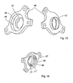
- zeigt zwei Ansichten des Gehäuses.
- Figur 16
- zeigt das Zusammenspiel der Wälzkörper mit dem Gehäuse.
- Figur 17
- zeigt den Schnappverschluss zwischen Gehäuse und Deckel in zwei Ansichten.
- Figur 18
- zeigt die Antriebsseite der erfindungsgemäßen Verstelleinrichtung.
- Figur 19
- zeigt die an der Einrichtung angeordnete Handhabe.
- Figur 20
- zeigt eine weitere Ansicht der Verstelleinrichtung mit der Handhabe.
- Figur 21
- zeigt eine 3-D-Darstellung der Antriebsseite der erfindungsgemäßen Verstelleinrichtung.
- Die in den folgenden Figuren beispielhaft und schematisch dargestellte Verstelleinrichtung 1 weist ein verripptes Gehäuse 2 beispielsweise aus Kunststoff 2, aus welchem die mit einer feinen Verzahnung versehene und im Gehäuse 2 gelagerte Antriebswelle 3 herausragt (
Fig. 1 ). Auf diese Verzahnung kann später ein Handrad zur manuellen Betätigung der Verstelleinrichtung 1 aufgesteckt oder ein Motor angeschlossen werden. Das Gehäuse 2 weist ferner Bohrungen 4 zur Befestigung der Verstelleinrichtung 1 auf, beispielsweise an dem seitlichen Träger der Metallstruktur eines Sitzteils. - Wie aus
Fig. 2 ersichtlich, ist das Gehäuse 2 innenseitig mit einer koaxial zur Antriebswelle 3 verlaufenden Innenverzahnung 5 versehen, in welcher drei Planetenzahnräder 6 um eine in das Gehäuse 2 hineinragende Außenverzahnung 7 der Antriebswelle 3 umlaufen. Bei einer Drehung der Antriebswelle 3 wandern die Achsen 8 der Planetenzahnräder 6 somit im Gehäuse 2 mit einer gegenüber der Antriebswelle 3 verringerten Drehzahl auf einer Kreisbahn. Die Antriebswelle 3 kann ein Kompensationsmittel, beispielsweise einen Kompensationsring aufweisen, mit dem Fertigungstolleranzen ausgeglichen, Geräusche vermindert und/oder ein fühlbarer Drehwiderstand erzeugt wird. Die Drehung der Antriebswelle 3 wird von einem ringförmigen Planetenträger 9 aufgenommen, der koaxial zur Antriebswelle 3 drehbar ist. Der Planetenträger weist aus seiner Axialfläche parallel zu seiner Drehachse in Richtung der Planetenzahnräder 6 auskragende Achsbolzen 10 auf. - Auf diesen Achsbolzen 10 sind die Planetenzahnräder 6 drehbar gelagert. Die zuvor beschriebenen Bauteile (Baugruppe A) bilden somit ein Planetengetriebe aus. Das Planetengetriebe ist in zwei Drehrichtungen drehbar.
- Der Planetenträger 9 ist die Schnittstelle zu einer freilaufartigen Bremseinrichtung (Baugruppe B), welche von der Abtriebsseite her auf die Verstelleinrichtung 1 einwirkende Drehmomente von dem Planetengetriebe (Baugruppe A) möglichst vollständig fernhalten soll. Diese Drehmomente können in zwei Drehrichtungen wirken. Die Baugruppe 13 besteht aus einem aus Stahlblech gestanzten Bremsring 11, der sich nach außen erstreckende Laschen 12 aufweist. Der Bremsring 11 wird in das komplementär geformte Gehäuse 2 eingeschoben, wobei sich Bohrungen 13 in den Laschen 12 mit den Bohrungen 4 des Gehäuses 2 decken. Der Bremsring 11 ist ferner mit einer kreisförmigen Ausnehmung 14 versehen, welche koaxial zur Antriebswelle 3 verläuft und den Innenring 15 der Bremseinrichtung aufnimmt.
- Im Spalt 16 zwischen dem Bremsring 11 und dem Innenring 15 (siehe
Fig. 3 ) sind paarweise zylinderförmige Wälzkörper 17, 17 angeordnet, wobei die Wälzkörper 17, 17' jedes Paares durch einen dazwischen liegenden, als Federmittel wirkenden Elastomerkörper 18 auseinander gespreizt werden. Der Fachmann erkennt, dass es sich aber auch um jedes beliebige andere Federmittel, beispielweise eine Spiralfeder handeln kann. Der Außenumfang des Innenrings 15 ist derart gestaltet, dass der Spalt 16 im Bereich jedes Elastomerblocks 18 größer als der Durchmesser der gleichartigen Wälzkörper 17, 17' ausgebildet ist, sich jedoch vom Elastomerblock 18 weg auf eine Höhe kleiner dem Durchmesser der Wälzkörper 17, 17' verengt. Jedes Paar von Wälzkörpern 17, 17' ist somit in einem Teilumfang des Spalts 16 gefangen. Bei der Drehung des Innenrings 15 relativ zum Bremsring 11 verklemmt sich, aufgrund einer Spiralgeometrie 36 an dem Innenrings 15 zum Wälzkörper 17, 17'hin, jeweils ein Wälzkörper 17 eines Paares im sich verengenden Bereich des Spalts 16, so dass eine weitere Drehung verhindert wird. Bei der Drehung des Innenrings 15 in Gegenrichtung erfolgt das Verklemmen durch den anderen Wälzkörper 17' des Paares. Somit wird verhindert, dass signifikante Drehmomente, die bei einem Unfall auftreten, auf das Planetengetriebe übertragen werden. - Der Planetenträger 9 ist auf seiner der Baugruppe A abgewandten Seite mit paarweisen Vorsprüngen 19, 19' ausgestattet, welche zwischen den Paaren von Wälzkörpern 17, 17' in den Spalt 16 hineinragen. Die Zwischenräume 21 zwischen jedem Paar von Vorsprüngen 19, 19' wirken spielbehaftet mit Ansätzen 20 auf dem Außenumfang des Innenrings 15 zusammen, während die den Zwischenräumen 21 abgewandten Flächen der Vorsprünge 19, 19' bei Drehung des Innenrings 15 alternativ auf die Wälzkörper 17, 17' einwirken. Bei der Drehung des Innenrings 15 werden hierdurch zunächst die verklemmten Wälzkörper 17, 17' gelöst, wobei das Spiel zwischen den Vorsprüngen 19 jedes Paares und den Ansätzen 20 aufgebraucht wird. Sobald jeder Vorsprung 19 am zugeordneten Ansatz 20 anliegt, wird unmittelbar ein Drehmoment vom Planetenträger 9 auf den Innenring 15 übertragen. Bei einer Drehung in Gegenrichtung erfolgt dies sinngemäß durch einen Kontakt zwischen den Ansätzen 20 und den Vorsprüngen 19'.
- Auf dem Innenring 15 ist auf der der Baugruppe A abgewandten Seite eine Anlaufscheibe 22 angeordnet, welche sich mit dem Innenring 15 dreht und an dem Gehäusedeckel 23 anliegt. Die Außenkontur des mit dem Gehäuse 2 verrastbaren Gehäusedeckels 23 ist deckungsgleich zum Bremsring 11 ausgebildet, so dass diese in gleicher Weise in das Gehäuse 2 eingesetzt werden können. Der Gehäusedeckel 23 ist mit einem koaxial zur Antriebswelle 2 ausgerichteten Durchzug 24 versehen, in welchem die Abtriebswelle 25 gelagert ist. In diesem Fall ist der Gehäusedeckel vorzugsweise aus einem metallischen Werkstoff gefertigt. Der Gehäusedeckel kann jedoch aus Kunststoff gefertigt sein für den Fall, dass er lediglich als Schutz benötigt wird. Der Gehäusedeckel wird an der vormontierten Einheit form- und/oder kraftschlüssig angebracht, beispielsweise angeschraubt oder angenietet. Vorzugsweise wird der Deckel 23 jedoch mit einem Schnellverschluss, beispielsweise einem Schnappverschluss, an dem Gehäuse 4 angebracht Die zur Antriebswelle 3 koaxial verlaufende Abtriebswelle 25 weist einen zur Lagerung geeigneten Zylinderbereich 26 auf, an den sich nach außen das Abtriebsritzel 27 anschließt. Auf der gegenüber liegenden Seite ist die Abtriebswelle 25 mit einem Polygonprofil 28 versehen, welches spielfrei in eine komplementär gestaltete Ausnehmung 29 im Innenring 15 eingreift. Der Fachmann erkennt, dass die Abtriebwelle 25 und der Innenring 15 einteilig ausgeführt sein können.
- Bei Betätigung der Verstelleinrichtung 1 wird das Antriebsmoment somit über die Antriebswelle 3, die Planetenzahnräder 6 und den Planetenträger 9 auf den Innenring 15 und von dort auf das Abtriebsritzel 25 übertragen. Ein von der Abtriebsseite her wirkendes Drehmoment wird über die Abtriebswelle 25 auf den Innenring 15 übertragen und nachfolgend durch Verklemmen der Wälzkörper 17 oder 17' vom Bremsring 11 abgefangen. Planententräger 9, Planentenzahnräder 6 und Gehäuse 2 werden hierdurch entlastet und können entsprechend schwächer dimensioniert werden.
- Die
Figuren 4 bis 9 zeigen verschiedene Konfigurationen von Bauteilen der Verstelleinrichtung 1 zueinander, wobei jeweils andere Bauteile ausgeblendet sind.Fig. 10 und 11 zeigen eine vordere oder hintere Ansicht der vormontierten Versteileinrichtung 1. -
Figur 12 zeigt eine weitere Darstellung der Bremseinrichtung gemäßFigur 3 . Es ist deutlich zu erkennen, wie der Vorsprung 20 zwischen jeweils zwei die Form- und/oder Kraftschlussmittel 19, 19' eingreift. -
Figur 13 zeigt eine andere Ausführungsform der Bremseinrichtung. In dem vorliegenden Fall ist das Form- und/oder Kraftschlussmittel 19 einteilig ausgeführt und weist einen Vorsprung, beispielsweise eine Nase 38 auf, die in eine Vertiefung 20 an dem Innenring 15 form- und/oder kraftschlüssig zusammenwirkt und das Kraftschlussmittel jeweils antreibt. -
Figur 14 zeigt eine weitere Darstellung der Explosionszeichnung gemäßFigur 2 . Deutlich ist der Kompensationsring 35 zu erkennen, der an der Schulter 37 anliegt und die Antriebswelle 3 umschließt. Weiterhin ist die Spiralgeometrie 36 an der Außenseite des Innenrings zu sehen. Ansonsten wird auf die Ausführungen zuFigur 2 verwiesen. - Die Lagerung der einzelnen Bauteile der Verstelleinrichtung 1 ist wie folgt gestaltet: Die Antriebswelle 3 ist über einen jenseits der Außenverzahnung 7 befindlichen zylinderförmigen Bereich 29 in einer Bohrung 30 im Gehäuse 2 sowie über einen diesseits der Außenverzahnung 7 hervorstehenden, einstückig angeformten Bolzen 31 in einer Bohrung 32 im Abtriebsritzel 25 gelagert. Der Planetenträger 9 lagert mit seinem Innenumfang 33 auf der äußeren Radialfläche eines Ringvorsprungs 34 des Innenrings 15. Die Abtriebswelle 25 ist über den Bereich 26 im Gehäusedeckel 23 und darüber hinaus über das Polyprofil 28 im Innenring 15 gelagert. Der Innenring 15 ist seinerseits über die Wälzkörper 17, 1 T relativ zum Bremsring 11 ausgerichtet.
-
Figur 15 zeigt das Gehäuse 46 der erfindungsgemäßen Verstelleinrichtung. Dieses weist eine radiale Anlagefläche 47 für das Abtriebsritzel sowie eine axiale Anlagefläche 48 sowie eine radiale Anlagefläche 49 für die Wälzkörper 17, 17' auf. Durch die kompakte Bauweise des Gehäuses ist es, wie inFigur 16 dargestellt, möglich, eine Verstelleinrichtung mit lediglich drei Wälzkörperpaaren 17, 17' zur Verfügung zu stellen und mit diesen drei Wälzkörperpaaren alle auftretenden Kräfte und Momente aufzunehmen und an das Gehäuse weiterzuleiten. -
Figur 17 zeigt das Gehäuse 46, dass mit einem Deckel 52 versehen ist. An dem Rand des Gehäuses 46 ist durch kaltverformen ein Verbindungsmittel 50 hergestellt worden, dass klippsend mit dem Deckel 52 zusammenwirkt, der eine Umlaufkante 51 aufweist. Durch diesen Schnappverschluss ist es möglich, den Deckel 52 werkzeuglos an dem Gehäuse 46 anzuordnen. - In
Figur 18 ist die Antriebsseite der Verstelleinrichtung dargestellt. Diese weist eine Anlagefläche 45 auf, an die eine Handhabe (nicht dargestellt) anlegbar ist, die mittels der Mutter 42 an einer Welle (nicht dargestellt) der Verstelleinrichtung befestigt wird. Desweiteren weist die Antriebsseite der erfindungsgemäßen Verstelleinrichtung fünf Vorsprünge 39 auf, zwischen denen und der Handhabe im Normalfall ein kleiner Spalt vorhanden ist, die jedoch als Anlage für die Handhabe dienen können, um eine Überbelastung der Anlagefläche 45 oder eine ungewollte Drehmomentübertragung auf die erfindungsgemäße Verstelleinrichtung zu vermeiden. Die Vorsprünge 39 sind in dem vorliegenden Fall äquidistal auf einem Kreisring um die Anlagefläche 45 für die Handhabe angeordnet. Dies muss jedoch nicht der Fall sein. Innerhalb dieser Krone von Vorsprüngen 39 ist eine Feder 41 angeordnet, die rückstellend mit der Handhabe zusammenwirkt. Die Vorsprünge 39 stellen einen Schutz für die Feder 41 dar, verhindern jedoch auch, dass sich ein Fahrzeuginsasse an der Feder verietzt. Einer der Vorsprünge 39'weist eine Einkerbung 54 auf, die die Feder 41 in zumindest zwei Richtung sichert. Desweiteren weist die erfindungsgemäße Verstelleinrichtung ein Vorspannmittel 40 auf, dass zum einen die Feder 41 vorspannt aber auch einer weiteren Befestigung der Feder an dem Gehäuse der Verstelleinrichtung dient. -
Figur 19 zeigt die an der Verstelleinrichtung angeordnete Handhabe 44. In dem vorliegenden Fall handelt es sich um einen Hebel, der in zwei Drehrichtungen bewegbar ist. Dieser Hebel liegt an der Anlagefläche 45 an und ist mittels der Schraube 42 an der Verstelleinrichtung befestigt. Aus der Handhabe sind die Mitnahmemittel 43 ausgeformt, die sich bei einer Bewegung der Handhabe auf dem Kreisring, auf dem die Vorsprünge angeordnet sind, bewegt. Das inFigur 19 dargestellte Mitnahmemittel wirkt mit der Anschlagfläche 53 der Vorsprünge 39 zusammen und begrenzt die Verstellbarkeit der Handhabe 44 in zwei Richtungen. -
Figur 20 zeigt eine weitere Darstellung der Handhabe im Zusammenspiel mit der erfindungsgemäßen Verstelleinrichtung. Aus dieser Ansicht ist zu erkennen, dass aus der Handhabe 44 zwei Mitnahmemittel 43 ausgeformt sind. Während das linke Mitnahmemittel die anhand vonFigur 19 erläuterte Funktion aufweist, wirkt das rechte Mitnahmemittel mit den Schenkeln der Feder 41 zusammen und nimmt je nach Drehrichtung einen dieser Schenkel mit und spannt dadurch die Feder 41. Sobald die Handhabe losgelassen wird, stellt die Feder 41 die Handhabe in ihre ursprüngliche Position zurück. -
Figur 21 zeigt eine weitere Darstellung der Antriebsseite der erfindungsgemäßen Verstelleinrichtung. Deutlich ist das Formschlussmittel 54 zu sehen, dass einen Schenkel der Feder 41 aufnimmt. Desweiteren ist zu erkennen, dass das Vorspannmittel die Feder 41 nicht nur vorspannt, sondern auch gegen Abheben sichert. - Die in den
Figuren 15 bis 21 dargestellte Verstelleinrichtung dient insbesondere zur Höhenverstellung der Sitzfläche eines Kraftfahrzeugsitzes. Der Fachmann erkennt, dass innerhalb des Gehäuses noch ein Freilauf angeordnet sein muss, der bei einer Rückstellung der Handhabe durch das Federmittel 41 verhindert, dass ein Drehmoment auf den Antrieb der Verstelleinrichtung ausgeübt wird. -
- 1
- Verstelleinrichtung
- 2
- Gehäuse
- 3
- Antriebswelle
- 4
- Bohrung
- 5
- Innenverzahnung
- 6
- Planetenzahnrad
- 7
- Außenverzahnung
- 8
- Achse
- 9
- Planetenträger
- 10
- Achsbolzen
- 11
- Bremsring
- 12
- Lasche
- 13
- Bohrung
- 14
- Ausnehmung
- 15
- Innenring
- 16
- Spalt
- 17, 17'
- Wälzkörper, Bremskörper
- 18
- Elastomerblock, Federmittel
- 19, 19'
- Vorsprung, Einbuchtung, Form- und/oder Kraftschlussmittel
- 20
- Ansatz, Vertiefung, Form- und/oder Kraftschlussmittel
- 21
- Zwischenraum
- 22
- Anlaufscheibe
- 23
- Gehäusedeckel
- 24
- Durchzug
- 25
- Abtriebswelle
- 26
- zylinderförmiger Bereich
- 27
- Abtriebsritzel
- 28
- Polygonprofil
- 29
- zylinderförmiger Bereich
- 30
- Bohrung
- 31
- Bolzen
- 32
- Bohrung
- 33
- Innenumfang
- 34
- Ringvorsprung
- 35
- Kompensationsmittel, Kompensationsring
- 36
- Mitnehmergeometrie, Spiralgeometrie
- 37
- Schulter
- 38
- Vorsprung, Nase
- 39, 39'
- Vorsprung
- 40
- Vorspannmittel
- 41
- Federmittel
- 42
- Befestigungsmittel
- 43
- Mitnahmemittel
- 44
- Handhabe
- 45
- Anlagefläche für die Handhabe
- 46
- Gehäuse
- 47
- radiale Ritzelanlagefläche
- 48
- axiale Wälzkörperanlagefläche
- 49
- radiale Wälzkörperanlagefläche
- 50
- Schnappverschluss, Clips
- 51
- Umlaufkante
- 52
- Verschlusselement, Deckel
- 53
- Anlagefläche
- 54
- Formschlussmittel
- A
- Planetenradgetriebe
- B
- Bremseinrichtung
Claims (17)
- Verstelleinrichtung (1) zur Durchführung mindestens einer Verstellfunktion, insbesondere zur Verstellung eines Kraftfahrzeugsitzes, mit einem Antrieb in Form eines Planetengetriebes (A), das einen Planetenträger (9) aufweist, und einem Abtrieb (25), der von einer Bremseinrichtung (B) bei nicht betätigtem Antrieb festgesetzt ist, dadurch gekennzeichnet, dass der Planetenträger so mit der Bremseinrichtung zusammenwirkt, dass diese wahlweise lösbar ist und dass der Planetenträger (9) Mittel (19, 19') aufweist, die mit Bremskörpern (17, 17') der Bremseinrichtung entriegelnd zusammenwirken.
- Verstelleinrichtung nach Anspruch 1 dadurch gekennzeichnet, dass die Bremseinrichtung in zwei Drehrichtungen wirkt.
- Verstelleinrichtung nach einem der voranstehenden Ansprüche, dadurch gekennzeichnet, dass die Bremseinrichtung einen Bremsring (11) und einen Innenring (15) aufweist, zwischen denen sich ein Spalt (16) befindet, in dem mindestens ein Bremskörper (17, 17') angeordnet ist.
- Verstelleinrichtung nach Anspruch 3, dadurch gekennzeichnet, dass Bremskörper (17, 17') paarweise angeordnet sind und jeweils ein Federmittel (18) aufweist, das zwischen den Bremskörpern (17, 17') angeordnet ist.
- Verstelleinrichtung nach einem der voranstehenden Ansprüche, dadurch gekennzeichnet, dass die Mittel (19, 19') des Planetenträgers Vorsprünge oder Vertiefungen (19, 19') sind.
- Verstelleinrichtung nach Anspruch 5, dadurch gekennzeichnet, dass der Planetenträger (9) mehrere paarweise angeordnete Vorsprünge (19, 19') aufweist und zwischen zwei Paaren von Vorsprüngen (19, 19') jeweils ein Zwischenraum (21) vorhanden ist.
- Verstelleinrichtung nach Anspruch 6, dadurch gekennzeichnet, dass in die Zwischenräumen (21) Ansätze (20) an dem Innenring (15) spielbehaftet eingreifen.
- Verstelleinrichtung nach einem der Ansprüche 3 - 7, dadurch gekennzeichnet, dass der Innenring (15) auf der den Wälzkörpern zugewandten Seite zumindest teilweise eine Mitnehmergeometrie (36), vorzugsweise eine Spiralgeometrie, aufweist.
- Verstelleinrichtung nach einem der voranstehenden Ansprüche, dadurch gekennzeichnet, dass eine Antriebswelle (3) zumindest teilweise in einer Abtriebswelle (25) gelagert ist.
- Verstelleinrichtung (1) nach einem der voranstehenden Ansprüche, dadurch gekennzeichnet, dass in einem Gehäuse (46) eine Lagerung für den Abtrieb (27) und die Bremseinrichtung (B) angeordnet ist.
- Verstelleinrichtung nach Anspruch 10, dadurch gekennzeichnet, dass an dem Gehäuse (2, 46) ein Schnappverschluss für ein Verschlusselement (52) angeordnet ist.
- Verstelleinrichtung nach einem der voranstehenden Ansprüche, dadurch gekennzeichnet, dass antriebsseitig eine Lagerfläche (45) für eine Handhabe (44) vorgesehen ist.
- Verstelleinrichtung nach einem der voranstehenden Ansprüche, dadurch gekennzeichnet, dass antriebsseitig Vorsprünge (39) als Anschlagflächen für eine Handhabe (44) vorgesehen sind.
- Verstelleinrichtung nach Anspruch 13, dadurch gekennzeichnet, dass innerhalb der Vorsprünge (39) ein Federmittel (41) angeordnet ist, dass rückstellend mit der Handhabe zusammenwirkt.
- Verstelleinrichtung nach Anspruch 13 oder 14, dadurch gekennzeichnet, dass ein Vorsprung (39') Formschlussmittel (54) für das Federmittel aufweist.
- Verstelleinrichtung nach einem der Ansprüche 13 - 15, dadurch gekennzeichnet, dass sie ein Vorspannmittel (40) für das Federmittel (41) aufweist.
- Verstelleinrichtung nach einem der voranstehenden Ansprüche, dadurch gekennzeichnet, dass an der Handhabe (44) ein Mitnahmemittel (43) für das Federmittel (41) angeordnet ist.
Priority Applications (1)
| Application Number | Priority Date | Filing Date | Title |
|---|---|---|---|
| PL07819486T PL2086790T3 (pl) | 2006-11-02 | 2007-10-30 | Urządzenie do regulacji, zwłaszcza siedzenia samochodowego |
Applications Claiming Priority (3)
| Application Number | Priority Date | Filing Date | Title |
|---|---|---|---|
| DE102006052185 | 2006-11-02 | ||
| DE102007017617.3A DE102007017617B4 (de) | 2006-11-02 | 2007-04-12 | Verstelleinrichtung eines Kraftfahrzeugsitzes |
| PCT/EP2007/009453 WO2008052761A1 (de) | 2006-11-02 | 2007-10-30 | Verstelleinrichtung, insbesondere für einen fahrzeugsitz |
Publications (2)
| Publication Number | Publication Date |
|---|---|
| EP2086790A1 EP2086790A1 (de) | 2009-08-12 |
| EP2086790B1 true EP2086790B1 (de) | 2013-12-11 |
Family
ID=38961096
Family Applications (1)
| Application Number | Title | Priority Date | Filing Date |
|---|---|---|---|
| EP07819486.7A Active EP2086790B1 (de) | 2006-11-02 | 2007-10-30 | Verstelleinrichtung, insbesondere für einen fahrzeugsitz |
Country Status (8)
| Country | Link |
|---|---|
| US (1) | US8672796B2 (de) |
| EP (1) | EP2086790B1 (de) |
| JP (1) | JP5352465B2 (de) |
| KR (1) | KR101376383B1 (de) |
| CN (1) | CN101553380B (de) |
| DE (1) | DE102007017617B4 (de) |
| PL (1) | PL2086790T3 (de) |
| WO (1) | WO2008052761A1 (de) |
Families Citing this family (43)
| Publication number | Priority date | Publication date | Assignee | Title |
|---|---|---|---|---|
| DE102007048788B4 (de) | 2007-06-04 | 2016-09-01 | Johnson Controls Gmbh | Vorrichtung zur Durchführung mindestens einer Verstellfunktion, insbesondere zur Verstellung eines Kraftfahrzeugsitzes und Fahrzeugsitz mit einer derartigen Vorrichtung |
| WO2009091980A1 (en) | 2008-01-17 | 2009-07-23 | Fisher Dynamics Corporation | Round recliner mechanism |
| DE102008052892B4 (de) | 2008-04-22 | 2014-09-11 | Johnson Controls Gmbh | Verstelleinrichtung |
| DE102008034800B4 (de) * | 2008-07-24 | 2016-02-11 | Johnson Controls Gmbh | Verstelleinrichtung, insbesondere für einen Fahrzeugsitz |
| DE102009010689B4 (de) * | 2009-02-27 | 2014-07-17 | Johnson Controls Gmbh | Höhenverstellung mit einem mehrteilig ausgeführten Abtriebsmittel |
| US8556762B2 (en) * | 2009-03-17 | 2013-10-15 | Crh North America, Inc. | Power seat height adjuster mechanism |
| EP2338725B1 (de) | 2009-12-17 | 2014-09-17 | Johnson Controls GmbH | Verstell- und Arretiervorrichtung |
| CN103140374B (zh) * | 2010-08-10 | 2016-10-05 | 约翰逊控股公司 | 具有调整装置的车辆座椅 |
| JP5827500B2 (ja) * | 2010-09-01 | 2015-12-02 | デルタ工業株式会社 | シートリフター及びシート |
| JP2012148752A (ja) * | 2010-12-28 | 2012-08-09 | Imasen Electric Ind Co Ltd | シート高さ調整クラッチ |
| WO2013010892A2 (de) * | 2011-07-20 | 2013-01-24 | C. Rob. Hammerstein Gmbh & Co. Kg | Verstellvorrichtung für einen kraftfahrzeugsitz mit mindestens einem anschlag |
| DE102011113747B4 (de) * | 2011-09-14 | 2025-01-23 | Keiper Seating Mechanisms Co., Ltd. | Beschlagsystem für einen Fahrzeugsitz und Fahrzeugsitz |
| JP2013112063A (ja) * | 2011-11-25 | 2013-06-10 | Delta Kogyo Co Ltd | リクライニング装置 |
| DE102012006058B4 (de) * | 2011-11-30 | 2014-05-15 | Johnson Controls Gmbh | Verstellvorrichtung und Verfahren zum Verstellen einer Kraftfahrzeugkomponente |
| DE102012006059B4 (de) * | 2011-11-30 | 2014-04-24 | Johnson Controls Gmbh | Verstellvorrichtung für einer Kraftfahrzeugkomponente |
| DE102012204354B3 (de) * | 2012-03-20 | 2013-09-05 | Schaeffler Technologies AG & Co. KG | Stützstruktur eines Planetenradträgers |
| DE102013210369A1 (de) | 2013-02-19 | 2014-08-21 | Johnson Controls Gmbh | Selbsthemmendes Getriebe |
| US9296315B2 (en) | 2013-02-26 | 2016-03-29 | Fisher & Company, Incorporated | Recliner mechanism with backdriving feature |
| CN103498891B (zh) * | 2013-10-16 | 2016-05-11 | 上海延锋江森座椅有限公司 | 一种具有间隙及阻尼调节功能的行星传动组件 |
| US9902297B2 (en) | 2014-06-11 | 2018-02-27 | Fisher & Company, Incorporated | Latch mechanism with locking feature |
| US10024392B2 (en) | 2015-08-25 | 2018-07-17 | Fisher & Company, Incorporated | Single-stage gear reduction output mechanism having a locking gear with pin receiving guide holes and anti-back drive capability for automotive seat adjuster drives |
| US9902295B2 (en) | 2015-08-25 | 2018-02-27 | Fisher & Company, Incorporated | Single-stage gear reduction output mechanism with a locking fork providing anti-back drive capability for automotive seat adjuster drives |
| US10195975B2 (en) | 2016-01-19 | 2019-02-05 | Fisher & Company, Incorporated | Gear assembly for a seat adjuster |
| US10843591B2 (en) | 2016-01-19 | 2020-11-24 | Fisher & Company, Incorporated | Gear assembly for a seat adjuster |
| US9963050B2 (en) | 2016-02-25 | 2018-05-08 | Ford Global Technologies Llc | Manual seat height adjuster mechanism |
| JP6682300B2 (ja) * | 2016-03-04 | 2020-04-15 | シロキ工業株式会社 | シートリクライニング装置 |
| US11273506B2 (en) | 2016-09-08 | 2022-03-15 | Fisher & Company, Incorporated | Open architecture power length adjuster assembly for a vehicle seat and method of manufacturing the same |
| US10953772B2 (en) | 2016-09-08 | 2021-03-23 | Fisher & Company, Incorporated | Open architecture power length adjuster assembly for a vehicle seat and method of manufacturing the same |
| US11766956B2 (en) | 2016-09-08 | 2023-09-26 | Fisher & Company, Incorporated | Open architecture power length adjuster assembly for a vehicle seat and method of manufacturing the same |
| US10583755B2 (en) * | 2017-08-02 | 2020-03-10 | Faurecia Automotive Seating, Llc | Recliner for a vehicle seat |
| JP7050446B2 (ja) * | 2017-09-25 | 2022-04-08 | 日本電産サンキョー株式会社 | 回転伝達機構およびダンパ装置 |
| DE102017130074B4 (de) * | 2017-12-15 | 2021-03-04 | Schaeffler Technologies AG & Co. KG | Stirnradgetriebe mit Sperrmechanismus |
| DE102018107765B3 (de) * | 2018-04-03 | 2019-03-07 | Schaeffler Technologies AG & Co. KG | Getriebeanordnung für eine Vorrichtung zur Niveauverstellung eines Fahrzeugaufbaus |
| US10625630B2 (en) * | 2018-07-03 | 2020-04-21 | Lear Corporation | Vehicle seating system |
| JP2020044855A (ja) * | 2018-09-14 | 2020-03-26 | 株式会社Tf−Metal | 自動車用シートのブレーキ装置 |
| WO2020146579A1 (en) | 2019-01-09 | 2020-07-16 | Fisher & Company, Incorporated | Power seat track assembly |
| US11760233B2 (en) | 2019-02-20 | 2023-09-19 | Fisher & Company, Incorporated | Ultra-compact power length adjuster with anti-back drive capability and pinion-rack output for a vehicle seat |
| DE102020123420B4 (de) | 2019-09-09 | 2023-05-04 | Adient Us Llc | Antriebseinrichtung für einen fahrzeugsitz sowie fahrzeugsitz |
| US11485255B2 (en) | 2020-05-01 | 2022-11-01 | Fisher & Company, Incorporated | Gearbox for vehicle seat adjustment mechanism |
| US11529892B2 (en) | 2020-05-01 | 2022-12-20 | Fisher & Company, Incorporated | Gearbox for vehicle seat adjustment mechanism |
| US12496937B2 (en) | 2022-10-12 | 2025-12-16 | Fisher & Company, Incorporated | Vehicle seat adjustment system with power long rails |
| US12503016B2 (en) | 2022-10-12 | 2025-12-23 | Fisher & Company, Incorporated | Vehicle seat adjustment assembly with reduced-backlash gear system |
| KR102768738B1 (ko) * | 2022-11-11 | 2025-02-14 | 대원정밀공업(주) | 유격방지 기능을 구비한 시트 스위블 장치 |
Family Cites Families (23)
| Publication number | Priority date | Publication date | Assignee | Title |
|---|---|---|---|---|
| GB1528357A (en) * | 1975-02-07 | 1978-10-11 | Ihw Eng Ltd | Seat reclining mechanism |
| DE3201309C2 (de) | 1982-01-18 | 1985-11-07 | Manfred Ing.(grad.) 4050 Mönchengladbach Lortz | Verstellmechanismus zur Drehverstellung zweier zentrisch gelagerter Bauteile |
| JPS58209630A (ja) * | 1982-05-31 | 1983-12-06 | Shiraki Kinzoku Kogyo Kk | シ−ト上下調整装置 |
| JPH01103436A (ja) | 1987-10-17 | 1989-04-20 | Fujiwara Kagaku Kk | 光反射性シート状成形物 |
| JPH0640516Y2 (ja) * | 1987-12-28 | 1994-10-26 | アイシン精機株式会社 | 自動車用パワーシート装置 |
| GB2220714B (en) * | 1988-07-14 | 1992-07-08 | Ntn Toyo Bearing Co Ltd | Clutch |
| US5025902A (en) * | 1990-01-04 | 1991-06-25 | Aichi Kikai Kogyo Kabushiki Kaisha | Bidirectional differential clutch |
| DE4321335C2 (de) * | 1993-06-26 | 1997-06-05 | Daimler Benz Ag | Verstellvorrichtung |
| DE4344627C1 (de) * | 1993-12-24 | 1995-05-04 | Benthin Ag | Rollvorhang |
| JPH082380A (ja) * | 1994-04-21 | 1996-01-09 | Nippon Seiko Kk | シートベルト用リトラクター |
| DE19718744C1 (de) * | 1997-05-02 | 1998-11-19 | Zahnradfabrik Friedrichshafen | Fahrzeuggetriebe mit integrierter Bremse |
| GB2343923B (en) * | 1998-11-06 | 2000-12-20 | Sam Tooling Ltd | Rotary couplings |
| DE19962225A1 (de) * | 1999-12-22 | 2001-06-28 | Breed Automotive Tech | Vorrichtung zur Verstellung der Neigung einer Rückenlehne eines Fahrzeugsitzes |
| US6279714B1 (en) * | 2000-01-18 | 2001-08-28 | Mobiletron Electronics Co., Ltd. | Powered, undirectional output controlling apparatus |
| JP2001327356A (ja) * | 2000-05-25 | 2001-11-27 | Tachi S Co Ltd | ラチェット式レバー機構 |
| JP4286444B2 (ja) * | 2000-10-13 | 2009-07-01 | Ntn株式会社 | クラッチユニット |
| WO2002064397A1 (de) * | 2001-02-12 | 2002-08-22 | Volkswagen Aktiengesellschaft | Verstelleinrichtung zur drehverstellung zweier zentrisch gelagerter adapterstücke, insbesondere für einen sitz vorzugsweise eines kraftfahrzeuges, und planetengetriebe hierfür |
| DE60215854T2 (de) * | 2001-03-08 | 2007-06-28 | Ntn Corp. | Rückwärtsfahrende Sperrkupplung |
| DE10129271A1 (de) * | 2001-06-18 | 2003-01-09 | Jan Klindworth | Sitzverstellgetriebe |
| DE10219199A1 (de) * | 2002-04-29 | 2003-11-06 | Hammerstein Gmbh C Rob | Lehnengelenkbeschlag für einen Kraftfahrzeugsitz |
| US6997847B2 (en) | 2004-01-27 | 2006-02-14 | L&P Property Management Company | Planetary gear actuator apparatus and method |
| JP4189760B2 (ja) | 2004-07-28 | 2008-12-03 | アイシン精機株式会社 | リクライニング装置 |
| JP4788338B2 (ja) * | 2005-12-28 | 2011-10-05 | アイシン精機株式会社 | 車両用シート調整装置 |
-
2007
- 2007-04-12 DE DE102007017617.3A patent/DE102007017617B4/de not_active Expired - Fee Related
- 2007-10-30 WO PCT/EP2007/009453 patent/WO2008052761A1/de not_active Ceased
- 2007-10-30 EP EP07819486.7A patent/EP2086790B1/de active Active
- 2007-10-30 CN CN2007800455255A patent/CN101553380B/zh active Active
- 2007-10-30 PL PL07819486T patent/PL2086790T3/pl unknown
- 2007-10-30 JP JP2009535022A patent/JP5352465B2/ja active Active
- 2007-10-30 US US12/447,861 patent/US8672796B2/en active Active
- 2007-10-30 KR KR1020097010970A patent/KR101376383B1/ko active Active
Also Published As
| Publication number | Publication date |
|---|---|
| JP5352465B2 (ja) | 2013-11-27 |
| PL2086790T3 (pl) | 2014-05-30 |
| KR101376383B1 (ko) | 2014-03-20 |
| US8672796B2 (en) | 2014-03-18 |
| EP2086790A1 (de) | 2009-08-12 |
| DE102007017617B4 (de) | 2016-06-09 |
| JP2010508198A (ja) | 2010-03-18 |
| CN101553380B (zh) | 2013-01-02 |
| DE102007017617A1 (de) | 2008-05-08 |
| KR20090082261A (ko) | 2009-07-29 |
| CN101553380A (zh) | 2009-10-07 |
| WO2008052761A1 (de) | 2008-05-08 |
| US20100139425A1 (en) | 2010-06-10 |
Similar Documents
| Publication | Publication Date | Title |
|---|---|---|
| DE102007017617B4 (de) | Verstelleinrichtung eines Kraftfahrzeugsitzes | |
| EP2307232B1 (de) | Verstelleinrichtung, insbesondere für einen fahrzeugsitz | |
| EP1893438B1 (de) | Beschlag für einen fahrzeugsitz | |
| DE102010019697B4 (de) | Beschlag für einen Fahrzeugsitz und Fahrzeugsitz | |
| DE102004013272B3 (de) | Neigungsverstellbeschlag für die Rückenlehne eines Kraftfahrzeugsitzes | |
| DE102004011268B3 (de) | Neigungsverstellbeschlag für die Rückenlehne eines Kraftfahrzeugsitzes | |
| DE102011107978B4 (de) | Verstellmechanismus und Fahrzeugsitz, der solch einen Verstellmechanismus umfasst | |
| DE102011106285B4 (de) | Beschlagsystem für einen Fahrzeugsitz und Fahrzeugsitz | |
| EP2539203B1 (de) | Verstellbare lenksäule für ein kraftfahrzeug | |
| DE102008063639B4 (de) | Gurtaufroller mit schaltbarem Gurtkraftbegrenzer | |
| EP2345569B1 (de) | Schraubradgetriebe für eine Lenkung eines Kraftfahrzeugs | |
| DE102010063044A1 (de) | Längsverstelleinrichtung mit einem Spindelhaltewinkel | |
| EP3915829A1 (de) | Fahrzeugsitzbeschlag und fahrzeugsitz | |
| EP1931534B1 (de) | Getriebe-antriebseinheit mit einem aufnahmemodul, insbesondere zum verstellen eines beweglichen teils im kraftfahrzeug | |
| DE19861276B4 (de) | Spindel- oder Schneckenantrieb für Verstelleinrichtungen in Kraftfahrzeugen | |
| EP2748028B1 (de) | Verstellbeschlag mit einem axialsperrsystem zur ablaufsicherung | |
| EP1412636A1 (de) | Starter | |
| EP0981461B1 (de) | Beidseitig wirkender antrieb | |
| DE102021209478B4 (de) | Gurtaufroller für einen Sicherheitsgurt | |
| DE1680242A1 (de) | Sitz,insbesondere fuer Kraftfahrzeuge | |
| DE102012007633B4 (de) | Fahrzeugsitz mit einem Verstellbeschlag | |
| DE102011115706B4 (de) | Verstellbeschlag | |
| DE102007050273B4 (de) | Feststell- und Neigungsverstellvorrichtung für Beschläge, insbesondere für einen Fahrzeugsitz | |
| DE102010003704A1 (de) | Getriebe-Antriebseinheit, insbesondere Sitzverstellungsantrieb | |
| DE102010026705A1 (de) | Beschlag für einen Fahrzeugsitz |
Legal Events
| Date | Code | Title | Description |
|---|---|---|---|
| PUAI | Public reference made under article 153(3) epc to a published international application that has entered the european phase |
Free format text: ORIGINAL CODE: 0009012 |
|
| 17P | Request for examination filed |
Effective date: 20090602 |
|
| AK | Designated contracting states |
Kind code of ref document: A1 Designated state(s): AT BE BG CH CY CZ DE DK EE ES FI FR GB GR HU IE IS IT LI LT LU LV MC MT NL PL PT RO SE SI SK TR |
|
| DAX | Request for extension of the european patent (deleted) | ||
| 17Q | First examination report despatched |
Effective date: 20120224 |
|
| GRAP | Despatch of communication of intention to grant a patent |
Free format text: ORIGINAL CODE: EPIDOSNIGR1 |
|
| INTG | Intention to grant announced |
Effective date: 20130621 |
|
| GRAS | Grant fee paid |
Free format text: ORIGINAL CODE: EPIDOSNIGR3 |
|
| GRAA | (expected) grant |
Free format text: ORIGINAL CODE: 0009210 |
|
| AK | Designated contracting states |
Kind code of ref document: B1 Designated state(s): AT BE BG CH CY CZ DE DK EE ES FI FR GB GR HU IE IS IT LI LT LU LV MC MT NL PL PT RO SE SI SK TR |
|
| REG | Reference to a national code |
Ref country code: GB Ref legal event code: FG4D Free format text: NOT ENGLISH |
|
| REG | Reference to a national code |
Ref country code: CH Ref legal event code: EP |
|
| REG | Reference to a national code |
Ref country code: AT Ref legal event code: REF Ref document number: 644338 Country of ref document: AT Kind code of ref document: T Effective date: 20140115 |
|
| REG | Reference to a national code |
Ref country code: IE Ref legal event code: FG4D Free format text: LANGUAGE OF EP DOCUMENT: GERMAN |
|
| REG | Reference to a national code |
Ref country code: DE Ref legal event code: R096 Ref document number: 502007012581 Country of ref document: DE Effective date: 20140206 |
|
| REG | Reference to a national code |
Ref country code: NL Ref legal event code: VDEP Effective date: 20131211 |
|
| PG25 | Lapsed in a contracting state [announced via postgrant information from national office to epo] |
Ref country code: LT Free format text: LAPSE BECAUSE OF FAILURE TO SUBMIT A TRANSLATION OF THE DESCRIPTION OR TO PAY THE FEE WITHIN THE PRESCRIBED TIME-LIMIT Effective date: 20131211 Ref country code: SE Free format text: LAPSE BECAUSE OF FAILURE TO SUBMIT A TRANSLATION OF THE DESCRIPTION OR TO PAY THE FEE WITHIN THE PRESCRIBED TIME-LIMIT Effective date: 20131211 Ref country code: FI Free format text: LAPSE BECAUSE OF FAILURE TO SUBMIT A TRANSLATION OF THE DESCRIPTION OR TO PAY THE FEE WITHIN THE PRESCRIBED TIME-LIMIT Effective date: 20131211 Ref country code: NL Free format text: LAPSE BECAUSE OF FAILURE TO SUBMIT A TRANSLATION OF THE DESCRIPTION OR TO PAY THE FEE WITHIN THE PRESCRIBED TIME-LIMIT Effective date: 20131211 |
|
| REG | Reference to a national code |
Ref country code: LT Ref legal event code: MG4D |
|
| PG25 | Lapsed in a contracting state [announced via postgrant information from national office to epo] |
Ref country code: CY Free format text: LAPSE BECAUSE OF FAILURE TO SUBMIT A TRANSLATION OF THE DESCRIPTION OR TO PAY THE FEE WITHIN THE PRESCRIBED TIME-LIMIT Effective date: 20131211 Ref country code: LV Free format text: LAPSE BECAUSE OF FAILURE TO SUBMIT A TRANSLATION OF THE DESCRIPTION OR TO PAY THE FEE WITHIN THE PRESCRIBED TIME-LIMIT Effective date: 20131211 |
|
| REG | Reference to a national code |
Ref country code: PL Ref legal event code: T3 |
|
| REG | Reference to a national code |
Ref country code: SK Ref legal event code: T3 Ref document number: E 15928 Country of ref document: SK |
|
| PG25 | Lapsed in a contracting state [announced via postgrant information from national office to epo] |
Ref country code: IS Free format text: LAPSE BECAUSE OF FAILURE TO SUBMIT A TRANSLATION OF THE DESCRIPTION OR TO PAY THE FEE WITHIN THE PRESCRIBED TIME-LIMIT Effective date: 20140411 Ref country code: EE Free format text: LAPSE BECAUSE OF FAILURE TO SUBMIT A TRANSLATION OF THE DESCRIPTION OR TO PAY THE FEE WITHIN THE PRESCRIBED TIME-LIMIT Effective date: 20131211 |
|
| PG25 | Lapsed in a contracting state [announced via postgrant information from national office to epo] |
Ref country code: RO Free format text: LAPSE BECAUSE OF FAILURE TO SUBMIT A TRANSLATION OF THE DESCRIPTION OR TO PAY THE FEE WITHIN THE PRESCRIBED TIME-LIMIT Effective date: 20131211 Ref country code: PT Free format text: LAPSE BECAUSE OF FAILURE TO SUBMIT A TRANSLATION OF THE DESCRIPTION OR TO PAY THE FEE WITHIN THE PRESCRIBED TIME-LIMIT Effective date: 20140411 Ref country code: ES Free format text: LAPSE BECAUSE OF FAILURE TO SUBMIT A TRANSLATION OF THE DESCRIPTION OR TO PAY THE FEE WITHIN THE PRESCRIBED TIME-LIMIT Effective date: 20131211 |
|
| REG | Reference to a national code |
Ref country code: DE Ref legal event code: R097 Ref document number: 502007012581 Country of ref document: DE |
|
| PLBE | No opposition filed within time limit |
Free format text: ORIGINAL CODE: 0009261 |
|
| STAA | Information on the status of an ep patent application or granted ep patent |
Free format text: STATUS: NO OPPOSITION FILED WITHIN TIME LIMIT |
|
| PG25 | Lapsed in a contracting state [announced via postgrant information from national office to epo] |
Ref country code: DK Free format text: LAPSE BECAUSE OF FAILURE TO SUBMIT A TRANSLATION OF THE DESCRIPTION OR TO PAY THE FEE WITHIN THE PRESCRIBED TIME-LIMIT Effective date: 20131211 |
|
| 26N | No opposition filed |
Effective date: 20140912 |
|
| REG | Reference to a national code |
Ref country code: DE Ref legal event code: R097 Ref document number: 502007012581 Country of ref document: DE Effective date: 20140912 |
|
| PG25 | Lapsed in a contracting state [announced via postgrant information from national office to epo] |
Ref country code: SI Free format text: LAPSE BECAUSE OF FAILURE TO SUBMIT A TRANSLATION OF THE DESCRIPTION OR TO PAY THE FEE WITHIN THE PRESCRIBED TIME-LIMIT Effective date: 20131211 |
|
| PG25 | Lapsed in a contracting state [announced via postgrant information from national office to epo] |
Ref country code: LU Free format text: LAPSE BECAUSE OF FAILURE TO SUBMIT A TRANSLATION OF THE DESCRIPTION OR TO PAY THE FEE WITHIN THE PRESCRIBED TIME-LIMIT Effective date: 20141030 Ref country code: MC Free format text: LAPSE BECAUSE OF FAILURE TO SUBMIT A TRANSLATION OF THE DESCRIPTION OR TO PAY THE FEE WITHIN THE PRESCRIBED TIME-LIMIT Effective date: 20131211 |
|
| REG | Reference to a national code |
Ref country code: CH Ref legal event code: PL |
|
| GBPC | Gb: european patent ceased through non-payment of renewal fee |
Effective date: 20141030 |
|
| PG25 | Lapsed in a contracting state [announced via postgrant information from national office to epo] |
Ref country code: BE Free format text: LAPSE BECAUSE OF NON-PAYMENT OF DUE FEES Effective date: 20141031 |
|
| REG | Reference to a national code |
Ref country code: IE Ref legal event code: MM4A |
|
| PG25 | Lapsed in a contracting state [announced via postgrant information from national office to epo] |
Ref country code: CH Free format text: LAPSE BECAUSE OF NON-PAYMENT OF DUE FEES Effective date: 20141031 Ref country code: LI Free format text: LAPSE BECAUSE OF NON-PAYMENT OF DUE FEES Effective date: 20141031 Ref country code: GB Free format text: LAPSE BECAUSE OF NON-PAYMENT OF DUE FEES Effective date: 20141030 |
|
| REG | Reference to a national code |
Ref country code: FR Ref legal event code: PLFP Year of fee payment: 9 |
|
| PG25 | Lapsed in a contracting state [announced via postgrant information from national office to epo] |
Ref country code: IE Free format text: LAPSE BECAUSE OF NON-PAYMENT OF DUE FEES Effective date: 20141030 |
|
| REG | Reference to a national code |
Ref country code: AT Ref legal event code: MM01 Ref document number: 644338 Country of ref document: AT Kind code of ref document: T Effective date: 20141030 |
|
| PG25 | Lapsed in a contracting state [announced via postgrant information from national office to epo] |
Ref country code: AT Free format text: LAPSE BECAUSE OF NON-PAYMENT OF DUE FEES Effective date: 20141030 |
|
| PG25 | Lapsed in a contracting state [announced via postgrant information from national office to epo] |
Ref country code: BG Free format text: LAPSE BECAUSE OF FAILURE TO SUBMIT A TRANSLATION OF THE DESCRIPTION OR TO PAY THE FEE WITHIN THE PRESCRIBED TIME-LIMIT Effective date: 20131211 |
|
| PG25 | Lapsed in a contracting state [announced via postgrant information from national office to epo] |
Ref country code: IT Free format text: LAPSE BECAUSE OF FAILURE TO SUBMIT A TRANSLATION OF THE DESCRIPTION OR TO PAY THE FEE WITHIN THE PRESCRIBED TIME-LIMIT Effective date: 20131211 Ref country code: GR Free format text: LAPSE BECAUSE OF FAILURE TO SUBMIT A TRANSLATION OF THE DESCRIPTION OR TO PAY THE FEE WITHIN THE PRESCRIBED TIME-LIMIT Effective date: 20140312 |
|
| PG25 | Lapsed in a contracting state [announced via postgrant information from national office to epo] |
Ref country code: MT Free format text: LAPSE BECAUSE OF FAILURE TO SUBMIT A TRANSLATION OF THE DESCRIPTION OR TO PAY THE FEE WITHIN THE PRESCRIBED TIME-LIMIT Effective date: 20131211 Ref country code: TR Free format text: LAPSE BECAUSE OF FAILURE TO SUBMIT A TRANSLATION OF THE DESCRIPTION OR TO PAY THE FEE WITHIN THE PRESCRIBED TIME-LIMIT Effective date: 20131211 Ref country code: HU Free format text: LAPSE BECAUSE OF FAILURE TO SUBMIT A TRANSLATION OF THE DESCRIPTION OR TO PAY THE FEE WITHIN THE PRESCRIBED TIME-LIMIT; INVALID AB INITIO Effective date: 20071030 |
|
| REG | Reference to a national code |
Ref country code: FR Ref legal event code: PLFP Year of fee payment: 10 |
|
| REG | Reference to a national code |
Ref country code: DE Ref legal event code: R081 Ref document number: 502007012581 Country of ref document: DE Owner name: KEIPER SEATING MECHANISMS CO., LTD., CN Free format text: FORMER OWNER: JOHNSON CONTROLS GMBH, 51399 BURSCHEID, DE Ref country code: DE Ref legal event code: R081 Ref document number: 502007012581 Country of ref document: DE Owner name: ADIENT LUXEMBOURG HOLDING S.A R.L., LU Free format text: FORMER OWNER: JOHNSON CONTROLS GMBH, 51399 BURSCHEID, DE Ref country code: DE Ref legal event code: R081 Ref document number: 502007012581 Country of ref document: DE Owner name: ADIENT LUXEMBOURG HOLDING S.A.R.L., LU Free format text: FORMER OWNER: JOHNSON CONTROLS GMBH, 51399 BURSCHEID, DE |
|
| REG | Reference to a national code |
Ref country code: FR Ref legal event code: PLFP Year of fee payment: 11 |
|
| REG | Reference to a national code |
Ref country code: DE Ref legal event code: R081 Ref document number: 502007012581 Country of ref document: DE Owner name: KEIPER SEATING MECHANISMS CO., LTD., CN Free format text: FORMER OWNER: ADIENT LUXEMBOURG HOLDING S.A.R.L., LUXEMBOURG, LU Ref country code: DE Ref legal event code: R081 Ref document number: 502007012581 Country of ref document: DE Owner name: ADIENT LUXEMBOURG HOLDING S.A R.L., LU Free format text: FORMER OWNER: ADIENT LUXEMBOURG HOLDING S.A.R.L., LUXEMBOURG, LU |
|
| REG | Reference to a national code |
Ref country code: FR Ref legal event code: PLFP Year of fee payment: 12 |
|
| REG | Reference to a national code |
Ref country code: SK Ref legal event code: PC4A Ref document number: E 15928 Country of ref document: SK Owner name: ADIENT LUXEMBOURG HOLDING S.A R.L., LUXEMBOURG, LU Free format text: FORMER OWNER: JOHNSON CONTROLS GMBH, BURSCHEID, DE Effective date: 20210120 |
|
| REG | Reference to a national code |
Ref country code: DE Ref legal event code: R082 Ref document number: 502007012581 Country of ref document: DE Representative=s name: KUTZENBERGER WOLFF & PARTNER PATENTANWALTSPART, DE Ref country code: DE Ref legal event code: R081 Ref document number: 502007012581 Country of ref document: DE Owner name: KEIPER SEATING MECHANISMS CO., LTD., CN Free format text: FORMER OWNER: ADIENT YANFENG SEATING MECHANISMS CO., LTD., SHANGHAI, CN Ref country code: DE Ref legal event code: R081 Ref document number: 502007012581 Country of ref document: DE Owner name: KEIPER SEATING MECHANISMS CO., LTD., CN Free format text: FORMER OWNER: ADIENT LUXEMBOURG HOLDING S.A R.L., LUXEMBOURG, LU Ref country code: DE Ref legal event code: R082 Ref document number: 502007012581 Country of ref document: DE Representative=s name: LIEDTKE & PARTNER PATENTANWAELTE, DE |
|
| REG | Reference to a national code |
Ref country code: SK Ref legal event code: TC4A Ref document number: E 15928 Country of ref document: SK Owner name: KEIPER SEATING MECHANISMS CO., LTD., PUDONG, S, CN Effective date: 20211124 Ref country code: SK Ref legal event code: PC4A Ref document number: E 15928 Country of ref document: SK Owner name: ADIENT YANFENG SEATING MECHANISMS CO., LTD, PU, CN Free format text: FORMER OWNER: ADIENT LUXEMBOURG HOLDING S.A R.L., LUXEMBOURG, LU Effective date: 20211124 |
|
| REG | Reference to a national code |
Ref country code: DE Ref legal event code: R082 Ref document number: 502007012581 Country of ref document: DE Representative=s name: KUTZENBERGER WOLFF & PARTNER PATENTANWALTSPART, DE |
|
| PGFP | Annual fee paid to national office [announced via postgrant information from national office to epo] |
Ref country code: PL Payment date: 20250827 Year of fee payment: 19 |
|
| PGFP | Annual fee paid to national office [announced via postgrant information from national office to epo] |
Ref country code: FR Payment date: 20250908 Year of fee payment: 19 |
|
| PGFP | Annual fee paid to national office [announced via postgrant information from national office to epo] |
Ref country code: SK Payment date: 20250923 Year of fee payment: 19 |
|
| PGFP | Annual fee paid to national office [announced via postgrant information from national office to epo] |
Ref country code: DE Payment date: 20250902 Year of fee payment: 19 |
|
| PGFP | Annual fee paid to national office [announced via postgrant information from national office to epo] |
Ref country code: CZ Payment date: 20251021 Year of fee payment: 19 |