EP1359051A2 - Lehnengelenkbeschlag für einen Kraftfahrzeugsitz - Google Patents
Lehnengelenkbeschlag für einen Kraftfahrzeugsitz Download PDFInfo
- Publication number
- EP1359051A2 EP1359051A2 EP03000112A EP03000112A EP1359051A2 EP 1359051 A2 EP1359051 A2 EP 1359051A2 EP 03000112 A EP03000112 A EP 03000112A EP 03000112 A EP03000112 A EP 03000112A EP 1359051 A2 EP1359051 A2 EP 1359051A2
- Authority
- EP
- European Patent Office
- Prior art keywords
- backrest
- joint
- folding
- arm
- bearing bore
- Prior art date
- Legal status (The legal status is an assumption and is not a legal conclusion. Google has not performed a legal analysis and makes no representation as to the accuracy of the status listed.)
- Granted
Links
- 239000002184 metal Substances 0.000 claims description 3
- 230000000903 blocking effect Effects 0.000 description 14
- 238000010276 construction Methods 0.000 description 4
- 230000004888 barrier function Effects 0.000 description 3
- 229910000831 Steel Inorganic materials 0.000 description 1
- 230000002349 favourable effect Effects 0.000 description 1
- 210000000245 forearm Anatomy 0.000 description 1
- 239000000463 material Substances 0.000 description 1
- 125000006850 spacer group Chemical group 0.000 description 1
- 239000010959 steel Substances 0.000 description 1
Images


Classifications
-
- B—PERFORMING OPERATIONS; TRANSPORTING
- B60—VEHICLES IN GENERAL
- B60N—SEATS SPECIALLY ADAPTED FOR VEHICLES; VEHICLE PASSENGER ACCOMMODATION NOT OTHERWISE PROVIDED FOR
- B60N2/00—Seats specially adapted for vehicles; Arrangement or mounting of seats in vehicles
- B60N2/02—Seats specially adapted for vehicles; Arrangement or mounting of seats in vehicles the seat or part thereof being movable, e.g. adjustable
- B60N2/20—Seats specially adapted for vehicles; Arrangement or mounting of seats in vehicles the seat or part thereof being movable, e.g. adjustable the back-rest being tiltable, e.g. to permit easy access
-
- B—PERFORMING OPERATIONS; TRANSPORTING
- B60—VEHICLES IN GENERAL
- B60N—SEATS SPECIALLY ADAPTED FOR VEHICLES; VEHICLE PASSENGER ACCOMMODATION NOT OTHERWISE PROVIDED FOR
- B60N2/00—Seats specially adapted for vehicles; Arrangement or mounting of seats in vehicles
- B60N2/02—Seats specially adapted for vehicles; Arrangement or mounting of seats in vehicles the seat or part thereof being movable, e.g. adjustable
- B60N2/22—Seats specially adapted for vehicles; Arrangement or mounting of seats in vehicles the seat or part thereof being movable, e.g. adjustable the back-rest being adjustable
- B60N2/225—Seats specially adapted for vehicles; Arrangement or mounting of seats in vehicles the seat or part thereof being movable, e.g. adjustable the back-rest being adjustable by cycloidal or planetary mechanisms
- B60N2/2251—Seats specially adapted for vehicles; Arrangement or mounting of seats in vehicles the seat or part thereof being movable, e.g. adjustable the back-rest being adjustable by cycloidal or planetary mechanisms with gears having orbital motion, e.g. sun and planet gears
Definitions
- the invention relates to a backrest joint fitting for a Motor vehicle seat, in particular for a vehicle seat that can be advanced. she is particularly suitable for vehicles with access to a rear seat a single vehicle door per vehicle side, i.e. for so-called two-door Motor vehicles.
- the invention relates to such a vehicle seat, the backrest (Backrest) and has a seat support.
- a vehicle seat usually belongs to one such a vehicle seat also has a base, for example is adjustable in height, and a longitudinal adjustment device with two Rail pairs.
- the backrest is over the Backrest joint fitting fixed on the seat support.
- Anybody under seat support understood any structure that directly or indirectly supports a seat cushion.
- Such forward-moving vehicle seats on the one hand a folding arm for quickly folding the backrest out of one Use position in a folding position and on the other hand adjustable hinge with which the backrest opposite the seat support is adjustable in angle, this takes place in the use position of the backrest and within a useful angle range.
- a motor vehicle seat is known from the prior art in which the adjustable between the two arms of the backrest joint fitting Joint, also called backrest joint, is provided.
- the lower arm the backrest joint fitting is not rigidly connected to the seat support, rather hinged to a hinge point on the seat support and via a Detachable connection, for example a hook, otherwise on the seat support or a part connected to it. Will the detachable If the connection is released, the backrest can move forward around the pivot point be pivoted.
- the folding joint itself is not assigned to the backrest joint fitting. Furthermore, it is not achievable that the folding axis and the articulated axis coincide. Under Folding axis is understood to be the axis around which the swiveling takes place.
- the hinge axis is the axis of the adjustable hinge about this axis the backrest is adjusted in the use position.
- the invention has for its object a backrest joint fitting specify a motor vehicle seat, which both the folding joint as also has the adjustable joint, which is basically the possibility offers, folding axis and articulated axis of the adjustable joint to arrange the same axis line, which is suitable for both manual and motorized adjustment is suitable and is based on less movement than the known devices can be interpreted.
- this type of backrest fitting is both the pre-folding joint and the adjustable joint between the both arms arranged.
- the backrest joint fitting unit offers thus both functions realized in one component. It is not necessary, separate components, for example for the folding joint, on To provide a motor vehicle seat. Due to the combined training in only One fitting simplifies construction, assembly, storage, etc.
- adjustable joint no longer mechanically parallel to the folding joint, rather, both are arranged one after the other (serially). Makes mechanical this is noticeable in that the adjustable joint is not directly between the two arms, but between one arm and the bearing part is arranged or acts.
- the folding joint is between the other arm and the bearing part.
- the bearing bore is relatively large Executed diameter, the bearing part is designed accordingly. This allows the bearing play in the folding joint to be reduced. Farther a compact design is made possible because of the adjustable joint can be accommodated within the bearing part, the bearing part can be formed for example as a ring. Great Diameter becomes a diameter of e.g. 6 to 12 cm, especially 10 cm understood.
- the pre-folding axis falls over which folds forward and the hinge axis of the adjustable hinge together. This enables the bearing clearance to be further reduced.
- the backrest can be designed so that only its movement around which must take into account a common axis, but not by two different, offset axes.
- the bearing bore is preferably formed in the upper arm.
- the locking device can also be assigned to the upper arm, which again a favorable mechanical connection between the release means and a release lever. This mechanical connection must now no longer be guided over a joint, rather it remains within the Rest.
- the two arms and the Flat sheet metal parts This makes the inner joint flat, lightweight and from inexpensive and very precisely producible Build up components.
- the lower arm preferably consists of two flat ones Partial arms that hold the upper arm between them and thus a part take over the housing that the backrest joint fitting to the outside concludes.
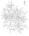
- Figure 1 shows a motor vehicle seat with the back joint fitting is equipped.
- the motor vehicle seat has a seat support 20 and a backrest 22.
- the backrest joint fitting is arranged between the two.
- the seat support 20 is only hinted at here, it carries one directly or indirectly Upholstery body 24 and is with front and rear parallelogram arms a longitudinal adjustment unit 26 articulated, which consists of two pairs of rails consists. All of this is state of the art and does not need to be discussed here are explained.
- the back hinge fitting has one on the seat support 22 rigidly attachable lower arm 28 and a rigid on the back 22 attachable upper arm 30.
- the difference between the lower arm 28 and seat support 20 as "rigid" be clearly expressed regarding the state of the art.
- the lower arm 28 is in two attachment points 32 connected to the seat support 20. These fortifications are permanent cannot be solved as in the prior art.
- the attachment takes place in four attachment points 34th
- the lower arm consists of two arms 281 (front arm) and 282 (rear arm). Both arms are identical. Like the upper arm 30, they are made of flat material, in particular Sheet steel, manufactured. When the backrest joint fitting is installed the upper arm 30 between the two partial arms 281 and 282 and in Contact with these.
- the upper arm 30 has a bearing bore 50. It is a circular recess with an inner diameter of several Centimeters, for example 5 to 12, in particular 9 to 11 cm.
- the Bearing bore 50 goes upwards, that is to the bores 44, over in a barrier 52, which has a complicated shape and on the still individual is received.
- a stop bay 54 is provided, which is also in the bearing bore 50 empties.
- the folding joint 48 is described in the following:
- a bearing part 60 is pivotally mounted within the bearing bore. It lies with its cylindrical outer jacket as free of play as possible Inner wall of the bearing bore 50.
- the bearing part 60 is within the Bearing bore 50 can only be rotated over a limited swivel angle, namely the desired pivot lever of the pre-folding movement.
- the Limitation is achieved by stops, which are discussed below becomes.
- a locking lug 62 protrudes upward, the radial stands out from the ideal cylindrical outer shell of the bearing part 60. It engages in the bay 52. In the position shown in Figure 3 the locking lug 62 is in play-free contact on a locking flank 64 the locking bay 52.
- the locking lug 62 has two main stages rounded edges, the blocking edge 64 is also designed accordingly. This system of the locking lug 62 on the locking flank 64 is one Rotational movement of the bearing part 60 clockwise (see Figure 3) blocked. In Figures 1 and 2, the locking direction is exactly in the other direction.
- FIG 3 shows a rotary movement of the bearing part 60 counterclockwise and within the bearing bore 50 thereby prevented that a double-armed locking member 66 with an end face of a lower locking arm rests on a blocking surface 68 of the locking lug 62, this blocking surface 68 points in the opposite direction to the blocking edge 64.
- the blocking edge 68 and the end face of the locking part 66 intersect very much small angle and in the area of self-locking.
- the locking part 66 is so far in the clockwise direction around its locking part axis 70 a suitable, elastic means (not shown, known per se) rotated that there is a play-free blocking.
- a straight line through the Blocking part axis 70 and the contact area between blocking surface 68 the spermase 62 and free end of the lower arm of 66 runs in essentially perpendicular to a diameter line through the Blocking surface 68 in the blocked state. The deviation from the right angle is in the area of self-locking.
- a stop flank 72 is located opposite the locking flank 60 the blocking bay 52.
- the blocking surface 68 strikes this, if that Locking part 66 is pivoted away and thus the blocking is released.
- the locking part 66 is located entirely within the locking bay 52. This also applies to a release lever 74 which is about a release lever axis 76 is pivotable. Figure 3 shows the rest position of the release lever 74. In it is preloaded elastically. The release lever 74 turns clockwise swiveled, he hits a second, short arm of the two-armed locking part 66. This turns it counterclockwise pivoted. This allows the free end of the longer arm of the locking part Swing 66 away from the blocking surface 68.
- a Bowden cable 78 engages the release lever 74, which is at its other end with a lever 80, which in itself in the upper region of the backrest 22 is provided in a known manner, is connected.
- the Bowden cable 78 can also be a simple cable pull.
- the parts 62 to 80 form one Locking device 61.
- the parts 72 to 80 form one of these Release device of this locking device 61.
- the release lever 74 has the Function of a release agent, it is therefore also used as a release agent designated.
- a stop part 82 jumps radially from the bearing part 60 into the stop bay 54 in front. It forms additional stops. So is shown in Figure 3 Locked position the left radial flank of the stop part 82 in the stop on left end of the stop bay 54. If the bearing part 60 after the release of the Locking device was rotated and the blocking surface 68 on the Stop flank 72 is present, the other radial flank of the stop part 82 at the other end of the stop bay 54.
- housing parts 86, 88 On both sides of the upper arm 30 and essentially in the area around the Barrier 52 around cover two housing parts 86, 88, which essentially are mirror images of identical construction, from the side, they cover in essentially the barrier 52 and the levers 66 and 74. In them are the Locking part axis 70 and the release lifting axis 76 positioned. Continue to educate they have a curved slot 88 that indicates the movement of the point of attack of the Bowden cable 78 on the release lever 74. After all, the two have Housing parts 86, 88 a guide edge lying on a circular arc 90, with which they each overlap a partial arm 281 or 282 and so hold that it can be rotated relative to them.
- the bearing part 60 is essentially designed as a ring. It was on Inner jacket a toothing 92. A corresponding inner toothing 94, but with a different number of teeth, the two have identical partial arms 281, 282. With these toothings 92, 94 there are three Planet gears 96 engaged, the planet gears 96 are equally distributed arranged. They are in turn in engagement with a pinion 98, which with a Shaft 100 is connected. The axis of this wave runs through the Center of the bearing bore 50 and the center of the toothing 92, and perpendicular to the plane in which the flat sheet metal part upper arm 30 located.
- the shaft 100 protrudes to the outside in front.
- a connecting means 110 is provided on this shaft and can be a Handwheel (not shown) with which the planetary gear is drivable.
- An electric motor can also be used instead of the handwheel be used.
- the parts 92 to 100 form an adjustable joint 106 for Angle adjustment of the backrest 22 in its position of use.
- the folding joint 48 and adjustable joint 106 mechanically arranged in series.
- the Locking device 61 blocks the pivoting movement of the bearing part 60 in the Bearing bore 50. A swiveling forward takes place by relative movement between upper arm 30 and bearing part 60.
- the adjustable joint is again located between the bearing part 60 and the lower arm 28.
- the components cannot be built concentrically or from the inside out, rather can they are also laterally offset.
- the adjustable joint 106 does not have to be like in the exemplary embodiment, essentially within the bearing bore 50 be accommodated, although this arrangement offers advantages.
Landscapes
- Engineering & Computer Science (AREA)
- Aviation & Aerospace Engineering (AREA)
- Transportation (AREA)
- Mechanical Engineering (AREA)
- Chairs For Special Purposes, Such As Reclining Chairs (AREA)
- Seats For Vehicles (AREA)
Abstract
Description
Claims (10)
- Lehnengelenkbeschlag für einen Kraftfahrzeugsitz, der einen Sitzträger (20) und eine Lehne (22) aufweist, insbesondere Lehnengelenkbeschlag für Kraftfahrzeuge mit nur einer Tür pro Fahrzeugseite, der Lehnengelenkbeschlag weist aufe) einen am Sitzträger (20) starr befestigbaren unteren Arm (28),f) einen an der Lehne (22) starr befestigbaren oberen Arm(30),g) ein Vorklappgelenk (48) zum raschen Vorklappen der Lehne (22) aus einer Gebrauchsstellung in eine Vorklappstellung, das eine Lagerbohrung (50) in einem der beiden Arme (28, 30), ein in dieser Lagerbohrung (50) schwenkbar angeordnetes Lagerteil (60) und eine Sperreinrichtung (61) aufweist, die eine Schwenkbewegung des Lagerteils (60) in der Lagerbohrung (50) normalerweise sperrt und der ein Freigabemittel zugeordnet ist, das bei Betätigung die Sperreinrichtung (61) freigibt, wenn ein Vorklappen in die Vorklappstellung erfolgen soll undh) mit einem zwischen dem Lagerteil (60) und dem anderen Arm (30, 28) angeordneten, einstellbaren Gelenk (106) zur Winkelverstellung der Lehne (22) gegenüber dem Sitzträger (20) in der Gebrauchsstellung der Lehne (22) und innerhalb eines Nutzwinkelbereichs der Lehne (22).
- Lehnengelenkbeschlag nach Anspruch 1, dadurch gekennzeichnet, dass die Lagerbohrung (50) im oberen Arm (30) ausgebildet ist.
- Lehnengelenkbeschlag nach Anspruch 1, dadurch gekennzeichnet, dass das Lagerteil (60) in der Lagerbohrung (50) des einen Arms (28, 30) um eine Vorklappachse verschwenkbar angeordnet ist und dass das einstellbare Gelenk (106) um eine Gelenkachse einstellbar ist, die mit der Vorklappachse zusammenfällt.
- Lehnengelenkbeschlag nach Anspruch 1, dadurch gekennzeichnet, dass die Lagerbohrung (50) einen größeren Durchmesser hat als das einstellbare Gelenk (106), und dass sich das einstellbare Gelenk (106) innerhalb eines durch die Lagerbohrung (50) definierten Zylinders befindet, insbesondere zumindest teilweise innerhalb der Lagerbohrung (50) angeordnet ist.
- Lehnengelenkbeschlag nach Anspruch 1, dadurch gekennzeichnet, dass das Lagerteil (60) ein Ring, insbesondere eine Ringscheibe, ist, der an seinem Außenmantel an der Lagerbohrung (50) anliegt und der an seinem Innenmantel einen Teilbereich des einstellbaren Gelenks (106), insbesondere eine Innenverzahnung (94), ausbildet.
- Lehnengelenkbeschlag nach Anspruch 1, dadurch gekennzeichnet, dass das Lagerteil (60) ein erstes Anschlagmittel, insbesondere eine radial vorspringende Sperrnase, aufweist, dass der eine Arm (28, 30) ein zweites Anschlagmittel, insbesondere eine Anschlagflanke (62), aufweist und dass diese beiden Anschlagmittel die Vorklappbewegung der Lehne (22) in die Vorklappstellung begrenzen.
- Lehnengelenkbeschlag nach Anspruch 1, dadurch gekennzeichnet, dass der eine Arm (28, 30) eine Sperrbucht (52) aufweist, die mit der Lagerbohrung (50) verbunden ist und dass sich in dieser Sperrbucht (52) ein Sperrteil (66) und vorzugsweise auch ein Lösehebel (74) der Sperreinrichtung (61) befinden.
- Lehnengelenkbeschlag nach Anspruch 1, dadurch gekennzeichnet, dass die beiden Arme (28, 30) und das Lagerteil (60) flache Blechteile sind, insbesondere dass der untere Arm (28) aus zwei flachen Teilarmen (281, 282) besteht, die zwischen sich den oberen Arm (30) aufnehmen.
- Lehnengelenkbeschlag nach Anspruch 1, dadurch gekennzeichnet, dass das einstellbare Gelenk (106) eine Antriebswelle und ein Getriebe aufweist und dass die Antriebswelle ein Verbindungsmittel (110) hat für eine Verbindung mit einem Motor oder einem Handbetätigungsmittel, z. B. Handrad, Handhebel.
- Lehnengelenkbeschlag nach Anspruch 1, dadurch gekennzeichnet, dass das einstellbare Gelenk (106) auf nur eine Sitzseite und die Sperreinrichtung (61) des Vorklappgelenks (48) nur auf der anderen Sitzseite des Kraftfahrzeugsitzes angeordnet sind, dass die Schwenkachse des einstellbaren Gelenks (106) mit der Vorklappachse des Vorklappgelenks (48) zusammenfällt und dass eine starre Drehverbindung vorgesehen ist, die zwischen den beiden Gelenken (106) der beiden Sitzseiten angeordnet ist.
Applications Claiming Priority (2)
| Application Number | Priority Date | Filing Date | Title |
|---|---|---|---|
| DE10219199 | 2002-04-29 | ||
| DE10219199A DE10219199A1 (de) | 2002-04-29 | 2002-04-29 | Lehnengelenkbeschlag für einen Kraftfahrzeugsitz |
Publications (3)
| Publication Number | Publication Date |
|---|---|
| EP1359051A2 true EP1359051A2 (de) | 2003-11-05 |
| EP1359051A3 EP1359051A3 (de) | 2006-04-26 |
| EP1359051B1 EP1359051B1 (de) | 2007-12-12 |
Family
ID=28798917
Family Applications (1)
| Application Number | Title | Priority Date | Filing Date |
|---|---|---|---|
| EP03000112A Expired - Lifetime EP1359051B1 (de) | 2002-04-29 | 2003-01-02 | Lehnengelenkbeschlag für einen Kraftfahrzeugsitz |
Country Status (3)
| Country | Link |
|---|---|
| US (1) | US6968598B2 (de) |
| EP (1) | EP1359051B1 (de) |
| DE (2) | DE10219199A1 (de) |
Cited By (4)
| Publication number | Priority date | Publication date | Assignee | Title |
|---|---|---|---|---|
| WO2006011649A3 (en) * | 2004-07-28 | 2007-02-15 | Aisin Seiki | Seat reclining apparatus |
| WO2008052761A1 (de) * | 2006-11-02 | 2008-05-08 | Johnson Controls Gmbh | Verstelleinrichtung, insbesondere für einen fahrzeugsitz |
| DE102013210369A1 (de) | 2013-02-19 | 2014-08-21 | Johnson Controls Gmbh | Selbsthemmendes Getriebe |
| CN103935271B (zh) * | 2014-05-13 | 2017-03-08 | 上汽通用五菱汽车股份有限公司 | 一种汽车座椅靠背调节装置 |
Families Citing this family (24)
| Publication number | Priority date | Publication date | Assignee | Title |
|---|---|---|---|---|
| FR2872104B1 (fr) * | 2004-06-28 | 2006-09-29 | Oxford Automotive Mecanismes E | Ferrure de maintien en position relevee de l'assise d'un siege relevable de vehicule |
| FR2883232B1 (fr) * | 2005-03-15 | 2012-08-31 | Hammerstein Gmbh C Rob | Garniture d'articulation de dossier pour un siege de vehicule automobile rabattable vers l'avant |
| DE102005050475B4 (de) * | 2005-03-15 | 2016-08-04 | Johnson Controls Metals and Mechanisms GmbH & Co. KG | Rückenlehnengelenkbeschlag für einen vorklappbaren Kraftfahrzeugsitz |
| DE102005050222B4 (de) * | 2005-03-15 | 2017-06-01 | Johnson Controls Metals and Mechanisms GmbH & Co. KG | Gelenkbeschlag für ein Rückenlehnengelenk eines Kraftfahrzeugsitzes |
| DE102006011455A1 (de) * | 2006-03-13 | 2007-09-20 | Stabilus Gmbh | Gelenkanordnung, insbesondere Mehrgelenkscharnier |
| DE102008017019A1 (de) * | 2007-06-20 | 2008-12-24 | C. Rob. Hammerstein Gmbh & Co. Kg | Gelenkbeschlag für Kraftfahrzeugsitze und mit einer Ronde |
| EP2254767B1 (de) | 2008-02-22 | 2013-09-25 | C. Rob. Hammerstein GmbH & Co. Kg | Vorverlagerbarer kraftfahrzeugsitz mit einem rückenlehnengelenkbeschlag und rücklehnengelenkbeschlag |
| DE102008023943B4 (de) * | 2008-05-13 | 2012-03-15 | Keiper Gmbh & Co. Kg | Fahrzeugsitz mit Beschlägen |
| DE102008034800B4 (de) * | 2008-07-24 | 2016-02-11 | Johnson Controls Gmbh | Verstelleinrichtung, insbesondere für einen Fahrzeugsitz |
| EP2321146B9 (de) * | 2008-08-07 | 2018-05-02 | Magna Seating Inc. | Versenkbarer sitz mit kipp-gleit-mechanismus |
| US8267492B2 (en) * | 2009-05-07 | 2012-09-18 | Whirlpool Corporation | Method of routing utilities through an articulated hinge |
| DE102010039925A1 (de) | 2010-08-30 | 2012-03-01 | Lear Corporation | Seat assembly with easy entry release mechanism |
| DE102011051988A1 (de) | 2011-07-20 | 2013-01-24 | C. Rob. Hammerstein Gmbh & Co. Kg | Beschlag für eine Verstellvorrichtung eines Kraftfahrzeugsitzes sowie Verfahren zu dessen Herstellung |
| DE102011052044B4 (de) | 2011-07-21 | 2024-05-23 | Keiper Seating Mechanisms Co., Ltd. | Beschlag für eine Verstellvorrichtung eines Kraftfahrzeugsitzes |
| DE102011113747B4 (de) * | 2011-09-14 | 2025-01-23 | Keiper Seating Mechanisms Co., Ltd. | Beschlagsystem für einen Fahrzeugsitz und Fahrzeugsitz |
| US8579756B2 (en) * | 2011-11-25 | 2013-11-12 | Delta Kogyo Co., Ltd. | Reclining mechanism |
| JP2013112063A (ja) * | 2011-11-25 | 2013-06-10 | Delta Kogyo Co Ltd | リクライニング装置 |
| DE102012001279A1 (de) * | 2012-01-25 | 2013-07-25 | Gm Global Technology Operations, Llc | Verstellvorrichtung, Kraftfahrzeugsitz, Kraftfahrzeug und Verfahren hierzu |
| GB2515576A (en) * | 2013-06-28 | 2014-12-31 | Gordon Murray Design Ltd | Vehicle Seat |
| EP3034056B1 (de) * | 2014-12-18 | 2017-11-29 | Permobil AB | Sitzanordnung und elektrisch angetriebener Rollstuhl damit |
| US9835233B2 (en) * | 2016-01-18 | 2017-12-05 | Kongsberg Interior Systems Ii, Inc. | Gearbox for actuating a component of a vehicle seat |
| US10337223B2 (en) * | 2016-11-23 | 2019-07-02 | Kohler Co. | Shower door hinge assembly |
| US10583755B2 (en) * | 2017-08-02 | 2020-03-10 | Faurecia Automotive Seating, Llc | Recliner for a vehicle seat |
| CN113370857B (zh) * | 2021-07-27 | 2023-05-05 | 恺博(常熟)座椅机械部件有限公司 | 一种零间隙的手动翻折装置以及汽车座椅 |
Citations (3)
| Publication number | Priority date | Publication date | Assignee | Title |
|---|---|---|---|---|
| US5352019A (en) | 1993-06-18 | 1994-10-04 | Firma C. Rob. Hammerstein Gmbh | Motor vehicle seat movable in the longitudinal direction in the tipped state |
| DE19718838A1 (de) | 1997-05-06 | 1998-11-12 | Hammerstein Gmbh C Rob | Fahrzeugsitz mit einem Sitzgestell und mit einer im fertiggestellten Zustand an dieses Sitzgestell anmontierbaren Rückenlehne |
| DE10151762A1 (de) | 2001-10-19 | 2003-05-08 | Hammerstein Gmbh C Rob | Vorverlagerbarer Kraftfahrzeugsitz mit Zugang zu einem Fondsitz durch eine Vordertür |
Family Cites Families (18)
| Publication number | Priority date | Publication date | Assignee | Title |
|---|---|---|---|---|
| DE7212432U (de) * | 1972-04-01 | 1972-08-03 | Brose M & Co | Beschlagpaar fuer einen kfz-sitz |
| GB1528357A (en) * | 1975-02-07 | 1978-10-11 | Ihw Eng Ltd | Seat reclining mechanism |
| DE2539023C3 (de) * | 1975-09-04 | 1980-10-02 | Gustaf Erik Vaexjoe Gustafsson (Schweden) | Gelenkbeschlag für Sitze |
| DE7640079U1 (de) * | 1976-12-22 | 1977-04-07 | Keiper Kg, 5630 Remscheid | Gelenkbeschlag fuer sitze mit verstellbarer rueckenlehne, insbesondere kraftfahrzeugsitze |
| GB2228765B (en) * | 1989-02-22 | 1993-03-17 | Ihw Eng Ltd | Seat reclining mechanism |
| JPH0446850U (de) * | 1990-08-29 | 1992-04-21 | ||
| DE4101882C2 (de) * | 1991-01-23 | 1995-07-27 | Keiper Recaro Gmbh Co | Verstellbeschlag für Fahrzeugsitze, insbesondere Kraftfahrzeugsitze |
| FR2674195B1 (fr) * | 1991-03-19 | 1993-12-17 | Faure Automobile Bertrand | Mecanisme a train hypocyclouidal pour siege de vehicule comportant un frein anti-reversible a couple differentiel. |
| SE470256B (sv) * | 1991-05-21 | 1993-12-20 | Linvent Ab | Anordning för inbördes vinkelinställning av två enheter, företrädesvis inställning av ryggstödslutningen hos ett fordonssäte |
| US5725452A (en) * | 1994-06-10 | 1998-03-10 | Bertrand Faure Autombile "Bfa" | Clearance take-up articulation for an automobile seat |
| FR2725167B1 (fr) * | 1994-10-03 | 1996-12-13 | Faure Bertrand Equipements Sa | Perfectionnements aux articulations des dossiers de sieges de vehicules |
| DE19500914A1 (de) * | 1995-01-13 | 1996-07-18 | Hammerstein Gmbh C Rob | Taumelgelenkbeschlag für einen verstellbaren Fahrzeugsitz |
| US5788330A (en) * | 1997-03-27 | 1998-08-04 | Fisher Dynamics Corporation | Seat hinge mechanism with easy entry memory feature |
| FR2777234B1 (fr) * | 1998-04-09 | 2000-06-16 | Faure Bertrand Equipements Sa | Siege de vehicule equipe d'un mecanisme d'articulation, et mecanisme de memorisation pour un tel siege |
| FR2795689B1 (fr) * | 1999-07-02 | 2001-10-05 | Faure Bertrand Equipements Sa | Dispositif de verrouillage pour siege de vehicule, et siege comportant un tel dispositif |
| FR2795688B1 (fr) * | 1999-07-02 | 2001-09-07 | Faure Bertrand Equipements Sa | Siege de vehicule equipe d'un mecanisme d'articulation |
| TW482135U (en) * | 2001-01-08 | 2002-04-01 | Hornling Ind Inc | Improvement for backlash eliminating device |
| US6648414B2 (en) * | 2001-03-30 | 2003-11-18 | Fujikikio Kabushiki Kaisha | Reclining device and method for manufacturing the same |
-
2002
- 2002-04-29 DE DE10219199A patent/DE10219199A1/de not_active Withdrawn
-
2003
- 2003-01-02 DE DE50308755T patent/DE50308755D1/de not_active Expired - Lifetime
- 2003-01-02 EP EP03000112A patent/EP1359051B1/de not_active Expired - Lifetime
- 2003-04-29 US US10/425,247 patent/US6968598B2/en not_active Expired - Fee Related
Patent Citations (3)
| Publication number | Priority date | Publication date | Assignee | Title |
|---|---|---|---|---|
| US5352019A (en) | 1993-06-18 | 1994-10-04 | Firma C. Rob. Hammerstein Gmbh | Motor vehicle seat movable in the longitudinal direction in the tipped state |
| DE19718838A1 (de) | 1997-05-06 | 1998-11-12 | Hammerstein Gmbh C Rob | Fahrzeugsitz mit einem Sitzgestell und mit einer im fertiggestellten Zustand an dieses Sitzgestell anmontierbaren Rückenlehne |
| DE10151762A1 (de) | 2001-10-19 | 2003-05-08 | Hammerstein Gmbh C Rob | Vorverlagerbarer Kraftfahrzeugsitz mit Zugang zu einem Fondsitz durch eine Vordertür |
Cited By (8)
| Publication number | Priority date | Publication date | Assignee | Title |
|---|---|---|---|---|
| WO2006011649A3 (en) * | 2004-07-28 | 2007-02-15 | Aisin Seiki | Seat reclining apparatus |
| CN100471718C (zh) * | 2004-07-28 | 2009-03-25 | 爱信精机株式会社 | 座椅斜倚装置 |
| US7520568B2 (en) | 2004-07-28 | 2009-04-21 | Aisin Seiki Kabushiki Kaisha | Seat reclining apparatus |
| WO2008052761A1 (de) * | 2006-11-02 | 2008-05-08 | Johnson Controls Gmbh | Verstelleinrichtung, insbesondere für einen fahrzeugsitz |
| JP2010508198A (ja) * | 2006-11-02 | 2010-03-18 | ジョンソン・コントロールズ・ゲー・エム・ベー・ハー | 調整装置、特に車両座席用の調整装置 |
| US8672796B2 (en) | 2006-11-02 | 2014-03-18 | Johnson Controls Technology Company | Adjustment device, in particular for a vehicle seat |
| DE102013210369A1 (de) | 2013-02-19 | 2014-08-21 | Johnson Controls Gmbh | Selbsthemmendes Getriebe |
| CN103935271B (zh) * | 2014-05-13 | 2017-03-08 | 上汽通用五菱汽车股份有限公司 | 一种汽车座椅靠背调节装置 |
Also Published As
| Publication number | Publication date |
|---|---|
| DE10219199A1 (de) | 2003-11-06 |
| US6968598B2 (en) | 2005-11-29 |
| US20030200627A1 (en) | 2003-10-30 |
| DE50308755D1 (de) | 2008-01-24 |
| EP1359051A3 (de) | 2006-04-26 |
| EP1359051B1 (de) | 2007-12-12 |
Similar Documents
| Publication | Publication Date | Title |
|---|---|---|
| EP1359051A2 (de) | Lehnengelenkbeschlag für einen Kraftfahrzeugsitz | |
| DE10018125B4 (de) | Gelenkbeschlag für einen Fahrzeugsitz | |
| DE102007002366B3 (de) | Beschlagsystem für einen Fahrzeugsitz | |
| DE20318391U1 (de) | Drehsitz | |
| EP2956333B1 (de) | Rastbeschlag für einen fahrzeugsitz sowie fahrzeugsitz | |
| WO2016001096A1 (de) | Lehnenversteller für einen sitz und fahrzeugsitz | |
| DE102011116709A1 (de) | Verriegelungs- und Neigungsverstellanordnung, insbesondere Lehnenschloss | |
| DE10052092B4 (de) | Einstellbeschlag für einen Fahrzeugsitz | |
| EP1295753B1 (de) | Gelenkbeschlag für einen Kraftfahrzeugsitz mit vorkippbarer Rückenlehne | |
| EP1539532B1 (de) | Einsteller für einen fahrzeugsitz | |
| DE102012012852A9 (de) | Beschlag für einen Fahrzeugsitz sowie Fahrzeugsitz | |
| EP3694744B1 (de) | Fahrzeugsitz mit einem easy-entry-mechanismus | |
| DE102004047420B4 (de) | Vorrichtung zum Verriegeln eines ersten Beschlagteils und eines zweiten Beschlagteils zum Verstellen der Neigung zweier Komponenten, insbesondere eines Kraftfahrzeugsitzes, relativ zueinander | |
| DE102021205159B4 (de) | Armlehnenanordnung für ein Kraftfahrzeug | |
| DE102007019711B4 (de) | Fahrzeugsitz, insbesondere Kraftfahrzeugsitz | |
| EP1033279B1 (de) | Beschlag für einen Fahrzeugsitz | |
| DE102010050739A1 (de) | Gangschaltmechanismus mit einem einklappbaren Gangschalthebel | |
| DE2459070A1 (de) | Gelenkanschluss fuer eine einstellbare autositzrueckenlehne | |
| DE10330347B4 (de) | Beschlag für einen Fahrzeugsitz | |
| DE2018766A1 (de) | Gelenkbeschlag, insbesondere für Fahrzeugsitze | |
| DE102012004172B4 (de) | Verstelleinheit für einen Fahrzeugsitz und Fahrzeugsitz | |
| DE4402978C2 (de) | Rücksitzlehne für Kraftfahrzeuge | |
| DE102013226002B4 (de) | Rastbeschlag für einen Fahrzeugsitz sowie Fahrzeugsitz | |
| DE20018903U1 (de) | Aufliegerkupplung | |
| DE10332102B4 (de) | Verstellmechanismus für Stützstrukturen |
Legal Events
| Date | Code | Title | Description |
|---|---|---|---|
| PUAI | Public reference made under article 153(3) epc to a published international application that has entered the european phase |
Free format text: ORIGINAL CODE: 0009012 |
|
| AK | Designated contracting states |
Kind code of ref document: A2 Designated state(s): AT BE BG CH CY CZ DE DK EE ES FI FR GB GR HU IE IT LI LU MC NL PT SE SI SK |
|
| AX | Request for extension of the european patent |
Extension state: AL LT LV MK RO |
|
| PUAL | Search report despatched |
Free format text: ORIGINAL CODE: 0009013 |
|
| AK | Designated contracting states |
Kind code of ref document: A3 Designated state(s): AT BE BG CH CY CZ DE DK EE ES FI FR GB GR HU IE IT LI LU MC NL PT SE SI SK |
|
| AX | Request for extension of the european patent |
Extension state: AL LT LV MK RO |
|
| 17P | Request for examination filed |
Effective date: 20061026 |
|
| AKX | Designation fees paid |
Designated state(s): DE FR GB IT |
|
| GRAP | Despatch of communication of intention to grant a patent |
Free format text: ORIGINAL CODE: EPIDOSNIGR1 |
|
| GRAS | Grant fee paid |
Free format text: ORIGINAL CODE: EPIDOSNIGR3 |
|
| GRAA | (expected) grant |
Free format text: ORIGINAL CODE: 0009210 |
|
| AK | Designated contracting states |
Kind code of ref document: B1 Designated state(s): DE FR GB IT |
|
| REG | Reference to a national code |
Ref country code: GB Ref legal event code: FG4D Free format text: NOT ENGLISH |
|
| REF | Corresponds to: |
Ref document number: 50308755 Country of ref document: DE Date of ref document: 20080124 Kind code of ref document: P |
|
| GBV | Gb: ep patent (uk) treated as always having been void in accordance with gb section 77(7)/1977 [no translation filed] | ||
| EN | Fr: translation not filed | ||
| PLBE | No opposition filed within time limit |
Free format text: ORIGINAL CODE: 0009261 |
|
| STAA | Information on the status of an ep patent application or granted ep patent |
Free format text: STATUS: NO OPPOSITION FILED WITHIN TIME LIMIT |
|
| PG25 | Lapsed in a contracting state [announced via postgrant information from national office to epo] |
Ref country code: FR Free format text: LAPSE BECAUSE OF FAILURE TO SUBMIT A TRANSLATION OF THE DESCRIPTION OR TO PAY THE FEE WITHIN THE PRESCRIBED TIME-LIMIT Effective date: 20080926 |
|
| 26N | No opposition filed |
Effective date: 20080915 |
|
| PG25 | Lapsed in a contracting state [announced via postgrant information from national office to epo] |
Ref country code: GB Free format text: LAPSE BECAUSE OF FAILURE TO SUBMIT A TRANSLATION OF THE DESCRIPTION OR TO PAY THE FEE WITHIN THE PRESCRIBED TIME-LIMIT Effective date: 20071212 |
|
| PG25 | Lapsed in a contracting state [announced via postgrant information from national office to epo] |
Ref country code: IT Free format text: LAPSE BECAUSE OF NON-PAYMENT OF DUE FEES Effective date: 20080131 |
|
| PGFP | Annual fee paid to national office [announced via postgrant information from national office to epo] |
Ref country code: DE Payment date: 20140131 Year of fee payment: 12 |
|
| REG | Reference to a national code |
Ref country code: DE Ref legal event code: R082 Ref document number: 50308755 Country of ref document: DE Representative=s name: PATENTANWAELTE BAUER VORBERG KAYSER PARTNERSCH, DE |
|
| REG | Reference to a national code |
Ref country code: DE Ref legal event code: R081 Ref document number: 50308755 Country of ref document: DE Owner name: JOHNSON CONTROLS METALS AND MECHANISMS GMBH & , DE Free format text: FORMER OWNER: C. ROB. HAMMERSTEIN GMBH & CO. KG, 42699 SOLINGEN, DE Effective date: 20141016 Ref country code: DE Ref legal event code: R082 Ref document number: 50308755 Country of ref document: DE Representative=s name: PATENTANWAELTE BAUER VORBERG KAYSER PARTNERSCH, DE Effective date: 20141016 |
|
| REG | Reference to a national code |
Ref country code: DE Ref legal event code: R119 Ref document number: 50308755 Country of ref document: DE |
|
| PG25 | Lapsed in a contracting state [announced via postgrant information from national office to epo] |
Ref country code: DE Free format text: LAPSE BECAUSE OF NON-PAYMENT OF DUE FEES Effective date: 20150801 |