EP2085133B1 - Co2-rückgewinnungssystem mit filtrationsvorrichtung und verfahren zum reinigen der filtrationsvorrichtung - Google Patents
Co2-rückgewinnungssystem mit filtrationsvorrichtung und verfahren zum reinigen der filtrationsvorrichtung Download PDFInfo
- Publication number
- EP2085133B1 EP2085133B1 EP08163306.7A EP08163306A EP2085133B1 EP 2085133 B1 EP2085133 B1 EP 2085133B1 EP 08163306 A EP08163306 A EP 08163306A EP 2085133 B1 EP2085133 B1 EP 2085133B1
- Authority
- EP
- European Patent Office
- Prior art keywords
- solution
- water
- filter
- absorbing solution
- lean
- Prior art date
- Legal status (The legal status is an assumption and is not a legal conclusion. Google has not performed a legal analysis and makes no representation as to the accuracy of the status listed.)
- Active
Links
Images


Classifications
-
- B—PERFORMING OPERATIONS; TRANSPORTING
- B01—PHYSICAL OR CHEMICAL PROCESSES OR APPARATUS IN GENERAL
- B01D—SEPARATION
- B01D53/00—Separation of gases or vapours; Recovering vapours of volatile solvents from gases; Chemical or biological purification of waste gases, e.g. engine exhaust gases, smoke, fumes, flue gases, aerosols
- B01D53/14—Separation of gases or vapours; Recovering vapours of volatile solvents from gases; Chemical or biological purification of waste gases, e.g. engine exhaust gases, smoke, fumes, flue gases, aerosols by absorption
- B01D53/1406—Multiple stage absorption
-
- B—PERFORMING OPERATIONS; TRANSPORTING
- B01—PHYSICAL OR CHEMICAL PROCESSES OR APPARATUS IN GENERAL
- B01D—SEPARATION
- B01D53/00—Separation of gases or vapours; Recovering vapours of volatile solvents from gases; Chemical or biological purification of waste gases, e.g. engine exhaust gases, smoke, fumes, flue gases, aerosols
- B01D53/14—Separation of gases or vapours; Recovering vapours of volatile solvents from gases; Chemical or biological purification of waste gases, e.g. engine exhaust gases, smoke, fumes, flue gases, aerosols by absorption
- B01D53/1425—Regeneration of liquid absorbents
-
- B—PERFORMING OPERATIONS; TRANSPORTING
- B01—PHYSICAL OR CHEMICAL PROCESSES OR APPARATUS IN GENERAL
- B01D—SEPARATION
- B01D61/00—Processes of separation using semi-permeable membranes, e.g. dialysis, osmosis or ultrafiltration; Apparatus, accessories or auxiliary operations specially adapted therefor
- B01D61/14—Ultrafiltration; Microfiltration
-
- B—PERFORMING OPERATIONS; TRANSPORTING
- B01—PHYSICAL OR CHEMICAL PROCESSES OR APPARATUS IN GENERAL
- B01D—SEPARATION
- B01D61/00—Processes of separation using semi-permeable membranes, e.g. dialysis, osmosis or ultrafiltration; Apparatus, accessories or auxiliary operations specially adapted therefor
- B01D61/14—Ultrafiltration; Microfiltration
- B01D61/147—Microfiltration
-
- B—PERFORMING OPERATIONS; TRANSPORTING
- B01—PHYSICAL OR CHEMICAL PROCESSES OR APPARATUS IN GENERAL
- B01D—SEPARATION
- B01D65/00—Accessories or auxiliary operations, in general, for separation processes or apparatus using semi-permeable membranes
- B01D65/02—Membrane cleaning or sterilisation ; Membrane regeneration
-
- B—PERFORMING OPERATIONS; TRANSPORTING
- B01—PHYSICAL OR CHEMICAL PROCESSES OR APPARATUS IN GENERAL
- B01D—SEPARATION
- B01D2257/00—Components to be removed
- B01D2257/50—Carbon oxides
- B01D2257/504—Carbon dioxide
-
- B—PERFORMING OPERATIONS; TRANSPORTING
- B01—PHYSICAL OR CHEMICAL PROCESSES OR APPARATUS IN GENERAL
- B01D—SEPARATION
- B01D2311/00—Details relating to membrane separation process operations and control
- B01D2311/04—Specific process operations in the feed stream; Feed pretreatment
-
- B—PERFORMING OPERATIONS; TRANSPORTING
- B01—PHYSICAL OR CHEMICAL PROCESSES OR APPARATUS IN GENERAL
- B01D—SEPARATION
- B01D2321/00—Details relating to membrane cleaning, regeneration, sterilization or to the prevention of fouling
- B01D2321/08—Use of hot water or water vapor
-
- B—PERFORMING OPERATIONS; TRANSPORTING
- B01—PHYSICAL OR CHEMICAL PROCESSES OR APPARATUS IN GENERAL
- B01D—SEPARATION
- B01D2321/00—Details relating to membrane cleaning, regeneration, sterilization or to the prevention of fouling
- B01D2321/18—Use of gases
- B01D2321/185—Aeration
-
- Y—GENERAL TAGGING OF NEW TECHNOLOGICAL DEVELOPMENTS; GENERAL TAGGING OF CROSS-SECTIONAL TECHNOLOGIES SPANNING OVER SEVERAL SECTIONS OF THE IPC; TECHNICAL SUBJECTS COVERED BY FORMER USPC CROSS-REFERENCE ART COLLECTIONS [XRACs] AND DIGESTS
- Y02—TECHNOLOGIES OR APPLICATIONS FOR MITIGATION OR ADAPTATION AGAINST CLIMATE CHANGE
- Y02C—CAPTURE, STORAGE, SEQUESTRATION OR DISPOSAL OF GREENHOUSE GASES [GHG]
- Y02C20/00—Capture or disposal of greenhouse gases
- Y02C20/40—Capture or disposal of greenhouse gases of CO2
Definitions
- the present invention relates to a technology for cleaning a filtration membrane apparatus that collects soot and solid content by filtering a CO 2 -absorbing solution used to remove CO 2 or the like from exhaust gas.
- CO 2 sources range various fields of human activities, including burning of fossil fuels, and demands to suppress their CO 2 emission from these sources are on constant increase.
- people have energetically studied methods for suppressing CO 2 from power generation facilities such as power plants which use an enormous amount of fossil fuels.
- One of the known methods includes bringing combustion exhaust gas of boilers into contact with an amine-based CO 2 -absorbing solution, which allows removal and recovery of CO 2 from the combustion exhaust gas.
- Another method includes storing recovered CO 2 , thereby preventing it from being emitted into the atmosphere.
- a method disclosed in Japanese Patent Application Laid-open No. H05-245339 is adopted as the method of removing and recovering CO 2 from combustion exhaust gas using the CO 2 -absorbing solution.
- the adopted method includes a process of causing the combustion exhaust gas to come into contact with the CO 2 -absorbing solution in an absorption tower, a process of heating an absorbing solution having absorbed CO 2 in a regeneration tower, releasing CO 2 , and regenerating the CO 2 -absorbing solution, and again circulating the regenerated CO 2 -absorbing solution to the absorption tower where the regenerated CO 2 -absorbing solution is reused.
- a conventional CO 2 recovery system 1000 cools CO 2 -containing exhaust gas 1001A that contains CO 2 exhausted from industrial facilities, such as boilers and gas turbines, in a cooling tower 1002 using cooling water 1003.
- the cooled CO 2 -containing exhaust gas 1001A is caused to countercurrently contact an alkanolamine-based CO 2 -absorbing solution 1005 in an absorption tower 1004, so that CO 2 is removed from the CO 2 -containing exhaust gas 1001A.
- CO 2 is released from a CO 2 -absorbed solution (rich solution) 1006 that has absorbed CO 2 .
- the CO 2 -absorbed solution 1006 When the CO 2 -absorbed solution 1006 reaches a lower part of the regeneration tower 1007, most of CO 2 is removed from the rich solution 1006 and the CO 2 -absorbing solution 1005 is regenerated as a lean solution 1008.
- the regenerated CO 2 -absorbing solution (lean solution) 1008 is supplied again to the absorption tower 1004 where the regenerated CO 2 -absorbing solution 1008 is reused as the CO 2 -absorbing solution 1005.
- the CO 2 -containing exhaust gas 1001A is caused to countercurrently contact the CO 2 -absorbing solution 1005 that is supplied from a nozzle 1011-1 being a liquid disperser in a CO 2 -recovery unit 1010 provided in the lower part of the absorption tower 1004, and CO 2 in the CO 2 -containing exhaust gas 1001A is absorbed into the CO 2 absorbing solution 1005 by, for example, chemical reaction (R-NH 2 +H 2 O+CO 2 ⁇ R-NH 3 HCO 3 ).
- CO 2 -removed exhaust gas 1001B after CO 2 is removed from the CO 2 -containin exhaust gas 1001A is caused to come in gas-liquid contact with condensed water 1014-1 that contains the CO 2 -absorbing solution 1005 supplied from a nozzle 1011-2 in a first washing unit 1013-1, and the CO 2 -absorbing solution 1005 accompanying the CO 2 -removed exhaust gas 1001B is recovered.
- the condensed water 1014-1 collected by a first condensed-water receiver 1015-1 is supplied to the first washing unit 1013-1 through a first circulation line L1, and is reused as cleaning water in the first washing unit 1013-1.
- CO 2 -absorbing,-solution removed exhaust gas 1001C is caused to come in gas-liquid contact with condensed water 1014-2 that contains the CO 2 -absorbing solution 1005 supplied from a nozzle 1011-3, and the CO 2 -absorbing solution 1005 remaining in the CO 2 -absorbing-solution removed exhaust gas 1001C is recovered.
- the condensed water 1014-2 collected by a second condensed-water receiver 1015-2 is supplied to the second washing unit 1013-2 through a second circulation line L2, and is reused as cleaning water in the second washing unit 1013-2.
- the rich solution 1006 is heated by the lean solution 1008 in a rich-lean solutions heat exchanger 1016 and is supplied to the regeneration tower 1007 through a rich-solution supply line 1017.
- the rich solution 1006 supplied into the regeneration tower 1007 releases most of CO 2 by heat absorption.
- the CO 2 -absorbing solution 1005 from which part of CO 2 is released inside the regeneration tower 1007 is called "semi-lean solution”.
- the semi-lean solution (not shown) becomes the lean solution 1008 from which most of CO 2 has been removed when reaching the bottom of the regeneration tower 1007.
- the lean solution 1008 is supplied to the absorption tower 1004 through a lean-solution supply line 1018. Further, the lean solution 1008 is heated by saturated steam 1021 in a regeneration heater 1020, and the saturated steam 1021 used in the regeneration heater 1020 is released as steam condensed water 1022.
- CO 2 gas 1024 with steam is released from the top portion of the regeneration tower 1007, the steam is condensed by a condenser 1025, and water is separated by a separation drum 1026, and then CO 2 gas 1027 is released to the outside of the system and is recovered.
- Water 1028 separated by the separation drum 1026 is supplied to the upper portion of the regeneration tower 1007 and to the top portion of the second washing unit 1013-2 through a water circulation line 1029 for recovering the CO 2 -absorbing solution, and is used as water 1030 for recovering the CO 2 -absorbing solution.
- CO 2 recovery system 1000 in Fig. 8 can be retrofitted to an existing exhaust gas source to recover CO 2 therefrom, and can be simultaneously provided to a new exhaust gas source.
- the conventional CO 2 recovery system 1000 is used in gas-fired boilers so far, however, it is recently used also in coal-fired boilers.
- solid content containing soot and fly ash (coal ash) which cannot be removed by a desulfurization unit (not shown) or the like is discharged in a greater amount than when a gas-fired boiler is used.
- the solid content is removed in the absorption tower 1004, however, the solid content is gradually accumulated in the lean solution 1008. Therefore, if the conventional CO 2 recovery system 1000 is used in the coal-fired boiler, it is necessary to provide a filtration membrane apparatus that removes the solid content in the CO 2 -absorbing solution.
- the solid content in the CO 2 -absorbing solution 1005 is collected or removed by an element of a filter or a filtering material of the filtration membrane apparatus.
- a cartridge filter, a precoat filter, or the like is used as the filter.
- the wastewater contains the CO 2 -absorbing solution 1005 such as amine. Therefore, a chemical oxygen demand (COD) value in the wastewater is high and the water cannot thereby be discharged to the outside of the system as it is as wastewater.
- CO 2 -absorbing solution 1005 such as amine
- the CO 2 -absorbing solution 1005 attached to the filter is cleaned with water supplied from the outside, the concentration of amine in the CO 2 -absorbing solution 1005 decreases.
- An aspect of the present invention is a CO 2 recovery system according to claim 1.
- Either one or both of the collected condensed water and separated water of low-concentration CO 2 -absorbing solutions may be used as cleaning water.
- the CO 2 recovery system also further comprises a lean-solution branch line that supplies the lean solution to the filtration membrane apparatus and a cleaning-water supply line that supplies the low-concentration CO 2 -absorbing solution to the lean-solution branch line.
- the CO 2 recovery system may further comprise a cleaning-water return line that supplies the low-concentration CO 2 -absorbing solution used to clean the filter to the condensed-water receiver.
- the CO 2 -absorbing solution may be an amine-based absorbing solution.
- Another aspect of the present invention is a method of cleaning a filtration membrane apparatus according to claim 5, using a CO 2 recovery system as defined above. Either one or both of the collected condensed water and separated water of low-concentration CO 2 -absorbing solutions may be used as cleaning water.
- the CO 2 -absorbing solution may be an amine-based absorbing solution
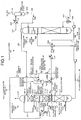
- Fig. 1 is a schematic diagram of a CO 2 recovery system 10A according to a first embodiment of the present invention.
- the same reference numerals are assigned to the same components as these of the CO 2 recovery system shown in Fig. 8 , and explanation thereof is omitted. It is noted that the drawing of the cooling tower 1002 shown in Fig. 8 is omitted.
- the CO 2 recovery system 10A includes the absorption tower 1004 that causes the CO 2 -containing exhaust gas 1001A to come into contact with the CO 2 -absorbing solution 1005 and removes CO 2 , the regeneration tower 1007 that regenerates the rich solution 1006 having absorbed CO 2 by heat exchange, and the separation drum 1026 that condenses steam in the CO 2 gas with the stream released from the regeneration tower 1007 and separates water therefrom.
- the CO 2 recovery system 10A reuses the lean solution (regenerated solution) 1008 in the absorption tower 1004, the lean solution 1008 being produced by removing CO 2 from the rich solution in the regeneration tower 1007.
- the absorption tower 1004 includes the CO 2 -recovery unit 1010 that causes the CO 2 -containing exhaust gas 1001A to come into contact with the CO 2 -absorbing solution 1005 and absorbs CO 2 contained in the CO 2 -containing exhaust gas 1001A, the first washing unit 1013-1 and the second washing unit 1013-2 that are arranged in the upper side of the CO 2 -recovery unit 1010, cool the CO 2 -removed exhaust gas 1001B after CO 2 is removed, and recover the accompanying CO 2 -absorbing solution 1005.
- the absorption tower 1004 also includes the first condensed-water receiver 1015-1 arranged in the lower side of the first washing unit 1013-1 and which collects the condensed water 1014-1 in the first washing unit 1013-1, the second condensed-water receiver 1015-2 arranged in the lower side of the second washing unit 1013-2 and which collects the condensed water 1014-2 in the second washing unit 1013-2, and a filtration membrane apparatus 13 that filters solid content 11 remaining in the lean solution 1008 using a filter 12. Based on the configuration, a low-concentration CO 2 -absorbing solution that circulates in the system is used to clean the filter 12, and the low-concentration CO 2 -absorbing solution used for the cleaning is again returned into the system.
- the CO 2 recovery system also includes a lean-solution branch line 14-1 that supplies the lean solution 1008 to the filtration membrane apparatus 13, and a first cleaning-water supply line 15A that supplies the condensed water 1014-1 collected by the first condensed-water receiver 1015-1 to the lean-solution branch line 14-1.
- the condensed water 1014-1 collected by the first condensed-water receiver 1015-1 is used as the low-concentration CO 2 -absorbing solution, and the condensed water 1014-1 to be supplied to the filtration membrane apparatus 13 is called "cleaning water 16A".
- the solid content 11 remaining in a lean solution 1008A is collected by the filter 12, to enable a supply of a lean solution 1008B produced by removing the solid content 11 from the lean solution 1008A to the lean-solution supply line 1018.
- valves V 11 and V 12 are opened while a valve V 13 is closed. Consequently, the lean solution 1008A which is partially extracted from the lean-solution supply line 1018 is supplied into a body 17 of the filtration membrane apparatus through the lean-solution branch line 14-1 that supplies the lean solution 1008A to the filtration membrane apparatus 13, and the solid content 11 remaining in the lean solution 1008A is collected by the filter 12. Then, the lean solution 1008B without the solid content 11 is supplied to the lean-solution supply line 1018 through a lean-solution branch line 14-2.
- the filtration membrane apparatus 13 uses the cleaning water 16A supplied to the body 17 of the filtration membrane apparatus to collect the CO 2 -absorbing solution 1005 attached to the filter 12 in the cleaning water 16A, and cleans the filter 12.
- the CO 2 recovery system 10A includes the first cleaning-water supply line 15A that supplies the condensed water 1014-1 collected by the first condensed-water receiver 1015-1 to the lean-solution branch line 14-1.
- the condensed water 1014-1 can be supplied to the lean-solution branch line 14-1, and therefore the condensed water 1014-1 can be used as the cleaning water 16A.
- the valve V 11 When the cleaning water 16A is supplied into the body 17 of the filtration membrane apparatus thereby enabling the filter 12 to be cleaned, the valve V 11 is closed while the valves V 12 , V 13 and a valve V 14 are opened. Consequently, it is possible to supply the condensed water 1014-1 as the cleaning water 16A into the filtration membrane apparatus 13, collect the CO 2 -absorbing solution 1005 attached to the filter 12 in the cleaning water 16A, and clean the filter 12.
- the cleaning water 16A used to clean the filter 12 is supplied to the lean-solution supply line 1018 through the lean-solution branch line 14-2.
- the condensed water 1014-1 in the first circulation line L1 contains, for example, about 4 wt.% of the CO 2 -absorbing solution 1005, and the rich solution 1006 in the rich-solution supply line 1017 contains, for example, about 50 wt. % of the CO 2 -absorbing solution 1005.
- the CO 2 -absorbing solution 1005 attached to the filter 12 can be collected by the condensed water 1014-1 and the filter 12 can be cleaned without diluting the CO 2 -absorbing solution 1005 that circulates in the system with water supplied from the outside.
- the water circulating in the system such as the condensed water 1014-1 in the first cleaning-water supply line 15A, is used to clean the filter 12 and is then supplied to the CO 2 -absorbing solution 1005 in the lean-solution supply line 1018. Therefore, the wastewater, after being used to clean the CO 2 -absorbing solution 1005 such as amine attached to the filter 12, is prevented from being discharged to the outside of the system. Consequently, the filter 12 can be cleaned without discharging the CO 2 -absorbing solution 1005 to the outside of the system, thereby preventing a decrease in concentration of the CO 2 -absorbing solution 1005 and greatly reducing loss of the CO 2 -absorbing solution 1005.
- a cartridge filter or a precoat filter is preferably used as the filter 12.
- the present invention is not limited thereto.
- any filter that can filter the solid content 11 in the CO 2 -absorbing solution 1005 is simply required, any filter including a hollow fiber membrane, a sintered metallic filter, and a microfiltration (MF) membrane.
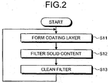
- Fig. 2 is a flowchart of a process for forming a coating layer on a filter and a process for cleaning the filter.
- a coating layer is formed on the filter 12 using the cleaning water 16A as a low-concentration CO 2 -absorbing solution in which a filtering material is dissolved.
- Step S11 a process for forming a coating layer on the surface of the filter 12
- Step S12 a process for filtering the solid content 11 in the CO 2 -absorbing solution 1005 and removing the solid content 11 therefrom
- Step S13 a process for collecting the CO 2 -absorbing solution 1005 attached to the surface of the filter 12 using the cleaning water 16A and cleaning the filter-12
- Step S11 a filtering material that forms the coating layer on the filter 12 is dissolved in the cleaning water 16A, and the cleaning water 16A with the filtering material dissolved therein is applied to the filter 12 to form the coating layer thereon.
- Step S12 the CO 2 -absorbing solution 1005 is supplied to the filtration membrane apparatus 13 through the lean-solution branch line 14-1, and the lean solution 1008A is filtered therein, to collect the solid content 11 remaining in the lean solution 1008A.
- the lean solution 1008B from which the solid content 11 is removed is supplied to the lean-solution supply line 1018.
- the cleaning water 16A is supplied to the filtration membrane apparatus 13, and the CO 2 -absorbing solution 1005 attached to the filter 12 is collected in the cleaning water 16A, to clean the filter 12.
- compressed air is supplied into the body 17 of the filtration membrane apparatus and blows off the filtering material, so that the coating layer is removed.
- the coating layer is formed on the filter 12 and the filter 12 is cleaned, there is no need to supply water into the filtration membrane apparatus 13 from the outside. Therefore, it is possible to form the coating layer on the filter 12, collect the CO 2 -absorbing solution 1005 attached to the filter 12, and clean the filter 12 without diluting the CO 2 -absorbing solution 1005.
- the water circulating in the system can be effectively used in the case of forming the coating layer on the filter inasmuch as in the case of cleaning the filter 12.
- the soot or the like not removed by the cooling tower 1002 or by the desulfurization unit or the like needs to be removed by the absorption tower 1004.
- the amount of collected soot per filter is generally about 100 grams to about 200 grams, which requires replacement of about 50 filters/H.
- the CO 2 recovery system 10A is configured to include the filtration membrane apparatus 13 that collects the CO 2 -absorbing solution 1005 attached to the filter 12 in the condensed water 1014-1 which is a low-concentration CO 2 -absorbing solution 1005 and that cleans the filter 12 at the process for cleaning the filter 12 that filters the solid content 11 remaining in the CO 2 -absorbing solution 1005 such as amine, and to return again the cleaning water 16A used to clean the filter 12 into the system.
- the filtration membrane apparatus 13 that collects the CO 2 -absorbing solution 1005 attached to the filter 12 in the condensed water 1014-1 which is a low-concentration CO 2 -absorbing solution 1005 and that cleans the filter 12 at the process for cleaning the filter 12 that filters the solid content 11 remaining in the CO 2 -absorbing solution 1005 such as amine, and to return again the cleaning water 16A used to clean the filter 12 into the system.
- the filter 12 can be cleaned without discharging the CO 2 -absorbing solution 1005 to the outside of the system, which can prevent the decrease in the concentration of the CO 2 -absorbing solution 1005 and can greatly reduce the loss of the CO 2 -absorbing solution 1005.
- the CO 2 recovery system can be also applied to the coal-fired boiler and a comparatively large amount of solid content in the lean solution can be continuously processed within a short time even if the CO 2 recovery system is upsized and the amount of soot to be removed by the absorption tower 1004 is increased to, for example, 5.0 Kg/H.
- the CO 2 recovery system 10A includes two washing units.
- the present invention is not limited thereto, and thus, one or more than two of washing units may be provided.
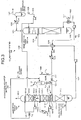
- Fig. 3 is a schematic diagram of a CO 2 recovery system 10B according to the second embodiment.
- the same reference numerals are assigned to the same components as these of the CO 2 recovery system 10A shown in Fig. 1 , and explanation thereof is omitted. It is noted that the drawing of the cooling tower 1002 is omitted.
- the CO 2 recovery system 10B uses the condensed water 1014-2 circulating.in the second circulation line L2 as cleaning water, instead of the condensed water 1014-1 in the CO 2 recovery system 10A.
- the CO 2 recovery system 10B includes a second cleaning-water supply line 15B that supplies the condensed water 1014-2 collected by the second condensed-water receiver 1015-2 to the lean-solution branch line 14-1 through the second circulation line L2 instead of the first cleaning-water supply line 15A in the CO 2 recovery system 10A.
- the condensed water 1014-2 can be supplied to the lean-solution-branch line 14-1, so that the condensed water 1014-2 can be used as cleaning water 16B.
- the valve V 11 is closed while the valves V 12 , V 13 and a valve V 15 are opened. Consequently, it is possible to supply the condensed water 1014-2 as the cleaning water 16B into the filtration membrane apparatus 13, collect the CO 2 -absorbing solution 1005 attached to the filter 12 in the cleaning water 16B, and clean the filter 12.
- the cleaning water 16B used to clean the filter 12 is supplied to the lean-solution supply line 1018 through the lean-solution branch line 14-2.
- the condensed water 1014-2 in the second circulation line L2 contains, for example, about 0.9 wt.% of the CO 2 -absorbing solution 1005, and the rich solution 1006 in the rich-solution supply line 1017 contains, for example, about 50 wt.% of the CO 2 -absorbing solution 1005.
- the CO 2 -absorbing solution 1005 attached to the filter 12 can be collected by the condensed water 1014-2 and the filter 12 can be cleaned without diluting the CO 2 -absorbing solution 1005 that circulates in the system with the water supplied from the outside.
- the water circulating in the system such as the condensed water 1014-2 in the second cleaning-water supply line 15B, is used to clean the filter 12 and is supplied to the CO 2 -absorbing solution 1005 in the lean-solution supply line 1018. Therefore, the wastewater, after being used to clean the CO 2 -absorbing solution 1005 such as amine attached to the filter 12, is prevented from being discharged to the outside of the system. Consequently, the filter 12 can be cleaned without discharging the CO 2 -absorbing solution 1005 to the outside of the system.
- the condensed water 1014-2 is supplied as the cleaning water 16B into the body 17 of the filtration membrane apparatus and the filter 12 is thereby cleaned, so that the CO 2 -absorbing solution 1005 attached to the surface of the filter 12 can be collected in the cleaning water 16B and the filter 12 can be cleaned without diluting the CO 2 -absorbing solution 1005 that circulates in the system with the water supplied from the outside.
- the filter 12 can be cleaned without discharging the CO 2 -absorbing solution 1005 to the outside of the system, thereby preventing the concentration of the CO 2 -absorbing solution 1005 from decreasing and greatly reducing the loss of the CO 2 -absorbing solution 1005.
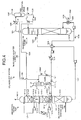
- Fig. 4 is a schematic diagram of a CO 2 recovery system 10C according to the third embodiment.
- the same reference numerals are assigned to the same components as these of the CO 2 recovery system 10A shown in Fig. 1 , and explanation thereof is omitted. It is noted that the drawing of the cooling tower 1002 is omitted.
- the CO 2 recovery system 10C uses the water 1028 that is discharged from the regeneration tower 1007 and is separated by the separation drum 1026 as cleaning water, instead of the condensed water 1014-1 used in the CO 2 recovery system 10A.
- the CO 2 recovery system 10C includes a third cleaning-water supply line 15C that supplies the separated water 1028 to the lean-solution branch line 14-1, instead of the first cleaning-water supply line 15A in the CO 2 recovery system 10A.
- the water 1028 can be supplied to the lean-solution branch line 14-1, so that the water 1028 can be used as cleaning water 16C.
- the valve V 11 is closed while the valves V 12 , V 13 and a valve V 16 are opened. Consequently, it is possible to supply the water 1028 as the cleaning water 16C into the filtration membrane apparatus 13, collect the CO 2 -absorbing solution 1005 attached to the filter 12 in the cleaning water 16C, and clean the filter 12.
- the cleaning water 16C used to clean the filter 12 is supplied to the lean-solution supply line 1018 through the lean-solution branch line 14-2.
- the water 1028 in the water circulation line 1029 contains, for example, about 0.5 wt.% of the CO 2 -absorbing solution 1005, and the rich solution 1006 in the rich-solution supply line 1017 contains, for example, about 50 wt.% of the CO 2 -absorbing solution 1005.
- the CO 2 -absorbing solution 1005 attached to the filter 12 can be collected by the water 1028 and the filter 12 can be cleaned without diluting the CO 2 -absorbing solution 1005 that circulates in the system with the water supplied from the outside.
- the water circulating in the system such as the water 1028 that contains the CO 2 -absorbing solution 1005 in the water circulation line 1029, is used to clean the filter 12, and is supplied to the CO 2 -absorbing solution 1005 in the lean-solution supply line 1018. Therefore, the wastewater, after being used to clean the CO 2 -absorbing solution 1005 such as amine attached to the filter 12, is prevented from being discharged to the outside of the system. Consequently, the filter 12 can be cleaned without discharging the CO 2 -absorbing solution 1005 to the outside of the system.
- the water 1028 is supplied as the cleaning water 16C into the body 17 of the filtration membrane apparatus and the filter 12 is thereby cleaned, so that the CO 2 -absorbing solution 1005 attached to the surface of the filter 12 can be collected in the cleaning water 16C and the filter 12 can be cleaned without diluting the CO 2 -absorbing solution 1005 that circulates in the system with the water supplied from the outside.
- the filter 12 can be cleaned without discharging the CO 2 -absorbing solution 1005 to the outside of the system, thereby preventing the decrease in the concentration of the CO 2 -absorbing solution 1005 and greatly reducing the loss of the CO 2 -absorbing solution 1005.
- Fig. 5 is a schematic diagram of a CO 2 recovery system 10D according to the fourth embodiment.
- the same reference numerals are assigned to the same components as these of the CO 2 recovery system 10A shown in Fig. 1 and these of the CO 2 recovery system 10B shown in Fig. 3 , and explanation thereof is.omitted. It is noted that the drawing of the cooling tower 1002 is omitted.
- the CO 2 recovery system 10D uses the condensed water 1014-2 being as cleaning water in the CO 2 recovery system 10B shown in Fig. 3 to clean the filter 12, and supplies the condensed water 1014-2, after using it for the cleaning, to the first circulation line L1 instead of the lean-solution supply line 1018.
- the CO 2 recovery system 10D includes a first cleaning-water return line 18A that supplies the cleaning water 16B after cleaning the filter 12 in the filtration membrane apparatus 13 to the first circulation line L1, instead of the lean-solution branch line 14-2 in the CO 2 recovery system 10B shown in Fig. 3 .
- the cleaning water 16B after cleaning the filter 12 can be supplied to the first circulation line L1, so that the cleaning water 16B can be mixed with the condensed water 1014-1, and thus the mixed water can be used to recover the CO 2 -absorbing solution 1005 accompanying the CO 2 -removed exhaust gas 1001B in the first washing unit 1013-1.
- the valves V 11 and V 12 are closed while the valves V 13 , V 15 and a valve V 17 are opened. Consequently, it is possible to supply the condensed water 1014-2 as the cleaning water 16B into the filtration membrane apparatus 13, collect the CO 2 -absorbing solution 1005 attached to the filter 12 in the cleaning water 16B, and clean the filter 12.
- the cleaning water 16B used to clean the filter 12 is supplied to the first circulation line L1 through the first cleaning-water return line 18A.
- the condensed water 1014-2 in the second circulation line L2 contains, for example, about 0.8 wt.% of the CO 2 -absorbing solution 1005, and the condensed water 1014-1 in the first circulation line L1 contains, for example, about 4.0 wt.% of the CO 2 -absorbing solution 1005.
- the CO 2 -absorbing solution 1005 attached to the filter 12 can be collected by the condensed water 1014-2 and the filter 12 can be cleaned without diluting the CO 2 -absorbing solution 1005 with the water supplied from the outside.
- the condensed water 1014-2 in the second cleaning-water supply line 15B is used to clean the filter 12, the wastewater, after being used to clean the CO 2 -absorbing solution 1005 attached to the filter 12, is prevented from being discharged to the outside of the system. Therefore, the filter 12 can be cleaned without discharging the CO 2- absorbing solution 1005 to the outside of the system.
- the condensed water 1014-2 is supplied as the cleaning water 16B into the body 17 of the filtration membrane apparatus and the filter 12 is thereby cleaned, so that the CO 2 -absorbing solution 1005 attached to the surface of the filter 12 can be collected in the cleaning water 16B and the filter 12 can be cleaned without diluting the CO 2 -absorbing solution 1005 that circulates in the system with the water supplied from the outside.
- the filter 12 can be cleaned without discharging the CO 2 -absorbing solution 1005 to the outside of the system, thereby preventing the concentration of the CO 2 -absorbing solution 1005 from decreasing, and greatly reducing the loss of the CO 2 -absorbing solution 1005.
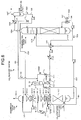
- Fig. 6 is a schematic diagram of a CO 2 recovery system 10E according to the fifth embodiment.
- the same reference numerals are assigned to the same components as these of the CO 2 recovery system 10A shown in Fig. 1 , these of the CO 2 recovery system 10C shown in Fig. 4 , and these of the CO 2 recovery system 10D shown in Fig. 5 , and explanation thereof is omitted. It is noted that the drawing of the cooling tower 1002 is omitted.
- the CO 2 recovery system 10E uses the water 1028 being cleaning water in the CO 2 recovery system 10C shown in Fig. 4 to clean the filter 12, and then supplies the water 1028 used for the cleaning to the first circulation line L1 instead of the lean-solution supply line 1018.
- the CO 2 recovery system 10E includes the first cleaning-water return line 18A that supplies the cleaning water 16C after cleaning the filter 12 in the filtration membrane apparatus 13 to the first circulation line L1, instead of the lean-solution branch line 14-2 in the CO 2 recovery system 10C.
- the valves V 11 and V 12 are closed while the valves V 13 , V 16 , and V 17 are opened. Consequently, it is possible to supply the water 1028 as the cleaning water 16C into the filtration membrane apparatus 13, collect the CO 2 -absorbing solution 1005 attached to the filter 12 in the cleaning water 16C, and clean the filter 12.
- the cleaning water 16C used to clean the filter 12 is supplied to the first circulation line L1 through the first cleaning-water return line 18A.
- the water 1028 in the water circulation line 1029 contains, for example, about 0.5 wt.% of the CO 2 -absorbing solution 1005, and the condensed water 1014-1 in the first circulation line L1 contains, for example, about 4.0 wt.% of the CO 2 -absorbing solution 1005.
- the filter 12 can be cleaned without discharging the CO 2 -absorbing solution 1005 to the outside of the system.
- the water 1028 is supplied as the cleaning water 16C into the body 17 of the filtration membrane apparatus and the filter 12 is thereby cleaned, making it possible to collect the CO 2 -absorbing solution 1005 attached to the surface of the filter 12 in the cleaning water 16C and clean the filter 12 without diluting the CO 2 -absorbing solution 1005 that circulates in the system with the water supplied from the outside.
- the filter 12 can be cleaned without discharging the CO 2 -absorbing solution 1005 to the outside of the system, thereby preventing the concentration of the CO 2 -absorbing solution 1005 from decreasing, greatly reducing the loss of the CO 2 -absorbing solution 1005.
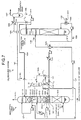
- Fig. 7 is a schematic diagram of a CO 2 recovery system 10F according to the sixth embodiment.
- the same reference numerals are assigned to the same components as these of the CO 2 recovery system 10A shown in Fig. 1 and these of the CO 2 recovery system 10C shown in Fig. 4 , and explanation thereof is omitted. It is noted that the drawing of the cooling tower 1002 is omitted.
- the CO 2 recovery system 10F uses the water 1028 being cleaning water in the CO 2 recovery system 10C shown in Fig. 4 to clean the filter 12, and then supplies the water 1028 after being used for the cleaning, to the second circulation line L2 instead of the lean-solution supply line 1018.
- the CO 2 recovery system 10F includes a second cleaning-water return line 18B that supplies the cleaning water 16C after cleaning the filter 12 in the filtration membrane apparatus 13 to the second circulation line L2, instead of the first cleaning-water return line 18A in the CO 2 recovery system 10E shown in Fig. 6 .
- the cleaning water 16C after cleaning the filter 12 can be supplied to the second circulation line L2, so that the cleaning water 16C can be mixed with the condensed water 1014-2, and thus the mixed water can be used to recover the CO 2 -absorbing solution 1005 accompanying the CO 2 -removed exhaust gas 1001B in the second washing unit 1013-2.
- the valves V 11 and V 12 are closed while the valves V 13 , V 16 and a valve V 18 are opened. Consequently, it is possible to supply the water 1028 as the cleaning water 16C into the filtration membrane apparatus 13, collect the CO 2 -absorbing solution 1005 attached to the filter 12 in the cleaning water 16C, and clean the filter 12.
- the cleaning water 16C used to clean the filter 12 is supplied to the second circulation line L2 through the second cleaning-water return line 18B.
- the water 1028 in the water circulation line 1029 contains, for example, about 0.5 wt.% of the CO 2 -absorbing solution 1005, and the condensed water 1014-2 in the second circulation line L2 contains, for example, about 0.8 wt.% of the CO 2 -absorbing solution 1005.
- the filter 12 can be cleaned without discharging the CO 2 -absorbing solution 1005 to the outside of the system.
- the water 1028 is supplied as the cleaning water 16C into the body 17 of the filtration membrane apparatus and the filter 12 is thereby cleaned, so that the CO 2 -absorbing solution 1005 attached to the surface of the filter 12 can be collected in the cleaning water 16C and the filter 12 can be cleaned without diluting the CO 2 -absorbing solution 1005 that circulates in the system with the water supplied from the outside.
- the filter 12 can be cleaned without discharging the CO 2 -absorbing solution 1005 to the outside of the system, thereby preventing the concentration of the CO 2 -absorbing solution 1005 from decreasing and greatly reducing the loss of the CO 2 -absorbing solution 1005.
- the method of removing the solid content 11 attached to the filter 12 is explained using the cleaning waters 16A to 16C.
- the present invention is not limited thereto.
- a solution can simply be supplied from a low concentration to a high concentration of the CO 2 -absorbing solution 1005 in the solution, or a solution in any line in which other CO 2 -absorbing solution 1005 circulates may be used.
- the present invention is configured to remove the solid content 11 remaining in the lean solution 1008A which is partially removed from the lean-solution supply line 1018.
- the present invention may also be configured to partially remove solutions from both the lean solution 1008 and the rich solution 1006, to remove the solid contents 11 remaining in the both solutions.
- the CO 2 recovery system includes the filtration membrane apparatus that collects the CO 2 -absorbing solution attached to the filter in the low-concentration CO 2 -absorbing solution when the solid content remaining in the CO 2 -absorbing solution is filtered by the filter and that cleans the filter, and the cleaning water used to clean the filter is again returned into the system. Therefore, there is no need to supply water from the outside into the system upon replacement of the filter, and thus, the CO 2 -absorbing solution attached to the filter can be collected in the cleaning water and the filter can be cleaned without diluting the CO 2 -absorbing solution that circulates in the system with the water supplied from the outside. Moreover, the filter can be cleaned without discharging the CO 2 -absorbing solution to the outside of the system, thereby preventing the concentration of the CO 2 -absorbing solution from decreasing and greatly reducing the loss of the CO 2 -absorbing solution.
- the present invention can be also applied to the coal-fired boiler and can continuously process a large amount of solid content in the lean solution even if a great deal of soot is to be removed in the absorption tower.
Landscapes
- Chemical & Material Sciences (AREA)
- Engineering & Computer Science (AREA)
- Chemical Kinetics & Catalysis (AREA)
- Water Supply & Treatment (AREA)
- Analytical Chemistry (AREA)
- General Chemical & Material Sciences (AREA)
- Oil, Petroleum & Natural Gas (AREA)
- Treating Waste Gases (AREA)
- Gas Separation By Absorption (AREA)
- Separation Using Semi-Permeable Membranes (AREA)
- Carbon And Carbon Compounds (AREA)
Claims (7)
- CO2-Rückgewinnungssystem, umfassend:einen Absorptionsturm (1004), der veranlasst, dass CO2-haltiges Abgas mit einer CO2-absorbierenden Lösung in Kontakt kommt und CO2 entfernt,einen Regenerierungsturm (1007), der eine angereicherte Lösung, die CO2 absorbiert hat, durch Wärmetausch regeneriert,eine Trenntrommel (1026), die aus dem Regenerierungsturm (1007) freigesetzten Dampf zu CO2-Gas kondensiert und Wasser abscheidet, wobei eine abgereicherte Lösung, die durch Entfernen von CO2 aus der angereicherten Lösung entstanden ist, in dem Absorptionsturm (1004) wiederverwendet wird,eine Zuleitung für angereicherte Lösung (1017), die die angereicherte Lösung in den Regenerierungsturm (1007) leitet, undeine Zuleitung für abgereicherte Lösung (1018), die die abgereicherte Lösung in den Absorptionsturm (1004) leitet,wobei der Absorptionsturm (1004) enthält:eine CO2-Rückgewinnungseinheit (1010), die veranlasst, dass das CO2-haltige Abgas mit der CO2-absorbierenden Lösung in Kontakt kommt und in dem Abgas enthaltenes CO2 absorbiert,mindestens eine Wascheinheit (1013-1, 1013-2), die in einer Oberseite der CO2-Rückgewinnungseinheit (1010) angeordnet ist, CO2-befreites Abgas kühlt, nachdem das CO2 entfernt wurde, und die CO2-absorbierende Lösung, die das CO2-befreite Abgas begleitet, zurückgewinnt, undeinen Kondenswasserfänger (1015-1, 1015-2), der in einer Unterseite der Wascheinheit (1013-1, 1013-2) angeordnet ist und Kondenswasser in jeder Wascheinheit (1013-1, 1013-2) auffängt,wobei das CO2-Rückgewinnungssystem dadurch gekennzeichnet ist, dass der Absorptionsturm des Weiteren eine Filtrationsmembranvorrichtung (13) umfasst, die in der abgereicherten Lösung verbliebene Feststoffe mittels eines Filters (12) filtert, wobei die Filtrationsmembranvorrichtung (13) zwischen einer Abzweigleitung für abgereicherte Lösung (14-1), die die zu filternde abgereicherte Lösung zu der Filtrationsmembranvorrichtung (13) leitet, einer Zuleitung für Reinigungswasser (15A),die die niedrig-konzentrierte CO2-absorbierende Lösung zu der Abzweigleitung für abgereicherte Lösung (14-1) leitet, und einer Abzweigleitung für abgereicherte Lösung (14-2), die eine abgereicherte Lösung ohne die Feststoffe zu der Zuleitung für abgereicherte Lösung (1018) leitet, angeordnet ist, unddadurch, dasseine niedrig-konzentrierte CO2-absorbierende Lösung, die in dem System zirkuliert, verwendet wird, um den Filter (12) zu reinigen, und die zum Reinigen verwendete niedrig-konzentrierte CO2-absorbierende Lösung erneut in das System zurückgeleitet wird.
- CO2-Rückgewinnungssystem nach Anspruch 1, wobei das aufgefangene Kondenswasser und/oder das abgeschiedene Wasser aus niedrig-konzentrierten CO2-absorbierenden Lösungen als Reinigungswasser verwendet werden.
- CO2-Rückgewinnungssystem nach einem der Ansprüche 1 bis 2, ferner umfassend eine Reinigungswasser-Rücklaufleitung (18A), die die niedrig-konzentrierte CO2-absorbierende Lösung, die zum Reinigen des Filters (12) verwendet wird, zu dem Kondenswasserfänger (1015-1, 1015-2) leitet.
- CO2-Rückgewinnungssystem nach einem der Ansprüche 1 bis 3, wobei die CO2-absorbierende Lösung eine absorbierende Lösung auf Aminbasis ist.
- Verfahren zum Reinigen einer Filtrationsmembranvorrichtung (13) unter Verwendung eines CO2-Rückgewinnungssystems nach einem der Ansprüche 1 bis 4, dadurch gekennzeichnet, dass es folgende Schritte enthält:Veranlassen, dass CO2-haltiges Abgas in Kontakt mit einer CO2-absorbierenden Lösung kommt,Entfernen von CO2 in einer CO2-Rückgewinnungseinheit (1010) eines Absorptionsturms (1004),Regenerieren einer angereicherten Lösung, die CO2 absorbiert hat, in einem Regenerierungsturm (1007),Filtern von Feststoffen, die in einer abgereicherten Lösung verblieben sind, die durch Entfernen von regeneriertem CO2 aus der angereicherten Lösung entstanden ist, durch einen Filter (12), der in der Filtrationsmembranvorrichtung (13) angeordnet ist,Zuführen einer niedrig-konzentrierten CO2-absorbierenden Lösung, die von dem ersten Kondenswasserfänger (1015-1) kommend aufgefangen wurde, zu der Filtrationsmembranvorrichtung (13),Reinigen des Filters (12) unter Verwendung der niedrig-konzentrierten CO2-absorbierenden Lösung, underneutes Rückführen der niedrig-konzentrierten CO2-absorbierenden Lösung, die zum Reinigen des Filters (12) verwendet wurde, zu der CO2-Rückgewinnungseinheit (1010).
- Verfahren nach Anspruch 5, wobei das aufgefangene Kondenswasser und/oder das abgeschiedene Wasser aus niedrig-konzentrierten CO2-absorbierenden Lösungen als Reinigungswasser verwendet werden.
- Verfahren nach Anspruch 5 oder 6, wobei die CO2-absorbierende Lösung eine absorbierende Lösung auf Aminbasis ist.
Applications Claiming Priority (1)
| Application Number | Priority Date | Filing Date | Title |
|---|---|---|---|
| JP2008022649A JP5072627B2 (ja) | 2008-02-01 | 2008-02-01 | Co2回収装置及びろ過膜装置の洗浄方法 |
Publications (2)
| Publication Number | Publication Date |
|---|---|
| EP2085133A1 EP2085133A1 (de) | 2009-08-05 |
| EP2085133B1 true EP2085133B1 (de) | 2016-03-16 |
Family
ID=39951605
Family Applications (1)
| Application Number | Title | Priority Date | Filing Date |
|---|---|---|---|
| EP08163306.7A Active EP2085133B1 (de) | 2008-02-01 | 2008-08-29 | Co2-rückgewinnungssystem mit filtrationsvorrichtung und verfahren zum reinigen der filtrationsvorrichtung |
Country Status (6)
| Country | Link |
|---|---|
| US (1) | US7938889B2 (de) |
| EP (1) | EP2085133B1 (de) |
| JP (1) | JP5072627B2 (de) |
| AU (1) | AU2008207562B8 (de) |
| CA (1) | CA2639168C (de) |
| RU (1) | RU2390371C1 (de) |
Families Citing this family (42)
| Publication number | Priority date | Publication date | Assignee | Title |
|---|---|---|---|---|
| US8192530B2 (en) | 2007-12-13 | 2012-06-05 | Alstom Technology Ltd | System and method for regeneration of an absorbent solution |
| JP4881412B2 (ja) | 2009-09-10 | 2012-02-22 | 株式会社東芝 | 二酸化炭素回収装置 |
| JP5351728B2 (ja) | 2009-12-03 | 2013-11-27 | 三菱重工業株式会社 | Co2回収装置およびco2回収方法 |
| JP5371734B2 (ja) * | 2009-12-25 | 2013-12-18 | 三菱重工業株式会社 | Co2回収装置およびco2回収方法 |
| US9314734B2 (en) * | 2010-01-14 | 2016-04-19 | Alstom Technology Ltd | Wash water method and system for a carbon dioxide capture process |
| JP5638262B2 (ja) * | 2010-02-23 | 2014-12-10 | 三菱重工業株式会社 | Co2回収装置およびco2回収方法 |
| US8425655B2 (en) | 2010-07-09 | 2013-04-23 | Carbon Capture Scientific, Llc | Gas pressurized separation column and process to generate a high pressure product gas |
| US9919259B2 (en) | 2010-07-09 | 2018-03-20 | Carbon Capture Scientific, Llc | Gas pressurized separation column and process to generate a high pressure product gas |
| EP2433700A1 (de) * | 2010-09-23 | 2012-03-28 | Alstom Technology Ltd | Spurenkomponentenentfernung in CO2-Entfernungsverfahren mithilfe einer semipermeablen Membran |
| WO2012070523A1 (ja) * | 2010-11-22 | 2012-05-31 | バブコック日立株式会社 | 燃焼排ガス中の二酸化炭素除去装置 |
| JP5737916B2 (ja) * | 2010-12-01 | 2015-06-17 | 三菱重工業株式会社 | Co2回収システム |
| US9133407B2 (en) | 2011-02-25 | 2015-09-15 | Alstom Technology Ltd | Systems and processes for removing volatile degradation products produced in gas purification |
| CN102133499A (zh) * | 2011-03-03 | 2011-07-27 | 杨东 | 一种烟气中酸性气体捕集系统和方法 |
| FR2980374A1 (fr) * | 2011-09-22 | 2013-03-29 | IFP Energies Nouvelles | Procede de captage de dioxyde de carbone, avec section de lavage acide optimisee |
| US8864878B2 (en) | 2011-09-23 | 2014-10-21 | Alstom Technology Ltd | Heat integration of a cement manufacturing plant with an absorption based carbon dioxide capture process |
| KR101315709B1 (ko) * | 2011-11-01 | 2013-10-10 | 기아자동차주식회사 | 이산화탄소 포집 설비 |
| KR101382705B1 (ko) * | 2011-11-03 | 2014-04-09 | 기아자동차주식회사 | 배기가스 내 이산화탄소 회수장치 |
| KR101382863B1 (ko) * | 2011-11-03 | 2014-04-09 | 현대자동차주식회사 | 배기가스 내 이산화탄소 회수장치 |
| KR101704057B1 (ko) * | 2011-11-21 | 2017-02-08 | 현대자동차주식회사 | 배기가스 내 이산화탄소 회수장치 |
| KR101704058B1 (ko) * | 2011-11-21 | 2017-02-08 | 현대자동차주식회사 | 배기가스 내 이산화탄소 회수장치 |
| CN104105537A (zh) * | 2011-11-29 | 2014-10-15 | 苏舍化学技术有限公司 | 吸收二氧化碳的方法和设备 |
| JP5117612B2 (ja) * | 2011-11-30 | 2013-01-16 | 株式会社東芝 | 二酸化炭素回収装置 |
| EP2786793B1 (de) * | 2011-12-01 | 2017-10-18 | Kabushiki Kaisha Toshiba, Inc. | Vorrichtung zur rückgewinnung von kohlendioxid, kohlendioxidrückgewinnungsverfahren und verfahren zur rückgewinnung einer aminverbindung |
| US8911538B2 (en) | 2011-12-22 | 2014-12-16 | Alstom Technology Ltd | Method and system for treating an effluent stream generated by a carbon capture system |
| US9028654B2 (en) | 2012-02-29 | 2015-05-12 | Alstom Technology Ltd | Method of treatment of amine waste water and a system for accomplishing the same |
| JP5959882B2 (ja) * | 2012-03-05 | 2016-08-02 | 三菱日立パワーシステムズ株式会社 | 燃焼排ガス中の二酸化炭素化学吸収システム |
| WO2014065477A1 (ko) * | 2012-10-26 | 2014-05-01 | 재단법인 포항산업과학연구원 | 이산화탄소 포집 공정에 있어서 흡수제의 휘발이 억제된 이산화탄소 포집장치 |
| US9101912B2 (en) | 2012-11-05 | 2015-08-11 | Alstom Technology Ltd | Method for regeneration of solid amine CO2 capture beds |
| DE102012111185A1 (de) * | 2012-11-20 | 2014-05-22 | Thyssenkrupp Uhde Gmbh | Apparat zur Gaswäsche |
| US9623366B2 (en) * | 2013-03-04 | 2017-04-18 | Mitsubishi Heavy Industries, Ltd. | CO2 recovery system and CO2 recovery method |
| US8888895B1 (en) * | 2013-09-10 | 2014-11-18 | U.S. Department Of Energy | Method of CO2 removal from a gasesous stream at reduced temperature |
| US20150157963A1 (en) * | 2013-12-10 | 2015-06-11 | General Electric Company | Filter assembly for use in a natural gas liquefaction system and method of operating the same |
| JP2015134334A (ja) | 2014-01-17 | 2015-07-27 | 三菱重工業株式会社 | リクレーミング装置及び方法、co2又はh2s又はその双方の回収装置 |
| JP6216259B2 (ja) * | 2014-02-05 | 2017-10-18 | 三菱重工業株式会社 | Co2回収装置及びco2回収装置のろ過膜装置の洗浄方法 |
| JP6770453B2 (ja) * | 2017-02-01 | 2020-10-14 | 三菱重工エンジニアリング株式会社 | 排ガス処理システム |
| JP6882076B2 (ja) * | 2017-05-30 | 2021-06-02 | 株式会社東芝 | 二酸化炭素回収システムおよび二酸化炭素回収方法 |
| WO2019178354A1 (en) * | 2018-03-14 | 2019-09-19 | Gas Technology Institute | Membrane absorption process for co2 capture |
| CN111871159A (zh) * | 2020-07-15 | 2020-11-03 | 中石化南京化工研究院有限公司 | 一种膜分离耦合醇胺溶液捕集烟气co2装置和方法 |
| US11905241B2 (en) * | 2020-12-22 | 2024-02-20 | Kellogg Brown & Root Llc | Recovery of light olefins from dry hydrocarbon gas from refinery and petrochemical production processes for production of alkylate |
| JP7524086B2 (ja) * | 2021-01-15 | 2024-07-29 | 株式会社東芝 | 二酸化炭素回収システムおよび二酸化炭素回収システムの運転方法 |
| US20230302397A1 (en) * | 2022-03-24 | 2023-09-28 | University Of Kentucky Research Foundation | Dual-Loop Solution-Based Carbon Capture System and Method |
| CN115285994B (zh) * | 2022-08-12 | 2023-07-25 | 青岛大学 | 一种高效低能耗船舶co2捕集-膜解吸-矿化固定系统及方法 |
Family Cites Families (33)
| Publication number | Priority date | Publication date | Assignee | Title |
|---|---|---|---|---|
| US2970177A (en) * | 1956-11-06 | 1961-01-31 | Phillips Petroleum Co | Olefin recovery process |
| US3339342A (en) * | 1965-03-15 | 1967-09-05 | Du Pont | Process for removing h2s and co2 from gas mixtures |
| US3435590A (en) * | 1967-09-01 | 1969-04-01 | Chevron Res | Co2 and h2s removal |
| US3687630A (en) * | 1968-07-24 | 1972-08-29 | John P Tailor | Gas cleaning process |
| DE1801539C2 (de) * | 1968-10-05 | 1983-04-07 | Metallgesellschaft Ag, 6000 Frankfurt | Verfahren zum Reinigen technischer Gase durch Absorption der darin enthaltenen Verunreinigungen unter Druck in einem hochsiedenden, mit Wasser mischbaren organischen Lösungsmittel |
| SU481296A1 (ru) | 1972-10-26 | 1975-08-25 | Предприятие П/Я Р-6603 | Способ очистки газов от кислых компонентов |
| US4079117A (en) * | 1975-08-11 | 1978-03-14 | Union Carbide Corporation | Process for acid gas removal |
| US4292286A (en) | 1978-12-22 | 1981-09-29 | Exxon Research & Engineering Co. | Process for selective removal of cyclic urea from hindered amine gas treating solution |
| US4341746A (en) * | 1981-06-01 | 1982-07-27 | Exxon Research & Engineering Co. | Removal of degradation product from gas treating solution |
| US4624839A (en) * | 1983-12-12 | 1986-11-25 | The Dow Chemical Company | Process for the recovery of CO2 from flue gases |
| US4798910A (en) * | 1985-01-29 | 1989-01-17 | Herrin J Pearman | Process sequencing for amine regeneration |
| US4973404A (en) * | 1989-09-05 | 1990-11-27 | Aurian Corporation | Micro/ultra filtration system |
| JP3237113B2 (ja) * | 1989-11-06 | 2001-12-10 | 栗田工業株式会社 | ガス吸収液の処理方法 |
| JPH0411921A (ja) * | 1990-05-01 | 1992-01-16 | Idemitsu Eng Co Ltd | 精製用吸着液の劣化物除去方法 |
| JPH0699026A (ja) | 1991-02-12 | 1994-04-12 | Mitsubishi Heavy Ind Ltd | 排ガスの処理方法 |
| JPH06285329A (ja) * | 1991-10-04 | 1994-10-11 | Chubu Electric Power Co Inc | 排煙脱硫装置の排水の処理設備 |
| JP3504674B2 (ja) | 1992-03-03 | 2004-03-08 | 関西電力株式会社 | 燃焼排ガス中の二酸化炭素と硫黄酸化物を除去する方法 |
| US6174507B1 (en) * | 1998-06-05 | 2001-01-16 | Texaco Inc. | Acid gas solvent filtration system |
| US6592829B2 (en) | 1999-06-10 | 2003-07-15 | Praxair Technology, Inc. | Carbon dioxide recovery plant |
| US6165433A (en) * | 1999-06-10 | 2000-12-26 | Praxair Technology, Inc. | Carbon dioxide recovery with composite amine blends |
| US6312503B1 (en) * | 1999-10-13 | 2001-11-06 | Arteva North America S.A.R.L. | System to quench gasses and remove condensables |
| US6267889B1 (en) * | 2000-01-26 | 2001-07-31 | Mdf, Llc | Rotary drum filter |
| NL1015827C2 (nl) | 2000-07-27 | 2002-02-01 | Continental Engineering B V | Winning van zuiver CO2 uit rookgassen. |
| AUPR692401A0 (en) * | 2001-08-09 | 2001-08-30 | U.S. Filter Wastewater Group, Inc. | Method of cleaning membrane modules |
| JP4345525B2 (ja) | 2004-03-05 | 2009-10-14 | 井関農機株式会社 | 苗移植機 |
| RU2252063C1 (ru) | 2004-06-28 | 2005-05-20 | Закрытое Акционерное Общество Научно-Производственная Компания "Интергаз" | Способ очистки газовых смесей от диоксида углерода (варианты) и устройство для очистки газовых смесей от диоксида углерода (варианты) |
| CA2499656A1 (en) * | 2005-03-03 | 2006-09-03 | Udo Staschik | Method and portable apparatus for in-transport treatment of waste |
| EP1726353A1 (de) * | 2005-05-25 | 2006-11-29 | Johnson Diversey, Inc. | Membranfiltration eines Produktes |
| US7846407B2 (en) * | 2006-04-07 | 2010-12-07 | Liang Hu | Self-concentrating absorbent for acid gas separation |
| JP5232361B2 (ja) * | 2006-04-13 | 2013-07-10 | 三菱重工業株式会社 | Co2回収装置及びco2回収方法 |
| EP2117683B1 (de) * | 2006-12-15 | 2013-02-27 | Sinvent AS | Verfahren zum abfangen von co2 aus abgas |
| JP4795991B2 (ja) * | 2007-02-27 | 2011-10-19 | 三菱重工業株式会社 | Co2回収装置及びco2回収装置における固形分取出し方法 |
| US8425734B2 (en) * | 2007-07-02 | 2013-04-23 | I3 Nanotec Llc | Membrane-based hybrid process for separation of mixtures of organics, solids, and water |
-
2008
- 2008-02-01 JP JP2008022649A patent/JP5072627B2/ja active Active
- 2008-08-27 AU AU2008207562A patent/AU2008207562B8/en active Active
- 2008-08-28 US US12/200,277 patent/US7938889B2/en active Active
- 2008-08-28 CA CA2639168A patent/CA2639168C/en active Active
- 2008-08-29 EP EP08163306.7A patent/EP2085133B1/de active Active
- 2008-08-29 RU RU2008135261/15A patent/RU2390371C1/ru active
Also Published As
| Publication number | Publication date |
|---|---|
| JP2009179546A (ja) | 2009-08-13 |
| JP5072627B2 (ja) | 2012-11-14 |
| RU2008135261A (ru) | 2010-03-10 |
| CA2639168A1 (en) | 2009-08-01 |
| AU2008207562B8 (en) | 2011-03-17 |
| US20090193970A1 (en) | 2009-08-06 |
| AU2008207562A1 (en) | 2009-08-20 |
| CA2639168C (en) | 2012-03-27 |
| US7938889B2 (en) | 2011-05-10 |
| EP2085133A1 (de) | 2009-08-05 |
| RU2390371C1 (ru) | 2010-05-27 |
| AU2008207562B2 (en) | 2010-10-07 |
Similar Documents
| Publication | Publication Date | Title |
|---|---|---|
| CA2639168C (en) | Co2 recovery system and method of cleaning filtration membrane apparatus | |
| US8016919B2 (en) | CO2 recovery system and solid-particles removing method for use in the same | |
| JP5507584B2 (ja) | アミン放出物制御のための方法およびプラント | |
| EP2990095B1 (de) | Co2-rückgewinnungsvorrichtung und verfahren zur reinigung einer filtrationsmembranvorrichtung einer co2-rückgewinnungsvorrichtung | |
| JP6101783B2 (ja) | Co2回収システム及びco2回収方法 | |
| US7641717B2 (en) | Ultra cleaning of combustion gas including the removal of CO2 | |
| JP6072055B2 (ja) | 排ガス処理システム及び方法 | |
| EP2829311B1 (de) | Ammoniakstripper für ein Kohlenstoffabscheidungssystem zur Reduzierung des Energieverbrauchs | |
| JP6016513B2 (ja) | Co2回収装置およびco2回収方法 | |
| CN101716458A (zh) | 燃煤电厂烟气中二氧化碳捕集系统及处理方法 | |
| JP2013059726A (ja) | Co2回収装置およびco2回収方法 | |
| JP5931834B2 (ja) | リクレーミング装置及び方法、co2又はh2s又はその双方の回収装置 | |
| JP2015134334A (ja) | リクレーミング装置及び方法、co2又はh2s又はその双方の回収装置 | |
| JP4831834B2 (ja) | Co2回収装置及びco2吸収液回収方法 | |
| US8986640B1 (en) | System and method for recovering ammonia from a chilled ammonia process | |
| JP2013173106A (ja) | 排ガス中の水銀回収方法及び回収装置 | |
| KR101397068B1 (ko) | 농축수 재이용이 가능한 배기가스의 폐열회수 및 백연저감 장치 | |
| KR102213331B1 (ko) | 탈취공정과 연계된 고순도 이산탄소 포집 공정 및 장치 |
Legal Events
| Date | Code | Title | Description |
|---|---|---|---|
| PUAI | Public reference made under article 153(3) epc to a published international application that has entered the european phase |
Free format text: ORIGINAL CODE: 0009012 |
|
| AK | Designated contracting states |
Kind code of ref document: A1 Designated state(s): AT BE BG CH CY CZ DE DK EE ES FI FR GB GR HR HU IE IS IT LI LT LU LV MC MT NL NO PL PT RO SE SI SK TR |
|
| AX | Request for extension of the european patent |
Extension state: AL BA MK RS |
|
| 17P | Request for examination filed |
Effective date: 20100129 |
|
| AKX | Designation fees paid |
Designated state(s): DE FR GB IT |
|
| 17Q | First examination report despatched |
Effective date: 20110207 |
|
| GRAP | Despatch of communication of intention to grant a patent |
Free format text: ORIGINAL CODE: EPIDOSNIGR1 |
|
| RIC1 | Information provided on ipc code assigned before grant |
Ipc: B01D 53/14 20060101AFI20150910BHEP Ipc: B01D 65/02 20060101ALI20150910BHEP Ipc: B01D 61/14 20060101ALI20150910BHEP |
|
| INTG | Intention to grant announced |
Effective date: 20150925 |
|
| GRAS | Grant fee paid |
Free format text: ORIGINAL CODE: EPIDOSNIGR3 |
|
| GRAA | (expected) grant |
Free format text: ORIGINAL CODE: 0009210 |
|
| AK | Designated contracting states |
Kind code of ref document: B1 Designated state(s): DE FR GB IT |
|
| REG | Reference to a national code |
Ref country code: GB Ref legal event code: FG4D |
|
| REG | Reference to a national code |
Ref country code: DE Ref legal event code: R096 Ref document number: 602008042788 Country of ref document: DE |
|
| REG | Reference to a national code |
Ref country code: DE Ref legal event code: R097 Ref document number: 602008042788 Country of ref document: DE |
|
| PLBE | No opposition filed within time limit |
Free format text: ORIGINAL CODE: 0009261 |
|
| STAA | Information on the status of an ep patent application or granted ep patent |
Free format text: STATUS: NO OPPOSITION FILED WITHIN TIME LIMIT |
|
| 26N | No opposition filed |
Effective date: 20161219 |
|
| REG | Reference to a national code |
Ref country code: FR Ref legal event code: ST Effective date: 20170428 |
|
| PG25 | Lapsed in a contracting state [announced via postgrant information from national office to epo] |
Ref country code: FR Free format text: LAPSE BECAUSE OF NON-PAYMENT OF DUE FEES Effective date: 20160831 |
|
| REG | Reference to a national code |
Ref country code: GB Ref legal event code: 732E Free format text: REGISTERED BETWEEN 20181018 AND 20181024 |
|
| REG | Reference to a national code |
Ref country code: DE Ref legal event code: R081 Ref document number: 602008042788 Country of ref document: DE Owner name: MITSUBISHI HEAVY INDUSTRIES, LTD., JP Free format text: FORMER OWNER: MITSUBISHI HEAVY INDUSTRIES, LTD., TOKYO, JP Ref country code: DE Ref legal event code: R082 Ref document number: 602008042788 Country of ref document: DE Representative=s name: CBDL PATENTANWAELTE, DE Ref country code: DE Ref legal event code: R081 Ref document number: 602008042788 Country of ref document: DE Owner name: MITSUBISHI HEAVY INDUSTRIES ENGINEERING, LTD.,, JP Free format text: FORMER OWNER: MITSUBISHI HEAVY INDUSTRIES, LTD., TOKYO, JP |
|
| REG | Reference to a national code |
Ref country code: DE Ref legal event code: R082 Ref document number: 602008042788 Country of ref document: DE Representative=s name: CBDL PATENTANWAELTE GBR, DE Ref country code: DE Ref legal event code: R082 Ref document number: 602008042788 Country of ref document: DE Representative=s name: CBDL PATENTANWAELTE EGBR, DE |
|
| P01 | Opt-out of the competence of the unified patent court (upc) registered |
Effective date: 20230522 |
|
| REG | Reference to a national code |
Ref country code: DE Ref legal event code: R081 Ref document number: 602008042788 Country of ref document: DE Owner name: MITSUBISHI HEAVY INDUSTRIES, LTD., JP Free format text: FORMER OWNER: MITSUBISHI HEAVY INDUSTRIES ENGINEERING, LTD., YOKOHAMA-SHI, KANAGAWA, JP |
|
| REG | Reference to a national code |
Ref country code: GB Ref legal event code: 732E Free format text: REGISTERED BETWEEN 20240404 AND 20240410 |
|
| PGFP | Annual fee paid to national office [announced via postgrant information from national office to epo] |
Ref country code: DE Payment date: 20250702 Year of fee payment: 18 |
|
| PGFP | Annual fee paid to national office [announced via postgrant information from national office to epo] |
Ref country code: IT Payment date: 20250722 Year of fee payment: 18 |
|
| PGFP | Annual fee paid to national office [announced via postgrant information from national office to epo] |
Ref country code: GB Payment date: 20250703 Year of fee payment: 18 |