EP2077155A2 - Keramische Wabenstruktur, Herstellungsverfahren dafür und dazu verwendetes Beschichtungsmaterial - Google Patents
Keramische Wabenstruktur, Herstellungsverfahren dafür und dazu verwendetes Beschichtungsmaterial Download PDFInfo
- Publication number
- EP2077155A2 EP2077155A2 EP20090003919 EP09003919A EP2077155A2 EP 2077155 A2 EP2077155 A2 EP 2077155A2 EP 20090003919 EP20090003919 EP 20090003919 EP 09003919 A EP09003919 A EP 09003919A EP 2077155 A2 EP2077155 A2 EP 2077155A2
- Authority
- EP
- European Patent Office
- Prior art keywords
- peripheral wall
- wall layer
- honeycomb structure
- ceramic honeycomb
- grooves
- Prior art date
- Legal status (The legal status is an assumption and is not a legal conclusion. Google has not performed a legal analysis and makes no representation as to the accuracy of the status listed.)
- Granted
Links
- 239000000919 ceramic Substances 0.000 title claims abstract description 209
- 239000000463 material Substances 0.000 title claims description 69
- 239000011248 coating agent Substances 0.000 title claims description 61
- 238000000576 coating method Methods 0.000 title claims description 61
- 238000004519 manufacturing process Methods 0.000 title description 10
- 230000002093 peripheral effect Effects 0.000 claims abstract description 304
- 210000002421 cell wall Anatomy 0.000 claims abstract description 124
- 238000005245 sintering Methods 0.000 claims abstract 2
- VYPSYNLAJGMNEJ-UHFFFAOYSA-N Silicium dioxide Chemical compound O=[Si]=O VYPSYNLAJGMNEJ-UHFFFAOYSA-N 0.000 claims description 73
- 239000002245 particle Substances 0.000 claims description 55
- 239000008119 colloidal silica Substances 0.000 claims description 24
- 239000011148 porous material Substances 0.000 claims description 23
- 239000011159 matrix material Substances 0.000 claims description 19
- PNEYBMLMFCGWSK-UHFFFAOYSA-N aluminium oxide Inorganic materials [O-2].[O-2].[O-2].[Al+3].[Al+3] PNEYBMLMFCGWSK-UHFFFAOYSA-N 0.000 claims description 17
- 239000000203 mixture Substances 0.000 claims description 11
- 239000007787 solid Substances 0.000 claims description 10
- 241000264877 Hippospongia communis Species 0.000 description 337
- 239000010410 layer Substances 0.000 description 202
- 230000035939 shock Effects 0.000 description 77
- 238000010304 firing Methods 0.000 description 41
- 230000035882 stress Effects 0.000 description 41
- 229910052878 cordierite Inorganic materials 0.000 description 30
- JSKIRARMQDRGJZ-UHFFFAOYSA-N dimagnesium dioxido-bis[(1-oxido-3-oxo-2,4,6,8,9-pentaoxa-1,3-disila-5,7-dialuminabicyclo[3.3.1]nonan-7-yl)oxy]silane Chemical compound [Mg++].[Mg++].[O-][Si]([O-])(O[Al]1O[Al]2O[Si](=O)O[Si]([O-])(O1)O2)O[Al]1O[Al]2O[Si](=O)O[Si]([O-])(O1)O2 JSKIRARMQDRGJZ-UHFFFAOYSA-N 0.000 description 29
- 238000005336 cracking Methods 0.000 description 25
- 238000001035 drying Methods 0.000 description 25
- 230000007423 decrease Effects 0.000 description 17
- 239000011230 binding agent Substances 0.000 description 16
- 230000000052 comparative effect Effects 0.000 description 16
- 239000000843 powder Substances 0.000 description 15
- 239000007789 gas Substances 0.000 description 14
- XLYOFNOQVPJJNP-UHFFFAOYSA-N water Substances O XLYOFNOQVPJJNP-UHFFFAOYSA-N 0.000 description 14
- 238000004140 cleaning Methods 0.000 description 12
- 238000005520 cutting process Methods 0.000 description 10
- 210000004027 cell Anatomy 0.000 description 9
- 229910010293 ceramic material Inorganic materials 0.000 description 9
- 229920000609 methyl cellulose Polymers 0.000 description 9
- 239000001923 methylcellulose Substances 0.000 description 9
- 230000003197 catalytic effect Effects 0.000 description 8
- 238000000227 grinding Methods 0.000 description 8
- 238000000034 method Methods 0.000 description 8
- 238000001125 extrusion Methods 0.000 description 7
- 238000007493 shaping process Methods 0.000 description 6
- 239000000377 silicon dioxide Substances 0.000 description 6
- 230000000694 effects Effects 0.000 description 5
- 239000000835 fiber Substances 0.000 description 5
- GWEVSGVZZGPLCZ-UHFFFAOYSA-N Titan oxide Chemical compound O=[Ti]=O GWEVSGVZZGPLCZ-UHFFFAOYSA-N 0.000 description 4
- 239000003054 catalyst Substances 0.000 description 4
- 229910052681 coesite Inorganic materials 0.000 description 4
- 229910052906 cristobalite Inorganic materials 0.000 description 4
- 230000001965 increasing effect Effects 0.000 description 4
- 229910052682 stishovite Inorganic materials 0.000 description 4
- 239000000126 substance Substances 0.000 description 4
- 229910052905 tridymite Inorganic materials 0.000 description 4
- 239000005995 Aluminium silicate Substances 0.000 description 3
- 235000012211 aluminium silicate Nutrition 0.000 description 3
- 238000004873 anchoring Methods 0.000 description 3
- 239000004568 cement Substances 0.000 description 3
- 239000003795 chemical substances by application Substances 0.000 description 3
- 229910052593 corundum Inorganic materials 0.000 description 3
- 239000013078 crystal Substances 0.000 description 3
- 238000000354 decomposition reaction Methods 0.000 description 3
- 229910003460 diamond Inorganic materials 0.000 description 3
- 239000010432 diamond Substances 0.000 description 3
- 238000009472 formulation Methods 0.000 description 3
- NLYAJNPCOHFWQQ-UHFFFAOYSA-N kaolin Chemical compound O.O.O=[Al]O[Si](=O)O[Si](=O)O[Al]=O NLYAJNPCOHFWQQ-UHFFFAOYSA-N 0.000 description 3
- 238000003754 machining Methods 0.000 description 3
- 229910052751 metal Inorganic materials 0.000 description 3
- 239000002184 metal Substances 0.000 description 3
- 235000011837 pasties Nutrition 0.000 description 3
- 230000008646 thermal stress Effects 0.000 description 3
- 229910001845 yogo sapphire Inorganic materials 0.000 description 3
- OKTJSMMVPCPJKN-UHFFFAOYSA-N Carbon Chemical compound [C] OKTJSMMVPCPJKN-UHFFFAOYSA-N 0.000 description 2
- KKCBUQHMOMHUOY-UHFFFAOYSA-N Na2O Inorganic materials [O-2].[Na+].[Na+] KKCBUQHMOMHUOY-UHFFFAOYSA-N 0.000 description 2
- 229910052581 Si3N4 Inorganic materials 0.000 description 2
- 229910052799 carbon Inorganic materials 0.000 description 2
- 239000000084 colloidal system Substances 0.000 description 2
- 230000007547 defect Effects 0.000 description 2
- 230000002950 deficient Effects 0.000 description 2
- KZHJGOXRZJKJNY-UHFFFAOYSA-N dioxosilane;oxo(oxoalumanyloxy)alumane Chemical compound O=[Si]=O.O=[Si]=O.O=[Al]O[Al]=O.O=[Al]O[Al]=O.O=[Al]O[Al]=O KZHJGOXRZJKJNY-UHFFFAOYSA-N 0.000 description 2
- 238000010438 heat treatment Methods 0.000 description 2
- 239000004615 ingredient Substances 0.000 description 2
- JEIPFZHSYJVQDO-UHFFFAOYSA-N iron(III) oxide Inorganic materials O=[Fe]O[Fe]=O JEIPFZHSYJVQDO-UHFFFAOYSA-N 0.000 description 2
- 238000004898 kneading Methods 0.000 description 2
- 238000002156 mixing Methods 0.000 description 2
- 229910052863 mullite Inorganic materials 0.000 description 2
- 230000001902 propagating effect Effects 0.000 description 2
- 239000010453 quartz Substances 0.000 description 2
- 229910010271 silicon carbide Inorganic materials 0.000 description 2
- HBMJWWWQQXIZIP-UHFFFAOYSA-N silicon carbide Chemical compound [Si+]#[C-] HBMJWWWQQXIZIP-UHFFFAOYSA-N 0.000 description 2
- HQVNEWCFYHHQES-UHFFFAOYSA-N silicon nitride Chemical compound N12[Si]34N5[Si]62N3[Si]51N64 HQVNEWCFYHHQES-UHFFFAOYSA-N 0.000 description 2
- BQSLGJHIAGOZCD-CIUDSAMLSA-N Leu-Ala-Ser Chemical compound CC(C)C[C@H](N)C(=O)N[C@@H](C)C(=O)N[C@@H](CO)C(O)=O BQSLGJHIAGOZCD-CIUDSAMLSA-N 0.000 description 1
- 229910052782 aluminium Inorganic materials 0.000 description 1
- XAGFODPZIPBFFR-UHFFFAOYSA-N aluminium Chemical compound [Al] XAGFODPZIPBFFR-UHFFFAOYSA-N 0.000 description 1
- -1 and if necessary Substances 0.000 description 1
- 230000004323 axial length Effects 0.000 description 1
- 230000015572 biosynthetic process Effects 0.000 description 1
- ODINCKMPIJJUCX-UHFFFAOYSA-N calcium oxide Inorganic materials [Ca]=O ODINCKMPIJJUCX-UHFFFAOYSA-N 0.000 description 1
- 238000006243 chemical reaction Methods 0.000 description 1
- 238000004891 communication Methods 0.000 description 1
- 238000007906 compression Methods 0.000 description 1
- 230000006835 compression Effects 0.000 description 1
- 230000003247 decreasing effect Effects 0.000 description 1
- FPAFDBFIGPHWGO-UHFFFAOYSA-N dioxosilane;oxomagnesium;hydrate Chemical compound O.[Mg]=O.[Mg]=O.[Mg]=O.O=[Si]=O.O=[Si]=O.O=[Si]=O.O=[Si]=O FPAFDBFIGPHWGO-UHFFFAOYSA-N 0.000 description 1
- 239000002270 dispersing agent Substances 0.000 description 1
- 230000003028 elevating effect Effects 0.000 description 1
- 238000011049 filling Methods 0.000 description 1
- 239000010439 graphite Substances 0.000 description 1
- 229910002804 graphite Inorganic materials 0.000 description 1
- 230000002706 hydrostatic effect Effects 0.000 description 1
- 239000001866 hydroxypropyl methyl cellulose Substances 0.000 description 1
- 229920003088 hydroxypropyl methyl cellulose Polymers 0.000 description 1
- UFVKGYZPFZQRLF-UHFFFAOYSA-N hydroxypropyl methyl cellulose Chemical compound OC1C(O)C(OC)OC(CO)C1OC1C(O)C(O)C(OC2C(C(O)C(OC3C(C(O)C(O)C(CO)O3)O)C(CO)O2)O)C(CO)O1 UFVKGYZPFZQRLF-UHFFFAOYSA-N 0.000 description 1
- 235000010979 hydroxypropyl methyl cellulose Nutrition 0.000 description 1
- 239000000314 lubricant Substances 0.000 description 1
- CPLXHLVBOLITMK-UHFFFAOYSA-N magnesium oxide Inorganic materials [Mg]=O CPLXHLVBOLITMK-UHFFFAOYSA-N 0.000 description 1
- 238000005259 measurement Methods 0.000 description 1
- 238000002844 melting Methods 0.000 description 1
- 230000008018 melting Effects 0.000 description 1
- QSHDDOUJBYECFT-UHFFFAOYSA-N mercury Chemical compound [Hg] QSHDDOUJBYECFT-UHFFFAOYSA-N 0.000 description 1
- 229910052753 mercury Inorganic materials 0.000 description 1
- 230000035515 penetration Effects 0.000 description 1
- 239000004033 plastic Substances 0.000 description 1
- NOTVAPJNGZMVSD-UHFFFAOYSA-N potassium monoxide Inorganic materials [K]O[K] NOTVAPJNGZMVSD-UHFFFAOYSA-N 0.000 description 1
- 238000010791 quenching Methods 0.000 description 1
- 230000000171 quenching effect Effects 0.000 description 1
- 230000008929 regeneration Effects 0.000 description 1
- 238000011069 regeneration method Methods 0.000 description 1
- 239000011369 resultant mixture Substances 0.000 description 1
- 238000004904 shortening Methods 0.000 description 1
- 239000002344 surface layer Substances 0.000 description 1
- 238000009834 vaporization Methods 0.000 description 1
- 230000008016 vaporization Effects 0.000 description 1
Images


Classifications
-
- B—PERFORMING OPERATIONS; TRANSPORTING
- B01—PHYSICAL OR CHEMICAL PROCESSES OR APPARATUS IN GENERAL
- B01D—SEPARATION
- B01D46/00—Filters or filtering processes specially modified for separating dispersed particles from gases or vapours
- B01D46/0001—Making filtering elements
-
- B—PERFORMING OPERATIONS; TRANSPORTING
- B01—PHYSICAL OR CHEMICAL PROCESSES OR APPARATUS IN GENERAL
- B01D—SEPARATION
- B01D46/00—Filters or filtering processes specially modified for separating dispersed particles from gases or vapours
- B01D46/24—Particle separators, e.g. dust precipitators, using rigid hollow filter bodies
- B01D46/2403—Particle separators, e.g. dust precipitators, using rigid hollow filter bodies characterised by the physical shape or structure of the filtering element
- B01D46/2418—Honeycomb filters
- B01D46/2425—Honeycomb filters characterized by parameters related to the physical properties of the honeycomb structure material
- B01D46/2429—Honeycomb filters characterized by parameters related to the physical properties of the honeycomb structure material of the honeycomb walls or cells
-
- B—PERFORMING OPERATIONS; TRANSPORTING
- B01—PHYSICAL OR CHEMICAL PROCESSES OR APPARATUS IN GENERAL
- B01D—SEPARATION
- B01D46/00—Filters or filtering processes specially modified for separating dispersed particles from gases or vapours
- B01D46/24—Particle separators, e.g. dust precipitators, using rigid hollow filter bodies
- B01D46/2403—Particle separators, e.g. dust precipitators, using rigid hollow filter bodies characterised by the physical shape or structure of the filtering element
- B01D46/2418—Honeycomb filters
- B01D46/2425—Honeycomb filters characterized by parameters related to the physical properties of the honeycomb structure material
- B01D46/24491—Porosity
-
- B—PERFORMING OPERATIONS; TRANSPORTING
- B01—PHYSICAL OR CHEMICAL PROCESSES OR APPARATUS IN GENERAL
- B01D—SEPARATION
- B01D46/00—Filters or filtering processes specially modified for separating dispersed particles from gases or vapours
- B01D46/24—Particle separators, e.g. dust precipitators, using rigid hollow filter bodies
- B01D46/2403—Particle separators, e.g. dust precipitators, using rigid hollow filter bodies characterised by the physical shape or structure of the filtering element
- B01D46/2418—Honeycomb filters
- B01D46/2425—Honeycomb filters characterized by parameters related to the physical properties of the honeycomb structure material
- B01D46/24492—Pore diameter
-
- B—PERFORMING OPERATIONS; TRANSPORTING
- B01—PHYSICAL OR CHEMICAL PROCESSES OR APPARATUS IN GENERAL
- B01D—SEPARATION
- B01D46/00—Filters or filtering processes specially modified for separating dispersed particles from gases or vapours
- B01D46/24—Particle separators, e.g. dust precipitators, using rigid hollow filter bodies
- B01D46/2403—Particle separators, e.g. dust precipitators, using rigid hollow filter bodies characterised by the physical shape or structure of the filtering element
- B01D46/2418—Honeycomb filters
- B01D46/2425—Honeycomb filters characterized by parameters related to the physical properties of the honeycomb structure material
- B01D46/24494—Thermal expansion coefficient, heat capacity or thermal conductivity
-
- B—PERFORMING OPERATIONS; TRANSPORTING
- B01—PHYSICAL OR CHEMICAL PROCESSES OR APPARATUS IN GENERAL
- B01D—SEPARATION
- B01D46/00—Filters or filtering processes specially modified for separating dispersed particles from gases or vapours
- B01D46/24—Particle separators, e.g. dust precipitators, using rigid hollow filter bodies
- B01D46/2403—Particle separators, e.g. dust precipitators, using rigid hollow filter bodies characterised by the physical shape or structure of the filtering element
- B01D46/2418—Honeycomb filters
- B01D46/2451—Honeycomb filters characterized by the geometrical structure, shape, pattern or configuration or parameters related to the geometry of the structure
- B01D46/2455—Honeycomb filters characterized by the geometrical structure, shape, pattern or configuration or parameters related to the geometry of the structure of the whole honeycomb or segments
-
- B—PERFORMING OPERATIONS; TRANSPORTING
- B01—PHYSICAL OR CHEMICAL PROCESSES OR APPARATUS IN GENERAL
- B01D—SEPARATION
- B01D46/00—Filters or filtering processes specially modified for separating dispersed particles from gases or vapours
- B01D46/24—Particle separators, e.g. dust precipitators, using rigid hollow filter bodies
- B01D46/2403—Particle separators, e.g. dust precipitators, using rigid hollow filter bodies characterised by the physical shape or structure of the filtering element
- B01D46/2418—Honeycomb filters
- B01D46/2451—Honeycomb filters characterized by the geometrical structure, shape, pattern or configuration or parameters related to the geometry of the structure
- B01D46/2462—Honeycomb filters characterized by the geometrical structure, shape, pattern or configuration or parameters related to the geometry of the structure the outer peripheral sealing
-
- B—PERFORMING OPERATIONS; TRANSPORTING
- B01—PHYSICAL OR CHEMICAL PROCESSES OR APPARATUS IN GENERAL
- B01D—SEPARATION
- B01D46/00—Filters or filtering processes specially modified for separating dispersed particles from gases or vapours
- B01D46/24—Particle separators, e.g. dust precipitators, using rigid hollow filter bodies
- B01D46/2403—Particle separators, e.g. dust precipitators, using rigid hollow filter bodies characterised by the physical shape or structure of the filtering element
- B01D46/2418—Honeycomb filters
- B01D46/2451—Honeycomb filters characterized by the geometrical structure, shape, pattern or configuration or parameters related to the geometry of the structure
- B01D46/2482—Thickness, height, width, length or diameter
-
- B—PERFORMING OPERATIONS; TRANSPORTING
- B01—PHYSICAL OR CHEMICAL PROCESSES OR APPARATUS IN GENERAL
- B01D—SEPARATION
- B01D46/00—Filters or filtering processes specially modified for separating dispersed particles from gases or vapours
- B01D46/24—Particle separators, e.g. dust precipitators, using rigid hollow filter bodies
- B01D46/2403—Particle separators, e.g. dust precipitators, using rigid hollow filter bodies characterised by the physical shape or structure of the filtering element
- B01D46/2418—Honeycomb filters
- B01D46/2451—Honeycomb filters characterized by the geometrical structure, shape, pattern or configuration or parameters related to the geometry of the structure
- B01D46/2486—Honeycomb filters characterized by the geometrical structure, shape, pattern or configuration or parameters related to the geometry of the structure characterised by the shapes or configurations
-
- B—PERFORMING OPERATIONS; TRANSPORTING
- B01—PHYSICAL OR CHEMICAL PROCESSES OR APPARATUS IN GENERAL
- B01D—SEPARATION
- B01D46/00—Filters or filtering processes specially modified for separating dispersed particles from gases or vapours
- B01D46/24—Particle separators, e.g. dust precipitators, using rigid hollow filter bodies
- B01D46/2403—Particle separators, e.g. dust precipitators, using rigid hollow filter bodies characterised by the physical shape or structure of the filtering element
- B01D46/2418—Honeycomb filters
- B01D46/2498—The honeycomb filter being defined by mathematical relationships
-
- B—PERFORMING OPERATIONS; TRANSPORTING
- B01—PHYSICAL OR CHEMICAL PROCESSES OR APPARATUS IN GENERAL
- B01D—SEPARATION
- B01D53/00—Separation of gases or vapours; Recovering vapours of volatile solvents from gases; Chemical or biological purification of waste gases, e.g. engine exhaust gases, smoke, fumes, flue gases, aerosols
- B01D53/34—Chemical or biological purification of waste gases
- B01D53/74—General processes for purification of waste gases; Apparatus or devices specially adapted therefor
- B01D53/86—Catalytic processes
- B01D53/88—Handling or mounting catalysts
- B01D53/885—Devices in general for catalytic purification of waste gases
-
- B01J35/56—
-
- C—CHEMISTRY; METALLURGY
- C04—CEMENTS; CONCRETE; ARTIFICIAL STONE; CERAMICS; REFRACTORIES
- C04B—LIME, MAGNESIA; SLAG; CEMENTS; COMPOSITIONS THEREOF, e.g. MORTARS, CONCRETE OR LIKE BUILDING MATERIALS; ARTIFICIAL STONE; CERAMICS; REFRACTORIES; TREATMENT OF NATURAL STONE
- C04B41/00—After-treatment of mortars, concrete, artificial stone or ceramics; Treatment of natural stone
- C04B41/009—After-treatment of mortars, concrete, artificial stone or ceramics; Treatment of natural stone characterised by the material treated
-
- C—CHEMISTRY; METALLURGY
- C04—CEMENTS; CONCRETE; ARTIFICIAL STONE; CERAMICS; REFRACTORIES
- C04B—LIME, MAGNESIA; SLAG; CEMENTS; COMPOSITIONS THEREOF, e.g. MORTARS, CONCRETE OR LIKE BUILDING MATERIALS; ARTIFICIAL STONE; CERAMICS; REFRACTORIES; TREATMENT OF NATURAL STONE
- C04B41/00—After-treatment of mortars, concrete, artificial stone or ceramics; Treatment of natural stone
- C04B41/45—Coating or impregnating, e.g. injection in masonry, partial coating of green or fired ceramics, organic coating compositions for adhering together two concrete elements
- C04B41/50—Coating or impregnating, e.g. injection in masonry, partial coating of green or fired ceramics, organic coating compositions for adhering together two concrete elements with inorganic materials
- C04B41/5076—Coating or impregnating, e.g. injection in masonry, partial coating of green or fired ceramics, organic coating compositions for adhering together two concrete elements with inorganic materials with masses bonded by inorganic cements
- C04B41/508—Aluminous cements
-
- C—CHEMISTRY; METALLURGY
- C04—CEMENTS; CONCRETE; ARTIFICIAL STONE; CERAMICS; REFRACTORIES
- C04B—LIME, MAGNESIA; SLAG; CEMENTS; COMPOSITIONS THEREOF, e.g. MORTARS, CONCRETE OR LIKE BUILDING MATERIALS; ARTIFICIAL STONE; CERAMICS; REFRACTORIES; TREATMENT OF NATURAL STONE
- C04B41/00—After-treatment of mortars, concrete, artificial stone or ceramics; Treatment of natural stone
- C04B41/45—Coating or impregnating, e.g. injection in masonry, partial coating of green or fired ceramics, organic coating compositions for adhering together two concrete elements
- C04B41/50—Coating or impregnating, e.g. injection in masonry, partial coating of green or fired ceramics, organic coating compositions for adhering together two concrete elements with inorganic materials
- C04B41/5076—Coating or impregnating, e.g. injection in masonry, partial coating of green or fired ceramics, organic coating compositions for adhering together two concrete elements with inorganic materials with masses bonded by inorganic cements
- C04B41/5089—Silica sols, alkyl, ammonium or alkali metal silicate cements
-
- C—CHEMISTRY; METALLURGY
- C04—CEMENTS; CONCRETE; ARTIFICIAL STONE; CERAMICS; REFRACTORIES
- C04B—LIME, MAGNESIA; SLAG; CEMENTS; COMPOSITIONS THEREOF, e.g. MORTARS, CONCRETE OR LIKE BUILDING MATERIALS; ARTIFICIAL STONE; CERAMICS; REFRACTORIES; TREATMENT OF NATURAL STONE
- C04B41/00—After-treatment of mortars, concrete, artificial stone or ceramics; Treatment of natural stone
- C04B41/80—After-treatment of mortars, concrete, artificial stone or ceramics; Treatment of natural stone of only ceramics
- C04B41/81—Coating or impregnation
- C04B41/85—Coating or impregnation with inorganic materials
-
- F—MECHANICAL ENGINEERING; LIGHTING; HEATING; WEAPONS; BLASTING
- F01—MACHINES OR ENGINES IN GENERAL; ENGINE PLANTS IN GENERAL; STEAM ENGINES
- F01N—GAS-FLOW SILENCERS OR EXHAUST APPARATUS FOR MACHINES OR ENGINES IN GENERAL; GAS-FLOW SILENCERS OR EXHAUST APPARATUS FOR INTERNAL COMBUSTION ENGINES
- F01N3/00—Exhaust or silencing apparatus having means for purifying, rendering innocuous, or otherwise treating exhaust
- F01N3/08—Exhaust or silencing apparatus having means for purifying, rendering innocuous, or otherwise treating exhaust for rendering innocuous
- F01N3/10—Exhaust or silencing apparatus having means for purifying, rendering innocuous, or otherwise treating exhaust for rendering innocuous by thermal or catalytic conversion of noxious components of exhaust
- F01N3/24—Exhaust or silencing apparatus having means for purifying, rendering innocuous, or otherwise treating exhaust for rendering innocuous by thermal or catalytic conversion of noxious components of exhaust characterised by constructional aspects of converting apparatus
- F01N3/28—Construction of catalytic reactors
- F01N3/2803—Construction of catalytic reactors characterised by structure, by material or by manufacturing of catalyst support
- F01N3/2825—Ceramics
- F01N3/2828—Ceramic multi-channel monoliths, e.g. honeycombs
-
- B—PERFORMING OPERATIONS; TRANSPORTING
- B01—PHYSICAL OR CHEMICAL PROCESSES OR APPARATUS IN GENERAL
- B01D—SEPARATION
- B01D46/00—Filters or filtering processes specially modified for separating dispersed particles from gases or vapours
- B01D46/24—Particle separators, e.g. dust precipitators, using rigid hollow filter bodies
- B01D46/2403—Particle separators, e.g. dust precipitators, using rigid hollow filter bodies characterised by the physical shape or structure of the filtering element
- B01D46/2418—Honeycomb filters
- B01D46/2425—Honeycomb filters characterized by parameters related to the physical properties of the honeycomb structure material
-
- B—PERFORMING OPERATIONS; TRANSPORTING
- B01—PHYSICAL OR CHEMICAL PROCESSES OR APPARATUS IN GENERAL
- B01D—SEPARATION
- B01D46/00—Filters or filtering processes specially modified for separating dispersed particles from gases or vapours
- B01D46/24—Particle separators, e.g. dust precipitators, using rigid hollow filter bodies
- B01D46/2403—Particle separators, e.g. dust precipitators, using rigid hollow filter bodies characterised by the physical shape or structure of the filtering element
- B01D46/2418—Honeycomb filters
- B01D46/2451—Honeycomb filters characterized by the geometrical structure, shape, pattern or configuration or parameters related to the geometry of the structure
- B01D46/2474—Honeycomb filters characterized by the geometrical structure, shape, pattern or configuration or parameters related to the geometry of the structure of the walls along the length of the honeycomb
-
- C—CHEMISTRY; METALLURGY
- C04—CEMENTS; CONCRETE; ARTIFICIAL STONE; CERAMICS; REFRACTORIES
- C04B—LIME, MAGNESIA; SLAG; CEMENTS; COMPOSITIONS THEREOF, e.g. MORTARS, CONCRETE OR LIKE BUILDING MATERIALS; ARTIFICIAL STONE; CERAMICS; REFRACTORIES; TREATMENT OF NATURAL STONE
- C04B2111/00—Mortars, concrete or artificial stone or mixtures to prepare them, characterised by specific function, property or use
- C04B2111/00474—Uses not provided for elsewhere in C04B2111/00
- C04B2111/00793—Uses not provided for elsewhere in C04B2111/00 as filters or diaphragms
-
- C—CHEMISTRY; METALLURGY
- C04—CEMENTS; CONCRETE; ARTIFICIAL STONE; CERAMICS; REFRACTORIES
- C04B—LIME, MAGNESIA; SLAG; CEMENTS; COMPOSITIONS THEREOF, e.g. MORTARS, CONCRETE OR LIKE BUILDING MATERIALS; ARTIFICIAL STONE; CERAMICS; REFRACTORIES; TREATMENT OF NATURAL STONE
- C04B2111/00—Mortars, concrete or artificial stone or mixtures to prepare them, characterised by specific function, property or use
- C04B2111/00474—Uses not provided for elsewhere in C04B2111/00
- C04B2111/0081—Uses not provided for elsewhere in C04B2111/00 as catalysts or catalyst carriers
-
- F—MECHANICAL ENGINEERING; LIGHTING; HEATING; WEAPONS; BLASTING
- F01—MACHINES OR ENGINES IN GENERAL; ENGINE PLANTS IN GENERAL; STEAM ENGINES
- F01N—GAS-FLOW SILENCERS OR EXHAUST APPARATUS FOR MACHINES OR ENGINES IN GENERAL; GAS-FLOW SILENCERS OR EXHAUST APPARATUS FOR INTERNAL COMBUSTION ENGINES
- F01N2260/00—Exhaust treating devices having provisions not otherwise provided for
- F01N2260/10—Exhaust treating devices having provisions not otherwise provided for for avoiding stress caused by expansions or contractions due to temperature variations
-
- F—MECHANICAL ENGINEERING; LIGHTING; HEATING; WEAPONS; BLASTING
- F01—MACHINES OR ENGINES IN GENERAL; ENGINE PLANTS IN GENERAL; STEAM ENGINES
- F01N—GAS-FLOW SILENCERS OR EXHAUST APPARATUS FOR MACHINES OR ENGINES IN GENERAL; GAS-FLOW SILENCERS OR EXHAUST APPARATUS FOR INTERNAL COMBUSTION ENGINES
- F01N2330/00—Structure of catalyst support or particle filter
- F01N2330/06—Ceramic, e.g. monoliths
-
- F—MECHANICAL ENGINEERING; LIGHTING; HEATING; WEAPONS; BLASTING
- F01—MACHINES OR ENGINES IN GENERAL; ENGINE PLANTS IN GENERAL; STEAM ENGINES
- F01N—GAS-FLOW SILENCERS OR EXHAUST APPARATUS FOR MACHINES OR ENGINES IN GENERAL; GAS-FLOW SILENCERS OR EXHAUST APPARATUS FOR INTERNAL COMBUSTION ENGINES
- F01N2330/00—Structure of catalyst support or particle filter
- F01N2330/30—Honeycomb supports characterised by their structural details
-
- Y—GENERAL TAGGING OF NEW TECHNOLOGICAL DEVELOPMENTS; GENERAL TAGGING OF CROSS-SECTIONAL TECHNOLOGIES SPANNING OVER SEVERAL SECTIONS OF THE IPC; TECHNICAL SUBJECTS COVERED BY FORMER USPC CROSS-REFERENCE ART COLLECTIONS [XRACs] AND DIGESTS
- Y10—TECHNICAL SUBJECTS COVERED BY FORMER USPC
- Y10T—TECHNICAL SUBJECTS COVERED BY FORMER US CLASSIFICATION
- Y10T428/00—Stock material or miscellaneous articles
- Y10T428/24—Structurally defined web or sheet [e.g., overall dimension, etc.]
- Y10T428/24149—Honeycomb-like
- Y10T428/24157—Filled honeycomb cells [e.g., solid substance in cavities, etc.]
-
- Y—GENERAL TAGGING OF NEW TECHNOLOGICAL DEVELOPMENTS; GENERAL TAGGING OF CROSS-SECTIONAL TECHNOLOGIES SPANNING OVER SEVERAL SECTIONS OF THE IPC; TECHNICAL SUBJECTS COVERED BY FORMER USPC CROSS-REFERENCE ART COLLECTIONS [XRACs] AND DIGESTS
- Y10—TECHNICAL SUBJECTS COVERED BY FORMER USPC
- Y10T—TECHNICAL SUBJECTS COVERED BY FORMER US CLASSIFICATION
- Y10T428/00—Stock material or miscellaneous articles
- Y10T428/24—Structurally defined web or sheet [e.g., overall dimension, etc.]
- Y10T428/24149—Honeycomb-like
- Y10T428/24165—Hexagonally shaped cavities
-
- Y—GENERAL TAGGING OF NEW TECHNOLOGICAL DEVELOPMENTS; GENERAL TAGGING OF CROSS-SECTIONAL TECHNOLOGIES SPANNING OVER SEVERAL SECTIONS OF THE IPC; TECHNICAL SUBJECTS COVERED BY FORMER USPC CROSS-REFERENCE ART COLLECTIONS [XRACs] AND DIGESTS
- Y10—TECHNICAL SUBJECTS COVERED BY FORMER USPC
- Y10T—TECHNICAL SUBJECTS COVERED BY FORMER US CLASSIFICATION
- Y10T428/00—Stock material or miscellaneous articles
- Y10T428/24—Structurally defined web or sheet [e.g., overall dimension, etc.]
- Y10T428/24744—Longitudinal or transverse tubular cavity or cell
-
- Y—GENERAL TAGGING OF NEW TECHNOLOGICAL DEVELOPMENTS; GENERAL TAGGING OF CROSS-SECTIONAL TECHNOLOGIES SPANNING OVER SEVERAL SECTIONS OF THE IPC; TECHNICAL SUBJECTS COVERED BY FORMER USPC CROSS-REFERENCE ART COLLECTIONS [XRACs] AND DIGESTS
- Y10—TECHNICAL SUBJECTS COVERED BY FORMER USPC
- Y10T—TECHNICAL SUBJECTS COVERED BY FORMER US CLASSIFICATION
- Y10T428/00—Stock material or miscellaneous articles
- Y10T428/24—Structurally defined web or sheet [e.g., overall dimension, etc.]
- Y10T428/24777—Edge feature
-
- Y—GENERAL TAGGING OF NEW TECHNOLOGICAL DEVELOPMENTS; GENERAL TAGGING OF CROSS-SECTIONAL TECHNOLOGIES SPANNING OVER SEVERAL SECTIONS OF THE IPC; TECHNICAL SUBJECTS COVERED BY FORMER USPC CROSS-REFERENCE ART COLLECTIONS [XRACs] AND DIGESTS
- Y10—TECHNICAL SUBJECTS COVERED BY FORMER USPC
- Y10T—TECHNICAL SUBJECTS COVERED BY FORMER US CLASSIFICATION
- Y10T428/00—Stock material or miscellaneous articles
- Y10T428/249921—Web or sheet containing structurally defined element or component
- Y10T428/249953—Composite having voids in a component [e.g., porous, cellular, etc.]
-
- Y—GENERAL TAGGING OF NEW TECHNOLOGICAL DEVELOPMENTS; GENERAL TAGGING OF CROSS-SECTIONAL TECHNOLOGIES SPANNING OVER SEVERAL SECTIONS OF THE IPC; TECHNICAL SUBJECTS COVERED BY FORMER USPC CROSS-REFERENCE ART COLLECTIONS [XRACs] AND DIGESTS
- Y10—TECHNICAL SUBJECTS COVERED BY FORMER USPC
- Y10T—TECHNICAL SUBJECTS COVERED BY FORMER US CLASSIFICATION
- Y10T428/00—Stock material or miscellaneous articles
- Y10T428/25—Web or sheet containing structurally defined element or component and including a second component containing structurally defined particles
- Y10T428/254—Polymeric or resinous material
Definitions
- the present invention relates to a ceramic honeycomb structure with a peripheral wall layer, which neither suffers from cracking nor peels off from a honeycomb body, and its production method. It particularly relates to a ceramic honeycomb structure having sufficient mechanical strength to avoid cracking, chipping, etc. by vibration, etc., when used in exhaust gas-cleaning catalytic converters or in particulates-capturing filters, which are likely to be subjected to thermal shock at high temperatures, and a production method thereof.
- a honeycomb structure 1 integrally comprises a peripheral wall 3 and cell walls 4 defining a large number of cells 6.
- the honeycomb structure 1 is strongly gripped by a grip member disposed between an inner surface of a metal container (not shown) and the peripheral wall 3 of the honeycomb structure 1.
- the honeycomb structure 1 is conventionally produced according to the following steps. Cordierite-producing ingredient powder, a shaping aid, a pore-forming agent and water are kneaded to produce a soft ceramic material, which is shaped by extrusion to provide a green body having a honeycomb structure, in which the peripheral wall 3 and the cell walls 4 are integral with each other. After drying and removing the shaping aid such as a binder, etc. by heating, this green body is fired to provide a honeycomb structure 1 integrally composed of a finely porous peripheral wall 3 and finely porous cell walls 4, which have the predetermined shape and strength.
- Japanese Patent 2,604,876 discloses a method of kneading cordierite ingredients with a shaping aid and/or a pore-forming agent, shaping the resultant soft ceramic material by extrusion, drying and firing the resultant green body to provide a fired body having a honeycomb structure, removing a peripheral wall 3 and nearby cell walls from this fired body having a honeycomb structure by grinding, coating the exposed cell walls with a coating material, drying and curing it to form a peripheral wall layer.
- the peripheral wall 3 and the nearby cell walls 4 are removed from the fired body having a honeycomb structure by grinding, the peripheral wall 3 and nearby deformed cells can be removed.
- the peripheral wall layer is formed after increasing the roundness by grinding. Accordingly, it is possible to improve the dimensional accuracy of the honeycomb structure. If coating materials containing ceramic fibers and inorganic binders were used, it would be possible to provide the peripheral wall layer with high strength.
- Japanese Patent 2,613,729 discloses a ceramic honeycomb structure having a peripheral wall layer composed of cordierite particles and/or ceramic fibers, and an amorphous oxide matrix comprising colloidal silica or colloidal alumina.
- a ceramic honeycomb body 10 comprises a large number of cells 6 partitioned by cell walls 4, and axial grooves 14 formed on the outermost circumference of the ceramic honeycomb body 10, the grooves 14 being coated with a peripheral wall layer 12, which does not peel off from the honeycomb body 10 during use, while suppressing decrease in the thermal shock strength of the honeycomb structure 1.
- the ceramic honeycomb structure When the ceramic honeycomb structure is used as a catalyst carrier and a particulate-capturing filter, the ceramic honeycomb structure is firmly gripped by a grip member in a metal container. Because a high-temperature exhaust gas flows through a larger number of flow paths in the ceramic honeycomb structure, rapid temperature elevation locally occurs particularly at the time of starting operation, causing temperature difference between the center portion and the peripheral wall layer of the ceramic honeycomb body, and thus generating thermal stress in the ceramic honeycomb structure, which sometimes leads to cracking in the peripheral wall layer.
- an extrusion-shaped green body is likely to have defects such as breakage or deformation in cells near the peripheral wall. As a result, it has a remaining stress provided by shaping and drying. If firing is carried out with such defects, cracking is likely to propagate to free the remaining stress from defective portions, and spread in the entire fired body. Some cracks are not completely eliminated by removing the peripheral wall and the nearby cell walls from the fired body, resulting in decrease in a production yield.
- the fired ceramic honeycomb is hard and brittle, as shown in Fig. 4 , chipping 4a easily occurs in the outermost cell walls 4 constituting the grooves 14, and part of the cell walls 4 are easily cracked, resulting in defective grooves 14a. Because the grooves 14 on the circumference have a small contact area with the cell walls 4, the honeycomb structure 1 is likely to suffer from decrease in isostatic strength and the peeling of the peripheral wall layer 12.
- the peripheral wall layer peels off from the honeycomb structure by the vibration of an engine and vibration by contact with the road, so that a proper holding force cannot be maintained in the container, failing to keep the honeycomb structure from moving in the container, and thus resulting in the breakage of the honeycomb structure.
- Japanese Patent 2,604,876 uses a grinder rotating at a high peripheral speed of 750 to 2100 m/minute to remove the peripheral wall from the fired ceramic honeycomb, to conduct grinding at a speed of 0.7 to 0.9 mm/minute.
- the grinding of the cell walls of the honeycomb structure is an intermittent working, in which a tool impinges the cell walls intermittently, the extent of working such as feed and depth of cutting, etc. must be kept small, resulting in the long working time.
- an expensive grinder such as a diamond grinder should be used.
- the peripheral wall layer has a larger thermal expansion coefficient than that of the honeycomb body, resulting in a tensile stress remaining in the peripheral wall layer and a compression stress remaining in the cell walls after drying and firing.
- peripheral wall layer has a larger thermal expansion coefficient than that of the honeycomb body is that because kaolin particles (hexagonal planar crystal) in the material passing through the narrow slits of an extrusion die slit are oriented in plane (in the walls), and because a hexagonal columnar cordierite crystal is orientated perpendicularly to the orientation direction of kaolin by firing, the cell walls have a small thermal expansion coefficient, while the peripheral wall layer is composed of the randomly orientated cordierite particles and the inorganic binder having a large thermal expansion coefficient.
- kaolin particles hexagonal planar crystal
- an object of the present invention is to provide a ceramic honeycomb structure having such excellent thermal shock resistance and reliability that cracking is not likely to occur in cell walls by thermal shock.
- Another obj ect of the present invention is to provide a ceramic honeycomb structure, in which cracking is not likely to occur by thermal shock when used in a catalytic converter for cleaning an exhaust gas or in a particulate-capturing filter.
- a further object of the present invention is to provide a ceramic honeycomb structure with a peripheral wall layer not easily peeling off from a honeycomb body and thus having excellent isostatic strength, which can be produced efficiently.
- a still further object of the present invention is to provide a method for producing such a ceramic honeycomb structure.
- the first ceramic honeycomb structure of the present invention comprises a ceramic honeycomb body having grooves axially extending on its outer surface and cell walls constituting a large number of flow paths inside the grooves, and a peripheral wall layer covering the grooves, wherein the ceramic honeycomb body comprises stress release portions at least in a portion of the peripheral wall layer and/or in a portion between the peripheral wall layer and the grooves.
- the above stress release portions are preferably voids open on the outer surface of the peripheral wall layer, or voids defined between the peripheral wall layer and the grooves.
- the total length of the voids is preferably one time or more the full length of the ceramic honeycomb structure.
- the voids are preferably slits, more preferably cracks in the peripheral wall layer.
- the number of the grooves having voids is preferably 5% or more of the number of the total grooves.
- the second ceramic honeycomb structure of the present invention comprises a ceramic honeycomb body having grooves axially extending on its outer surface and cell walls constituting a large number of flow paths inside the grooves, and a peripheral wall layer covering the grooves, wherein the thermal expansion coefficient of the peripheral wall layer is smaller than those of the cell walls in a radial direction.
- the second ceramic honeycomb structure may comprise the features of the first ceramic honeycomb structure at the same time.
- the ceramic honeycomb bodies are preferably formed by the extrusion, drying and firing of a soft ceramic material, and their peripheral walls are preferably removed before or after firing.
- the third ceramic honeycomb structure of the present invention comprises a ceramic honeycomb body having grooves axially extending on its outer surface and cell walls constituting a large number of flow paths inside the grooves, and a peripheral wall layer covering the grooves, the ceramic honeycomb body being obtained by removing a peripheral wall before firing.
- the fourth ceramic honeycomb structure of the present invention comprises a ceramic honeycomb body having grooves axially extending on its outer surface and cell walls constituting a large number of flow paths inside the grooves, and a peripheral wall layer covering the grooves, wherein the peripheral wall layer is made of a mixture containing amorphous silica particles and an amorphous oxide matrix.
- the amorphous oxide matrix is preferably formed from colloidal silica and/or colloidal alumina.
- the peripheral wall layer is more preferably made of a composition comprising 100 parts by mass of amorphous silica particles and 2 to 35 parts by mass of the amorphous oxide matrix.
- the peripheral wall layer is preferably formed before or after firing the ceramic honeycomb body.
- the peripheral wall layer preferably has a composition identical with or extremely close to that of the ceramic honeycomb body.
- the ceramic honeycomb structure has an isostatic strength of 1.5 MPa or more.
- the cell walls of the ceramic honeycomb structure have a porosity of 50 to 80% and an average pore size of 10 to 50 ⁇ m.
- the ceramic honeycomb green body on a table with its one opening end abutting the table, and then cut off a portion of the resultant fired body close to the table.
- the peripheral wall in a portion of the green body close to the table may be removed depending on the predicted dimensional change by firing.
- the coating material of the present invention for forming the peripheral wall layer of the ceramic honeycomb structure comprises 100 parts by mass of amorphous silica particles and 2 to 35 parts by mass of colloidal silica and/or colloidal alumina on a solid basis.
- the fired ceramic honeycomb is preferably coated with this coating material and fired again to form the peripheral wall layer.
- the ceramic honeycomb structure according to the first embodiment comprises a ceramic honeycomb body having grooves axially extending on its outer surface and cell walls constituting a large number of flow paths inside the grooves, and a peripheral wall layer covering the grooves, the ceramic honeycomb body comprising stress release portions at least in a portion of the peripheral wall layer and/or in a portion between the peripheral wall layer and the grooves.
- the stress release portions drastically improve the thermal shock resistance of the honeycomb structure.
- the stress release portions function to prevent thermal shock from accumulating in the peripheral wall layer, thereby making it unlikely that cracking occurs in the peripheral wall layer, and that even if cracking occurred, it would not propagate into cell walls.
- the cell walls are thus kept from falling, causing no decrease in an exhaust gas-cleaning capability and a particulates-capturing rate.
- Effective for releasing thermal shock stress is the formation of the stress release portions not only in the peripheral wall layer but also between the peripheral wall layer and the grooves.
- the stress release portions formed in the peripheral wall layer are, for instance, voids 21 formed such that they open on the outer surface of the peripheral wall layer 12 as shown in Fig. 5 .
- the voids 21 are preferably, for instance, in a slit shape similar to cracks as shown in Fig. 7 .
- long, narrow, slit-shaped voids 21 preferably have an opening width of 2 ⁇ m or more and a length of 100 ⁇ m or more.
- the bottom of the voids 21 may be located in the peripheral wall layer 12 or reach the bottom of the grooves 14. When the honeycomb structure is rapidly heated by an exhaust gas, the opening of the voids 21 expands, releasing thermal shock stress from the peripheral wall layer 12.
- the voids 21 are distinguishable in size from pores in the peripheral wall layer 12.
- Fig. 6 is a scanning electron photomicrograph showing crack-shaped voids appearing on the surface of the peripheral wall layer.
- the shapes of the voids 21 are exemplified in Figs. 7(a) to 7(f) .
- the voids 21 shown in Figs. 7(a) to 7(c) extend axially, and the voids 21 shown in Figs. 7(d) and 7(e) extend axially and circumferentially.
- the voids 21 shown in Fig. 7(f) extend in a hexagonal pattern.
- the total length of the voids 21 in one honeycomb structure 1 is preferably one time or more the full length of the ceramic honeycomb structure 1. Though a large number of voids 21 effectively release thermal shock stress, a circumferential component of the thermal shock stress can be released from the peripheral wall layer 12 of the honeycomb structure 1 throughout its full length, when the total length of the voids 21 is at least one time the full length of the ceramic structure. For instance, the total length of the voids 21 shown in Fig. 7(a) is about one time the full length of the ceramic honeycomb structure 1. In Fig. 7(c) , the total length of plural lines of voids 21 is slightly larger than one time the full length of the ceramic honeycomb structure 1. When the total length of the voids 21 is three times or more the full length of the honeycomb structure 1, the thermal shock stress is released more effectively.
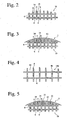
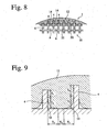
- Stress release portions formed between the peripheral wall layer 12 and the grooves 14 are, for instance, voids 22 between the peripheral wall layer 12 and the grooves 14 as shown in Figs. 8 and 9 .
- the voids 22 are space at corners of the grooves 14, which are not filled with the peripheral wall layer 12.
- a thermal shock stress generated in the peripheral wall layer 12 by rapid heating by an exhaust gas is released more easily in the honeycomb structure having the voids 22 between the peripheral wall layer 12 and the grooves 14 than in the honeycomb structure having grooves filled up with the peripheral wall layer 12 to their corners without voids as shown in Fig. 3 .
- the number of the grooves 14 having the voids 22 is preferably 5% or more, more preferably 20 to 90%, based on the total number of the grooves 14.
- the grooves 14 having the voids 22 are defined as those meeting the conditions that the total length of a contact portion of the grooves 14 with the peripheral wall layer 12, i.e. T 1 + T 4 + T 6 , is 95% or less based on the total length of the grooves 14, i.e. T 1 + T 2 + T 3 + T 4 + T 5 + T 6 + T 7 .
- the voids 22 between the peripheral wall layer 12 and the grooves 14 are preferably formed continuously in an axial direction of the honeycomb structure 1, because it can release thermal shock stress throughout the honeycomb structure 1. However, the voids 22 need not be uniform along the entire axial length.
- the stress release portions provide the ceramic honeycomb structure with a remarkably improved thermal shock resistance.
- One example of a method for producing a ceramic honeycomb structure having voids 21 in a peripheral wall layer 12 comprises removing a peripheral wall 3 and cell walls 4 adjacent thereto from a ceramic honeycomb green or fired body, covering the resultant axial grooves 14 with a coating material composed of a ceramic aggregate and an inorganic binder, and charging the coated body into a drying furnace (for instance, 70°C or higher) to rapidly dry the coating. Rapid vaporization of water in the coating material provides the peripheral wall layer 12 with crack-shaped voids 21 open on a surface thereof. Rapid drying produces the voids 21 because difference occurs in the water content between surface and interior portions of the coating, resulting in different volume shrinkage ratios between them.
- a drying furnace for instance, 70°C or higher
- the coating material may be properly selected like the above-described material for the peripheral wall layer 12.
- the percentage of the voids 21 and the width and shape of their openings may be changed by adjusting the amount and kind of ceramic aggregates and inorganic or organic binders added, water content in the coating material, or the temperature of the drying furnace, etc. When the amounts of an inorganic binder and water added are increased, the generation of the voids 21 becomes easy. After drying the coating material, it may be fired, if necessary.
- the peripheral wall 3 of the ceramic green or fired body having a honeycomb structure is removed to expose axial grooves 14, which are coated with a coating material having a viscosity of 20,000 cP or more and then dried.
- the ceramic honeycomb green or fired body may be fired, if necessary, before or after coated with the coating material.
- the applied coating material having a viscosity of 10,000 to 20,000 cP is likely to fill up the corners of the grooves 14 as shown in Fig. 3 .
- a coating material having as high a viscosity as 20,000 cP or more is not likely to fill up the corners of the grooves 14 as shown in Figs. 8 and 9 , resulting in a ceramic honeycomb structure 1 having voids 22 between the peripheral wall layer 12 and the grooves 14.
- the viscosity of the coating material can be made as high as 20,000 cP or more.
- the coating material may be fired after dried, if necessary.
- the ceramic honeycomb structure according to the second embodiment comprises a ceramic honeycomb body having grooves axially extending on its outer surface and cell walls constituting a large number of flow paths inside the grooves, and a peripheral wall layer covering the grooves, a thermal expansion coefficient of the peripheral wall layer being smaller than those of the cell walls in a radial direction.
- the peripheral wall layer made of a coating material having a smaller thermal expansion coefficient than those of the cell walls is cooled to room temperature after drying or firing, a compressive stress remains in the peripheral wall layer, while a tensile stress remains in the cell walls, because of the difference in a thermal expansion coefficient between the cell walls and the peripheral wall layer. Therefore, even if the ceramic honeycomb structure has a higher temperature in a center portion than in a peripheral wall layer particularly at the time of starting operation, the compressive stress prevents the peripheral wall layer from being cracked.
- the thermal expansion coefficient of the peripheral wall layer is smaller by 0.1 ⁇ 10 -7 /°C or more than those of the cell walls in a radial direction.
- the thermal expansion coefficient of the cell walls in a radial direction is about 10.1 to 20.0 ⁇ 10 -7 /°C. Accordingly, if the thermal expansion coefficient of the peripheral wall layer were about 10.0 ⁇ 10 -7 /°C or less, it would be able to prevent cracking from occurring in the peripheral wall layer due to the difference in thermal expansion by the temperature difference between the peripheral wall layer and the center portion in the honeycomb structure during usual use.
- the thermal expansion coefficient of the peripheral wall layer is preferably 9.0 ⁇ 10 -7 /°C or less (1.0 ⁇ 10 -7 /°C or more smaller than those of the cell walls), more preferably 8.0 ⁇ 10 -7 /°C or less (2.0 ⁇ 10 -7 /°C or more smaller than those of the cell walls) in a radial direction.
- the coating material containing amorphous silica particles having as low a thermal expansion coefficient as 10.0 ⁇ 10 -7 /°C or less, and an amorphous oxide matrix having high strength and excellent bonding with amorphous silica particles provides the peripheral wall layer with a smaller thermal expansion coefficient than those of the cell walls. Because aggregates composed of amorphous silica particles have higher hardness than that of the cordierite aggregates described in Japanese Patents 2,604,876 and 2,613,729 , the peripheral wall layer can be provided with high hardness.
- All ceramic particles (aggregates) of the peripheral wall layer need not be amorphous silica particles. 50% or more by mass of the amorphous silica particles provide the peripheral wall layer with a low thermal expansion coefficient.
- the amorphous silica particles have an average particle size of 1 to 100 ⁇ m, the peripheral wall layer having excellent strength and thermal shock resistance can be obtained.
- the average particle size of the amorphous silica particles is less than 1 ⁇ m, a large amount of the amorphous oxide matrix for binding amorphous silica particles are required, providing the peripheral wall layer with too low a thermal shock resistance.
- the average particle size of the amorphous silica particles exceeds 100 ⁇ m, the strength of the peripheral wall layer is lowered.
- the more preferred average particle size of the silica particles is 5 to 40 ⁇ m.
- the amorphous silica particles preferably have a shape as close to a sphere as possible. For instance, when the aspect ratio (ratio of major axis/minor axis) of the amorphous silica particles is 20 or less, the amorphous silica particles have a small surface area, requiring only a small amount of the amorphous oxide matrix to bond the amorphous silica particles, thereby making it possible to provide the peripheral wall layer with an excellent thermal shock resistance.
- the aspect ratio of the amorphous silica particles is preferably 10 or less, more preferably 5 or less.
- a soft ceramic material comprising a cordierite-forming material is shaped by extrusion to produce a green body having an integral honeycomb structure constituted by cell walls and a peripheral wall, and the green body is fired.
- the peripheral wall is thicker than the cell walls, and the degree of orientation of cordierite crystals is lower in the peripheral wall than in the cell walls, so that the thermal expansion coefficient of the peripheral wall is equal to or higher than those of the cell walls. Accordingly, it is preferable that after the peripheral wall integral with the cell walls is completely removed by machining, a peripheral wall layer having a smaller thermal expansion coefficient than those of the cell walls is formed.
- the honeycomb body and the peripheral wall layer can be strongly bonded to each other. Also, by removing cell walls having deformed outer walls the honeycomb structure can be provided with high mechanical strength. In addition, even when the fired honeycomb structure entirely has low roundness, it is provided with improved dimensional accuracy, because the peripheral wall layer is formed after being provided with increased roundness by grinding.
- the removal of the peripheral wall may be carried out either in a state of a honeycomb green body or in a state of a fired body, it is preferably carried out on a dried honeycomb green body from the aspect of reducing the working cost, or on a fired body from the aspect of securing the dimensional accuracy.
- a coating material containing amorphous silica particles and an amorphous ceramic matrix it has a lower melting point than those of ceramics (cordierite, etc.) forming the ceramic honeycomb body. Accordingly, it is preferable that the coating material is applied to the honeycomb body fired after removing the peripheral wall, and that the coated honeycomb is then dried and fired.
- a peripheral wall layer fixed to the grooves strongly and having an excellent thermal shock resistance due to a smaller thermal expansion coefficient than those of the cell walls.
- the coating material for the peripheral wall layer preferably comprises 100 parts by mass of the amorphous silica particles and 2 to 35 parts by mass of an amorphous oxide matrix.
- the amorphous oxide matrix is less than 2 parts by mass, the amorphous silica particles cannot be strongly bonded.
- the amorphous oxide matrix exceeds 35 parts by mass, the peripheral wall layer is likely to be cracked at the time of drying or firing, or by thermal shock.
- Oxide colloids composed of colloidal silica and/or colloidal alumina are suitable for the amorphous ceramic matrix because of the effect of improving coatability.
- the coating material for the peripheral wall layer may contain ceramic fibers, cement, etc., and further an organic binder, etc.
- the peripheral wall layer composed of amorphous silica particles and an amorphous oxide matrix formed from colloidal silica and/or colloidal alumina preferably contains 70% or more by mass of SiO 2, and may further contain proper amounts of Al 2 O 3 , MgO, Fe 2 O 3 , TiO 2 , Na 2 O, K 2 O, CaO, etc.
- the SiO 2 content is preferably 80% or more by mass, more preferably 90% or more by mass.
- a peripheral wall layer formed from a coating material comprising 100 parts by mass of amorphous silica particles and 2 to 35 parts by mass (on a solid basis) of an amorphous oxide matrix (preferably colloidal silica and/or colloidal alumina) is formed to obtain a ceramic honeycomb structure whose peripheral wall layer is resistant to cracking not only when used for exhaust gas-cleaning catalytic converters and particulate-capturing filters, which are subjected to a large thermal shock, but also while handling.
- the coating material may contain ceramic fibers, cement, etc. and further an organic binder, etc, in addition to the above basic components.
- an oxide colloid such as colloidal silica and/or colloidal alumina, etc. may be applied to the surface of the peripheral wall layer.
- the peripheral wall and the nearby cell walls of the honeycomb green body is removed before firing. Because the peripheral wall and the cell walls have high hardness after firing, the cutting of the peripheral wall and the nearby cell walls is likely to cause chipping in the cell walls and takes a lot of time. On the other hand, because the peripheral wall and the cell walls are easily cut because of low hardness before firing, the removal of the peripheral wall and the nearby cell walls by cutting can be carried out in a short period of time without chipping in the cell walls.
- the cell walls 4 are resistant to chipping 4a during removing the peripheral wall 3 of the fired body, thereby sufficiently keeping an contact area between the cell walls 4 and the peripheral wall layer 12. Further, when the peripheral wall 3 is removed at the stage of the dried green body, it can be cut away, thereby shortening the working time. Because cutting tools such as cemented carbide cutting tools, etc. can be used in place of a diamond grinder wheels, the working cost can be reduced.
- a coating material is applied to the grooves 14 before or after the firing (see Figs. 13(a) and 13(b) ), and then dried and fired, to form a peripheral wall layer 12 integral with the grooves 14. Because this peripheral wall layer 12 is resistant to peeling off from the honeycomb body 10, the honeycomb structure has excellent isostatic strength.
- peripheral wall includes not only the peripheral wall of the honeycomb green or fired body but also the nearby cell walls thereof unless otherwise mentioned.
- the cell walls 4 near the peripheral wall 12 are removed, preferably at least two cells, more preferably 3 to 4 cells, are removed from the periphery.
- the dried ceramic honeycomb green body may be fired, and its exposed peripheral surface may be finish-worked and then formed with a peripheral wall layer 12.
- the peripheral wall layer 12 may be formed, and a peripheral surface of the peripheral wall layer 12 may be worked depending on applications.
- the dimensional changes of these parts by firing can be made identical, thereby making them integral with each other while preventing cracking by firing.
- the green body 41 in the firing of the ceramic honeycomb green body 41, the green body 41 is placed on a table 40 such that a longitudinal end of the ceramic honeycomb green body 41 abuts a table 40, and a large-diameter portion 44 of the ceramic honeycomb body 42 in contact with the table 40 is cut off after firing, to obtain a honeycomb body 43 having a uniform outer diameter; which provides a honeycomb structure with a peripheral wall layer having a uniform thickness.
- dimensional decrease In the course of a firing reaction of ceramics, dimensional decrease generally occurs. There is no problem when the dimensional decrease occurs uniformly in the overall honeycomb structure. However, in the case of a large ceramic honeycomb structure (for instance, 150 mm or more in an outer diameter, 150 mm or more in length) for cleaning an exhaust gas from diesel engines, the degree of dimensional decrease differs from portion to portion in the ceramic honeycomb structure depending on its materials. For instance, because an opening end of the honeycomb green body abutting the table is constrained by the table, it suffers from only small dimensional decrease.
- the dried green body 41 has a uniform outer diameter as shown in Fig. 10(a)
- its opening end 44 abutting the table 40 is subjected to less diameter decrease by firing, resulting in poorer roundness than other portions, because of constraint by the table 40 as shown in Fig. 10(b) .
- the peripheral wall layer 12 having the same outer diameter as that of the disks 51, 51 is formed by coating the grooves 14 appearing on the fired ceramic honeycomb with a coating material, with both end portions of the fired ceramic honeycomb having a nonuniform outer diameter sandwiched by a pair of disks 51, 51 having a targeted outer diameter as shown in Fig.
- the resultant peripheral wall layer 12 has a nonuniform thickness, so that the peripheral wall layer 12 is easily subjected to cracking due to thermal shock in a thick portion. Accordingly, it is preferable to remove an opening end 44 having a larger outer diameter, thereby making the outer diameter of the fired ceramic honeycomb 43 uniform as shown in Fig. 10(c) .
- the thickness of the peripheral wall layer of the honeycomb structure can also be made uniform by removing the peripheral wall according to the predicted diameter decrease by firing. For instance, when the green body 45 is worked to a shape shown in Fig. 11(a) (a portion 47 abutting the table 40 has a reduced diameter), based on a dimensional change ratio determine on each portion of the honeycomb structure in the production of the fired body shown in Fig. 10(b) from the green body shown in Fig. 10(a) , the fired body 46 with good dimensional accuracy can be obtained as shown in Fig. 11(b) . Using this fired body, it is possible to produce a peripheral wall layer 12 having a uniform thickness with the disks 51, 51 shown in Fig. 12 .
- the extent of cutting the peripheral wall of the ceramic green body can be determined, based on the dimensional change ratio measured by a three-dimensional meter in the production of a fired body from a green body, and the green body can be worked based on the above extent of cutting by a three-dimensional machining apparatus, etc.
- the cell walls 4 preferably have a porosity of 50 to 80%.
- the cell walls 4 have a porosity of 50% or more, materials forming the peripheral wall layer 12 easily penetrate into the pores of the cell walls 4, resulting in a so-called large anchoring effect.
- the peripheral wall layer 12 and the grooves 14 are integrally bonded by the anchoring effect, the honeycomb structure 1 has a large mechanical strength.
- the porosity exceeds 80%, the strength of the cell walls 4, thus the mechanical strength such as isostatic strength, etc. of the honeycomb structure 1, is too low.
- the mechanical strength such as isostatic strength, etc. decreases, the honeycomb structure 1 becomes easily broken by mechanical stress such as engine vibration, road surface vibration, etc., in a case where it is used as a catalyst carrier or a particulate-capturing filter.
- the cell walls 4 preferably have an average pore size of 10 to 50 ⁇ m.
- the average pore size is 10 ⁇ m or more, the materials forming the peripheral wall layer 12 easily penetrate into the pores of the cell walls 4, resulting in a large anchoring effect.
- the average pore size exceeds 50 ⁇ m, the strength of the cell walls 4 undesirable decreases.
- the ceramic honeycomb structures described in Japanese Patents 2,604,876 and 2,613,729 would have a low thermal shock resistance, while the decrease of the thermal shock resistance of the ceramic honeycomb structure 1 having stress release portions would be suppressed.
- soft ceramic materials having excellent heat resistance are preferably used at least for a ceramic honeycomb body. It is particularly preferable to use at least one soft ceramic material selected from the group consisting of cordierite, alumina, mullite, silicon nitride, silicon carbide and LAS. Most preferable among them is cordierite because it is inexpensive and excellent in heat resistance and chemical resistance with a low thermal expansion.
- the thermal expansion coefficients of the grooves 14 and the peripheral wall layer 12 need not necessarily be identical because of the improved thermal shock resistance.
- the peripheral wall layer 12 may be formed, for instance, by a coating material comprising heat-resistant ceramic aggregates such as cordierite, silica, alumina, mullite, silicon carbide, silicon nitride, etc., an inorganic binder, and if necessary, ceramic fibers, an organic binder, cement, etc.
- the cell walls 4 of the ceramic honeycomb structure 1 preferably have a thickness of 0.1 to 0.5 mm. Particularly, in the case of a large honeycomb structure having an outer diameter exceeding 150 mm, the strength of the cell walls 4 is insufficient with a thickness less than 0.1 mm. On the other hand, when the thickness of the cell walls 4 exceeds 0.5 mm, an exhaust gas-passing resistance (pressure loss) of the cell walls 4 becomes large.
- the thickness of the cell walls 4 is more preferably 0.2 to 0.4 mm.
- the cell walls 4 preferably have a pitch of 1.3 mm or more. When the pitch is less than 1.3 mm, the cell opening area of the honeycomb structure 1 is too small, increasing the pressure loss of the honeycomb filter 1 and thus decreasing an engine power.
- the peripheral wall layer 12 does not easily peel off from the honeycomb body 10, thereby securing a proper holding force in a container (not shown), and thus making it unlikely that the honeycomb structure 1 is damaged by moving in the container.
- the ceramic honeycomb body 10 more preferably has an isostatic strength of 1.5 MPa or more.
- each Example and Comparative Example the porosity and average pore size of the ceramic honeycomb body were measured by a mercury penetration method on test pieces cut out therefrom.
- the thermal expansion coefficient of each ceramic honeycomb structure is an average value of thermal expansion coefficients between room temperature and 800°C.
- the method for measuring a thermal shock resistance temperature comprises keeping each ceramic honeycomb structure in an electric furnace at a temperature of room temperature + 400°C for 30 minutes, quenching it to room temperature, and then observing by the naked eye whether or not the cell walls of the ceramic honeycomb structure are cracked on both longitudinal end surfaces, and if there are no cracks in the cell walls, elevating the temperature of the electric furnace stepwise each by 25°C, to repeat the measurement until cracking occurs.
- the thermal shock resistance temperature is a difference between a temperature at which cracking starts to occur and room temperature.
- the method for measuring isostatic strength comprises charging each ceramic honeycomb structure into a pressure container with 20-mm-thick aluminum plates abutting both longitudinal end surfaces of the ceramic honeycomb structure to seal both ends thereof and with a 2-mm-thick rubber closely attaching to the peripheral wall layer surface of the ceramic honeycomb structure, and introducing water into the pressure container to apply a hydrostatic pressure to the ceramic honeycomb structure, according to the automobile standards (JASO) of the Society of Automotive Engineers of Japan, Inc.
- the isostatic strength is a pressure (MPa) when each ceramic honeycomb structure is broken.
- a cordierite-forming material powder comprising kaolin powder, talc powder, silica powder and alumina powder as main components was prepared.
- the material powder contained 48 to 52% by mass of SiO 2 33 to 37% by mass of Al 2 O 3 , and 12 to 15% by mass of MgO as main components, and further a binder such as methylcellulose, hydroxypropylmethylcellulose, etc., a lubricant, and graphite (a pore-forming agent).
- a binder such as methylcellulose, hydroxypropylmethylcellulose, etc., a lubricant, and graphite (a pore-forming agent).
- the soft ceramic material was shaped by extrusion to form a honeycomb green body integrally having a peripheral wall 3 and cell walls 4, and then drying and firing the honeycomb green body to form a fired cordierite honeycomb having an outer diameter of 280 mm and a full length of 300 mm.
- the cell walls of each fired body had a porosity of 65%, an average pore size of 20 ⁇ m, a thickness of 0.3 mm, a pitch of 1.5 mm and a thermal expansion coefficient of 10.5 ⁇ 10 -7 /°C in a radial direction.
- a peripheral wall was removed from each fired cordierite honeycomb by a cylindrical grinder to form a ceramic honeycomb body 10 (an outer diameter of 265.7 mm, a length of 300 mm) having axial grooves.
- cordierite powder A an average particle size of 10 ⁇ m
- colloidal silica 100 parts by mass was formulated with 10 to 15 parts by mass (on a solid basis) of colloidal silica, and 1.2 parts by mass of methylcellulose was further added to the total (100 parts by mass) of the cordierite powder A and the colloidal silica, and kneaded with water to form a coating material having a viscosity of 15,000 to 19,000 cP.
- each ceramic honeycomb structure 1 The voids 21 in the peripheral wall layer 12 of each ceramic honeycomb structure 1 were observed by the naked eye, to calculate the length of each observed voids 21 by approximation to a straight line, and the total length of the voids 21 in one ceramic honeycomb structure 1 was then calculated. With the calculated value, a ratio of the total length of the voids 21 to the full length of the honeycomb structure 1 was calculated. Each ceramic honeycomb structure 1 was measured with respect to a thermal shock resistance temperature and an isostatic strength. The results are shown in Table 2.
- each ceramic honeycomb structure 1 had voids 21 in the peripheral wall layer 12, a thermal shock stress was released from the ceramic honeycomb structure 1 to prevent cracking due to thermal shock in the cell walls 4. Accordingly, the thermal shock resistance temperature was 550 to 625°C in each Example. Because the peripheral wall layer 12 filled the axial directional grooves 14, the isostatic strength exceeded 1 MPa, causing no problem in a practical use. It was found that the larger the ratio of the total length of the voids 21 to the full length of the honeycomb structure 1, the higher the thermal shock resistance temperature. It was also confirmed that when the total length of the voids 21 was equal to or more than the full length of the honeycomb structure 1, the honeycomb structure 1 had a high thermal shock resistance temperature.
- the fired cordierite honeycomb of 265.7 mm in an outer diameter and 300 mm in a full length which was produced in the same manner as in Example 1, was used as a ceramic honeycomb structure of Comparative Example 1 without forming a peripheral wall layer. Also, after removing a peripheral wall from the fired ceramic honeycomb of Comparative Example 1, a peripheral surface thereof was coated with a coating material having a viscosity of 15,000 cP, which comprised 100 parts by mass of cordierite powder A having an average particle size of 10 ⁇ m, and 10 parts by mass (on a solid basis) of colloidal silica, and further 1.2 parts by mass of methylcellulose per the total (100 parts by mass) of the cordierite powder A and the colloidal silica.
- a coating material having a viscosity of 15,000 cP which comprised 100 parts by mass of cordierite powder A having an average particle size of 10 ⁇ m, and 10 parts by mass (on a solid basis) of colloidal silica, and further 1.2 parts by mass of
- the ceramic honeycomb structure was dried in a drying furnace at 40°C for 24 hours, and then dried in a drying furnace at 70°C for 12 hours, and further heated to 450°C, to provide a ceramic honeycomb structure of Comparative Example 2 integrally having grooves 14 and a peripheral wall layer 12.
- the thermal shock resistance temperature and the isostatic strength of each ceramic honeycomb structure were measured in the same manner as in Example 1. The results are shown in Table 3. Table 3 No.
- Comparative Example 1 Comparative Example 2 Coating Material Aggregates - Cordierite Particles A 100 parts by mass Inorganic Binder - Colloidal Silica 10 parts by mass Viscosity (cP) - 15,000 Drying Conditions - at 40°C for 24 hours at 70°C for 12 hours Voids in Peripheral Wall Layer - None Thermal Shock Resistance Temperature (°C) 650 400 Isostatic Strength (MPa) - 2.5
- the ceramic honeycomb structure 1 of Comparative Example 1 without a peripheral wall layer was free from a problem concerning the thermal expansion difference between the cell walls 4 and the peripheral wall layer 12.
- a thermal shock exceeding 650°C was applied, cracking occurred in the cell walls 4 by a thermal stress due to the temperature difference between a center portion and a surface portion, because of its large size.
- the ceramic honeycomb structure 1 of Comparative Example 1 did not have a peripheral wall layer, the rubber could not be closely fixed thereto, failing to measure its isostatic strength.
- the honeycomb structure having no peripheral wall layer could not be substantially held in a metal container by a grip member, it could not be used as a catalyst carrier or a particulate-capturing filter.
- the peripheral wall layer 12 filled the corners of the grooves 14. However, because the drying temperature of the coating material was at first as low as 40°C, no voids were generated in the peripheral wall layer 12. Also, because the ceramic honeycomb structure 1 of Comparative Example 2 had a peripheral wall layer 12 strongly integrated with cell walls 4, it exhibited a higher isostatic strength than that of the ceramic honeycomb structure of Example 1. However, because it did not have portions for releasing thermal shock stress, its thermal shock resistance temperature was as low as 400°C.
- the cell walls of each ceramic honeycomb body 10 had a porosity of 65%, an average pore size of 20 ⁇ m, a thickness of 0.3 mm, a pitch of 1.5 mm and a thermal expansion coefficient of 10.5 ⁇ 10 -7 /°C in a radial direction.
- a coating material having a viscosity of 25,000 to 67,000 cP was produced by mixing 100 parts by mass of cordierite powder B having an average particle size of 20 ⁇ m with 10 parts by mass (on a solid basis) of colloidal silica and further methylcellulose and water in proper amounts and kneading them.
- the coating material was applied to the periphery of the honeycomb body 10, dried at 40°C for 24 hours, and then dried at 70°C for 12 hours. Because of a low initial drying temperature, no voids 21 were generated in the peripheral wall layer 12.
- the coated honeycomb body was heated to 450°C to remove methylcellulose by decomposition, to produce a ceramic honeycomb structure having an outer diameter of 266.7 mm and a full length of 300 mm, in which grooves 14 were integral with a peripheral wall layer 12.
- each ceramic honeycomb structure 1 The thermal shock resistance temperature and isostatic strength of each ceramic honeycomb structure 1 were measured. Further, the peripheral wall layer 12 filled into the grooves 14 was observed on a longitudinal cross section of the honeycomb structure 1, to count the number of grooves 14 having voids 22 between the peripheral wall layer 12 and themselves among all the grooves 14. The results are shown in Table 4.
- each ceramic honeycomb structure of Examples 7 to 11 had voids 22 between the peripheral wall layer 12 and the grooves 14, even though cracking occurred due to a thermal shock stress in the peripheral wall layer 12, the cracking would not propagate into the cell walls 4 because the voids 22 released a thermal shock stress from the ceramic honeycomb structure. Therefore, as compared with the ceramic honeycomb structure 1 of Comparative Example 2, in which the grooves 14 were filled with a peripheral wall layer 12 to their corners, cracks due to thermal shock did not easily propagate into the cell walls 4, resulting in showing a high thermal shock resistance temperature. In addition, despite the voids 22 between the peripheral wall layer 12 and the grooves 14, the isostatic strength was as high as more than 1 MPa, a practically acceptable level.
- the cell walls of each honeycomb body 10 had a porosity of 65%, an average pore size of 20 ⁇ m, a thickness of 0.3 mm, a pitch of 1.5 mm and a thermal expansion coefficient of 10.5 ⁇ 10 -7 /°C in a radial direction.
- the same coating material as in Comparative Example 2 except for having a viscosity of 52,000 cP was applied to a peripheral wall of each honeycomb body 10.
- the coated honeycomb body 10 was rapidly heated and dried by hot blast in a drying furnace at 70°C or 100°C as shown in Table 5.
- amorphous silica powder A having an average particle size of 15 ⁇ m 100 parts by mass of amorphous silica powder A having an average particle size of 15 ⁇ m was mixed with 7 parts by mass (on a solid basis) of colloidal silica, and further with 1.2 parts by mass of methylcellulose per the total (100 parts by mass) of the amorphous silica powder A and the colloidal silica, and then kneaded with water, to produce a coating material having a viscosity of 45,000 cP.
- the ceramic honeycomb structures of Examples 14 and 15 were produced in the same manner as in Examples 12 and 13 except for using the above coating material.
- Table 5 also shows the shape of voids 21, the ratio of the total length of voids 21 to the full length of the honeycomb structure, the percentages of grooves 14 having voids 22 between the peripheral wall layer 12 and themselves among the overall grooves.
- each ceramic honeycomb structure 1 of Examples 12 to 15 had voids 21. in a peripheral wall layer 12, and voids 22 between the peripheral wall layer 12 and grooves 14, these voids 21, 22 functioning to release thermal shock stress prevented cracks due to thermal shock from propagating into the cell walls 4. Accordingly, the ceramic honeycomb structures 1 of Examples 12 to 15 had higher thermal shock resistance temperatures than that of the ceramic honeycomb structure of Comparative Example 2. In addition, because of two types of voids (stress release portions) 21, 22 in the peripheral wall layer 12 and between the peripheral wall layer 12 and the grooves 14, the ceramic honeycomb structures of Examples 12 to 15 had higher thermal shock resistance temperatures than those of the honeycomb structures of Examples 1 to 6 and 7 to 11. With respect to the isostatic strength, it was as high as more than 1 MPa, a practically acceptable level, because of the peripheral wall layer 12 formed by applying a coating material to the axial grooves 14.
- a fired cordierite honeycomb produced in the same manner in Example 1 had cell walls, which had a porosity of 65%, an average pore size of 20 ⁇ m, a thickness of 0.3 mm, a pitch of 1.5 mm and a thermal expansion coefficient of 10.5 ⁇ 10 -7 /°C in a radial direction, was deprived of a peripheral wall by a cylindrical grinder to provide a honeycomb body A having an outer diameter of 264.7 mm and a full length of 300 mm, which had grooves on its periphery.
- each honeycomb body A was coated with an coatable pasty material having the formulation shown in Table 6, which was kneaded with an organic binder and water, in a dry thickness of about 1 mm, and the coated layer was dried to provide a ceramic honeycomb structure 1 having an outer diameter of 266.7 mm and a full length of 300 mm.
- the peripheral wall layer 12 of the ceramic honeycomb structure 1 was scratched by rotating a core hardness tester (type PKH) available from George Fischer Corporation by two rounds, and the depth of scratch (measure of surface hardness) in the peripheral wall layer 12 of each ceramic honeycomb structure 1 was measured by Quick Vision, a non-contact three-dimensional meter available from Mitsutoyo Corporation.
- the thermal shock resistance temperature was measured on three ceramic honeycomb structures 1 in each Example. Test pieces were cut out from the peripheral wall layer 12, to measure an average thermal expansion coefficient between 40°C and 800°C. The results are shown in Table 6.
- peripheral wall layer 12 of each ceramic honeycomb structure 1 was composed of amorphous silica particles A and colloidal silica, the depth of scratch in the peripheral wall layer 12 was 0.45 mm or less, a practically acceptable level. Also, because the thermal expansion coefficient of the peripheral wall layer 12 was smaller than the thermal expansion coefficients (10.5 ⁇ 10 -7 /°C) of the cell walls in a radial direction, the thermal shock resistance temperature was 550°C or higher, a practically acceptable level.
- Each coating material produced in the same manner as in Examples 16 to 19 except for having the formulation shown in Table 6 was applied in a dry thickness of about 1 mm to the peripheral surface of the same honeycomb body A as in Examples 16 to 19, dried, and further fired at 850°C for 2 hours, to provide a ceramic honeycomb structure 1 having an outer diameter of 266.7 mm and a full length of 300 mm.
- the depth of scratch, thermal expansion coefficient and thermal shock resistance temperature of the peripheral wall layer 12 were measured in the same manner as in Example 16. The results are shown in Table 6. Because any of the peripheral wall layers 12 of Examples 20 to 23 was composed of amorphous silica particles B and colloidal silica, its surface hardness (expressed by the depth of scratch) was 0.45 mm or less, a practically acceptable level. Also, because the thermal expansion coefficient of the peripheral wall layer 12 was smaller than the thermal expansion coefficients (10.5 ⁇ 10 -7 /°C) of the cell walls in a radial direction, the thermal shock resistance temperature was 550°C or higher, a practically acceptable level.
- honeycomb green body having an outer diameter of 290 mm and a full length of 320 mm which was produced in the same manner as in Example 16, was dried, deprived of a peripheral wall and both end portions by grinding and then fired, to provide a honeycomb body B having an outer diameter of 264.7 mm and a full length of 300 mm, which had grooves on its periphery.
- Each honeycomb body B was coated with a coating material in the same manner as in Examples 16 to 19 to provide a ceramic honeycomb structure 1.
- Example 16 With respect to each ceramic honeycomb structure 1, the depth of scratch, thermal expansion coefficient and thermal shock resistance temperature of the peripheral wall layer 12 were measured in the same manner as in Example 16. The results are shown in Table 6. Examples 24 to 27 were the same as Examples 16 to 19 except that the former removed the peripheral wall 3 before firing, and the depth of scratch in the peripheral wall layers 12 of their ceramic honeycomb structures 1 was 0.45 mm or less, a practically acceptable level. Because the thermal expansion coefficients of the peripheral wall layers 12 were smaller than the thermal expansion coefficients (10.5 ⁇ 10 -7 /°C) of the cell walls in a radial direction in the ceramic honeycomb structures 1 of Examples 24 to 27, their thermal shock resistance temperatures were 550°C or higher, a practically acceptable level.
- a honeycomb body A having an outer diameter of 264.7 mm and a full length of 300 mm was produced in the same manner as in Example 16.
- a ceramic honeycomb structure 1 having an outer diameter of 266.7 mm and a full length of 300 mm was produced in the same manner as in Examples 16 to 19 except for coating each honeycomb body A with a coating material having the formulation shown in Table 6.
- Example 28 The coating material of Example 28 was composed of 100 parts by mass of mixed particles comprising 90% by mass of amorphous silica particles A and 10% by mass of quartz particles and 7 parts by mass of colloidal silica.
- the coating material of Example 29 was composed of 100 parts by mass of amorphous silica particles A and 7 parts by mass of colloidal alumina. Accordingly, in any of the ceramic honeycomb structures 1, the depth of scratch in the peripheral wall layer 12 was 0.45 mm or less, a practically acceptable level.
- the thermal shock resistance temperature was 550°C or higher, a practically acceptable level.
- the cell walls of this ceramic honeycomb body C had a porosity of 65%, an average pore size of 20 ⁇ m, a thickness of 0.3 mm, a pitch of 1.5 mm and a thermal expansion coefficient of 10.5 ⁇ 10 -7 /°C in a radial direction.
- the depth of scratch, thermal expansion coefficient and thermal shock resistance temperature of the peripheral wall 3 were measured in the same manner as in Example 16. The results are shown in Table 6.
- the thermal shock resistance temperature was lower than 550°C.
- a honeycomb structure green body integrally having a peripheral wall 3 and cell walls 4 was produced in the same manner as in Example 1.
- This green body was dried in an induction-drying furnace. Gripped by a jig on a lathe, the dried green body was rotated at 260 rpm to remove a deformed portion as deep as three cells from its peripheral portion by a cemented carbide cutting tool under the conditions of a cutting depth of 5 mm and a feed of 1.0 mm/second, to provide a honeycomb body 10 with grooves exposed on its periphery.
- This honeycomb body 10 was charged into a firing furnace with its one open end abutting a honeycomb table, and temperature elevation was carried out at a speed of 5°C/hour from room temperature to 500°C, and then at a speed of 20°C/hour from 500°C to 1425°C, followed by keeping it at the highest temperature for 10 hours. After firing, it was slowly cooled to obtain a fired honeycomb having an outer diameter of 264.7 to 265.7 mm and a length of 300 mm.
- the cell walls of this fired honeycomb had a porosity of 65%, an average pore size of 20 ⁇ m, a thickness of 0.3 mm, a pitch of 1.5 mm and a thermal expansion coefficient of 10.5 ⁇ 10 -7 /°C in a radial direction.
- a pasty coating material comprising 100 parts by mass of cordierite particles having an average particle size of 10 ⁇ m and 7 parts by mass (on a solid basis) of colloidal silica and kneaded with an organic binder and water was applied to a peripheral surface of the fired honeycomb 10 such that its outer diameter became 266.7 mm. Thereafter, it was dried at 120°C for 2 hours and then fired at 850°C for 2 hours.
- the thickness of the peripheral wall layer 12 in the resultant honeycomb structure was 0.5 to 1.5 mm (see Fig. 13(a) ).
- the isostatic strength of the honeycomb structure 1 was measured in the same manner as in Example 1.
- the honeycomb structure 1 was regarded as "good” when the isostatic strength was 1.0 MPa or more and less than 1.5 MPa, “excellent” when the isostatic strength was 1.5 MPa or more, and “poor” when the isostatic strength was less than 1.0 MPa.
- the honeycomb structure 1 was regarded as "pass” when the isostatic strength was 1.0 MPa, or more, and “fail” when it was less than 1.0 MPa.
- the thermal shock resistance temperature of the ceramic honeycomb structure 1 was measured in the same manner as in Example 1.
- the honeycomb structure 1 was regarded as "good” when the thermal shock resistance temperature was 500°C or higher, “excellent” when it was 550°C or higher, and “poor” when it was lower than 500°C. Incidentally, the honeycomb structure 1 was regarded as "pass” when the thermal shock resistance temperature was 500°C or higher, and “fail” when it was lower than 500°C. The results are shown in Table 7.
- a honeycomb body 10 from which a peripheral wall was removed, was produced in the same manner as in Example 30. 100 parts by mass of the same cordierite-forming material powder as the honeycomb body was mixed with 0.5 parts by mass, of methylcellulose, a dispersant and water, to form a coatable pasty material. Sandwiched by a pair of grip members 51, 51 shown in Fig. 12 , this honeycomb body 10 was coated with the coating material in a post-firing thickness of about 1.6 mm, to form a peripheral wall layer 12.
- the honeycomb body 10 provided with the peripheral wall layer 12 was charged into a firing furnace such that its one open end abutted a honeycomb table, and fired under the same conditions as in Example 30 to obtain a fired honeycomb having an outer diameter of 266.7 to 267.7 mm and a length of 300 mm. Because the outer diameter of the honeycomb body 10 after firing was 266.7 to 267.7 mm due to dimensional change, a large outer-diameter portion was removed to make it uniform at 266.7 mm. The thickness of the peripheral wall layer 10 was 0.6 to 1.6 mm (see the steps in Fig. 13(b) ). The isostatic strength and thermal shock resistance temperature of the resultant honeycomb structure 1 were measured in the same manner as in Example 30. The results are shown in Table 7.
- a green body having a honeycomb structure was produced in the same manner as in Example 30.
- the peripheral wall 3 of the green body had deformed portions due to its own weight.
- the green body was charged into a firing furnace such that its one open end abutted a honeycomb table, and fired under the same conditions as in Example 30 to obtain a fired honeycomb having an outer diameter of 274.7 mm and a length of 300 mm. There were many fired honeycombs that were cracked under the influence of the deformation of the peripheral wall 3.
- the cell walls of this fired honeycomb had a porosity of 65%, an average pore size of 20 ⁇ m, a thickness of 0.3 mm, a pitch of 1.5 mm, and a thermal expansion coefficient of 10.5 ⁇ 10 -7 /°C in a radial direction.
- Fired honeycombs subjected to no cracking in the firing step were mounted to a periphery grinding machine, to cut the peripheral walls 3 and the nearby cell walls 4 to a depth of about 4.5 mm (equivalent to three cells), thereby obtaining a honeycomb body 10 having an outer diameter of 265.7 mm, which had grooves on its periphery.
- a diamond grinder used for cutting had a peripheral speed of 2,000 m/minute, and a feed speed of 0.5 mm/minute. While the peripheral wall 3 was removed, part of the cell walls 4 were cracked.
- the peripheral surface of the honeycomb body 10 free from the peripheral wall 3 was coated with the same coating material as in Example 30 in a thickness of 0.8 to 1.2 mm, dried at 120°C for 2 hours, and then fired at 850°C for 2 hours.
- the isostatic strength and thermal shock resistance temperature of the resultant honeycomb structure 1 were measured in the same manner as in Example 30. The results are shown in Table 7.
- This honeycomb green body was charged into a firing furnace such that its one open end abutted a honeycomb table, and fired under the same conditions as in Example 30.
- the resultant fired honeycomb having an outer diameter of 264.7 to 265.7 mm and a length of 350 mm was cut at a position 50 mm from a surface abutting the table, to provide a honeycomb body 10 having an outer diameter of 265.5 to 265.9 mm and a length of 300 mm.
- the cell walls of this honeycomb body 10 had a porosity of 65%, an average pore size of 20 ⁇ m, a thickness of 0.3 mm, an pitch of 1.5 mm and a thermal expansion coefficient of 10.5 ⁇ 10 -7 /°C in a radial direction.
- This honeycomb body 10 was coated on its peripheral surface with the same coating material as in Example 30 such that its outer diameter became 266.7 mm, dried at 120°C for 2 hours, and then fired at 850°C for 2 hours.
- the resultant peripheral wall layer 12 had a thickness of 0.8 to 1.2 mm.
- the isostatic strength and thermal shock resistance temperature of the resultant honeycomb structure 1 were measured in the same manner as in Example 30. The results are shown in Table 7.
- a honeycomb body 45 from which a peripheral wall was removed, was produced in the same manner as in Example 30 except for determining the outer diameter of the dried green body based on dimensional change by firing.
- the honeycomb body 45 was charged into a firing furnace such that its one open end abutted a honeycomb table 40, to produce a honeycomb body 10 having an outer diameter of 265.4 to 265.9 mm and a length of 300 mm under the same conditions as in Example 30.
- the cell walls of this honeycomb body 10 had a porosity of 65%, an average pore size of 20 ⁇ m, a thickness of 0.3 mm, a pitch of 1.5 mm, and a thermal expansion coefficient of 10.5 ⁇ 10 -7 /°C in a radial direction.
- the honeycomb body 10 was coated on its peripheral surface with the same coating material as in Example 30 except for containing 100 parts by mass of cordierite particles and 5 parts by mass of colloidal silica such that its outer diameter became 266.7 mm, dried at 120°C for 2 hours, and then fired at 850°C for 2 hours.
- the thickness of the resultant peripheral wall layer 12 was 0.8 to 1.2 mm.
- the isostatic strength and thermal shock resistance temperature of the resultant honeycomb structure 1 were measured in the same manner as in Example 30. The results are shown in Table 7.
- the cell walls of this fired honeycomb had a porosity of 62%, an average pore size of 20 ⁇ m, a thickness of 0.3 mm, a pitch of 1.5 mm and a thermal expansion coefficient of 10.5 ⁇ 10 -7 /°C in a radial direction.
- a honeycomb body 10 sandwiched by a pair of grip members 51, 51 was coated on its peripheral surface with the same coating material as in Example 30 except for containing 100 parts by mass of amorphous silica aggregates having an average particle size of 14 ⁇ m and 7 parts by mass of colloidal silica, such that its outer diameter became 266.7 mm, dried at 120°C for 2 hours, and then fired at 850°C for 2 hours.
- the thickness of the resultant peripheral wall layer 12 was 0.5 to 1.5 mm.
- the isostatic strength and thermal shock resistance temperature of the resultant honeycomb structure 1 were measured in the same manner as in Example 30. The results are shown in Table 7. Table 7 No.
- the embodiments of the present invention have been explained above in detail, the features of each embodiment are applicable to other embodiments unless particularly otherwise mentioned. Accordingly, for instance, regardless of whether or not there are stress release portions at least partially in the peripheral wall layer and/or between the peripheral wall layer and the grooves, or regardless of whether or not the thermal expansion coefficient of the peripheral wall layer is smaller than those of the cell walls of the ceramic honeycomb body in a radial direction, the removal of the peripheral wall may be carried out not only after firing a ceramic honeycomb green body, but also before firing.
- the stress release portions provided at least partially in a peripheral wall layer and/or between the peripheral wall layer and the grooves serve to release thermal shock stress, thereby preventing cracking from propagating into the cell walls. Accordingly, it is possible to prevent the decrease of the performance of cleaning an exhaust gas and capturing particulates, which would be caused by the detachment of the cell walls.
- the thermal expansion coefficient of the peripheral wall layer can be made smaller than those of the cell walls in a radial direction, thereby improving the thermal shock resistance.
- the ceramic honeycomb structure having such features is suitable for catalytic converters for cleaning an exhaust gas and filters for capturing particulates. Because cracking due to thermal shock does not easily occur, the ceramic honeycomb structure is particularly suitable for catalytic converters for cleaning an exhaust gas.
Applications Claiming Priority (6)
| Application Number | Priority Date | Filing Date | Title |
|---|---|---|---|
| JP2002175372 | 2002-06-17 | ||
| JP2002175374 | 2002-06-17 | ||
| JP2002262088 | 2002-09-06 | ||
| JP2002326852 | 2002-11-11 | ||
| JP2002355022A JP4474633B2 (ja) | 2002-06-17 | 2002-12-06 | セラミックハニカム構造体の製造方法 |
| EP03736233A EP1533032A4 (de) | 2002-06-17 | 2003-06-17 | Keramische wabenstruktur, verfahren zur herstellung derselben und berzugsmaterial zur verwendung bei der herstellung |
Related Parent Applications (1)
| Application Number | Title | Priority Date | Filing Date |
|---|---|---|---|
| EP03736233A Division EP1533032A4 (de) | 2002-06-17 | 2003-06-17 | Keramische wabenstruktur, verfahren zur herstellung derselben und berzugsmaterial zur verwendung bei der herstellung |
Publications (3)
| Publication Number | Publication Date |
|---|---|
| EP2077155A2 true EP2077155A2 (de) | 2009-07-08 |
| EP2077155A3 EP2077155A3 (de) | 2009-09-16 |
| EP2077155B1 EP2077155B1 (de) | 2014-12-17 |
Family
ID=29741105
Family Applications (6)
| Application Number | Title | Priority Date | Filing Date |
|---|---|---|---|
| EP20070010893 Withdrawn EP1837077A3 (de) | 2002-06-17 | 2003-06-17 | Herstellungsverfahren einer Keramische Wabenstruktur |
| EP20090015440 Expired - Lifetime EP2189216B1 (de) | 2002-06-17 | 2003-06-17 | Herstellungsverfahren einer keramischen Wabenstruktur |
| EP20090003919 Expired - Lifetime EP2077155B1 (de) | 2002-06-17 | 2003-06-17 | Keramische Wabenstruktur |
| EP20090015645 Expired - Lifetime EP2186562B1 (de) | 2002-06-17 | 2003-06-17 | Keramische Wabenstruktur |
| EP20090003918 Expired - Lifetime EP2077154B1 (de) | 2002-06-17 | 2003-06-17 | Herstellungsverfahren einer keramischen Wabenstruktur |
| EP03736233A Withdrawn EP1533032A4 (de) | 2002-06-17 | 2003-06-17 | Keramische wabenstruktur, verfahren zur herstellung derselben und berzugsmaterial zur verwendung bei der herstellung |
Family Applications Before (2)
| Application Number | Title | Priority Date | Filing Date |
|---|---|---|---|
| EP20070010893 Withdrawn EP1837077A3 (de) | 2002-06-17 | 2003-06-17 | Herstellungsverfahren einer Keramische Wabenstruktur |
| EP20090015440 Expired - Lifetime EP2189216B1 (de) | 2002-06-17 | 2003-06-17 | Herstellungsverfahren einer keramischen Wabenstruktur |
Family Applications After (3)
| Application Number | Title | Priority Date | Filing Date |
|---|---|---|---|
| EP20090015645 Expired - Lifetime EP2186562B1 (de) | 2002-06-17 | 2003-06-17 | Keramische Wabenstruktur |
| EP20090003918 Expired - Lifetime EP2077154B1 (de) | 2002-06-17 | 2003-06-17 | Herstellungsverfahren einer keramischen Wabenstruktur |
| EP03736233A Withdrawn EP1533032A4 (de) | 2002-06-17 | 2003-06-17 | Keramische wabenstruktur, verfahren zur herstellung derselben und berzugsmaterial zur verwendung bei der herstellung |
Country Status (4)
| Country | Link |
|---|---|
| US (2) | US7727613B2 (de) |
| EP (6) | EP1837077A3 (de) |
| CN (1) | CN100341623C (de) |
| WO (1) | WO2003106028A1 (de) |
Cited By (1)
| Publication number | Priority date | Publication date | Assignee | Title |
|---|---|---|---|---|
| US11149613B2 (en) | 2016-07-13 | 2021-10-19 | Corning Incorporated | Exhaust gas treatment article and methods of manufacturing same |
Families Citing this family (65)
| Publication number | Priority date | Publication date | Assignee | Title |
|---|---|---|---|---|
| WO2004078674A1 (ja) | 2003-03-05 | 2004-09-16 | Ngk Insulators Ltd. | ハニカム構造体、及びその製造方法 |
| JP4421858B2 (ja) | 2003-09-12 | 2010-02-24 | 日本碍子株式会社 | ハニカム構造体及びその製造方法 |
| US20060228519A1 (en) * | 2004-03-05 | 2006-10-12 | Ngk Insulators, Ltd. | Honeycomb structure and method of producing the same |
| JP2005254751A (ja) * | 2004-03-15 | 2005-09-22 | Ngk Insulators Ltd | セラミックスハニカム構造体の製造方法 |
| US20080124516A1 (en) * | 2004-03-19 | 2008-05-29 | Ngk Insulators, Ltd. | Method for Producing Porous Ceramic Structure |
| US7655194B2 (en) * | 2005-01-18 | 2010-02-02 | Dcl International Inc. | Catalyst substrate support |
| WO2006082938A1 (ja) | 2005-02-04 | 2006-08-10 | Ibiden Co., Ltd. | セラミックハニカム構造体およびその製造方法 |
| JP4880581B2 (ja) | 2005-02-04 | 2012-02-22 | イビデン株式会社 | セラミックハニカム構造体 |
| CN101137599B (zh) * | 2005-03-10 | 2011-01-19 | 日本碍子株式会社 | 蜂窝结构体及其制造方法 |
| JP2006298745A (ja) * | 2005-03-24 | 2006-11-02 | Ngk Insulators Ltd | ハニカム構造体の製造方法及びハニカム構造体 |
| CN101233090B (zh) * | 2005-08-01 | 2012-07-04 | 日立金属株式会社 | 蜂窝陶瓷构造体的制造方法 |
| JP4692230B2 (ja) * | 2005-11-01 | 2011-06-01 | 株式会社デンソー | セラミックハニカム構造体の製造方法 |
| CN101309883B (zh) | 2006-01-27 | 2012-12-26 | 揖斐电株式会社 | 蜂窝结构体及其制造方法 |
| DE102006012476A1 (de) * | 2006-03-16 | 2007-09-20 | Robert Bosch Gmbh | Verfahren zum Betreiben eines Sensors |
| CN101400990B (zh) * | 2006-03-16 | 2012-03-21 | 日本碍子株式会社 | 蜂窝结构体的外壁检测方法 |
| JP5144075B2 (ja) | 2006-03-30 | 2013-02-13 | 日本碍子株式会社 | ハニカム構造体及びその製造方法 |
| JP2007302542A (ja) * | 2006-05-15 | 2007-11-22 | Denso Corp | セラミックハニカム成形体の焼成用治具 |
| ATE425852T1 (de) * | 2006-07-07 | 2009-04-15 | Ibiden Co Ltd | Apparat und verfahren zur bearbeitung der endflache eines wabenkírpers und verfahren zur herstellung eines wabenkírpers |
| US7695556B2 (en) | 2006-08-30 | 2010-04-13 | Corning Incorporated | Ink for printing data carrying mark on honeycomb structures |
| US20080055348A1 (en) * | 2006-08-30 | 2008-03-06 | Lee Edgar Deeter | System and method for printing data carrying mark on honeycomb structures |
| CN101454129B (zh) * | 2006-09-28 | 2011-12-14 | 日立金属株式会社 | 陶瓷蜂窝过滤器的制造方法 |
| US8728607B2 (en) * | 2006-12-27 | 2014-05-20 | Hitachi Metals, Ltd. | Ceramic honeycomb structure and its production method |
| WO2008090625A1 (ja) * | 2007-01-26 | 2008-07-31 | Ibiden Co., Ltd. | 外周層形成装置及びハニカム構造体の製造方法 |
| WO2008099454A1 (ja) * | 2007-02-09 | 2008-08-21 | Ibiden Co., Ltd. | ハニカム構造体および排気ガス処理装置 |
| WO2008105082A1 (ja) * | 2007-02-28 | 2008-09-04 | Ibiden Co., Ltd. | ハニカム構造体 |
| CN101646637B (zh) * | 2007-03-26 | 2013-01-23 | 日立金属株式会社 | 蜂窝陶瓷结构体的制造方法 |
| CN101646638B (zh) * | 2007-03-28 | 2013-05-08 | 日立金属株式会社 | 蜂窝陶瓷结构体的制造方法 |
| WO2009017642A1 (en) * | 2007-07-31 | 2009-02-05 | Corning Incorporated | Compositions for applying to ceramic honeycomb bodies |
| US7976769B2 (en) * | 2007-11-30 | 2011-07-12 | Corning Incorporated | Method of manufacturing a ceramic honeycomb structure |
| JP4944048B2 (ja) * | 2008-01-30 | 2012-05-30 | 日本碍子株式会社 | 挿入孔を有するハニカム構造体の強度測定方法 |
| US20090217524A1 (en) * | 2008-02-28 | 2009-09-03 | Jeffrey John Domey | Method and apparatus for manufacturing a honeycomb article |
| JP4571989B2 (ja) * | 2008-02-28 | 2010-10-27 | 日本碍子株式会社 | セラミックスハニカム構造体の製造方法、及びそれに用いられるコート材 |
| US8617659B2 (en) * | 2008-08-29 | 2013-12-31 | Corning Incorporated | Methods of applying a layer to a honeycomb body |
| WO2010072971A1 (fr) * | 2008-12-23 | 2010-07-01 | Saint-Gobain Centre De Recherches Et D'etudes Europeen | Structure filtrante dont les faces d'entree et de sortie presentent un materiau de bouchage different |
| US20100304041A1 (en) * | 2009-05-29 | 2010-12-02 | Tonia Havewala Fletcher | Method For Coating Honeycomb Bodies |
| JP5650022B2 (ja) * | 2010-03-12 | 2015-01-07 | 日本碍子株式会社 | 外周コート材、外周コートハニカム構造体及びその製造方法 |
| US8999483B2 (en) | 2010-11-29 | 2015-04-07 | Corning Incorporated | Honeycomb structure comprising an outer cement skin and a cement therefor |
| EP2668147A1 (de) | 2011-01-28 | 2013-12-04 | Mann + Hummel Gmbh | Keramischer körper aus einer aluminiumtitanatmischung |
| CN102319029B (zh) * | 2011-08-22 | 2014-01-01 | 浙江五谷实业有限公司 | 陶瓷烧烤炉 |
| CN103889929B (zh) * | 2011-10-11 | 2015-11-25 | 日立金属株式会社 | 陶瓷蜂窝结构体的制造方法和陶瓷蜂窝结构体 |
| WO2013140845A1 (ja) * | 2012-03-22 | 2013-09-26 | 日本碍子株式会社 | ヒーター |
| US8992651B2 (en) * | 2012-03-28 | 2015-03-31 | Kubota Corporation | Ceramic filter and method for manufacturing the same |
| CN104220222B (zh) * | 2012-04-02 | 2016-06-08 | 日立金属株式会社 | 陶瓷蜂窝体的制造方法 |
| JP5872504B2 (ja) * | 2012-06-27 | 2016-03-01 | 日本碍子株式会社 | セラミックハニカム構造体の製造方法 |
| US9908260B2 (en) | 2013-05-20 | 2018-03-06 | Corning Incorporated | Porous ceramic article and method of manufacturing the same |
| US9376347B2 (en) * | 2013-05-20 | 2016-06-28 | Corning Incorporated | Porous ceramic article and method of manufacturing the same |
| US9623360B2 (en) | 2013-05-20 | 2017-04-18 | Corning Incorporated | Porous ceramic article and method of manufacturing the same |
| JP6068274B2 (ja) * | 2013-06-11 | 2017-01-25 | 日本碍子株式会社 | ハニカム構造体 |
| US10479734B2 (en) * | 2013-08-15 | 2019-11-19 | Corning Incorporated | Method and apparatus for thermally debindering a cellular ceramic green body |
| US9862650B2 (en) | 2014-03-18 | 2018-01-09 | Corning Incorporated | Skinning of ceramic honeycomb bodies |
| JP6671163B2 (ja) * | 2015-01-09 | 2020-03-25 | 日揮触媒化成株式会社 | 排ガス処理ハニカム触媒およびその製造方法 |
| JP6389134B2 (ja) * | 2015-03-20 | 2018-09-12 | 日本碍子株式会社 | 目封止ハニカム構造体の製造方法、及び目封止ハニカム構造体 |
| JP6335823B2 (ja) | 2015-03-25 | 2018-05-30 | 日本碍子株式会社 | ハニカム構造体、及びハニカム構造体の製造方法 |
| CN107810376B (zh) * | 2015-03-25 | 2021-03-12 | 康宁股份有限公司 | 用于对多孔陶瓷器皿的表皮进行干燥的系统和方法 |
| JP6488216B2 (ja) * | 2015-09-11 | 2019-03-20 | 日本碍子株式会社 | ハニカム構造体の製造方法、ハニカム構造体の製造装置及びハニカム構造体 |
| CN105605403B (zh) * | 2016-02-26 | 2018-01-26 | 浙江云木环保科技有限公司 | 一种带中空云木结构的平板 |
| JP6689641B2 (ja) * | 2016-03-25 | 2020-04-28 | 日本碍子株式会社 | ハニカム構造体 |
| CN109219589B (zh) | 2016-05-31 | 2022-04-26 | 康宁股份有限公司 | 多孔制品及其制造方法 |
| JP6169227B1 (ja) * | 2016-06-13 | 2017-07-26 | 日本碍子株式会社 | ハニカムフィルタ |
| JP6122534B1 (ja) * | 2016-06-13 | 2017-04-26 | 日本碍子株式会社 | ハニカム構造体 |
| US10300475B2 (en) | 2016-12-26 | 2019-05-28 | Ngk Insulators, Ltd. | Circumferential coating material and circumferential coating honeycomb structure |
| US11591265B2 (en) | 2017-10-31 | 2023-02-28 | Corning Incorporated | Batch compositions comprising pre-reacted inorganic particles and methods of manufacture of green bodies therefrom |
| JP6797147B2 (ja) | 2018-03-27 | 2020-12-09 | 日本碍子株式会社 | ハニカム成形体及びハニカム構造体の製造方法 |
| WO2020005663A1 (en) * | 2018-06-29 | 2020-01-02 | Corning Incorporated | Ceramic honeycomb bodies having high-strength skin and manufacturing methods thereof |
| JP6966984B2 (ja) * | 2018-09-20 | 2021-11-17 | 日本碍子株式会社 | 外周コート材、外周コートハニカム構造体及び集塵用フィルタ |
Citations (2)
| Publication number | Priority date | Publication date | Assignee | Title |
|---|---|---|---|---|
| JP2604876B2 (ja) | 1990-03-27 | 1997-04-30 | 日本碍子株式会社 | セラミックハニカム構造体の製造方法 |
| JP2613729B2 (ja) | 1992-01-30 | 1997-05-28 | 日本碍子株式会社 | セラミックハニカム構造体及びその製造法並びにそのためのコート材 |
Family Cites Families (17)
| Publication number | Priority date | Publication date | Assignee | Title |
|---|---|---|---|---|
| JPS56129044A (en) * | 1980-03-14 | 1981-10-08 | Ngk Insulators Ltd | Thermal shock resistant ceramic honeycomb structure |
| US4416675A (en) * | 1982-02-22 | 1983-11-22 | Corning Glass Works | High capacity solid particulate filter apparatus |
| JPH07183Y2 (ja) * | 1987-03-16 | 1995-01-11 | 日本碍子株式会社 | セラミックハニカム構造体 |
| US5195319A (en) * | 1988-04-08 | 1993-03-23 | Per Stobbe | Method of filtering particles from a flue gas, a flue gas filter means and a vehicle |
| JPH03159933A (ja) * | 1989-11-16 | 1991-07-09 | Inax Corp | 釉薬剤及び釉形成方法 |
| US5629067A (en) * | 1992-01-30 | 1997-05-13 | Ngk Insulators, Ltd. | Ceramic honeycomb structure with grooves and outer coating, process of producing the same, and coating material used in the honeycomb structure |
| JP3777895B2 (ja) * | 1999-08-11 | 2006-05-24 | 株式会社デンソー | セラミックハニカム構造体 |
| DE60009463T2 (de) | 1999-11-19 | 2005-01-13 | Ngk Insulators, Ltd., Nagoya | Körper mit wabenstruktur |
| JP2001261428A (ja) | 2000-03-14 | 2001-09-26 | Ngk Insulators Ltd | セラミックハニカム構造体 |
| JP2001280124A (ja) * | 2000-03-31 | 2001-10-10 | Ngk Insulators Ltd | セル構造体収納容器及びそのアッセンブリ |
| JP2001347364A (ja) * | 2000-06-08 | 2001-12-18 | Koransha Co Ltd | 金属溶湯鋳造用多孔質フィルター |
| JP2003291054A (ja) * | 2002-03-29 | 2003-10-14 | Ngk Insulators Ltd | ハニカム構造体の製造方法 |
| JP2004075524A (ja) * | 2002-06-17 | 2004-03-11 | Hitachi Metals Ltd | セラミックハニカム構造体の製造方法、コート材、及びセラミックハニカム構造体 |
| JP4216174B2 (ja) * | 2003-01-09 | 2009-01-28 | 日本碍子株式会社 | コート材、セラミックスハニカム構造体及びその製造方法 |
| JP4421858B2 (ja) * | 2003-09-12 | 2010-02-24 | 日本碍子株式会社 | ハニカム構造体及びその製造方法 |
| JP2006137081A (ja) * | 2004-11-12 | 2006-06-01 | Nippon Paper Industries Co Ltd | マット調インクジェット記録媒体 |
| JP2006298745A (ja) * | 2005-03-24 | 2006-11-02 | Ngk Insulators Ltd | ハニカム構造体の製造方法及びハニカム構造体 |
-
2003
- 2003-06-17 EP EP20070010893 patent/EP1837077A3/de not_active Withdrawn
- 2003-06-17 EP EP20090015440 patent/EP2189216B1/de not_active Expired - Lifetime
- 2003-06-17 US US10/517,866 patent/US7727613B2/en active Active
- 2003-06-17 EP EP20090003919 patent/EP2077155B1/de not_active Expired - Lifetime
- 2003-06-17 CN CNB038000806A patent/CN100341623C/zh not_active Expired - Lifetime
- 2003-06-17 WO PCT/JP2003/007686 patent/WO2003106028A1/ja active Application Filing
- 2003-06-17 EP EP20090015645 patent/EP2186562B1/de not_active Expired - Lifetime
- 2003-06-17 EP EP20090003918 patent/EP2077154B1/de not_active Expired - Lifetime
- 2003-06-17 EP EP03736233A patent/EP1533032A4/de not_active Withdrawn
-
2007
- 2007-03-22 US US11/689,880 patent/US7591918B2/en not_active Expired - Lifetime
Patent Citations (2)
| Publication number | Priority date | Publication date | Assignee | Title |
|---|---|---|---|---|
| JP2604876B2 (ja) | 1990-03-27 | 1997-04-30 | 日本碍子株式会社 | セラミックハニカム構造体の製造方法 |
| JP2613729B2 (ja) | 1992-01-30 | 1997-05-28 | 日本碍子株式会社 | セラミックハニカム構造体及びその製造法並びにそのためのコート材 |
Cited By (1)
| Publication number | Priority date | Publication date | Assignee | Title |
|---|---|---|---|---|
| US11149613B2 (en) | 2016-07-13 | 2021-10-19 | Corning Incorporated | Exhaust gas treatment article and methods of manufacturing same |
Also Published As
| Publication number | Publication date |
|---|---|
| EP2077154B1 (de) | 2015-01-21 |
| US7727613B2 (en) | 2010-06-01 |
| EP1837077A3 (de) | 2007-12-26 |
| EP2077154A3 (de) | 2009-07-15 |
| CN1509209A (zh) | 2004-06-30 |
| EP2186562B1 (de) | 2015-01-14 |
| EP1533032A4 (de) | 2007-12-26 |
| EP2077155B1 (de) | 2014-12-17 |
| WO2003106028A1 (ja) | 2003-12-24 |
| EP2077155A3 (de) | 2009-09-16 |
| EP2077154A2 (de) | 2009-07-08 |
| EP2189216A1 (de) | 2010-05-26 |
| EP1837077A2 (de) | 2007-09-26 |
| US7591918B2 (en) | 2009-09-22 |
| EP2186562A1 (de) | 2010-05-19 |
| CN100341623C (zh) | 2007-10-10 |
| US20070158879A1 (en) | 2007-07-12 |
| EP2189216B1 (de) | 2014-12-17 |
| US20060105139A1 (en) | 2006-05-18 |
| EP1533032A1 (de) | 2005-05-25 |
Similar Documents
| Publication | Publication Date | Title |
|---|---|---|
| EP2077154B1 (de) | Herstellungsverfahren einer keramischen Wabenstruktur | |
| EP1724448B1 (de) | Wabenkörperfilter zur Abgasreinigung, Kleber, Beschichtungsmaterial und Verfahren zur Herstellung eines solchen Wabenfilterkörpers | |
| EP1632657B1 (de) | Verfahren zur herstellung eines wabenstrukturkörpers | |
| EP1626037B1 (de) | Wabenstruktur und herstellungsverfahren dafür | |
| EP1728544B1 (de) | Wabenstruktur und herstellungsverfahren dafür | |
| EP2119487B1 (de) | Wabenstruktur und herstellungsverfahren dafür | |
| EP1707545A1 (de) | Honigwabenstruktur und verfahren zur herstellung | |
| EP2644580B1 (de) | Wabenstruktur | |
| EP1550494B1 (de) | Wabenstruktur | |
| EP2767527A1 (de) | Verfahren zur herstellung einer keramikwabenstruktur und keramikwabenstruktur | |
| EP2123617B1 (de) | Verbindungsmaterialzusammensetzung, verfahren zur herstellung der verbindungsmaterialzusammensetzung, verbundener gegenstand und verfahren zur herstellung des verbundenen gegenstands | |
| WO2005099865A1 (ja) | ハニカム構造体、ハニカム構造体の製造方法及び排気ガス浄化装置 | |
| EP1860082A1 (de) | Wabenstruktur | |
| EP2108436A1 (de) | Wabenstruktur und zugehöriges Herstellungsverfahren | |
| EP1666120A1 (de) | Wabenstrukturkörper und herstellungsverfahren dafür | |
| EP2008987B1 (de) | Wabenstrukturkörper | |
| EP2668990A1 (de) | Wabenstruktur | |
| EP1600433B1 (de) | Wabenstruktur | |
| JP4457338B2 (ja) | セラミックハニカム構造体、その製造方法及びそのためのコート材 | |
| JP2010115896A (ja) | ハニカム構造体の製造方法 | |
| JP2004148791A (ja) | セラミックハニカム構造体及びその製造方法 | |
| JP2004175654A (ja) | セラミックハニカム構造体 | |
| EP2151553A1 (de) | Wabenstruktur | |
| EP2119688A1 (de) | Wabensegment-verbundkörper für dpf und verbindungsmaterial für den verbundkörper | |
| JP2004075522A (ja) | セラミックハニカム構造体 |
Legal Events
| Date | Code | Title | Description |
|---|---|---|---|
| PUAI | Public reference made under article 153(3) epc to a published international application that has entered the european phase |
Free format text: ORIGINAL CODE: 0009012 |
|
| AC | Divisional application: reference to earlier application |
Ref document number: 1533032 Country of ref document: EP Kind code of ref document: P |
|
| AK | Designated contracting states |
Kind code of ref document: A2 Designated state(s): DE FR |
|
| PUAL | Search report despatched |
Free format text: ORIGINAL CODE: 0009013 |
|
| AK | Designated contracting states |
Kind code of ref document: A3 Designated state(s): DE FR |
|
| 17P | Request for examination filed |
Effective date: 20100311 |
|
| 17Q | First examination report despatched |
Effective date: 20100413 |
|
| AKX | Designation fees paid |
Designated state(s): DE FR |
|
| GRAP | Despatch of communication of intention to grant a patent |
Free format text: ORIGINAL CODE: EPIDOSNIGR1 |
|
| INTG | Intention to grant announced |
Effective date: 20140701 |
|
| GRAS | Grant fee paid |
Free format text: ORIGINAL CODE: EPIDOSNIGR3 |
|
| GRAA | (expected) grant |
Free format text: ORIGINAL CODE: 0009210 |
|
| AC | Divisional application: reference to earlier application |
Ref document number: 1533032 Country of ref document: EP Kind code of ref document: P |
|
| AK | Designated contracting states |
Kind code of ref document: B1 Designated state(s): DE FR |
|
| REG | Reference to a national code |
Ref country code: DE Ref legal event code: R096 Ref document number: 60347124 Country of ref document: DE Effective date: 20150129 |
|
| REG | Reference to a national code |
Ref country code: DE Ref legal event code: R097 Ref document number: 60347124 Country of ref document: DE |
|
| PLBE | No opposition filed within time limit |
Free format text: ORIGINAL CODE: 0009261 |
|
| STAA | Information on the status of an ep patent application or granted ep patent |
Free format text: STATUS: NO OPPOSITION FILED WITHIN TIME LIMIT |
|
| 26N | No opposition filed |
Effective date: 20150918 |
|
| REG | Reference to a national code |
Ref country code: FR Ref legal event code: PLFP Year of fee payment: 14 |
|
| REG | Reference to a national code |
Ref country code: FR Ref legal event code: PLFP Year of fee payment: 15 |
|
| REG | Reference to a national code |
Ref country code: FR Ref legal event code: PLFP Year of fee payment: 16 |
|
| PGFP | Annual fee paid to national office [announced via postgrant information from national office to epo] |
Ref country code: FR Payment date: 20220510 Year of fee payment: 20 Ref country code: DE Payment date: 20220505 Year of fee payment: 20 |
|
| REG | Reference to a national code |
Ref country code: DE Ref legal event code: R071 Ref document number: 60347124 Country of ref document: DE |