EP2644580B1 - Wabenstruktur - Google Patents
Wabenstruktur Download PDFInfo
- Publication number
- EP2644580B1 EP2644580B1 EP13160980.2A EP13160980A EP2644580B1 EP 2644580 B1 EP2644580 B1 EP 2644580B1 EP 13160980 A EP13160980 A EP 13160980A EP 2644580 B1 EP2644580 B1 EP 2644580B1
- Authority
- EP
- European Patent Office
- Prior art keywords
- honeycomb structure
- joining material
- honeycomb
- material layer
- joining
- Prior art date
- Legal status (The legal status is an assumption and is not a legal conclusion. Google has not performed a legal analysis and makes no representation as to the accuracy of the status listed.)
- Active
Links
- 239000000463 material Substances 0.000 claims description 111
- 239000002245 particle Substances 0.000 claims description 53
- 239000013078 crystal Substances 0.000 claims description 46
- 238000005304 joining Methods 0.000 claims description 39
- 229910052500 inorganic mineral Inorganic materials 0.000 claims description 26
- 239000011707 mineral Substances 0.000 claims description 26
- 239000010954 inorganic particle Substances 0.000 claims description 21
- HBMJWWWQQXIZIP-UHFFFAOYSA-N silicon carbide Chemical compound [Si+]#[C-] HBMJWWWQQXIZIP-UHFFFAOYSA-N 0.000 claims description 16
- 229910052882 wollastonite Inorganic materials 0.000 claims description 9
- 239000010456 wollastonite Substances 0.000 claims description 9
- MCMNRKCIXSYSNV-UHFFFAOYSA-N Zirconium dioxide Chemical compound O=[Zr]=O MCMNRKCIXSYSNV-UHFFFAOYSA-N 0.000 claims description 8
- PNEYBMLMFCGWSK-UHFFFAOYSA-N aluminium oxide Inorganic materials [O-2].[O-2].[O-2].[Al+3].[Al+3] PNEYBMLMFCGWSK-UHFFFAOYSA-N 0.000 claims description 6
- 229910052878 cordierite Inorganic materials 0.000 claims description 6
- 229910052625 palygorskite Inorganic materials 0.000 claims description 6
- JSKIRARMQDRGJZ-UHFFFAOYSA-N dimagnesium dioxido-bis[(1-oxido-3-oxo-2,4,6,8,9-pentaoxa-1,3-disila-5,7-dialuminabicyclo[3.3.1]nonan-7-yl)oxy]silane Chemical compound [Mg++].[Mg++].[O-][Si]([O-])(O[Al]1O[Al]2O[Si](=O)O[Si]([O-])(O1)O2)O[Al]1O[Al]2O[Si](=O)O[Si]([O-])(O1)O2 JSKIRARMQDRGJZ-UHFFFAOYSA-N 0.000 claims description 5
- 239000012530 fluid Substances 0.000 claims description 5
- RUDFQVOCFDJEEF-UHFFFAOYSA-N yttrium(III) oxide Inorganic materials [O-2].[O-2].[O-2].[Y+3].[Y+3] RUDFQVOCFDJEEF-UHFFFAOYSA-N 0.000 claims description 4
- 239000004113 Sepiolite Substances 0.000 claims description 3
- 229960000892 attapulgite Drugs 0.000 claims description 3
- 229910052624 sepiolite Inorganic materials 0.000 claims description 3
- 235000019355 sepiolite Nutrition 0.000 claims description 3
- 239000010410 layer Substances 0.000 description 49
- 210000004027 cell Anatomy 0.000 description 45
- 239000000203 mixture Substances 0.000 description 23
- 230000035939 shock Effects 0.000 description 20
- 239000012784 inorganic fiber Substances 0.000 description 19
- 239000011230 binding agent Substances 0.000 description 17
- 230000002040 relaxant effect Effects 0.000 description 16
- 230000035882 stress Effects 0.000 description 16
- 239000011148 porous material Substances 0.000 description 14
- 229910010271 silicon carbide Inorganic materials 0.000 description 13
- 238000005192 partition Methods 0.000 description 12
- 238000011049 filling Methods 0.000 description 11
- 230000008642 heat stress Effects 0.000 description 8
- 239000011248 coating agent Substances 0.000 description 7
- 238000000576 coating method Methods 0.000 description 7
- 230000000052 comparative effect Effects 0.000 description 7
- 230000002093 peripheral effect Effects 0.000 description 7
- 230000008929 regeneration Effects 0.000 description 7
- 238000011069 regeneration method Methods 0.000 description 7
- 229920005989 resin Polymers 0.000 description 7
- 239000011347 resin Substances 0.000 description 7
- XLYOFNOQVPJJNP-UHFFFAOYSA-N water Substances O XLYOFNOQVPJJNP-UHFFFAOYSA-N 0.000 description 7
- 239000000919 ceramic Substances 0.000 description 6
- 238000010438 heat treatment Methods 0.000 description 6
- 239000002131 composite material Substances 0.000 description 5
- 239000000835 fiber Substances 0.000 description 5
- 238000000034 method Methods 0.000 description 5
- 229920000609 methyl cellulose Polymers 0.000 description 5
- 239000001923 methylcellulose Substances 0.000 description 5
- 239000000126 substance Substances 0.000 description 5
- 229920002134 Carboxymethyl cellulose Polymers 0.000 description 4
- 238000001816 cooling Methods 0.000 description 4
- KZHJGOXRZJKJNY-UHFFFAOYSA-N dioxosilane;oxo(oxoalumanyloxy)alumane Chemical compound O=[Si]=O.O=[Si]=O.O=[Al]O[Al]=O.O=[Al]O[Al]=O.O=[Al]O[Al]=O KZHJGOXRZJKJNY-UHFFFAOYSA-N 0.000 description 4
- 239000002270 dispersing agent Substances 0.000 description 4
- 238000010304 firing Methods 0.000 description 4
- 238000002360 preparation method Methods 0.000 description 4
- SBEQWOXEGHQIMW-UHFFFAOYSA-N silicon Chemical compound [Si].[Si] SBEQWOXEGHQIMW-UHFFFAOYSA-N 0.000 description 4
- 239000004071 soot Substances 0.000 description 4
- 238000004901 spalling Methods 0.000 description 4
- VYPSYNLAJGMNEJ-UHFFFAOYSA-N Silicium dioxide Chemical compound O=[Si]=O VYPSYNLAJGMNEJ-UHFFFAOYSA-N 0.000 description 3
- XUIMIQQOPSSXEZ-UHFFFAOYSA-N Silicon Chemical compound [Si] XUIMIQQOPSSXEZ-UHFFFAOYSA-N 0.000 description 3
- 239000012790 adhesive layer Substances 0.000 description 3
- 239000001768 carboxy methyl cellulose Substances 0.000 description 3
- 235000010948 carboxy methyl cellulose Nutrition 0.000 description 3
- 239000008112 carboxymethyl-cellulose Substances 0.000 description 3
- 239000011859 microparticle Substances 0.000 description 3
- 239000002994 raw material Substances 0.000 description 3
- 239000010703 silicon Substances 0.000 description 3
- 229910052710 silicon Inorganic materials 0.000 description 3
- 210000002268 wool Anatomy 0.000 description 3
- 239000006227 byproduct Substances 0.000 description 2
- 230000015556 catabolic process Effects 0.000 description 2
- 239000004568 cement Substances 0.000 description 2
- 230000000875 corresponding effect Effects 0.000 description 2
- 238000005520 cutting process Methods 0.000 description 2
- 230000007547 defect Effects 0.000 description 2
- 238000009826 distribution Methods 0.000 description 2
- 229910010272 inorganic material Inorganic materials 0.000 description 2
- 239000011147 inorganic material Substances 0.000 description 2
- 238000002844 melting Methods 0.000 description 2
- 230000008018 melting Effects 0.000 description 2
- 229910052751 metal Inorganic materials 0.000 description 2
- 239000002184 metal Substances 0.000 description 2
- 229910052863 mullite Inorganic materials 0.000 description 2
- 239000000843 powder Substances 0.000 description 2
- 239000011435 rock Substances 0.000 description 2
- 239000002893 slag Substances 0.000 description 2
- 239000004094 surface-active agent Substances 0.000 description 2
- MUHFRORXWCGZGE-KTKRTIGZSA-N 2-hydroxyethyl (z)-octadec-9-enoate Chemical compound CCCCCCCC\C=C/CCCCCCCC(=O)OCCO MUHFRORXWCGZGE-KTKRTIGZSA-N 0.000 description 1
- 229910000505 Al2TiO5 Inorganic materials 0.000 description 1
- 229910002060 Fe-Cr-Al alloy Inorganic materials 0.000 description 1
- 229920000663 Hydroxyethyl cellulose Polymers 0.000 description 1
- 239000004354 Hydroxyethyl cellulose Substances 0.000 description 1
- 239000002202 Polyethylene glycol Substances 0.000 description 1
- 239000004372 Polyvinyl alcohol Substances 0.000 description 1
- 229910052581 Si3N4 Inorganic materials 0.000 description 1
- 229920002472 Starch Polymers 0.000 description 1
- JFBZPFYRPYOZCQ-UHFFFAOYSA-N [Li].[Al] Chemical compound [Li].[Al] JFBZPFYRPYOZCQ-UHFFFAOYSA-N 0.000 description 1
- YKTSYUJCYHOUJP-UHFFFAOYSA-N [O--].[Al+3].[Al+3].[O-][Si]([O-])([O-])[O-] Chemical compound [O--].[Al+3].[Al+3].[O-][Si]([O-])([O-])[O-] YKTSYUJCYHOUJP-UHFFFAOYSA-N 0.000 description 1
- 239000000654 additive Substances 0.000 description 1
- 230000002411 adverse Effects 0.000 description 1
- WYTGDNHDOZPMIW-RCBQFDQVSA-N alstonine Natural products C1=CC2=C3C=CC=CC3=NC2=C2N1C[C@H]1[C@H](C)OC=C(C(=O)OC)[C@H]1C2 WYTGDNHDOZPMIW-RCBQFDQVSA-N 0.000 description 1
- 229910052612 amphibole Inorganic materials 0.000 description 1
- 239000010425 asbestos Substances 0.000 description 1
- 239000012298 atmosphere Substances 0.000 description 1
- 210000002421 cell wall Anatomy 0.000 description 1
- 229920002678 cellulose Polymers 0.000 description 1
- 239000001913 cellulose Substances 0.000 description 1
- 235000010980 cellulose Nutrition 0.000 description 1
- 239000008119 colloidal silica Substances 0.000 description 1
- 238000012669 compression test Methods 0.000 description 1
- RKTYLMNFRDHKIL-UHFFFAOYSA-N copper;5,10,15,20-tetraphenylporphyrin-22,24-diide Chemical compound [Cu+2].C1=CC(C(=C2C=CC([N-]2)=C(C=2C=CC=CC=2)C=2C=CC(N=2)=C(C=2C=CC=CC=2)C2=CC=C3[N-]2)C=2C=CC=CC=2)=NC1=C3C1=CC=CC=C1 RKTYLMNFRDHKIL-UHFFFAOYSA-N 0.000 description 1
- 230000002596 correlated effect Effects 0.000 description 1
- 230000003247 decreasing effect Effects 0.000 description 1
- 230000006866 deterioration Effects 0.000 description 1
- 230000018109 developmental process Effects 0.000 description 1
- 238000001035 drying Methods 0.000 description 1
- 239000013013 elastic material Substances 0.000 description 1
- 238000005516 engineering process Methods 0.000 description 1
- 230000002708 enhancing effect Effects 0.000 description 1
- 238000011156 evaluation Methods 0.000 description 1
- 239000010881 fly ash Substances 0.000 description 1
- 239000011521 glass Substances 0.000 description 1
- 229940095098 glycol oleate Drugs 0.000 description 1
- 238000000227 grinding Methods 0.000 description 1
- 235000019447 hydroxyethyl cellulose Nutrition 0.000 description 1
- -1 hydroxypropoxyl Chemical group 0.000 description 1
- 239000001866 hydroxypropyl methyl cellulose Substances 0.000 description 1
- 229920003088 hydroxypropyl methyl cellulose Polymers 0.000 description 1
- 235000010979 hydroxypropyl methyl cellulose Nutrition 0.000 description 1
- UFVKGYZPFZQRLF-UHFFFAOYSA-N hydroxypropyl methyl cellulose Chemical compound OC1C(O)C(OC)OC(CO)C1OC1C(O)C(O)C(OC2C(C(O)C(OC3C(C(O)C(O)C(CO)O3)O)C(CO)O2)O)C(CO)O1 UFVKGYZPFZQRLF-UHFFFAOYSA-N 0.000 description 1
- 238000004519 manufacturing process Methods 0.000 description 1
- 238000002156 mixing Methods 0.000 description 1
- 239000013618 particulate matter Substances 0.000 description 1
- 230000000704 physical effect Effects 0.000 description 1
- 229920001223 polyethylene glycol Polymers 0.000 description 1
- 229920002451 polyvinyl alcohol Polymers 0.000 description 1
- 235000019422 polyvinyl alcohol Nutrition 0.000 description 1
- AABBHSMFGKYLKE-SNAWJCMRSA-N propan-2-yl (e)-but-2-enoate Chemical compound C\C=C\C(=O)OC(C)C AABBHSMFGKYLKE-SNAWJCMRSA-N 0.000 description 1
- 229910052895 riebeckite Inorganic materials 0.000 description 1
- 238000007789 sealing Methods 0.000 description 1
- 229910052604 silicate mineral Inorganic materials 0.000 description 1
- 239000000377 silicon dioxide Substances 0.000 description 1
- HQVNEWCFYHHQES-UHFFFAOYSA-N silicon nitride Chemical compound N12[Si]34N5[Si]62N3[Si]51N64 HQVNEWCFYHHQES-UHFFFAOYSA-N 0.000 description 1
- 239000011863 silicon-based powder Substances 0.000 description 1
- 238000005245 sintering Methods 0.000 description 1
- 239000002002 slurry Substances 0.000 description 1
- 239000002904 solvent Substances 0.000 description 1
- 229910052596 spinel Inorganic materials 0.000 description 1
- 239000011029 spinel Substances 0.000 description 1
- 239000008107 starch Substances 0.000 description 1
- 235000019698 starch Nutrition 0.000 description 1
Images

Classifications
-
- C—CHEMISTRY; METALLURGY
- C04—CEMENTS; CONCRETE; ARTIFICIAL STONE; CERAMICS; REFRACTORIES
- C04B—LIME, MAGNESIA; SLAG; CEMENTS; COMPOSITIONS THEREOF, e.g. MORTARS, CONCRETE OR LIKE BUILDING MATERIALS; ARTIFICIAL STONE; CERAMICS; REFRACTORIES; TREATMENT OF NATURAL STONE
- C04B35/00—Shaped ceramic products characterised by their composition; Ceramics compositions; Processing powders of inorganic compounds preparatory to the manufacturing of ceramic products
- C04B35/01—Shaped ceramic products characterised by their composition; Ceramics compositions; Processing powders of inorganic compounds preparatory to the manufacturing of ceramic products based on oxide ceramics
- C04B35/16—Shaped ceramic products characterised by their composition; Ceramics compositions; Processing powders of inorganic compounds preparatory to the manufacturing of ceramic products based on oxide ceramics based on silicates other than clay
- C04B35/18—Shaped ceramic products characterised by their composition; Ceramics compositions; Processing powders of inorganic compounds preparatory to the manufacturing of ceramic products based on oxide ceramics based on silicates other than clay rich in aluminium oxide
- C04B35/195—Alkaline earth aluminosilicates, e.g. cordierite or anorthite
-
- C—CHEMISTRY; METALLURGY
- C04—CEMENTS; CONCRETE; ARTIFICIAL STONE; CERAMICS; REFRACTORIES
- C04B—LIME, MAGNESIA; SLAG; CEMENTS; COMPOSITIONS THEREOF, e.g. MORTARS, CONCRETE OR LIKE BUILDING MATERIALS; ARTIFICIAL STONE; CERAMICS; REFRACTORIES; TREATMENT OF NATURAL STONE
- C04B28/00—Compositions of mortars, concrete or artificial stone, containing inorganic binders or the reaction product of an inorganic and an organic binder, e.g. polycarboxylate cements
- C04B28/24—Compositions of mortars, concrete or artificial stone, containing inorganic binders or the reaction product of an inorganic and an organic binder, e.g. polycarboxylate cements containing alkyl, ammonium or metal silicates; containing silica sols
-
- B—PERFORMING OPERATIONS; TRANSPORTING
- B01—PHYSICAL OR CHEMICAL PROCESSES OR APPARATUS IN GENERAL
- B01D—SEPARATION
- B01D46/00—Filters or filtering processes specially modified for separating dispersed particles from gases or vapours
- B01D46/24—Particle separators, e.g. dust precipitators, using rigid hollow filter bodies
- B01D46/2403—Particle separators, e.g. dust precipitators, using rigid hollow filter bodies characterised by the physical shape or structure of the filtering element
- B01D46/2418—Honeycomb filters
- B01D46/2425—Honeycomb filters characterized by parameters related to the physical properties of the honeycomb structure material
- B01D46/2448—Honeycomb filters characterized by parameters related to the physical properties of the honeycomb structure material of the adhesive layers, i.e. joints between segments
-
- B—PERFORMING OPERATIONS; TRANSPORTING
- B01—PHYSICAL OR CHEMICAL PROCESSES OR APPARATUS IN GENERAL
- B01D—SEPARATION
- B01D46/00—Filters or filtering processes specially modified for separating dispersed particles from gases or vapours
- B01D46/24—Particle separators, e.g. dust precipitators, using rigid hollow filter bodies
- B01D46/2403—Particle separators, e.g. dust precipitators, using rigid hollow filter bodies characterised by the physical shape or structure of the filtering element
- B01D46/2418—Honeycomb filters
- B01D46/2425—Honeycomb filters characterized by parameters related to the physical properties of the honeycomb structure material
- B01D46/24495—Young's modulus
-
- B—PERFORMING OPERATIONS; TRANSPORTING
- B01—PHYSICAL OR CHEMICAL PROCESSES OR APPARATUS IN GENERAL
- B01D—SEPARATION
- B01D46/00—Filters or filtering processes specially modified for separating dispersed particles from gases or vapours
- B01D46/24—Particle separators, e.g. dust precipitators, using rigid hollow filter bodies
- B01D46/2403—Particle separators, e.g. dust precipitators, using rigid hollow filter bodies characterised by the physical shape or structure of the filtering element
- B01D46/2418—Honeycomb filters
- B01D46/2451—Honeycomb filters characterized by the geometrical structure, shape, pattern or configuration or parameters related to the geometry of the structure
- B01D46/2478—Structures comprising honeycomb segments
-
- C—CHEMISTRY; METALLURGY
- C04—CEMENTS; CONCRETE; ARTIFICIAL STONE; CERAMICS; REFRACTORIES
- C04B—LIME, MAGNESIA; SLAG; CEMENTS; COMPOSITIONS THEREOF, e.g. MORTARS, CONCRETE OR LIKE BUILDING MATERIALS; ARTIFICIAL STONE; CERAMICS; REFRACTORIES; TREATMENT OF NATURAL STONE
- C04B35/00—Shaped ceramic products characterised by their composition; Ceramics compositions; Processing powders of inorganic compounds preparatory to the manufacturing of ceramic products
- C04B35/01—Shaped ceramic products characterised by their composition; Ceramics compositions; Processing powders of inorganic compounds preparatory to the manufacturing of ceramic products based on oxide ceramics
- C04B35/10—Shaped ceramic products characterised by their composition; Ceramics compositions; Processing powders of inorganic compounds preparatory to the manufacturing of ceramic products based on oxide ceramics based on aluminium oxide
- C04B35/111—Fine ceramics
-
- C—CHEMISTRY; METALLURGY
- C04—CEMENTS; CONCRETE; ARTIFICIAL STONE; CERAMICS; REFRACTORIES
- C04B—LIME, MAGNESIA; SLAG; CEMENTS; COMPOSITIONS THEREOF, e.g. MORTARS, CONCRETE OR LIKE BUILDING MATERIALS; ARTIFICIAL STONE; CERAMICS; REFRACTORIES; TREATMENT OF NATURAL STONE
- C04B35/00—Shaped ceramic products characterised by their composition; Ceramics compositions; Processing powders of inorganic compounds preparatory to the manufacturing of ceramic products
- C04B35/01—Shaped ceramic products characterised by their composition; Ceramics compositions; Processing powders of inorganic compounds preparatory to the manufacturing of ceramic products based on oxide ceramics
- C04B35/48—Shaped ceramic products characterised by their composition; Ceramics compositions; Processing powders of inorganic compounds preparatory to the manufacturing of ceramic products based on oxide ceramics based on zirconium or hafnium oxides, zirconates, zircon or hafnates
- C04B35/486—Fine ceramics
-
- C—CHEMISTRY; METALLURGY
- C04—CEMENTS; CONCRETE; ARTIFICIAL STONE; CERAMICS; REFRACTORIES
- C04B—LIME, MAGNESIA; SLAG; CEMENTS; COMPOSITIONS THEREOF, e.g. MORTARS, CONCRETE OR LIKE BUILDING MATERIALS; ARTIFICIAL STONE; CERAMICS; REFRACTORIES; TREATMENT OF NATURAL STONE
- C04B35/00—Shaped ceramic products characterised by their composition; Ceramics compositions; Processing powders of inorganic compounds preparatory to the manufacturing of ceramic products
- C04B35/50—Shaped ceramic products characterised by their composition; Ceramics compositions; Processing powders of inorganic compounds preparatory to the manufacturing of ceramic products based on rare-earth compounds
- C04B35/505—Shaped ceramic products characterised by their composition; Ceramics compositions; Processing powders of inorganic compounds preparatory to the manufacturing of ceramic products based on rare-earth compounds based on yttrium oxide
-
- C—CHEMISTRY; METALLURGY
- C04—CEMENTS; CONCRETE; ARTIFICIAL STONE; CERAMICS; REFRACTORIES
- C04B—LIME, MAGNESIA; SLAG; CEMENTS; COMPOSITIONS THEREOF, e.g. MORTARS, CONCRETE OR LIKE BUILDING MATERIALS; ARTIFICIAL STONE; CERAMICS; REFRACTORIES; TREATMENT OF NATURAL STONE
- C04B35/00—Shaped ceramic products characterised by their composition; Ceramics compositions; Processing powders of inorganic compounds preparatory to the manufacturing of ceramic products
- C04B35/515—Shaped ceramic products characterised by their composition; Ceramics compositions; Processing powders of inorganic compounds preparatory to the manufacturing of ceramic products based on non-oxide ceramics
- C04B35/56—Shaped ceramic products characterised by their composition; Ceramics compositions; Processing powders of inorganic compounds preparatory to the manufacturing of ceramic products based on non-oxide ceramics based on carbides or oxycarbides
- C04B35/565—Shaped ceramic products characterised by their composition; Ceramics compositions; Processing powders of inorganic compounds preparatory to the manufacturing of ceramic products based on non-oxide ceramics based on carbides or oxycarbides based on silicon carbide
-
- C—CHEMISTRY; METALLURGY
- C04—CEMENTS; CONCRETE; ARTIFICIAL STONE; CERAMICS; REFRACTORIES
- C04B—LIME, MAGNESIA; SLAG; CEMENTS; COMPOSITIONS THEREOF, e.g. MORTARS, CONCRETE OR LIKE BUILDING MATERIALS; ARTIFICIAL STONE; CERAMICS; REFRACTORIES; TREATMENT OF NATURAL STONE
- C04B37/00—Joining burned ceramic articles with other burned ceramic articles or other articles by heating
- C04B37/003—Joining burned ceramic articles with other burned ceramic articles or other articles by heating by means of an interlayer consisting of a combination of materials selected from glass, or ceramic material with metals, metal oxides or metal salts
- C04B37/005—Joining burned ceramic articles with other burned ceramic articles or other articles by heating by means of an interlayer consisting of a combination of materials selected from glass, or ceramic material with metals, metal oxides or metal salts consisting of glass or ceramic material
-
- C—CHEMISTRY; METALLURGY
- C04—CEMENTS; CONCRETE; ARTIFICIAL STONE; CERAMICS; REFRACTORIES
- C04B—LIME, MAGNESIA; SLAG; CEMENTS; COMPOSITIONS THEREOF, e.g. MORTARS, CONCRETE OR LIKE BUILDING MATERIALS; ARTIFICIAL STONE; CERAMICS; REFRACTORIES; TREATMENT OF NATURAL STONE
- C04B38/00—Porous mortars, concrete, artificial stone or ceramic ware; Preparation thereof
- C04B38/0006—Honeycomb structures
- C04B38/0016—Honeycomb structures assembled from subunits
- C04B38/0019—Honeycomb structures assembled from subunits characterised by the material used for joining separate subunits
-
- C—CHEMISTRY; METALLURGY
- C04—CEMENTS; CONCRETE; ARTIFICIAL STONE; CERAMICS; REFRACTORIES
- C04B—LIME, MAGNESIA; SLAG; CEMENTS; COMPOSITIONS THEREOF, e.g. MORTARS, CONCRETE OR LIKE BUILDING MATERIALS; ARTIFICIAL STONE; CERAMICS; REFRACTORIES; TREATMENT OF NATURAL STONE
- C04B2235/00—Aspects relating to ceramic starting mixtures or sintered ceramic products
- C04B2235/02—Composition of constituents of the starting material or of secondary phases of the final product
- C04B2235/30—Constituents and secondary phases not being of a fibrous nature
- C04B2235/32—Metal oxides, mixed metal oxides, or oxide-forming salts thereof, e.g. carbonates, nitrates, (oxy)hydroxides, chlorides
- C04B2235/3217—Aluminum oxide or oxide forming salts thereof, e.g. bauxite, alpha-alumina
-
- C—CHEMISTRY; METALLURGY
- C04—CEMENTS; CONCRETE; ARTIFICIAL STONE; CERAMICS; REFRACTORIES
- C04B—LIME, MAGNESIA; SLAG; CEMENTS; COMPOSITIONS THEREOF, e.g. MORTARS, CONCRETE OR LIKE BUILDING MATERIALS; ARTIFICIAL STONE; CERAMICS; REFRACTORIES; TREATMENT OF NATURAL STONE
- C04B2235/00—Aspects relating to ceramic starting mixtures or sintered ceramic products
- C04B2235/02—Composition of constituents of the starting material or of secondary phases of the final product
- C04B2235/30—Constituents and secondary phases not being of a fibrous nature
- C04B2235/32—Metal oxides, mixed metal oxides, or oxide-forming salts thereof, e.g. carbonates, nitrates, (oxy)hydroxides, chlorides
- C04B2235/3224—Rare earth oxide or oxide forming salts thereof, e.g. scandium oxide
- C04B2235/3225—Yttrium oxide or oxide-forming salts thereof
-
- C—CHEMISTRY; METALLURGY
- C04—CEMENTS; CONCRETE; ARTIFICIAL STONE; CERAMICS; REFRACTORIES
- C04B—LIME, MAGNESIA; SLAG; CEMENTS; COMPOSITIONS THEREOF, e.g. MORTARS, CONCRETE OR LIKE BUILDING MATERIALS; ARTIFICIAL STONE; CERAMICS; REFRACTORIES; TREATMENT OF NATURAL STONE
- C04B2235/00—Aspects relating to ceramic starting mixtures or sintered ceramic products
- C04B2235/02—Composition of constituents of the starting material or of secondary phases of the final product
- C04B2235/30—Constituents and secondary phases not being of a fibrous nature
- C04B2235/32—Metal oxides, mixed metal oxides, or oxide-forming salts thereof, e.g. carbonates, nitrates, (oxy)hydroxides, chlorides
- C04B2235/3231—Refractory metal oxides, their mixed metal oxides, or oxide-forming salts thereof
- C04B2235/3244—Zirconium oxides, zirconates, hafnium oxides, hafnates, or oxide-forming salts thereof
-
- C—CHEMISTRY; METALLURGY
- C04—CEMENTS; CONCRETE; ARTIFICIAL STONE; CERAMICS; REFRACTORIES
- C04B—LIME, MAGNESIA; SLAG; CEMENTS; COMPOSITIONS THEREOF, e.g. MORTARS, CONCRETE OR LIKE BUILDING MATERIALS; ARTIFICIAL STONE; CERAMICS; REFRACTORIES; TREATMENT OF NATURAL STONE
- C04B2235/00—Aspects relating to ceramic starting mixtures or sintered ceramic products
- C04B2235/02—Composition of constituents of the starting material or of secondary phases of the final product
- C04B2235/30—Constituents and secondary phases not being of a fibrous nature
- C04B2235/34—Non-metal oxides, non-metal mixed oxides, or salts thereof that form the non-metal oxides upon heating, e.g. carbonates, nitrates, (oxy)hydroxides, chlorides
- C04B2235/3427—Silicates other than clay, e.g. water glass
- C04B2235/3463—Alumino-silicates other than clay, e.g. mullite
- C04B2235/3481—Alkaline earth metal alumino-silicates other than clay, e.g. cordierite, beryl, micas such as margarite, plagioclase feldspars such as anorthite, zeolites such as chabazite
-
- C—CHEMISTRY; METALLURGY
- C04—CEMENTS; CONCRETE; ARTIFICIAL STONE; CERAMICS; REFRACTORIES
- C04B—LIME, MAGNESIA; SLAG; CEMENTS; COMPOSITIONS THEREOF, e.g. MORTARS, CONCRETE OR LIKE BUILDING MATERIALS; ARTIFICIAL STONE; CERAMICS; REFRACTORIES; TREATMENT OF NATURAL STONE
- C04B2235/00—Aspects relating to ceramic starting mixtures or sintered ceramic products
- C04B2235/02—Composition of constituents of the starting material or of secondary phases of the final product
- C04B2235/30—Constituents and secondary phases not being of a fibrous nature
- C04B2235/38—Non-oxide ceramic constituents or additives
- C04B2235/3817—Carbides
- C04B2235/3826—Silicon carbides
-
- C—CHEMISTRY; METALLURGY
- C04—CEMENTS; CONCRETE; ARTIFICIAL STONE; CERAMICS; REFRACTORIES
- C04B—LIME, MAGNESIA; SLAG; CEMENTS; COMPOSITIONS THEREOF, e.g. MORTARS, CONCRETE OR LIKE BUILDING MATERIALS; ARTIFICIAL STONE; CERAMICS; REFRACTORIES; TREATMENT OF NATURAL STONE
- C04B2235/00—Aspects relating to ceramic starting mixtures or sintered ceramic products
- C04B2235/02—Composition of constituents of the starting material or of secondary phases of the final product
- C04B2235/50—Constituents or additives of the starting mixture chosen for their shape or used because of their shape or their physical appearance
- C04B2235/52—Constituents or additives characterised by their shapes
- C04B2235/5208—Fibers
- C04B2235/5216—Inorganic
- C04B2235/522—Oxidic
- C04B2235/5228—Silica and alumina, including aluminosilicates, e.g. mullite
-
- C—CHEMISTRY; METALLURGY
- C04—CEMENTS; CONCRETE; ARTIFICIAL STONE; CERAMICS; REFRACTORIES
- C04B—LIME, MAGNESIA; SLAG; CEMENTS; COMPOSITIONS THEREOF, e.g. MORTARS, CONCRETE OR LIKE BUILDING MATERIALS; ARTIFICIAL STONE; CERAMICS; REFRACTORIES; TREATMENT OF NATURAL STONE
- C04B2235/00—Aspects relating to ceramic starting mixtures or sintered ceramic products
- C04B2235/02—Composition of constituents of the starting material or of secondary phases of the final product
- C04B2235/50—Constituents or additives of the starting mixture chosen for their shape or used because of their shape or their physical appearance
- C04B2235/52—Constituents or additives characterised by their shapes
- C04B2235/5208—Fibers
- C04B2235/5216—Inorganic
- C04B2235/522—Oxidic
- C04B2235/5232—Silica or silicates other than aluminosilicates, e.g. quartz
-
- C—CHEMISTRY; METALLURGY
- C04—CEMENTS; CONCRETE; ARTIFICIAL STONE; CERAMICS; REFRACTORIES
- C04B—LIME, MAGNESIA; SLAG; CEMENTS; COMPOSITIONS THEREOF, e.g. MORTARS, CONCRETE OR LIKE BUILDING MATERIALS; ARTIFICIAL STONE; CERAMICS; REFRACTORIES; TREATMENT OF NATURAL STONE
- C04B2235/00—Aspects relating to ceramic starting mixtures or sintered ceramic products
- C04B2235/02—Composition of constituents of the starting material or of secondary phases of the final product
- C04B2235/50—Constituents or additives of the starting mixture chosen for their shape or used because of their shape or their physical appearance
- C04B2235/52—Constituents or additives characterised by their shapes
- C04B2235/5208—Fibers
- C04B2235/526—Fibers characterised by the length of the fibers
-
- C—CHEMISTRY; METALLURGY
- C04—CEMENTS; CONCRETE; ARTIFICIAL STONE; CERAMICS; REFRACTORIES
- C04B—LIME, MAGNESIA; SLAG; CEMENTS; COMPOSITIONS THEREOF, e.g. MORTARS, CONCRETE OR LIKE BUILDING MATERIALS; ARTIFICIAL STONE; CERAMICS; REFRACTORIES; TREATMENT OF NATURAL STONE
- C04B2235/00—Aspects relating to ceramic starting mixtures or sintered ceramic products
- C04B2235/02—Composition of constituents of the starting material or of secondary phases of the final product
- C04B2235/50—Constituents or additives of the starting mixture chosen for their shape or used because of their shape or their physical appearance
- C04B2235/54—Particle size related information
- C04B2235/5418—Particle size related information expressed by the size of the particles or aggregates thereof
- C04B2235/5436—Particle size related information expressed by the size of the particles or aggregates thereof micrometer sized, i.e. from 1 to 100 micron
Definitions
- the present invention relates to a honeycomb structure in which a plurality of honeycomb segments are integrally joined by a joining material, and more particularly, it relates to a honeycomb structure having a joining material layer in which a stress relaxing function and a joining strength are equal to or higher than those of a joining material layer of a conventional honeycomb structure, and having an excellent resistance to heat shock.
- a honeycomb structure is broadly used as a collecting filter of a microscopic particulate matter, for example, as a diesel particulate filter (DPF) to collect and remove particulates included in an exhaust gas from a diesel engine or the like.
- DPF diesel particulate filter
- Such a honeycomb structure has, for example, a configuration in which a plurality of cells divided and formed by porous partition walls made of silicon carbide (SiC) or the like to become through channels of a fluid are arranged in parallel with one another in a central axis direction. Moreover, ends of the adjacent cells are alternately plugged (in a checkered pattern-like manner). That is, one end of one cell is open, and the other end of the one cell is plugged. Moreover, one end of the other cell adjacent to the one cell is plugged, and the other end of the other cell is open.
- a plurality of configurations in which such cells are arranged in parallel with one another in the central axis direction (hereinafter referred to as "the honeycomb segments") are integrally joined to one another by a joining material to form the honeycomb structure.
- the exhaust gas can be purified as follows. First, the exhaust gas is allowed to flow into a predetermined cell (the inflow cell) through one end of the honeycomb structure. In this case, the other end of this cell is plugged, and hence the exhaust gas passes through a porous partition wall and is introduced into the adjacent cell (the outflow cell). Moreover, when the exhaust gas passes through the partition walls, the particulates in the exhaust gas are collected by the partition walls. Therefore, the exhaust gas purified through the outflow cells adjacent to the inflow cells is discharged.
- a predetermined cell the inflow cell
- the filter To use such a honeycomb structure (the filter) continuously for a long period of time, the filter needs to be periodically subjected to a regeneration treatment. That is, when a pressure loss increased by the particulates deposited in the filter with an elapse of time is decreased to return a filter performance to an initial state, it is necessary to burn and remove the particulates deposited in the filter. At this filter regeneration, a large heat stress is generated by heating, thereby resulting in the problem that this heat stress causes defects such as cracks or damages in the honeycomb structure.
- a honeycomb structure of a divided structure in which a plurality of honeycomb segments are integrally joined via a joining material layer to impart a function of distributing and relaxing the heat stress e.g., see Patent Documents 1 to 4.
- the resistance to the heat shock can be improved to a certain degree.
- the joining material layer contains inorganic fibers, but the inorganic fibers include a grain-like inorganic substance called a shot which is a byproduct during manufacturing of the inorganic fibers. Due to the presence of this shot, the stress relaxing function and a joining strength deteriorate.
- an SiC joining material is suggested in which in addition to SiC particles, acicular crystal particles or strip-like crystal particles made of an inorganic material are contained to enhance dispersibility and the joining strength (see Patent Document 6).
- the joining material layer becomes dense and has an increased Young's modulus, and hence there is the problem that the stress relaxing function against thermal expansion of the honeycomb segments deteriorates.
- EP 0 816 065 describes a ceramic structural body comprising an assembly of ceramic members each having a plurality of through-holes arranged side by side in a longitudinal direction, in which end faces at either side of these through-holes are closed in a checkered pattern so as to have a reverse relation of open and close between gas inlet side and gas outlet side and adjacent through-holes are permeable to each other through porous partition walls, characterized in that a plurality of the ceramic members are integrally adhered by interposing a sealing member of an elastic material consisting of at least inorganic fibers, an inorganic binder, an organic binder and inorganic particles and mutually bonded three-dimensionally intersected organic fibers and inorganic particles through the inorganic binder and organic binder between the mutual ceramic members.
- EP 1 780 187 describes a honeycomb structured body formed by bonding a plurality of honeycomb members, each having a number of cells placed in parallel with one another in the longitudinal direction with a cell wall therebetween, to one another by interposing an adhesive layer, wherein, when the longitudinal direction is defined as the orientation axis, the degree of orientation of the inorganic fibers in the adhesive layer obtained by the Saltykov method is set in a range of 0.2 ⁇ ⁇ ⁇ 0.7 or in a range of -0.7 ⁇ ⁇ ⁇ -0.2 in the adhesive layer.
- WO 2010/049909 describes a ceramic body comprising joined blocks, the side surface of the ceramic body being coverable with a peripheral covering, the joint and/or the peripheral covering comprising a hardened cement having, on a cutting plane perpendicular to at least one of the surfaces opposite the blocks assembled by said joint, pores (macropores) having an equivalent diameter of between 200 microns and 40 mm, in such an amount that, in the cutting plane, the surface taken up by said macropores is more than 15 % and less than 80 % of the total observed surface.
- a hardened cement having, on a cutting plane perpendicular to at least one of the surfaces opposite the blocks assembled by said joint, pores (macropores) having an equivalent diameter of between 200 microns and 40 mm, in such an amount that, in the cutting plane, the surface taken up by said macropores is more than 15 % and less than 80 % of the total observed surface.
- FR 2 902 424 describes a joining cement including, in percentages by weight relative to the weight of the mineral material, apart from possible water and a possible mineral resin, 30-90% of silicon carbide, at least 3% of hollow spheres including, in percentages by weight and for a total of at least 99%, 20-99% of silica and 1-80% of alumina, at least 80% by number of the hollow spheres having a size of 5-150 ⁇ m.
- the present invention has been developed in view of the problems of conventional technologies, and an object thereof is to provide a honeycomb structure including a joining material layer in which a stress relaxing function and a joining strength are equal to or higher than those of a joining material layer of a conventional honeycomb structure, and having an excellent resistance to heat shock.
- the following honeycomb structure is provided.
- a honeycomb structure of the present invention is constituted of a joined honeycomb segment body in which a plurality of honeycomb segments are integrally joined by mutual joining surfaces via a joining material layer, and this joining material contains, as aggregates, inorganic particles, and acicular crystal particles having a shot content ratio smaller than 10 mass%. Since the joining material containing the inorganic particles as well as the specific acicular crystal particles is used, it is possible to obtain the joining material layer having a suitable stress relaxing function of relaxing a heat stress due to heating in a regeneration treatment of a filter or the like, and having a joining strength which does not deteriorate. Moreover, the honeycomb structure including such a joining material layer has more excellent resistance to heat shock than a conventional honeycomb structure. That is, the honeycomb structure of the present invention includes the joining material layer in which a stress relaxing function and a joining strength are equal to or higher than those of a joining material layer of the conventional honeycomb structure, while having the excellent resistance to heat shock.
- a honeycomb structure of the present invention includes a joined honeycomb segment body in which a plurality of honeycomb segments are integrally joined by mutual joining surfaces via a joining material layer, and has a configuration in which a plurality of cells to become through channels of a fluid are arranged in parallel with one another along a central axis direction.
- the joining material layer to join the plurality of honeycomb segments contains, as aggregates, inorganic particles, and acicular crystal particles having a shot content ratio smaller than 10 mass%, and the acicular crystal particles include 80 mass% or more of acicular crystal particles having an average length of 20 to 500 ⁇ m in a long axis direction of the acicular crystal particles.
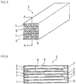
- the honeycomb structure 1 in the embodiment of the present invention has a configuration in which a plurality of cells 5 formed by porous partition walls 6 to become through channels of a fluid are arranged in parallel with one another along a central axis direction of the honeycomb structure 1.
- the configuration has a shape constituting a part of the whole structure, and the configurations are assembled in a direction perpendicular to the central axis of the honeycomb structure 1 to constitute the whole structure.
- the honeycomb structure has a constitution of a joined honeycomb segment body 10 obtained by integrally joining a plurality of honeycomb segments 2 each having this shape via a joining material layer 9.
- a cross sectional shape of the whole honeycomb structure cut along a plane perpendicular to the central axis of the honeycomb structure 1 is a circular shape, an elliptic shape, a triangular shape, a square shape or another shape, and an outer peripheral surface is coated with a coating material 4.
- the honeycomb structure 1 is used as a DPF and this structure is disposed in an exhaust system of a diesel engine or the like, it is possible to collect particulates discharged from the diesel engine and including soot.
- each of the honeycomb segments 2 has a shape constituting a part of the whole honeycomb structure 1 (the joined honeycomb segment body 10), and also has such a shape that the honeycomb segments are assembled in the direction perpendicular to the central axis of the honeycomb structure 1 to constitute the whole structure (see Fig. 1 ).
- the cells 5 are arranged in parallel with one another along the central axis direction of the honeycomb structure 1, and ends of the adjacent cells 5 are alternately plugged with a filling material 7.
- a left end side in Figs. 3 and 4 is open, whereas a right end side is plugged with the filling material 7, and in the other cell 5 (the outflow cell) adjacent to this predetermined cell, a left end side is plugged with the filling material 7, but a right end side is open.
- end surfaces of the honeycomb segments 2 have a checkered pattern.
- Fig. 4 shows that the left side of the honeycomb segment 2 becomes an inlet of the exhaust gas.
- the exhaust gas flows into the honeycomb segment 2 through the cells 5 (the inflow cells) which are not plugged but are open.
- the exhaust gas which has flowed into the cells 5 (the inflow cells) passes through the porous partition walls 6 to flow out of the other adjacent cells 5 (the outflow cells).
- the particulates including the soot in the exhaust gas are collected by the partition walls 6. In this way, the exhaust gas can be purified. By such collection, the particulates including the soot are deposited in the honeycomb segment 2 with elapse of time, to increase a pressure loss.
- Figs. 2 to 4 show the honeycomb segment 2 having the square cross sectional shape of the whole segment, but the shape may be triangular, hexagonal or the like. Furthermore, the cross sectional shape of each of the cells 5 may be a triangular shape, a hexagonal shape, a circular shape, an elliptic shape or another shape.
- the plurality of honeycomb segments 2 are joined via the joining material layer 9.
- the outer peripheral surfaces of the honeycomb segments 2 are coated with a joining material to form the joining material layer 9, and the joining material layer 9 functions so as to join the honeycomb segments 2.
- a joining material composition to form the joining material layer 9 contains, as aggregates, essential components including inorganic particles, and acicular crystal particles having a shot content ratio smaller than 10 mass%.
- Examples of the inorganic particles for use as the aggregate of the joining material composition include silicon carbide (SiC), cordierite, alumina, zirconia, yttria, mullite, aluminum silicate, silicon, and a silicon-silicon carbide composite material.
- silicon carbide, cordierite, alumina, zirconia and yttria are preferable.
- An average particle diameter of the inorganic particles is preferably from 1 to 20 ⁇ m, and more preferably from 1.5 to 10 ⁇ m.
- the acicular crystal particles are similarly used.
- the acicular crystal particles mentioned in the present description conceptually include both “natural acicular minerals” and “inorganic fibers having a shot content ratio smaller than 10 mass%".
- the acicular crystal particles for use in the present invention include 80 mass% or more of acicular crystal particles having an average length of 20 to 500 ⁇ m in a long axis direction of the acicular crystal particles, and preferably 20 mass% or less of acicular crystal particles having an average length smaller than 20 ⁇ m.
- the acicular crystal particles further preferably include 90 mass% or more of the acicular crystal particles having the average length of 20 to 500 ⁇ m in the long axis direction of the acicular crystal particles.
- an average diameter of cross sections of the acicular crystal particles which are perpendicular to the long axis direction of the acicular crystal particles is preferably from 1 to 20 ⁇ m, and further preferably from 1.5 to 15 ⁇ m.
- the natural acicular minerals are acicular silicate minerals produced from the nature, excluding asbestos (serpentine and amphibole).
- examples of the natural acicular minerals include sepiolite, wollastonite, palygorskite and attapulgite. 80 mass% or more of the natural acicular minerals having an average length of 20 to 500 ⁇ m in a long axis direction of the natural acicular minerals are contained, and an average diameter of cross sections of the natural acicular minerals which are perpendicular to the long axis direction of the natural acicular minerals is preferably from 1 to 20 ⁇ m.
- the natural acicular minerals are used as one of the aggregates of the joining material composition, voids are generated in the joining material layer which joins the honeycomb segments, to decrease a Young's modulus of the joining material layer, thereby enabling stress relaxation by thermal expansion of the honeycomb segments.
- these actions are correlated, to enhance a stress relaxing function and a joining strength of the honeycomb structure obtained by joining the honeycomb segments, so that the honeycomb structure having an excellent resistance to heat shock can be obtained.
- Such noticeable enhancement of the strength of the joining material layer of the honeycomb segments cannot be obtained, when the inorganic fibers are simply used as a conventional aggregate.
- these natural acicular minerals do not include a grain-like substance (hereinafter referred to as "the shot") which is a non-fiber substance because an operation of melting an inorganic material to form fibers is not carried out. Therefore, problems such as deteriorations of the stress relaxing function and joining strength caused by the presence of the shot in the case of the use of the inorganic fibers do not occur. Also in this respect, the natural acicular minerals are further preferable.
- the inorganic fibers having a shot content ratio smaller than 10 mass% in addition to the natural acicular minerals, as one of the aggregates of the joining material composition.
- the inorganic fibers usually mean artificial amorphous fibers, and are obtained by blending a mineral, a mineral ore, a slag, a rock, inorganic powder and the like in various combinations, melting the blend, and carrying out blow-off by use of a centrifugal force or the like to obtain a fibrous state.
- Typical examples of the inorganic fibers include refractory ceramic fibers (RCF), glass wools (GW), rock wools (RW), and slag wools (SW).
- RCF refractory ceramic fibers
- GW glass wools
- RW rock wools
- SW slag wools
- a residual raw material which is not spun due to thread breakage or the like during refinement of the inorganic fibers or the like solidifies again, and the grain-like non-fiber substance is generated sometimes. It is known that this grain-like substance (the shot) is the byproduct of the inorganic fibers and that when this shot is included, the stress relaxing function and joining strength of the honeycomb
- the inorganic fibers are not preferable as the component of the joining material, because the shot is included and a performance of the honeycomb structure is accordingly adversely affected.
- the inorganic fibers when the shot content ratio is smaller than 10 mass%, the inorganic fibers can be used together with the above-mentioned natural acicular minerals, as the acicular crystal particles which are the aggregate of the joining material composition.
- the inorganic fibers having a small shot content ratio are further preferable, the inorganic fibers having a shot content ratio smaller than 5 mass% are more preferable, and the inorganic fibers which do not contain the shot are most preferable.
- the inorganic particles, and the acicular crystal particles having the shot content ratio smaller than 10 mass% there are used the inorganic particles, and the acicular crystal particles having the shot content ratio smaller than 10 mass%, but a blend ratio between the inorganic particles and the acicular crystal particles is preferably in a range of 10:90 to 90:10 in terms of mass ratio.
- mass ratio of the acicular crystal particles is smaller than 10
- the problems occur that the stress relaxing function and joining strength of the joining material run short and that a sufficient resistance to heat shock cannot be obtained.
- the mass ratio in excess of 90 when a paste-like joining material composition is prepared, fluidity runs short, and a coating defect easily takes place. Therefore, either mass ratio is not preferable.
- the joining material composition is blended with a pore former so as to make the joining material layer 9 porous, thereby enhancing the stress relaxing function.
- a pore former for the joining material include resin balloons, carbons, a water absorbing resin, and fly ash balloons.
- the resin balloons, the carbons and the water absorbing resin are preferable from the viewpoints that particle diameter fluctuation is comparatively little and that uniform pores can be formed in the joining material layer.
- One of these pore formers may be used alone, or two or more of the pore formers may be used.
- a content ratio of the pore former for the joining material is preferably from 1 to 10 mass% of a total amount of a slurry of the joining material composition, and further preferably from 3 to 7 mass%.
- the joining material layer has a constitution in which spherical pores are further uniformly distributed.
- the stress relaxation is suitably compatible with the joining strength.
- An average particle diameter of the pore former for the joining material is preferably from 10 to 70 ⁇ m, and further preferably from 20 to 60 ⁇ m.
- the joining material composition can further contain additives such as an organic binder and a dispersant.
- organic binder heretofore known organic binders can suitably be selected and used.
- dispersant heretofore known dispersants can suitably be selected and used.
- organic binder specifically, carboxymethylcellulose (CMC), methylcellulose, hydroxypropyl methylcellulose or the like can be used.
- CMC carboxymethylcellulose
- methylcellulose methylcellulose
- carboxymethylcellulose and methylcellulose are preferable. This is because joining properties of the joining material composition become suitable.
- An amount of the organic binder to be blended is preferably from 1 to 10 parts by mass, and further preferably from 3 to 6 parts by mass to 100 parts by mass of the aggregates. When the amount is in the above range, it is possible to form the joining material layer having a suitable joining strength.
- the coating of the joining surfaces of the honeycomb segments 2 with the joining material may be performed on the outer peripheral surfaces of the adjacent honeycomb segments, but the coating may be performed only to one of the corresponding outer peripheral surfaces between the adjacent honeycomb segments. This coating of the only one of the corresponding surfaces can preferably save an amount of the joining material to be used.
- a thickness of the joining material layer is determined in consideration of a joining force between the honeycomb segments, and is suitably selected from a range of, for example, 0.5 to 3.0 mm.
- an example of a material of the honeycomb segments 2 for use in the present invention is a material constituted of at least one selected from the group consisting of silicon carbide (SiC), a silicon-silicon carbide composite material formed by using silicon carbide (SiC) as an aggregate and using silicon (Si) as a binding agent, silicon nitride, cordierite, mullite, alumina, spinel, a silicon carbide-cordierite composite material, a silicon-silicon carbide composite material, lithium aluminum silicate, aluminum titanate, and Fe-Cr-Al metal.
- the material constituted of silicon carbide (SiC) or the silicon-silicon carbide composite material is preferable.
- Preparation of the honeycomb segment 2 can be performed, for example, by adding a binder such as methylcellulose, hydroxypropoxyl cellulose, hydroxyethylcellulose, carboxymethylcellulose or polyvinyl alcohol, a surfactant, water as a solvent and the like to the material suitably selected from the above-mentioned materials, to obtain a kneaded material having plasticity, extruding this kneaded material into the above-mentioned shape, and then drying the segment with microwaves, hot air or the like, followed by sintering.
- a binder such as methylcellulose, hydroxypropoxyl cellulose, hydroxyethylcellulose, carboxymethylcellulose or polyvinyl alcohol, a surfactant, water as a solvent and the like
- the filling material 7 for use in plugging the cells 5 a material similar to that of the honeycomb segment 2 can be used.
- the plugging with the filling material 7 can be performed by immersing the end surface of the honeycomb segment 2 into the slurry-like filling material 7 to fill the filling material into the open cells 5 while the cells 5 which are not to be plugged are masked.
- the filling of the filling material 7 may be performed prior to firing after the forming of the honeycomb segment 2, or after the firing. However, the filling is preferably performed prior to the firing, because the firing step ends for single step.
- the honeycomb structure of the present invention has the above constitution, and a compressive Young's modulus of the joining material layer 9 in a Z-axis direction of the layer is from 20 to 100 MPa, and preferably from 30 to 60 MPa.
- the compressive Young's modulus in the Z-axis direction was calculated as follows. That is, a sample having a predetermined dimension (from 10x10 mm to 30x30 mm, and a thickness of 0.5 to 3 mm) was cut out, and subjected to a compression test in the Z-axis direction. Moreover, the sample may be provided with a base material.
- the compressive Young's modulus of the joining material layer for use in the present embodiment in the Z-axis direction is smaller than 20 MPa and the segment has a temperature distribution in itself, the segment itself is noticeably deformed, and cracks are generated sometimes.
- the compressive Young's modulus is larger than 100 MPa, the segment itself does not have any problems.
- the stress cannot be relaxed, and an outer peripheral portion of the honeycomb structure is damaged sometimes due to heat stress rapidly generated during the regeneration treatment of the DPF.
- the joining strength in the joining material layer 9 of the honeycomb structure is from 500 to 1500 kPa, and preferably from 800 to 1200 kPa.
- honeycomb segment raw material SiC powder and metal Si powder were mixed at a mass ratio of 80:20, starch and resin balloons were added as pore formers to this mixture, and methylcellulose and hydroxypropoxyl methylcellulose, a surfactant and water were further added to prepare a kneaded material having plasticity.
- This kneaded material was extruded, and dried with microwaves and hot air, to obtain a formed honeycomb segment body having a partition wall thickness of 310 ⁇ m, a cell density of about 46.5 cells/cm 2 (300 cells/square inch), a regular tetragonal cross section with one side of 35 mm and a length of 152 mm.
- both end surfaces of cells were plugged so that the end surfaces had a checkered pattern. That is, the plugging was performed so that mutually opposite ends of the adjacent cells were closed.
- a plugging material a material similar to the honeycomb segment raw material was used. Both the end surfaces of the cells were plugged, dried, degreased at about 400°C in the atmospheric air, and then fired at about 1450°C in an Ar inactive atmosphere, to obtain the honeycomb segment including SiC crystal particles bound with Si and having a porous structure.
- inorganic particles of inorganic microparticle silicon carbide and acicular crystal particles of wollastonite were used, and as a pore former, resin balloons were used.
- the wollastonite of the acicular crystal particles was used in which an average length in a long axis direction of the particles and an average diameter of cross sections perpendicular to the long axis direction were variously changed.
- a blend ratio between the inorganic microparticle silicon carbide and the wollastonite was variously changed. This wollastonite was a natural mineral and had a shot content ratio of zero.
- colloidal silica as an inorganic binder, carboxymethylcellulose as an organic binder and polyethylene glycol oleate as a dispersant were added, and water was further added and mixed. Afterward, this mixture was kneaded in a mixer for 30 minutes to obtain a paste-like joining material composition. Then, water was added to regulate a viscosity of the paste-like joining material composition so that the viscosity was from 300 to 400 dPa ⁇ s. Sizes and a blend ratio of the inorganic microparticle silicon carbide and the wollastonite used here and a blend ratio and the like of the other added components are shown in Table 1.
- honeycomb segment An outer wall surface of the honeycomb segment was coated with various joining material compositions shown in Table 1 to form a joining material layer having a thickness of about 1 mm, and another honeycomb segment was mounted on the joining material layer. This step was repeated to prepare a laminated honeycomb segment body constituted of 16 honeycomb segments, and an external pressure was added, to join all the honeycomb segments. Afterward, the laminated honeycomb segment body was dried at 140°C for two hours to obtain a joined honeycomb segment body. Next, an outer periphery of the joined honeycomb segment body was cut into a cylindrical shape, coated with a coating material, and dried at 700°C for two hours to harden, thereby obtaining the honeycomb structure.
- honeycomb structures A part of each of the obtained honeycomb structures was cut and removed, and a compressive Young's modulus in a Z-axis direction and a joining strength of each of samples were measured. Furthermore, the respective honeycomb structures were subjected to a rapid heating test (the burner spalling test, B-sp), a rapid cooling test (the electric furnace spalling test, E-sp), and an engine test (the E/G test). These test results are shown in Table 2.
- the compressive Young's modulus and the joining strength were measured by the methods already described in the present description. Moreover, the rapid heating test (B-sp), the rapid cooling test (E-sp) and the engine test (the E/G test) were carried out as follows, respectively.
- honeycomb structure was heated by an electric furnace at 500°C for two hours to make a uniform temperature. Afterward, the honeycomb structure was removed from the electric furnace, and rapidly cooled down to room temperature. The resistance to heat shock was evaluated by judging whether or not the cracks of the honeycomb structure due to the rapid cooling were present.
- Example 1 200 3.0 0 54.1 0.3 1.0 6.0
- Example 2 150 6.0 0 28.3 0.8 0.8 4.0
- Example 3 100 15.0 0 28.3 0.6 0.8 2.0
- Example 4 200 10.0 0 77.4 0.6 0.6 4.0
- Example 5 300 0.6 0 30.6 0.4 1.0 1.0
- Example 6 200 25.0 0 50.4 0.3 1.0 2.0 Comparative Example 1 300 5.0 50 46.4 0.3 1.0 2.0 Comparative Example 2 10 3.0 0 29.2 0.4 1.0 2.0 *: The blend ratio of the acicular crystal particles of the aggregate component is shown.
- honeycomb structures of the examples of the present invention withstood a high temperature which was not lower than 800°C, and had a suitable resistance to heat shock. Moreover, in these honeycomb structures, any cracks were not generated in the E-sp test and the E/G test, and the honeycomb structures had the suitable resistance to heat shock. In particular, the honeycomb structures of Examples 1 to 5 had a further excellent resistance to heat shock.
- the honeycomb structure of Comparative Example 1 had a very large shot content ratio of 50 mass%, the cracks were generated in the honeycomb structure in the E-sp test, and hence the honeycomb structure had a poor resistance to heat shock.
- the honeycomb structure of Comparative Example 2 wollastonite of acicular crystal particles had a very small average length of 10 ⁇ m in a long axis direction. Therefore, a sufficient stress relaxing function was not obtained, a low temperature of 600°C resulted in the B-sp test, the cracks were generated in the honeycomb structure in the E-sp test and the E/G test, and the honeycomb structure had a poor resistance to heat shock.
- a honeycomb structure of the present invention is useful as a collecting filter of particulates, for example, a diesel particulate filter (DPF) to collect and remove the particulates included in an exhaust gas from a diesel engine or the like.
- DPF diesel particulate filter
Landscapes
- Chemical & Material Sciences (AREA)
- Engineering & Computer Science (AREA)
- Ceramic Engineering (AREA)
- Materials Engineering (AREA)
- Structural Engineering (AREA)
- Organic Chemistry (AREA)
- Manufacturing & Machinery (AREA)
- Chemical Kinetics & Catalysis (AREA)
- Geometry (AREA)
- Physics & Mathematics (AREA)
- Inorganic Chemistry (AREA)
- Composite Materials (AREA)
- Civil Engineering (AREA)
- Filtering Materials (AREA)
- Ceramic Products (AREA)
- Filtering Of Dispersed Particles In Gases (AREA)
- Porous Artificial Stone Or Porous Ceramic Products (AREA)
- Processes For Solid Components From Exhaust (AREA)
- Nanotechnology (AREA)
Claims (8)
- Wabenstruktur (1), die einen verbundenen Wabensegmentkörper (10) umfasst, in dem eine Vielzahl von Wabensegmenten (2) durch gemeinsame Verbindungsflächen über eine Verbindungsmaterialschicht (9) einstückig miteinander verbunden sind, und die eine Konfiguration aufweist, in der eine Vielzahl von Zellen (5), die zu Durchlasskanälen für ein Fluid werden, entlang einer Mittelachsenrichtung parallel zueinander angeordnet sind,
wobei die Verbindungsmaterialschicht (9) anorganische Partikel sowie nadelförmige Kristallpartikel als Aggregate umfasst, die einen Shot-Anteil von kleiner als 10 Masse-% aufweisen und wobei die nadelförmigen Kristallpartikel 80 Masse-% oder mehr von nadelförmigen Kristallpartikeln mit einer Durchschnittslänge von 20 bis 500 µm in Richtung einer Längsachse der nadelförmigen Kristallpartikel umfassen;
wobei die nadelförmigen Kristallpartikel zur Verwendung als das Aggregat in der Verbindungsmaterialschicht natürliche nadelförmige Mineralien sind. - Wabenstruktur (2) gemäß Anspruch 1, wobei die anorganischen Partikel zur Verwendung als das Aggregat in der Verbindungsmaterialschicht (9) anorganische Partikel von einem, zwei oder mehr ausgewählt aus der Gruppe bestehend aus Siliziumkarbid (SiC), Kordierit, Aluminiumoxid, Zirkonium und Yttriumoxid sind.
- Wabenstruktur (1) nach Anspruch 1 oder 2, wobei ein Durchschnittspartikeldurchmesser der anorganischen Partikel 1 bis 20 µm beträgt.
- Wabenstruktur (1) nach Anspruch 1, wobei die natürlichen nadelförmigen Mineralien nadelförmige Mineralien von einem, zwei oder mehr ausgewählt aus der Gruppe bestehend aus Sepiolit, Wollastonit, Palygorskit und Attapulgit sind.
- Wabenstruktur (1) nach einem der Ansprüche 1 bis 4, wobei der Durchschnittsdurchmesser von Querschnitten der nadelförmigen Kristallpartikel, die senkrecht zur Richtung der Längsachse der nadelförmigen natürlichen Mineralien angeordnet sind, 1 bis 20 µm beträgt.
- Wabenstruktur (1) nach einem der Ansprüche 1 bis 5, wobei das Verhältnis zwischen den anorganischen Partikeln und den nadelförmigen Kristallpartikeln in der Verbindungsmaterialschicht (9) im Bereich von 10:90 bis 90:10 in Bezug auf das Masseverhältnis liegt.
- Wabenstruktur (1) nach einem der Ansprüche 1 bis 6, wobei der E-Modul der Verbindungsmaterialschicht (9) im Bereich von 20 bis 100 MPa liegt.
- Wabenstruktur (1) nach einem der Ansprüche 1 bis 7, wobei eine Verbindungsfestigkeit der Verbindungsmaterialschicht (9) im Bereich 500 bis 1500 kPa liegt.
Applications Claiming Priority (1)
| Application Number | Priority Date | Filing Date | Title |
|---|---|---|---|
| JP2012072862A JP5844672B2 (ja) | 2012-03-28 | 2012-03-28 | ハニカム構造体 |
Publications (3)
| Publication Number | Publication Date |
|---|---|
| EP2644580A2 EP2644580A2 (de) | 2013-10-02 |
| EP2644580A3 EP2644580A3 (de) | 2013-10-16 |
| EP2644580B1 true EP2644580B1 (de) | 2016-09-07 |
Family
ID=48040011
Family Applications (1)
| Application Number | Title | Priority Date | Filing Date |
|---|---|---|---|
| EP13160980.2A Active EP2644580B1 (de) | 2012-03-28 | 2013-03-26 | Wabenstruktur |
Country Status (3)
| Country | Link |
|---|---|
| US (1) | US9138674B2 (de) |
| EP (1) | EP2644580B1 (de) |
| JP (1) | JP5844672B2 (de) |
Families Citing this family (19)
| Publication number | Priority date | Publication date | Assignee | Title |
|---|---|---|---|---|
| US10052792B2 (en) | 2011-03-17 | 2018-08-21 | Corning Incorporated | Method and system for control of an axial skinning apparatus |
| US9670809B2 (en) | 2011-11-29 | 2017-06-06 | Corning Incorporated | Apparatus and method for skinning articles |
| US9139479B2 (en) | 2012-02-24 | 2015-09-22 | Corning Incorporated | Honeycomb structure comprising a cement skin composition with crystalline inorganic fibrous material |
| JP6059954B2 (ja) * | 2012-10-30 | 2017-01-11 | 日本碍子株式会社 | ハニカムフィルタ |
| US9239296B2 (en) | 2014-03-18 | 2016-01-19 | Corning Incorporated | Skinning of ceramic honeycomb bodies |
| US10611051B2 (en) | 2013-10-15 | 2020-04-07 | Corning Incorporated | Systems and methods for skinning articles |
| JP6231910B2 (ja) * | 2014-03-14 | 2017-11-15 | 日本碍子株式会社 | 目封止ハニカム構造体 |
| JP6285234B2 (ja) * | 2014-03-25 | 2018-02-28 | 日本碍子株式会社 | ハニカム構造体の製造方法 |
| JP6077484B2 (ja) * | 2014-03-26 | 2017-02-08 | 日本碍子株式会社 | ハニカム構造体 |
| CN104018918B (zh) * | 2014-06-09 | 2016-08-17 | 盐城工学院 | 一种柴油机尾气净化装置及其制备方法 |
| JP6335823B2 (ja) | 2015-03-25 | 2018-05-30 | 日本碍子株式会社 | ハニカム構造体、及びハニカム構造体の製造方法 |
| JP6473365B2 (ja) * | 2015-03-31 | 2019-02-20 | 日本碍子株式会社 | セラミックスフィルタ |
| JP6622134B2 (ja) * | 2016-03-31 | 2019-12-18 | 日本碍子株式会社 | ハニカム構造体及びハニカム構造体の製造方法 |
| CN106076024A (zh) * | 2016-06-27 | 2016-11-09 | 安徽金联地矿科技有限公司 | 一种具有吸附功能的凹凸棒空气滤网 |
| US11305270B2 (en) * | 2016-08-26 | 2022-04-19 | N.E. Chemcat Corporation | Honeycomb structure, honeycomb structure type catalyst and production methods therefor |
| JP6847724B2 (ja) | 2017-03-21 | 2021-03-24 | 日本碍子株式会社 | 目封止ハニカム構造体 |
| CN114302764B (zh) * | 2019-09-11 | 2023-12-26 | 日本碍子株式会社 | 蜂窝结构体及尾气净化装置 |
| JP7313456B2 (ja) * | 2019-09-11 | 2023-07-24 | 日本碍子株式会社 | ハニカム構造体及び排気ガス浄化装置 |
| JP2025520337A (ja) * | 2022-06-09 | 2025-07-03 | ビーエーエスエフ モバイル エミッションズ カタリスツ エルエルシー | ガソリン微粒子フィルター |
Family Cites Families (19)
| Publication number | Priority date | Publication date | Assignee | Title |
|---|---|---|---|---|
| DK0816065T3 (da) | 1996-01-12 | 2004-03-22 | Ibiden Co Ltd | Keramisk struktur |
| EP1508356B1 (de) * | 1999-09-29 | 2006-12-13 | Ibiden Co., Ltd. | Wabenfömiger Filter und Anordnung von keramischen Filtern |
| JP3889194B2 (ja) | 2000-01-13 | 2007-03-07 | 日本碍子株式会社 | ハニカム構造体 |
| JP2002085922A (ja) * | 2000-09-20 | 2002-03-26 | Ibiden Co Ltd | セラミック構造体 |
| JP4392984B2 (ja) | 2000-12-11 | 2010-01-06 | イビデン株式会社 | セラミック構造体 |
| JP4167814B2 (ja) * | 2001-03-22 | 2008-10-22 | イビデン株式会社 | セラミックフィルタ集合体 |
| JP2004261623A (ja) * | 2003-01-08 | 2004-09-24 | Ngk Insulators Ltd | ハニカム構造体 |
| KR100668547B1 (ko) | 2004-05-18 | 2007-01-16 | 이비덴 가부시키가이샤 | 허니콤 구조체 및 배기 가스 정화 장치 |
| CN100453511C (zh) | 2005-03-28 | 2009-01-21 | 揖斐电株式会社 | 蜂窝结构体及密封材料 |
| JP4937116B2 (ja) | 2005-04-28 | 2012-05-23 | イビデン株式会社 | ハニカム構造体 |
| WO2006137155A1 (ja) * | 2005-06-24 | 2006-12-28 | Ibiden Co., Ltd. | ハニカム構造体 |
| KR20090020547A (ko) * | 2006-03-17 | 2009-02-26 | 니뽄 가이시 가부시키가이샤 | 허니컴 구조체 및 그것에 이용하는 접합재 |
| KR20090004935A (ko) | 2006-03-23 | 2009-01-12 | 니뽄 가이시 가부시키가이샤 | 허니컴 구조체 |
| FR2902424B1 (fr) | 2006-06-19 | 2008-10-17 | Saint Gobain Ct Recherches | Ciment de jointoiement a spheres creuses pour filtre a particules. |
| JP5060743B2 (ja) | 2006-06-30 | 2012-10-31 | 東京窯業株式会社 | SiC系接合材 |
| FR2937971B1 (fr) | 2008-10-30 | 2011-08-26 | Saint Gobain Ct Recherches | Corps assemble avec un ciment durci macroporeux |
| WO2011125225A1 (ja) * | 2010-04-09 | 2011-10-13 | イビデン株式会社 | ハニカム構造体及び排ガス浄化装置 |
| WO2011125227A1 (ja) * | 2010-04-09 | 2011-10-13 | イビデン株式会社 | ハニカム構造体及び排ガス浄化装置 |
| DE112012003075T5 (de) | 2011-07-22 | 2014-07-31 | Dow Global Technologies Llc | Verfahren zur Herstellung von zementierten und behäuteten nadelförmigen Mulltiwabenstrukturen |
-
2012
- 2012-03-28 JP JP2012072862A patent/JP5844672B2/ja active Active
-
2013
- 2013-03-21 US US13/848,313 patent/US9138674B2/en active Active
- 2013-03-26 EP EP13160980.2A patent/EP2644580B1/de active Active
Also Published As
| Publication number | Publication date |
|---|---|
| EP2644580A2 (de) | 2013-10-02 |
| JP2013203572A (ja) | 2013-10-07 |
| US9138674B2 (en) | 2015-09-22 |
| US20130255212A1 (en) | 2013-10-03 |
| EP2644580A3 (de) | 2013-10-16 |
| JP5844672B2 (ja) | 2016-01-20 |
Similar Documents
| Publication | Publication Date | Title |
|---|---|---|
| EP2644580B1 (de) | Wabenstruktur | |
| KR101066503B1 (ko) | 접합체, 접합재 조성물, 허니컴 세그먼트 접합체, 및 그것을 이용한 허니컴 구조체 | |
| EP2944366B1 (de) | Wabenstruktur | |
| KR101081638B1 (ko) | 접합체, 허니컴 세그먼트 접합체, 및 그것을 이용한 허니컴 구조체 | |
| US8039086B2 (en) | Bonding material, process for producing the same, and honeycomb structure made with the same | |
| EP2123617B1 (de) | Verbindungsmaterialzusammensetzung, verfahren zur herstellung der verbindungsmaterialzusammensetzung, verbundener gegenstand und verfahren zur herstellung des verbundenen gegenstands | |
| US8053054B2 (en) | Honeycomb structure | |
| JP4997068B2 (ja) | 接合体及びその製造方法 | |
| WO2013125713A1 (ja) | ハニカム構造体 | |
| JP4997064B2 (ja) | 接合材組成物及びその製造方法並びに接合体及びその製造方法 | |
| JPWO2008117611A1 (ja) | 接合材組成物及びその製造方法並びに接合体及びその製造方法 | |
| EP1860082B1 (de) | Wabenstruktur | |
| EP2090559B1 (de) | Wabenstrukturkörper | |
| JP7180669B2 (ja) | セラミックハニカムフィルタ |
Legal Events
| Date | Code | Title | Description |
|---|---|---|---|
| PUAL | Search report despatched |
Free format text: ORIGINAL CODE: 0009013 |
|
| PUAI | Public reference made under article 153(3) epc to a published international application that has entered the european phase |
Free format text: ORIGINAL CODE: 0009012 |
|
| AK | Designated contracting states |
Kind code of ref document: A2 Designated state(s): AL AT BE BG CH CY CZ DE DK EE ES FI FR GB GR HR HU IE IS IT LI LT LU LV MC MK MT NL NO PL PT RO RS SE SI SK SM TR |
|
| AX | Request for extension of the european patent |
Extension state: BA ME |
|
| AK | Designated contracting states |
Kind code of ref document: A3 Designated state(s): AL AT BE BG CH CY CZ DE DK EE ES FI FR GB GR HR HU IE IS IT LI LT LU LV MC MK MT NL NO PL PT RO RS SE SI SK SM TR |
|
| AX | Request for extension of the european patent |
Extension state: BA ME |
|
| RIC1 | Information provided on ipc code assigned before grant |
Ipc: C04B 37/00 20060101ALI20130911BHEP Ipc: C04B 35/505 20060101ALI20130911BHEP Ipc: C04B 35/486 20060101ALI20130911BHEP Ipc: C04B 35/565 20060101ALI20130911BHEP Ipc: C04B 28/24 20060101AFI20130911BHEP Ipc: C04B 35/195 20060101ALI20130911BHEP Ipc: C04B 35/111 20060101ALI20130911BHEP Ipc: C04B 38/00 20060101ALI20130911BHEP |
|
| 17P | Request for examination filed |
Effective date: 20140416 |
|
| RBV | Designated contracting states (corrected) |
Designated state(s): AL AT BE BG CH CY CZ DE DK EE ES FI FR GB GR HR HU IE IS IT LI LT LU LV MC MK MT NL NO PL PT RO RS SE SI SK SM TR |
|
| 17Q | First examination report despatched |
Effective date: 20140815 |
|
| GRAP | Despatch of communication of intention to grant a patent |
Free format text: ORIGINAL CODE: EPIDOSNIGR1 |
|
| INTG | Intention to grant announced |
Effective date: 20160315 |
|
| RIN1 | Information on inventor provided before grant (corrected) |
Inventor name: KODAMA, SUGURU Inventor name: SHIRAI, MASAHIRO Inventor name: TAKAHASHI, NOBUAKI Inventor name: UCHIDA, YASUSHI |
|
| GRAS | Grant fee paid |
Free format text: ORIGINAL CODE: EPIDOSNIGR3 |
|
| GRAA | (expected) grant |
Free format text: ORIGINAL CODE: 0009210 |
|
| AK | Designated contracting states |
Kind code of ref document: B1 Designated state(s): AL AT BE BG CH CY CZ DE DK EE ES FI FR GB GR HR HU IE IS IT LI LT LU LV MC MK MT NL NO PL PT RO RS SE SI SK SM TR |
|
| REG | Reference to a national code |
Ref country code: GB Ref legal event code: FG4D |
|
| REG | Reference to a national code |
Ref country code: CH Ref legal event code: EP |
|
| REG | Reference to a national code |
Ref country code: IE Ref legal event code: FG4D |
|
| REG | Reference to a national code |
Ref country code: AT Ref legal event code: REF Ref document number: 826684 Country of ref document: AT Kind code of ref document: T Effective date: 20161015 |
|
| REG | Reference to a national code |
Ref country code: DE Ref legal event code: R096 Ref document number: 602013011026 Country of ref document: DE |
|
| REG | Reference to a national code |
Ref country code: LT Ref legal event code: MG4D |
|
| REG | Reference to a national code |
Ref country code: NL Ref legal event code: MP Effective date: 20160907 |
|
| PG25 | Lapsed in a contracting state [announced via postgrant information from national office to epo] |
Ref country code: HR Free format text: LAPSE BECAUSE OF FAILURE TO SUBMIT A TRANSLATION OF THE DESCRIPTION OR TO PAY THE FEE WITHIN THE PRESCRIBED TIME-LIMIT Effective date: 20160907 Ref country code: LT Free format text: LAPSE BECAUSE OF FAILURE TO SUBMIT A TRANSLATION OF THE DESCRIPTION OR TO PAY THE FEE WITHIN THE PRESCRIBED TIME-LIMIT Effective date: 20160907 Ref country code: NO Free format text: LAPSE BECAUSE OF FAILURE TO SUBMIT A TRANSLATION OF THE DESCRIPTION OR TO PAY THE FEE WITHIN THE PRESCRIBED TIME-LIMIT Effective date: 20161207 Ref country code: FI Free format text: LAPSE BECAUSE OF FAILURE TO SUBMIT A TRANSLATION OF THE DESCRIPTION OR TO PAY THE FEE WITHIN THE PRESCRIBED TIME-LIMIT Effective date: 20160907 Ref country code: RS Free format text: LAPSE BECAUSE OF FAILURE TO SUBMIT A TRANSLATION OF THE DESCRIPTION OR TO PAY THE FEE WITHIN THE PRESCRIBED TIME-LIMIT Effective date: 20160907 |
|
| REG | Reference to a national code |
Ref country code: AT Ref legal event code: MK05 Ref document number: 826684 Country of ref document: AT Kind code of ref document: T Effective date: 20160907 |
|
| REG | Reference to a national code |
Ref country code: FR Ref legal event code: PLFP Year of fee payment: 5 |
|
| PG25 | Lapsed in a contracting state [announced via postgrant information from national office to epo] |
Ref country code: SE Free format text: LAPSE BECAUSE OF FAILURE TO SUBMIT A TRANSLATION OF THE DESCRIPTION OR TO PAY THE FEE WITHIN THE PRESCRIBED TIME-LIMIT Effective date: 20160907 Ref country code: GR Free format text: LAPSE BECAUSE OF FAILURE TO SUBMIT A TRANSLATION OF THE DESCRIPTION OR TO PAY THE FEE WITHIN THE PRESCRIBED TIME-LIMIT Effective date: 20161208 Ref country code: ES Free format text: LAPSE BECAUSE OF FAILURE TO SUBMIT A TRANSLATION OF THE DESCRIPTION OR TO PAY THE FEE WITHIN THE PRESCRIBED TIME-LIMIT Effective date: 20160907 Ref country code: NL Free format text: LAPSE BECAUSE OF FAILURE TO SUBMIT A TRANSLATION OF THE DESCRIPTION OR TO PAY THE FEE WITHIN THE PRESCRIBED TIME-LIMIT Effective date: 20160907 Ref country code: LV Free format text: LAPSE BECAUSE OF FAILURE TO SUBMIT A TRANSLATION OF THE DESCRIPTION OR TO PAY THE FEE WITHIN THE PRESCRIBED TIME-LIMIT Effective date: 20160907 |
|
| PG25 | Lapsed in a contracting state [announced via postgrant information from national office to epo] |
Ref country code: RO Free format text: LAPSE BECAUSE OF FAILURE TO SUBMIT A TRANSLATION OF THE DESCRIPTION OR TO PAY THE FEE WITHIN THE PRESCRIBED TIME-LIMIT Effective date: 20160907 Ref country code: EE Free format text: LAPSE BECAUSE OF FAILURE TO SUBMIT A TRANSLATION OF THE DESCRIPTION OR TO PAY THE FEE WITHIN THE PRESCRIBED TIME-LIMIT Effective date: 20160907 |
|
| PG25 | Lapsed in a contracting state [announced via postgrant information from national office to epo] |
Ref country code: PT Free format text: LAPSE BECAUSE OF FAILURE TO SUBMIT A TRANSLATION OF THE DESCRIPTION OR TO PAY THE FEE WITHIN THE PRESCRIBED TIME-LIMIT Effective date: 20170109 Ref country code: IS Free format text: LAPSE BECAUSE OF FAILURE TO SUBMIT A TRANSLATION OF THE DESCRIPTION OR TO PAY THE FEE WITHIN THE PRESCRIBED TIME-LIMIT Effective date: 20170107 Ref country code: BG Free format text: LAPSE BECAUSE OF FAILURE TO SUBMIT A TRANSLATION OF THE DESCRIPTION OR TO PAY THE FEE WITHIN THE PRESCRIBED TIME-LIMIT Effective date: 20161207 Ref country code: PL Free format text: LAPSE BECAUSE OF FAILURE TO SUBMIT A TRANSLATION OF THE DESCRIPTION OR TO PAY THE FEE WITHIN THE PRESCRIBED TIME-LIMIT Effective date: 20160907 Ref country code: SK Free format text: LAPSE BECAUSE OF FAILURE TO SUBMIT A TRANSLATION OF THE DESCRIPTION OR TO PAY THE FEE WITHIN THE PRESCRIBED TIME-LIMIT Effective date: 20160907 Ref country code: SM Free format text: LAPSE BECAUSE OF FAILURE TO SUBMIT A TRANSLATION OF THE DESCRIPTION OR TO PAY THE FEE WITHIN THE PRESCRIBED TIME-LIMIT Effective date: 20160907 Ref country code: BE Free format text: LAPSE BECAUSE OF FAILURE TO SUBMIT A TRANSLATION OF THE DESCRIPTION OR TO PAY THE FEE WITHIN THE PRESCRIBED TIME-LIMIT Effective date: 20160907 Ref country code: CZ Free format text: LAPSE BECAUSE OF FAILURE TO SUBMIT A TRANSLATION OF THE DESCRIPTION OR TO PAY THE FEE WITHIN THE PRESCRIBED TIME-LIMIT Effective date: 20160907 Ref country code: AT Free format text: LAPSE BECAUSE OF FAILURE TO SUBMIT A TRANSLATION OF THE DESCRIPTION OR TO PAY THE FEE WITHIN THE PRESCRIBED TIME-LIMIT Effective date: 20160907 |
|
| REG | Reference to a national code |
Ref country code: DE Ref legal event code: R097 Ref document number: 602013011026 Country of ref document: DE |
|
| PG25 | Lapsed in a contracting state [announced via postgrant information from national office to epo] |
Ref country code: IT Free format text: LAPSE BECAUSE OF FAILURE TO SUBMIT A TRANSLATION OF THE DESCRIPTION OR TO PAY THE FEE WITHIN THE PRESCRIBED TIME-LIMIT Effective date: 20160907 |
|
| PLBE | No opposition filed within time limit |
Free format text: ORIGINAL CODE: 0009261 |
|
| STAA | Information on the status of an ep patent application or granted ep patent |
Free format text: STATUS: NO OPPOSITION FILED WITHIN TIME LIMIT |
|
| PG25 | Lapsed in a contracting state [announced via postgrant information from national office to epo] |
Ref country code: DK Free format text: LAPSE BECAUSE OF FAILURE TO SUBMIT A TRANSLATION OF THE DESCRIPTION OR TO PAY THE FEE WITHIN THE PRESCRIBED TIME-LIMIT Effective date: 20160907 |
|
| 26N | No opposition filed |
Effective date: 20170608 |
|
| PG25 | Lapsed in a contracting state [announced via postgrant information from national office to epo] |
Ref country code: SI Free format text: LAPSE BECAUSE OF FAILURE TO SUBMIT A TRANSLATION OF THE DESCRIPTION OR TO PAY THE FEE WITHIN THE PRESCRIBED TIME-LIMIT Effective date: 20160907 |
|
| REG | Reference to a national code |
Ref country code: CH Ref legal event code: PL |
|
| GBPC | Gb: european patent ceased through non-payment of renewal fee |
Effective date: 20170326 |
|
| PG25 | Lapsed in a contracting state [announced via postgrant information from national office to epo] |
Ref country code: MC Free format text: LAPSE BECAUSE OF FAILURE TO SUBMIT A TRANSLATION OF THE DESCRIPTION OR TO PAY THE FEE WITHIN THE PRESCRIBED TIME-LIMIT Effective date: 20160907 |
|
| REG | Reference to a national code |
Ref country code: IE Ref legal event code: MM4A |
|
| PG25 | Lapsed in a contracting state [announced via postgrant information from national office to epo] |
Ref country code: LU Free format text: LAPSE BECAUSE OF NON-PAYMENT OF DUE FEES Effective date: 20170326 |
|
| REG | Reference to a national code |
Ref country code: FR Ref legal event code: PLFP Year of fee payment: 6 |
|
| PG25 | Lapsed in a contracting state [announced via postgrant information from national office to epo] |
Ref country code: GB Free format text: LAPSE BECAUSE OF NON-PAYMENT OF DUE FEES Effective date: 20170326 Ref country code: CH Free format text: LAPSE BECAUSE OF NON-PAYMENT OF DUE FEES Effective date: 20170331 Ref country code: LI Free format text: LAPSE BECAUSE OF NON-PAYMENT OF DUE FEES Effective date: 20170331 Ref country code: IE Free format text: LAPSE BECAUSE OF NON-PAYMENT OF DUE FEES Effective date: 20170326 |
|
| PG25 | Lapsed in a contracting state [announced via postgrant information from national office to epo] |
Ref country code: MT Free format text: LAPSE BECAUSE OF NON-PAYMENT OF DUE FEES Effective date: 20170326 |
|
| PG25 | Lapsed in a contracting state [announced via postgrant information from national office to epo] |
Ref country code: AL Free format text: LAPSE BECAUSE OF FAILURE TO SUBMIT A TRANSLATION OF THE DESCRIPTION OR TO PAY THE FEE WITHIN THE PRESCRIBED TIME-LIMIT Effective date: 20160907 |
|
| PG25 | Lapsed in a contracting state [announced via postgrant information from national office to epo] |
Ref country code: HU Free format text: LAPSE BECAUSE OF FAILURE TO SUBMIT A TRANSLATION OF THE DESCRIPTION OR TO PAY THE FEE WITHIN THE PRESCRIBED TIME-LIMIT; INVALID AB INITIO Effective date: 20130326 |
|
| PG25 | Lapsed in a contracting state [announced via postgrant information from national office to epo] |
Ref country code: CY Free format text: LAPSE BECAUSE OF NON-PAYMENT OF DUE FEES Effective date: 20160907 |
|
| PG25 | Lapsed in a contracting state [announced via postgrant information from national office to epo] |
Ref country code: MK Free format text: LAPSE BECAUSE OF FAILURE TO SUBMIT A TRANSLATION OF THE DESCRIPTION OR TO PAY THE FEE WITHIN THE PRESCRIBED TIME-LIMIT Effective date: 20160907 |
|
| PG25 | Lapsed in a contracting state [announced via postgrant information from national office to epo] |
Ref country code: TR Free format text: LAPSE BECAUSE OF FAILURE TO SUBMIT A TRANSLATION OF THE DESCRIPTION OR TO PAY THE FEE WITHIN THE PRESCRIBED TIME-LIMIT Effective date: 20160907 |
|
| PGFP | Annual fee paid to national office [announced via postgrant information from national office to epo] |
Ref country code: FR Payment date: 20200214 Year of fee payment: 8 |
|
| PG25 | Lapsed in a contracting state [announced via postgrant information from national office to epo] |
Ref country code: FR Free format text: LAPSE BECAUSE OF NON-PAYMENT OF DUE FEES Effective date: 20210331 |
|
| PGFP | Annual fee paid to national office [announced via postgrant information from national office to epo] |
Ref country code: DE Payment date: 20250128 Year of fee payment: 13 |