WO2021049094A1 - ハニカム構造体及び排気ガス浄化装置 - Google Patents
ハニカム構造体及び排気ガス浄化装置 Download PDFInfo
- Publication number
- WO2021049094A1 WO2021049094A1 PCT/JP2020/018451 JP2020018451W WO2021049094A1 WO 2021049094 A1 WO2021049094 A1 WO 2021049094A1 JP 2020018451 W JP2020018451 W JP 2020018451W WO 2021049094 A1 WO2021049094 A1 WO 2021049094A1
- Authority
- WO
- WIPO (PCT)
- Prior art keywords
- honeycomb structure
- outer peripheral
- honeycomb
- magnetic particles
- peripheral wall
- Prior art date
Links
Images


Classifications
-
- F—MECHANICAL ENGINEERING; LIGHTING; HEATING; WEAPONS; BLASTING
- F01—MACHINES OR ENGINES IN GENERAL; ENGINE PLANTS IN GENERAL; STEAM ENGINES
- F01N—GAS-FLOW SILENCERS OR EXHAUST APPARATUS FOR MACHINES OR ENGINES IN GENERAL; GAS-FLOW SILENCERS OR EXHAUST APPARATUS FOR INTERNAL COMBUSTION ENGINES
- F01N3/00—Exhaust or silencing apparatus having means for purifying, rendering innocuous, or otherwise treating exhaust
- F01N3/02—Exhaust or silencing apparatus having means for purifying, rendering innocuous, or otherwise treating exhaust for cooling, or for removing solid constituents of, exhaust
- F01N3/021—Exhaust or silencing apparatus having means for purifying, rendering innocuous, or otherwise treating exhaust for cooling, or for removing solid constituents of, exhaust by means of filters
- F01N3/022—Exhaust or silencing apparatus having means for purifying, rendering innocuous, or otherwise treating exhaust for cooling, or for removing solid constituents of, exhaust by means of filters characterised by specially adapted filtering structure, e.g. honeycomb, mesh or fibrous
- F01N3/0222—Exhaust or silencing apparatus having means for purifying, rendering innocuous, or otherwise treating exhaust for cooling, or for removing solid constituents of, exhaust by means of filters characterised by specially adapted filtering structure, e.g. honeycomb, mesh or fibrous the structure being monolithic, e.g. honeycombs
-
- F—MECHANICAL ENGINEERING; LIGHTING; HEATING; WEAPONS; BLASTING
- F01—MACHINES OR ENGINES IN GENERAL; ENGINE PLANTS IN GENERAL; STEAM ENGINES
- F01N—GAS-FLOW SILENCERS OR EXHAUST APPARATUS FOR MACHINES OR ENGINES IN GENERAL; GAS-FLOW SILENCERS OR EXHAUST APPARATUS FOR INTERNAL COMBUSTION ENGINES
- F01N9/00—Electrical control of exhaust gas treating apparatus
-
- B—PERFORMING OPERATIONS; TRANSPORTING
- B01—PHYSICAL OR CHEMICAL PROCESSES OR APPARATUS IN GENERAL
- B01D—SEPARATION
- B01D39/00—Filtering material for liquid or gaseous fluids
- B01D39/14—Other self-supporting filtering material ; Other filtering material
- B01D39/20—Other self-supporting filtering material ; Other filtering material of inorganic material, e.g. asbestos paper, metallic filtering material of non-woven wires
-
- B—PERFORMING OPERATIONS; TRANSPORTING
- B01—PHYSICAL OR CHEMICAL PROCESSES OR APPARATUS IN GENERAL
- B01D—SEPARATION
- B01D46/00—Filters or filtering processes specially modified for separating dispersed particles from gases or vapours
-
- B—PERFORMING OPERATIONS; TRANSPORTING
- B01—PHYSICAL OR CHEMICAL PROCESSES OR APPARATUS IN GENERAL
- B01D—SEPARATION
- B01D53/00—Separation of gases or vapours; Recovering vapours of volatile solvents from gases; Chemical or biological purification of waste gases, e.g. engine exhaust gases, smoke, fumes, flue gases, aerosols
- B01D53/34—Chemical or biological purification of waste gases
- B01D53/92—Chemical or biological purification of waste gases of engine exhaust gases
- B01D53/94—Chemical or biological purification of waste gases of engine exhaust gases by catalytic processes
-
- B—PERFORMING OPERATIONS; TRANSPORTING
- B01—PHYSICAL OR CHEMICAL PROCESSES OR APPARATUS IN GENERAL
- B01D—SEPARATION
- B01D53/00—Separation of gases or vapours; Recovering vapours of volatile solvents from gases; Chemical or biological purification of waste gases, e.g. engine exhaust gases, smoke, fumes, flue gases, aerosols
- B01D53/34—Chemical or biological purification of waste gases
- B01D53/96—Regeneration, reactivation or recycling of reactants
-
- C—CHEMISTRY; METALLURGY
- C04—CEMENTS; CONCRETE; ARTIFICIAL STONE; CERAMICS; REFRACTORIES
- C04B—LIME, MAGNESIA; SLAG; CEMENTS; COMPOSITIONS THEREOF, e.g. MORTARS, CONCRETE OR LIKE BUILDING MATERIALS; ARTIFICIAL STONE; CERAMICS; REFRACTORIES; TREATMENT OF NATURAL STONE
- C04B37/00—Joining burned ceramic articles with other burned ceramic articles or other articles by heating
-
- C—CHEMISTRY; METALLURGY
- C04—CEMENTS; CONCRETE; ARTIFICIAL STONE; CERAMICS; REFRACTORIES
- C04B—LIME, MAGNESIA; SLAG; CEMENTS; COMPOSITIONS THEREOF, e.g. MORTARS, CONCRETE OR LIKE BUILDING MATERIALS; ARTIFICIAL STONE; CERAMICS; REFRACTORIES; TREATMENT OF NATURAL STONE
- C04B38/00—Porous mortars, concrete, artificial stone or ceramic ware; Preparation thereof
-
- C—CHEMISTRY; METALLURGY
- C04—CEMENTS; CONCRETE; ARTIFICIAL STONE; CERAMICS; REFRACTORIES
- C04B—LIME, MAGNESIA; SLAG; CEMENTS; COMPOSITIONS THEREOF, e.g. MORTARS, CONCRETE OR LIKE BUILDING MATERIALS; ARTIFICIAL STONE; CERAMICS; REFRACTORIES; TREATMENT OF NATURAL STONE
- C04B41/00—After-treatment of mortars, concrete, artificial stone or ceramics; Treatment of natural stone
- C04B41/80—After-treatment of mortars, concrete, artificial stone or ceramics; Treatment of natural stone of only ceramics
- C04B41/81—Coating or impregnation
- C04B41/85—Coating or impregnation with inorganic materials
-
- F—MECHANICAL ENGINEERING; LIGHTING; HEATING; WEAPONS; BLASTING
- F01—MACHINES OR ENGINES IN GENERAL; ENGINE PLANTS IN GENERAL; STEAM ENGINES
- F01N—GAS-FLOW SILENCERS OR EXHAUST APPARATUS FOR MACHINES OR ENGINES IN GENERAL; GAS-FLOW SILENCERS OR EXHAUST APPARATUS FOR INTERNAL COMBUSTION ENGINES
- F01N3/00—Exhaust or silencing apparatus having means for purifying, rendering innocuous, or otherwise treating exhaust
- F01N3/02—Exhaust or silencing apparatus having means for purifying, rendering innocuous, or otherwise treating exhaust for cooling, or for removing solid constituents of, exhaust
- F01N3/021—Exhaust or silencing apparatus having means for purifying, rendering innocuous, or otherwise treating exhaust for cooling, or for removing solid constituents of, exhaust by means of filters
- F01N3/022—Exhaust or silencing apparatus having means for purifying, rendering innocuous, or otherwise treating exhaust for cooling, or for removing solid constituents of, exhaust by means of filters characterised by specially adapted filtering structure, e.g. honeycomb, mesh or fibrous
- F01N3/0224—Exhaust or silencing apparatus having means for purifying, rendering innocuous, or otherwise treating exhaust for cooling, or for removing solid constituents of, exhaust by means of filters characterised by specially adapted filtering structure, e.g. honeycomb, mesh or fibrous the structure being granular
-
- F—MECHANICAL ENGINEERING; LIGHTING; HEATING; WEAPONS; BLASTING
- F01—MACHINES OR ENGINES IN GENERAL; ENGINE PLANTS IN GENERAL; STEAM ENGINES
- F01N—GAS-FLOW SILENCERS OR EXHAUST APPARATUS FOR MACHINES OR ENGINES IN GENERAL; GAS-FLOW SILENCERS OR EXHAUST APPARATUS FOR INTERNAL COMBUSTION ENGINES
- F01N3/00—Exhaust or silencing apparatus having means for purifying, rendering innocuous, or otherwise treating exhaust
- F01N3/02—Exhaust or silencing apparatus having means for purifying, rendering innocuous, or otherwise treating exhaust for cooling, or for removing solid constituents of, exhaust
- F01N3/021—Exhaust or silencing apparatus having means for purifying, rendering innocuous, or otherwise treating exhaust for cooling, or for removing solid constituents of, exhaust by means of filters
- F01N3/023—Exhaust or silencing apparatus having means for purifying, rendering innocuous, or otherwise treating exhaust for cooling, or for removing solid constituents of, exhaust by means of filters using means for regenerating the filters, e.g. by burning trapped particles
- F01N3/027—Exhaust or silencing apparatus having means for purifying, rendering innocuous, or otherwise treating exhaust for cooling, or for removing solid constituents of, exhaust by means of filters using means for regenerating the filters, e.g. by burning trapped particles using electric or magnetic heating means
-
- F—MECHANICAL ENGINEERING; LIGHTING; HEATING; WEAPONS; BLASTING
- F01—MACHINES OR ENGINES IN GENERAL; ENGINE PLANTS IN GENERAL; STEAM ENGINES
- F01N—GAS-FLOW SILENCERS OR EXHAUST APPARATUS FOR MACHINES OR ENGINES IN GENERAL; GAS-FLOW SILENCERS OR EXHAUST APPARATUS FOR INTERNAL COMBUSTION ENGINES
- F01N3/00—Exhaust or silencing apparatus having means for purifying, rendering innocuous, or otherwise treating exhaust
- F01N3/08—Exhaust or silencing apparatus having means for purifying, rendering innocuous, or otherwise treating exhaust for rendering innocuous
- F01N3/10—Exhaust or silencing apparatus having means for purifying, rendering innocuous, or otherwise treating exhaust for rendering innocuous by thermal or catalytic conversion of noxious components of exhaust
- F01N3/18—Exhaust or silencing apparatus having means for purifying, rendering innocuous, or otherwise treating exhaust for rendering innocuous by thermal or catalytic conversion of noxious components of exhaust characterised by methods of operation; Control
- F01N3/20—Exhaust or silencing apparatus having means for purifying, rendering innocuous, or otherwise treating exhaust for rendering innocuous by thermal or catalytic conversion of noxious components of exhaust characterised by methods of operation; Control specially adapted for catalytic conversion ; Methods of operation or control of catalytic converters
-
- F—MECHANICAL ENGINEERING; LIGHTING; HEATING; WEAPONS; BLASTING
- F01—MACHINES OR ENGINES IN GENERAL; ENGINE PLANTS IN GENERAL; STEAM ENGINES
- F01N—GAS-FLOW SILENCERS OR EXHAUST APPARATUS FOR MACHINES OR ENGINES IN GENERAL; GAS-FLOW SILENCERS OR EXHAUST APPARATUS FOR INTERNAL COMBUSTION ENGINES
- F01N3/00—Exhaust or silencing apparatus having means for purifying, rendering innocuous, or otherwise treating exhaust
- F01N3/08—Exhaust or silencing apparatus having means for purifying, rendering innocuous, or otherwise treating exhaust for rendering innocuous
- F01N3/10—Exhaust or silencing apparatus having means for purifying, rendering innocuous, or otherwise treating exhaust for rendering innocuous by thermal or catalytic conversion of noxious components of exhaust
- F01N3/24—Exhaust or silencing apparatus having means for purifying, rendering innocuous, or otherwise treating exhaust for rendering innocuous by thermal or catalytic conversion of noxious components of exhaust characterised by constructional aspects of converting apparatus
- F01N3/28—Construction of catalytic reactors
-
- F—MECHANICAL ENGINEERING; LIGHTING; HEATING; WEAPONS; BLASTING
- F01—MACHINES OR ENGINES IN GENERAL; ENGINE PLANTS IN GENERAL; STEAM ENGINES
- F01N—GAS-FLOW SILENCERS OR EXHAUST APPARATUS FOR MACHINES OR ENGINES IN GENERAL; GAS-FLOW SILENCERS OR EXHAUST APPARATUS FOR INTERNAL COMBUSTION ENGINES
- F01N2240/00—Combination or association of two or more different exhaust treating devices, or of at least one such device with an auxiliary device, not covered by indexing codes F01N2230/00 or F01N2250/00, one of the devices being
- F01N2240/16—Combination or association of two or more different exhaust treating devices, or of at least one such device with an auxiliary device, not covered by indexing codes F01N2230/00 or F01N2250/00, one of the devices being an electric heater, i.e. a resistance heater
-
- F—MECHANICAL ENGINEERING; LIGHTING; HEATING; WEAPONS; BLASTING
- F01—MACHINES OR ENGINES IN GENERAL; ENGINE PLANTS IN GENERAL; STEAM ENGINES
- F01N—GAS-FLOW SILENCERS OR EXHAUST APPARATUS FOR MACHINES OR ENGINES IN GENERAL; GAS-FLOW SILENCERS OR EXHAUST APPARATUS FOR INTERNAL COMBUSTION ENGINES
- F01N2330/00—Structure of catalyst support or particle filter
- F01N2330/02—Metallic plates or honeycombs, e.g. superposed or rolled-up corrugated or otherwise deformed sheet metal
-
- F—MECHANICAL ENGINEERING; LIGHTING; HEATING; WEAPONS; BLASTING
- F01—MACHINES OR ENGINES IN GENERAL; ENGINE PLANTS IN GENERAL; STEAM ENGINES
- F01N—GAS-FLOW SILENCERS OR EXHAUST APPARATUS FOR MACHINES OR ENGINES IN GENERAL; GAS-FLOW SILENCERS OR EXHAUST APPARATUS FOR INTERNAL COMBUSTION ENGINES
- F01N2330/00—Structure of catalyst support or particle filter
- F01N2330/06—Ceramic, e.g. monoliths
-
- F—MECHANICAL ENGINEERING; LIGHTING; HEATING; WEAPONS; BLASTING
- F01—MACHINES OR ENGINES IN GENERAL; ENGINE PLANTS IN GENERAL; STEAM ENGINES
- F01N—GAS-FLOW SILENCERS OR EXHAUST APPARATUS FOR MACHINES OR ENGINES IN GENERAL; GAS-FLOW SILENCERS OR EXHAUST APPARATUS FOR INTERNAL COMBUSTION ENGINES
- F01N2330/00—Structure of catalyst support or particle filter
- F01N2330/08—Granular material
-
- F—MECHANICAL ENGINEERING; LIGHTING; HEATING; WEAPONS; BLASTING
- F01—MACHINES OR ENGINES IN GENERAL; ENGINE PLANTS IN GENERAL; STEAM ENGINES
- F01N—GAS-FLOW SILENCERS OR EXHAUST APPARATUS FOR MACHINES OR ENGINES IN GENERAL; GAS-FLOW SILENCERS OR EXHAUST APPARATUS FOR INTERNAL COMBUSTION ENGINES
- F01N2370/00—Selection of materials for exhaust purification
- F01N2370/22—Selection of materials for exhaust purification used in non-catalytic purification apparatus
- F01N2370/30—Materials having magnetic properties
-
- Y—GENERAL TAGGING OF NEW TECHNOLOGICAL DEVELOPMENTS; GENERAL TAGGING OF CROSS-SECTIONAL TECHNOLOGIES SPANNING OVER SEVERAL SECTIONS OF THE IPC; TECHNICAL SUBJECTS COVERED BY FORMER USPC CROSS-REFERENCE ART COLLECTIONS [XRACs] AND DIGESTS
- Y02—TECHNOLOGIES OR APPLICATIONS FOR MITIGATION OR ADAPTATION AGAINST CLIMATE CHANGE
- Y02T—CLIMATE CHANGE MITIGATION TECHNOLOGIES RELATED TO TRANSPORTATION
- Y02T10/00—Road transport of goods or passengers
- Y02T10/10—Internal combustion engine [ICE] based vehicles
- Y02T10/40—Engine management systems
Definitions
- the present invention relates to a honeycomb structure and an exhaust gas purification device.
- Automobile exhaust gas usually contains harmful components such as carbon monoxide, hydrocarbons and nitrogen oxides and fine particles such as carbon as a result of incomplete combustion. From the viewpoint of reducing health hazards to the human body, there is an increasing demand for reduction of harmful gas components and fine particles in automobile exhaust gas.
- Patent Document 1 proposes a technique of inserting a magnetic wire into a part of cells of a cordierite honeycomb widely used as a catalyst carrier honeycomb. According to this technique, a current can be passed through the coil on the outer periphery of the honeycomb to raise the wire temperature by induction heating, and the heat can raise the honeycomb temperature.
- Patent Document 1 when the magnetic wire is inserted into a part of the cell of the honeycomb structure, the cell into which the magnetic wire is inserted sacrifices the flow path for flowing the exhaust gas, so that the pressure is increased accordingly. There is a problem that the loss increases.
- the present invention can satisfactorily suppress pressure loss, and can remove combustion of carbon fine particles and the like by induction heating, or heat a catalyst to be supported on the honeycomb structure, and exhaust gas.
- the subject is to provide a gas purification device.
- the bonding material constituting the bonding material layer is a magnetic material. It has been found that the above-mentioned problems can be solved by adopting a structure containing particles. That is, the present invention is specified as follows. (1) A columnar honeycomb structure in which a plurality of columnar honeycomb segments are joined via a bonding material layer.
- the columnar honeycomb segment comprises an outer peripheral wall and a porous partition wall that is disposed inside the outer peripheral wall and partitions a plurality of cells that penetrate from one end face to the other end face to form a flow path.
- a columnar column having an outer peripheral wall and a porous partition wall arranged inside the outer peripheral wall and partitioning a plurality of cells forming a flow path from one end face to the other end face. It is a honeycomb structure
- the columnar honeycomb structure further includes a coat layer on the surface of the outer peripheral wall.
- the coating material constituting the coat layer is a honeycomb structure containing magnetic particles.
- honeycomb structure and an exhaust gas purifying device capable of satisfactorily suppressing pressure loss, removing combustion of carbon fine particles and the like by induction heating, or heating a catalyst to be supported on the honeycomb structure.
- (A) is a schematic appearance diagram of a columnar honeycomb structure according to still another embodiment of the present invention.
- (B) is a schematic cross-sectional view perpendicular to the axial direction of the honeycomb structure of (A). It is sectional drawing parallel to the axial direction of the honeycomb structure of still another embodiment of this invention. It is the schematic of the exhaust gas flow path of the exhaust gas purification apparatus which incorporated the honeycomb structure of one Embodiment of this invention. It is a graph which shows the heating test result of the honeycomb structure which concerns on Example. It is sectional drawing which is parallel to the axial direction of the honeycomb structure of one Embodiment of this invention. It is sectional drawing which is parallel to the axial direction of the honeycomb structure of one Embodiment of this invention. It is sectional drawing which is perpendicular to the axial direction of the honeycomb structure of one Embodiment of this invention.
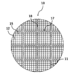
- FIG. 1 shows a schematic external view of the columnar honeycomb structure 10 according to the embodiment of the present invention.
- FIG. 2 shows a schematic cross-sectional view of the honeycomb structure 10 perpendicular to the axial direction.
- the honeycomb structure 10 is configured by joining a plurality of columnar honeycomb segments 17 via a bonding material layer 18.
- the honeycomb segment 17 includes an outer peripheral wall 11 and a porous partition wall 12 that is disposed inside the outer peripheral wall 11 and partitions a plurality of cells 15 that penetrate from one end face to the other end face to form a flow path.
- the outer shape of the honeycomb structure 10 is not particularly limited, but has a cylindrical end face (cylindrical shape), an oval-shaped columnar end face, and a polygonal end face (quadrangle, pentagon, hexagon, heptagon, octagon, etc.). It can have a columnar shape or the like.
- the size of the honeycomb structure 10 is not particularly limited, but the length in the central axial direction is preferably 40 to 500 mm. Further, for example, when the outer shape of the honeycomb structure 10 is columnar, the radius of the end face thereof is preferably 50 to 500 mm.
- the outer diameter of the honeycomb structure 10 may be the same as or different from the outer diameter of the honeycomb segment 17.
- a plurality of columnar honeycomb segments 17 having a quadrangular end face may be joined via a bonding material layer 18 to form a columnar honeycomb structure 10 having a quadrangular end face.
- a plurality of columnar honeycomb segments 17 having a quadrangular end face are joined via a joining material layer 18 to form a joined body having a quadrangular end face as a whole, and then the outer periphery of the joined body is ground to form an end face.
- the material of the partition wall 12 and the outer peripheral wall 11 of the honeycomb segment 17 is not particularly limited, but is usually formed of a ceramic material because it needs to be a porous body having a large number of pores.
- a ceramic material for example, cordierite, silicon carbide, silicon, aluminum titanate, silicon nitride, mullite, alumina, silicon-silicon carbide composites, silicon carbide-corgerite composites, especially silicon-silicon carbide composites or silicon carbide.
- Examples thereof include a sintered body as a main component.
- the term "silicon carbide-based" means that the honeycomb segment 17 contains silicon carbide in an amount of 50% by mass or more of the entire honeycomb segment 17.
- honeycomb segment 17 contains the silicon-silicon carbide composite as the main component means that the honeycomb segment 17 contains the silicon-silicon carbide composite (total mass) in an amount of 90% by mass or more of the entire honeycomb segment 17.
- the silicon-silicon carbide composite material contains silicon carbide particles as an aggregate and silicon as a binder for binding the silicon carbide particles, and a plurality of silicon carbide particles are formed between the silicon carbide particles. It is preferably bonded by silicon so as to form pores.
- the fact that the honeycomb segment 17 contains silicon carbide as a main component means that the honeycomb segment 17 contains silicon carbide (total mass) in an amount of 90% by mass or more of the entire honeycomb segment 17.
- the honeycomb segment 17 is more preferably having a high thermal conductivity from the viewpoint of heating the inside of the segment in a short time.
- the material for this purpose is preferably formed of at least one ceramic material selected from the group consisting of silicon carbide, silicon, and silicon nitride.
- the thermal conductivity of the ceramic material of the honeycomb segment 17 is preferably 3 W / mK or more, and more preferably 10 W / mK or more.
- the honeycomb segment 17 has a value of the coefficient of thermal expansion of the ceramic material as the coefficient of thermal expansion of the magnetic particles from the viewpoint of suppressing the thermal stress generated due to the difference in the coefficient of thermal expansion between the ceramic material and the magnetic particles during heating. Closer is more preferable.
- the material for this purpose is preferably formed of at least one selected from the group consisting of silicon carbide, silicon, and silicon nitride, and a ceramic material such as mullite and alumina.
- the coefficient of thermal expansion of the ceramic material of the honeycomb segment 17 is preferably 3 ⁇ 10 -6 or more. This coefficient of thermal expansion is measured with a thermal expansion meter, for example, in the range of room temperature to 800 ° C.
- the shape of the cell 15 of the honeycomb segment 17 is not particularly limited, but the cross section orthogonal to the central axis of the honeycomb segment 17 should be a polygon such as a triangle, a quadrangle, a pentagon, a hexagon, an octagon, a circle, or an ellipse. Is preferable, and other irregular shapes may be used.
- the thickness of the partition wall 12 of the honeycomb segment 17 is preferably 0.10 to 0.50 mm, and more preferably 0.25 to 0.45 mm in terms of ease of manufacture. For example, when it is 0.20 mm or more, the strength of the honeycomb structure 10 is further improved, and when it is 0.50 mm or less, the pressure loss can be further reduced when the honeycomb structure 10 is used as a filter. ..
- the thickness of the partition wall 12 is an average value measured by a method of observing a cross section in the central axis direction with a microscope.
- the porosity of the partition wall 12 constituting the honeycomb segment 17 is preferably 30 to 70%, and more preferably 40 to 65% in terms of ease of production.
- the porosity of the partition wall 12 is 30% or more, the pressure loss is likely to decrease, and when it is 70% or less, the strength of the honeycomb structure 10 can be maintained.
- the average pore diameter of the porous partition wall 12 is preferably 5 to 30 ⁇ m, more preferably 10 to 25 ⁇ m. When it is 5 ⁇ m or more, the pressure loss can be reduced when it is used as a filter, and when it is 30 ⁇ m or less, the strength of the honeycomb structure 10 can be maintained.
- the terms "average pore diameter” and “porosity” mean the average pore diameter and porosity measured by the mercury intrusion method.
- the cell density of the honeycomb segment 17 is preferably in the range of 5 to 93 cells / cm 2 , more preferably in the range of 5 to 63 cells / cm 2 , and in the range of 31 to 54 cells / cm 2. Is even more preferable.
- the cell density of the honeycomb segment 17 is 5 cells / cm 2 or more, the pressure loss is likely to decrease, and when it is 93 cells / cm 2 or less, the strength of the honeycomb structure 10 can be maintained.
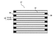
- the honeycomb segments 17 are alternately arranged with a plurality of cells A having one end face side open and having a mesh sealing portion 38 on the other end face, and cells A, respectively, and the other end face side is open.
- a plurality of cells B having a mesh sealing portion 39 on one end surface may be provided.
- the cells A and B are alternately arranged adjacent to each other with the partition wall 12 in between, and both end surfaces form a checkered pattern.
- the number, arrangement, shape, etc. of cells A and B are not limited, and can be appropriately designed as needed.
- Such a honeycomb structure 10 can be used as a filter (honeycomb filter) for purifying exhaust gas. When the honeycomb structure 10 is not used as a honeycomb filter, it is not necessary to provide the sealing portions 38 and 39.
- the honeycomb structure 10 of the present embodiment may have a catalyst supported on the surface of the partition wall 12 and / or in the pores of the partition wall 12.
- the type of catalyst is not particularly limited, and can be appropriately selected depending on the purpose and use of the honeycomb structure 10.
- a noble metal catalyst or a catalyst other than these can be mentioned.
- a noble metal catalyst such as platinum (Pt), palladium (Pd), or rhodium (Rh) is supported on the surface of the alumina pores, and a three-way catalyst containing a co-catalyst such as ceria or zirconia, an oxidation catalyst, or an alkali.
- a NO x storage reduction catalyst LNT catalyst
- earth metal and platinum as storage components of nitrogen oxide (NO x).
- catalysts that do not use noble metals include NO x selective reduction catalysts (SCR catalysts) containing copper-substituted or iron-substituted zeolites. Further, two or more kinds of catalysts selected from the group consisting of these catalysts may be used.
- the method of supporting the catalyst is also not particularly limited, and can be carried out according to the conventional method of supporting the catalyst on the honeycomb structure.
- the honeycomb structure 10 may have a breathable surface layer on at least a part of the surface of the partition wall 12.
- having breathability means that the permeability of the surface layer is 1.0 ⁇ 10 -13 m 2 or more. From the viewpoint of further reducing the pressure loss, the permeability is preferably 1.0 ⁇ 10 -12 m 2 or more. Since the surface layer has air permeability, it is possible to suppress the pressure loss of the honeycomb structure 10 caused by the surface layer.
- permability refers to a physical characteristic value calculated by the following formula (1), and is a value that is an index indicating the passing resistance when a predetermined gas passes through the object (partition wall 12). is there.
- C permeability (m 2 )
- F gas flow rate (cm 3 / s)
- T sample thickness (cm)
- V gas viscosity (dynes ⁇ sec / cm 2 ).
- D is the sample diameter (cm)
- P is the gas pressure (PSI).
- the partition wall 12 with the surface layer is cut out, the permeability is measured with the surface layer attached, and then the permability is measured with the surface layer scraped off, and the surface layer and the partition wall are measured.
- the permeability of the surface layer is calculated from the ratio of the thickness of the base material and the measurement results of these permeability.
- the porosity of the surface layer is preferably 50% or more, more preferably 60% or more, and even more preferably 70% or more. By having a porosity of 50% or more, pressure loss can be suppressed. However, if the porosity is too high, the surface layer becomes brittle and easily peels off, so it is preferably 90% or less.
- the difference between the mercury porosity of the sample having the surface layer and the base material and the mercury porosity of the base material only by scraping and removing only the surface layer is the difference between the surface layer. It is regarded as a mercury porosity curve, and the porosity of the surface layer is calculated from the scraped mass and the mercury porosity curve. SEM imaging may be performed, and the porosity of the surface layer may be calculated from the area ratio of the void portion and the solid portion by image analysis of the surface layer portion.
- the average pore diameter of the surface layer is preferably 10 ⁇ m or less, more preferably 5 ⁇ m or less, further preferably 4 ⁇ m or less, and particularly preferably 3 ⁇ m or less.
- the average pore diameter is preferably 10 ⁇ m or less, more preferably 5 ⁇ m or less, further preferably 4 ⁇ m or less, and particularly preferably 3 ⁇ m or less.
- the mercury porosi curve pore volume frequency
- the peak is taken as the average pore diameter.
- an SEM image of the cross section of the honeycomb structure 10 is taken, and the void portion and the solid portion are binarized by image analysis of the surface layer portion, 20 or more voids are randomly selected, and the average of the inscribed circles thereof is selected. May be the average pore diameter.
- the thickness of the surface layer is not particularly limited. However, in order to obtain the effect of the surface layer more remarkably, the thickness of the surface layer is preferably 10 ⁇ m or more. On the other hand, from the viewpoint of avoiding an increase in pressure loss, the thickness of the surface layer is preferably 80 ⁇ m or less. The thickness of the surface layer is more preferably 50 ⁇ m or less.
- the honeycomb structure 10 on which the surface layer is formed is cut in a direction perpendicular to the direction in which the cell 15 extends, and the thickness of the surface layer is measured from the cross section thereof. The average of the measured values of the thickness of the points can be taken.
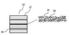
- FIG. 4 is a schematic cross-sectional view of the honeycomb structure 10 parallel to the axial direction.
- the bonding material constituting the bonding material layer 18 contains magnetic particles 21.
- an electric current is passed through the coil on the outer periphery of the honeycomb to raise the temperature of the magnetic particles 21 by induction heating, and the heat can raise the honeycomb temperature.
- the honeycomb structure 10 contains the magnetic particles 21 as a constituent component of the bonding material in the bonding material layer 18 instead of in the cell 15, it does not affect the pressure loss.
- the joining material constituting the joining material layer 18 for joining a plurality of honeycomb segments 17 may contain an aggregate 22, and at least a part of the aggregate 22 may be composed of magnetic particles 21. According to such a configuration, the magnetic material can be provided on the bonding material layer without increasing the volume of the bonding material layer, and the manufacturing efficiency is improved. Further, it is preferable that 40 to 100% by volume of the aggregate 22 is composed of magnetic particles 21, and more preferably 60 to 100% by volume of the aggregate. When the amount of the magnetic particles is 40 to 100% by volume, the contribution to the eddy current loss can be sufficiently obtained, and better heating characteristics can be obtained.
- the aggregate 22 is a ceramic containing at least one selected from the group consisting of cordierite, mullite, zircon, aluminum titanate, silicon carbide, silicon nitride, zirconia, spinel, indialite, sapphirine, corundum, and titania. It is preferable, and it is more preferable that the material is the same as that of the honeycomb segment 17. Silicon carbide is used as an aggregate because the conductive material contributes to the heating characteristics due to eddy current loss and the difference from magnetic particles in thermal expansion is relatively small. More preferable.
- the joining material constituting the joining material layer 18 preferably contains an inorganic binder in order to bond the aggregates to each other.
- an inorganic binder colloidal particles such as colloidal silica and colloidal alumina are preferably used.
- the bonding material constituting the bonding material layer 18 includes, for example, a dispersion medium (for example, water, etc.), and, if necessary, an inorganic binder, an organic binder, and a glutinating agent, in addition to the aggregate 22 containing the magnetic particles 21.
- a dispersion medium for example, water, etc.
- an inorganic binder for example, an organic binder, and a glutinating agent, in addition to the aggregate 22 containing the magnetic particles 21.
- Prepared by mixing additives such as foamed resin can be used.
- the addition of ceramic fibers is effective in imparting a stress relaxation function, and alumina fibers, magnesium silicate fibers and the like are preferably used from the viewpoint of complying with the REACH regulation.
- the organic binder include polyvinyl alcohol, methyl cellulose, CMC (carboxymethyl cellulose) and the like.
- the bonding material layer 18 of the honeycomb structure 10 is provided between all the adjacent honeycomb segments 17, and it is preferable that all the bonding material layers 18 include magnetic particles 21. According to such a configuration, the induction heating efficiency of the honeycomb structure 10 becomes better. Further, it is not necessary for all the bonding material layers 18 between the adjacent honeycomb segments 17 to contain the magnetic particles 21, and the bonding material layers 18 can be appropriately designed according to the desired induction heating efficiency.
- the bonding material layer 18 of the honeycomb structure 10 is provided along the axial direction of the honeycomb structure 10, but the aggregate 22 containing the magnetic material particles 21 is provided in the axial direction of the honeycomb structure 10. , It may be provided in the whole, or it may be provided in a part of the area.
- the aggregate 22 containing the magnetic particles 21 is provided on the entire axial direction of the honeycomb segment 17, the induction heating efficiency of the honeycomb segment 17 becomes better.
- the aggregate 22 containing the magnetic particles 21 is provided in a part of the region of the honeycomb segment 17 in the axial direction, for example, when the aggregate 22 is provided in the region on the inlet side of the gas flow path of the honeycomb segment 17, it is provided at the start position of the gas flow.
- the entire honeycomb segment 17 can be efficiently heated. Further, since soot tends to accumulate on the outlet side of the gas flow path of the honeycomb segment 17, if the aggregate 22 containing the magnetic particles 21 is provided in the region on the outlet side, the soot accumulated in the honeycomb segment 17 can be more effectively collected. Can be removed. Further, when the aggregate 22 containing the magnetic particles 21 is provided in a part of the honeycomb segment 17 in the axial direction, a coil provided on the outer periphery of the honeycomb structure 10 when the honeycomb structure 10 is used as an exhaust gas purifying device. Can be made compact.
- the bonding material layer 18 of the honeycomb structure 10 is provided so that the magnetic particles 21 and the aggregate are evenly mixed, but the present invention is not limited to this. That is, as shown in FIG. 10, in the bonding material layer 18, the magnetic particles 21 and the aggregate 22 may be unevenly distributed on one side along the axial direction of the honeycomb structure 10.
- the content of the magnetic particles 21 is preferably 30 to 70% by volume with respect to the bonding material layer 18.
- the content of the magnetic particles 21 is 30% by volume or more with respect to the bonding material layer 18, the induction heating efficiency of the honeycomb structure 10 becomes better.
- the content of the magnetic particles 21 is 70% by volume or less with respect to the bonding material layer 18, the effects of bonding strength and stress relaxation are likely to be exhibited, which is preferable.
- the magnetic particles 21 preferably have a Curie point of 450 ° C. or higher.
- the magnetic particle 21 has a Curie point of 450 ° C. or higher, it is possible to heat the catalyst supported on the honeycomb structure 10, and of course, the PM (particulate matter) collected in the cell 15 can be heated. It becomes easy to remove the combustion and regenerate the honeycomb structure filter.
- the magnetic material having a curry point of 450 ° C. or higher include the balance Co-20% by mass Fe, the balance Co-25% by mass Ni-4% by mass Fe, the balance Fe-15 to 35% by mass Co, and the balance Fe-.
- the magnetic particles 21 preferably have an intrinsic resistance value of 20 ⁇ cm or more at 25 ° C. According to such a configuration, the amount of heat generated by induction heating can be further increased.
- Examples of the magnetic material having an intrinsic resistance value of 20 ⁇ cm or more at 25 ° C. include the balance Fe-18 mass% Cr, the balance Fe-13 mass% Cr-2 mass% Si, and the balance Fe-20 mass% Cr-2 mass.
- the magnetic particle 21 preferably has a maximum magnetic permeability of 1000 or more. According to such a configuration, when the honeycomb structure 10 is dielectrically heated, the temperature is raised in a short time to a temperature at which moisture evaporates (about 100 ° C.) and further to a temperature at which the catalyst is activated (about 300 ° C.). Can be raised.
- the magnetic material having a maximum magnetic permeability of 1000 or more include the balance Fe-10% by mass Si-5% by mass Al, 49% by mass Co-49% by mass Fe-2% by mass V, and the balance Fe-36% by mass. There are Ni, the balance Fe-45% by mass Ni, the balance Fe-35% by mass Cr, the balance Fe-18% by mass Cr, and the like.
- the magnetic particles 21 are magnetized by a magnetic field, and the state of magnetization changes depending on the strength of the magnetic field. This is represented by the "magnetization curve".
- the magnetization curve may have a magnetic field H on the horizontal axis and a magnetic flux density B on the vertical axis (BH curve).
- the state in which no magnetic field is applied to the magnetic material is called the degaussing state and is represented by the origin O.
- the degaussing state When a magnetic field is applied, the magnetic flux density increases from the origin O and a saturated curve is drawn. This curve is the "initial magnetization curve".
- the slope of the straight line connecting the point on the initial magnetization curve and the origin is the "permeability".
- Permeability is a measure of the ease of magnetization of a magnetic material in the sense that a magnetic field permeates it.
- the magnetic permeability near the origin where the magnetic field is small is the “initial magnetic permeability”
- the maximum magnetic permeability on the initial magnetization curve is the “maximum magnetic permeability”.
- the honeycomb structure 10 may be provided with a coat layer 32 on the outer peripheral surface.
- the material constituting the coat layer 32 is not particularly limited, and various known coating materials can be appropriately used.
- the coating material may further contain colloidal silica, an organic binder, clay and the like.
- the organic binder is preferably used in an amount of 0.05 to 0.5% by mass, more preferably 0.1 to 0.2% by mass.
- the clay is preferably used in an amount of 0.2 to 2.0% by mass, more preferably 0.4 to 0.8% by mass.
- the coating material constituting the coat layer 32 may contain magnetic particles 21. More preferably, the coating material is a bonding material containing magnetic particles. According to such a configuration, the induction heating efficiency of the honeycomb structure 10 becomes better.
- the bonding material used for the coating material constituting the coat layer 32 the same material as described above can be used as the bonding material constituting the bonding material layer 18.
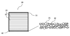
- FIG. 6A shows a schematic external view of the columnar honeycomb structure 20 according to another embodiment of the present invention.
- FIG. 6B shows a schematic cross-sectional view of the honeycomb structure 20 perpendicular to the axial direction.
- the honeycomb structure 20 is a porous partition wall 12 that is disposed inside the outer peripheral wall 11 and the outer peripheral wall 11 and partitions a plurality of cells 15 that penetrate from one end face to the other end face to form a flow path. And have.
- the honeycomb structure 20 further includes a coat layer 42 on the surface of the outer peripheral wall 11.
- the coating material constituting the coat layer 42 contains magnetic particles 21.
- the honeycomb structure 20 contains the magnetic particles 21 as a constituent component of the coating material in the coat layer 42, not in the cell 15, the pressure loss can be satisfactorily suppressed.
- FIG. 7 shows a schematic cross-sectional view of the honeycomb structure 20 parallel to the axial direction.
- the coating material constituting the coat layer 42 of the honeycomb structure 20 contains the aggregate 22 and at least a part of the aggregate 22 is similar to the bonding material of the bonding material layer 18 used in the honeycomb structure 10 described above. It may be composed of magnetic particles 21. Further, in the coat layer 42, the magnetic particles 21 may be uniformly distributed in the axial direction of the honeycomb structure 20, or may be provided in a part of the region of the honeycomb structure 20 in the axial direction. When the aggregate 22 containing the magnetic particles 21 is provided on the entire axial direction of the honeycomb structure 20, the heating efficiency of the honeycomb structure 20 by induction heating becomes better.
- the aggregate 22 containing the magnetic particles 21 is provided in a part of the region of the honeycomb structure 20 in the axial direction, for example, when the aggregate 22 is provided in the region on the inlet side of the gas flow path of the honeycomb structure 20, the gas flow starts. Since the gas heated at the position advances to the outlet side of the honeycomb structure 20, the entire honeycomb structure 20 can be efficiently heated. Further, since soot tends to accumulate on the outlet side of the gas flow path of the honeycomb structure 20, if the aggregate 22 containing the magnetic particles 21 is provided in the region on the outlet side, soot is more effectively accumulated in the honeycomb structure 20. Soot can be removed.
- the aggregate 22 containing the magnetic particles 21 is provided in a part of the honeycomb structure 20 in the axial direction, the aggregate 22 is provided on the outer periphery of the honeycomb structure 20 when the honeycomb structure 10 is used as an exhaust gas purifying device.
- the coil can be made compact. According to such a configuration, the magnetic material can be provided on the coat layer 42 without increasing the volume of the coat layer 42, and the production efficiency is improved.
- the coat layer 42 of the honeycomb structure 20 is provided so that the magnetic particles 21 and the aggregate are evenly mixed, but the coating layer 42 is not limited to this. That is, as shown in FIG. 11, in the coat layer 42, the magnetic particles 21 and the aggregate 22 may be unevenly distributed on one side along the axial direction of the honeycomb structure 20. As a result, when the honeycomb structure 20 is used as an exhaust gas purifying device, the coil provided on the outer periphery of the honeycomb structure 20 can be made compact.
- honeycomb structure manufacturing method The method for producing the honeycomb structure 10 according to the embodiment of the present invention will be described in detail.
- a honeycomb structure made of cordierite first, a cordierite-forming raw material is prepared as a material for clay. Since each component is blended in the cordierite-forming raw material so as to have the theoretical composition of the cordierite crystal, a silica source component, a magnesia source component, an alumina source component, and the like are blended. Of these, quartz and fused silica are preferably used as the silica source component, and the particle size of the silica source component is preferably 100 to 150 ⁇ m.
- magnesia source component examples include talc, magnesite and the like. Of these, talc is preferred. Talc is preferably contained in 37 to 43% by mass in the cordierite-forming raw material.
- the particle size (average particle size) of talc is preferably 5 to 50 ⁇ m, more preferably 10 to 40 ⁇ m.
- the magnesia (MgO) source component may contain Fe 2 O 3 , CaO, Na 2 O, K 2 O and the like as impurities.
- alumina source component those containing at least one of aluminum oxide and aluminum hydroxide are preferable in that there are few impurities.
- aluminum hydroxide is preferably contained in an amount of 10 to 30% by mass, and aluminum oxide is preferably contained in an amount of 0 to 20% by mass in the cordierite-forming raw material.
- a material (additive) for clay to be added to the cordierite raw material At least a binder and a pore-forming agent are used as additives. In addition to the binder and the pore-forming agent, a dispersant or a surfactant can be used.
- a substance that can be oxidized and removed by reacting with oxygen at a temperature equal to or lower than the firing temperature of cordierite, or a low melting point reactant having a melting point at a temperature equal to or lower than the firing temperature of corderite can be used.
- the substance that can be oxidatively removed include resins (particularly particulate resin) and graphite (particularly particulate graphite).
- the low melting point reactant at least one metal selected from the group consisting of iron, copper, zinc, lead, aluminum, and nickel, and alloys containing these metals as main components (for example, carbon steel in the case of iron). , Cast iron, stainless steel), or alloys containing two or more kinds of main components can be used.
- the low melting point reactant is preferably a powder-granular or fibrous iron alloy. Further, the particle size or fiber diameter (average diameter) is preferably 10 to 200 ⁇ m. Examples of the shape of the low melting point reactant include a spherical shape, a lozenge shape, a konpeito shape, and the like, and these shapes are preferable because the shape of the pores can be easily controlled.
- binder examples include hydroxypropylmethyl cellulose, methyl cellulose, hydroxyethyl cellulose, carboxymethyl cellulose, polyvinyl alcohol and the like.
- dispersant for example, dextrin, polyalcohol and the like can be mentioned.
- surfactant for example, fatty acid soap can be mentioned.
- the additive may be used alone or in combination of two or more.
- the prepared clay is molded into a honeycomb shape by an extrusion molding method, an injection molding method, a press molding method, etc. to obtain a raw honeycomb molded body. It is preferable to adopt an extrusion molding method because continuous molding is easy and, for example, cordierite crystals can be oriented.
- the extrusion molding method can be performed using an apparatus such as a vacuum clay kneader, a ram type extrusion molding machine, and a twin-screw type continuous extrusion molding machine.
- honeycomb molded body is dried and adjusted to a predetermined size to obtain a honeycomb dried body.
- the honeycomb molded body can be dried by hot air drying, microwave drying, dielectric drying, vacuum drying, vacuum drying, freeze drying and the like. Since the whole can be dried quickly and uniformly, it is preferable to perform drying by combining hot air drying and microwave drying or dielectric drying.
- honeycomb body is fired to produce a fired honeycomb body.
- each of the honeycomb fired bodies is used as a honeycomb segment, and the side surfaces of the plurality of honeycomb segments are joined and integrated by a joining material layer made of a joining material containing magnetic particles, and the plurality of honeycomb segments are joined.
- the honeycomb structure is in the state of being completed.
- the honeycomb structure in which the honeycomb segments are joined can be manufactured, for example, as follows.
- the bonding material is prepared by mixing, for example, a dispersion medium (for example, water, etc.) and, if necessary, additives such as a binder, a glue, and a foamed resin, in addition to the aggregate containing magnetic particles. can do.
- a dispersion medium for example, water, etc.
- additives such as a binder, a glue, and a foamed resin, in addition to the aggregate containing magnetic particles. can do.
- honeycomb segments are arranged adjacent to each other so that the side surfaces of the honeycomb segments face each other, and the adjacent honeycomb segments are crimped to each other and then heat-dried. In this way, a honeycomb structure in which the side surfaces of adjacent honeycomb segments are joined by a bonding material layer is produced.
- the material of the mask for preventing adhesion of the bonding material is not particularly limited, but for example, a synthetic resin such as polypropylene (PP), polyethylene terephthalate (PET), polyimide, or Teflon (registered trademark) can be preferably used.
- the mask preferably has an adhesive layer, and the material of the adhesive layer is preferably an acrylic resin, a rubber-based (for example, rubber containing natural rubber or synthetic rubber as a main component), or a silicon-based resin. preferable.
- an adhesive film having a thickness of 20 to 50 ⁇ m can be preferably used.
- the outer peripheral surface may be ground to remove the outer peripheral wall.
- a coating material is applied to the outer periphery of the honeycomb structure from which the outer peripheral wall has been removed in this manner in a later step to form a coat layer.
- a part of the outer peripheral wall may be ground and removed, and a coat layer may be formed on the portion by a coating material.
- FIG. 12 by impregnating the outer periphery of the honeycomb structure with magnetic particles as a slurry in a later step, the partition wall of the porous outer peripheral wall and the cell in the vicinity thereof can be obtained. The pores may be filled with magnetic particles.
- the honeycomb structure 30 in which the pores of the outer peripheral wall of the columnar honeycomb structure are filled with magnetic particles can be produced.
- the coating material when preparing the coating material, for example, it can be prepared using a biaxial rotary vertical mixer. Further, the coating material may further contain colloidal silica, an organic binder, clay and the like.
- the organic binder is preferably used in an amount of 0.05 to 0.5% by mass, more preferably 0.1 to 0.2% by mass. Further, the clay is preferably used in an amount of 0.2 to 2.0% by mass, more preferably 0.4 to 0.8% by mass.
- a coating material is applied to the outer peripheral surface of the honeycomb structure, and the applied coating material is dried to form a coat layer.
- the coating material is applied to the outer peripheral surface of the honeycomb structure, and the applied coating material is dried to form a coat layer.
- the honeycomb structure is placed on a turntable and rotated, and the coating material is discharged from the blade-shaped coating nozzle while the coating nozzle is applied along the outer peripheral portion of the honeycomb structure.
- a method of pressing and applying can be mentioned. With this configuration, the coating material can be applied with a uniform thickness. Further, the surface roughness of the formed outer peripheral coating is reduced, and it is possible to form an outer peripheral coating which is excellent in appearance and is not easily damaged by thermal shock.
- the method for drying the applied coating material is not particularly limited.
- the coating material is dried.
- a method for removing water and organic substances can be preferably used by holding the product in an electric furnace at 600 ° C. for 1 hour or longer.
- the catalyst When the catalyst is supported on the honeycomb structure, there is no particular limitation on the method of supporting the catalyst, and the catalyst can be supported according to the method of supporting the catalyst which is performed in the conventional method for producing the honeycomb structure.
- the exhaust gas purification device can be configured by using the honeycomb structure according to the embodiment of the present invention described above.
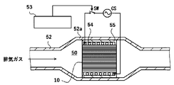
- FIG. 8 shows, as an example, a schematic view of the exhaust gas flow path of the exhaust gas purification device 50 in which the honeycomb structure 10 is incorporated.
- the exhaust gas purifying device 50 has a honeycomb structure 10 and a coil wiring 54 that spirally orbits the outer periphery of the honeycomb structure 10. Further, the exhaust gas purification device 50 has a metal pipe 52 for accommodating the honeycomb structure 10 and the coil wiring 54.
- the exhaust gas purification device 50 can be arranged in the enlarged diameter portion 52a of the metal pipe 52.
- the coil wiring 54 may be fixed in the metal tube 52 by the fixing member 55.
- the fixing member 55 is preferably a heat-resistant member such as a ceramic fiber.
- the honeycomb structure 10 may carry a catalyst.
- the coil wiring 54 is spirally wound around the outer circumference of the honeycomb structure 10. It is also assumed that two or more coil wirings 54 are used. An alternating current supplied from the alternating current power supply CS flows through the coil wiring 54 in response to the on (ON) of the switch SW, and as a result, a magnetic field that changes periodically is generated around the coil wiring 54.
- the on / off of the switch SW is controlled by the control unit 53.
- the control unit 53 can turn on the switch SW in synchronization with the start of the engine and allow an alternating current to flow through the coil wiring 54. It is also assumed that the control unit 53 turns on the switch SW regardless of the start of the engine (for example, in response to the operation of the heating switch pushed by the driver).
- the temperature of the honeycomb structure 10 rises according to a change in the magnetic field according to the alternating current flowing through the coil wiring 54. As a result, carbon fine particles and the like collected by the honeycomb structure 10 are burned.
- raising the temperature of the honeycomb structure 10 raises the temperature of the catalyst supported by the catalyst carrier contained in the honeycomb structure 10 and promotes the catalytic reaction.
- carbon monoxide (CO), oxide oxide (NO x ), and hydrocarbon (CH) are oxidized or reduced to carbon dioxide (CO 2 ), nitrogen (N 2 ), and water (H 2 O).
- Example 1 A columnar honeycomb segment made of cordierite having a square shape of 42 mm, a length of 85 mm, a partition wall thickness of 0.1 mm, and a distance between partition walls of about 1 mm was prepared. Next, a magnetic powder having an average particle size of 8 ⁇ m (composition: balance Fe-17 mass% Co-2 mass% Cr-1 mass% Mo) and silicon carbide powder having an average particle size of 6 ⁇ m were added at a mass ratio of 2: 1. After mixing, colloidal silica, alumina fiber having an average length of 200 ⁇ m, carboxymethyl cellulose, and water were further mixed to prepare a bonding material. The honeycomb segments were bonded with this bonding material to obtain a bonded body.
- a magnetic powder having an average particle size of 8 ⁇ m composition: balance Fe-17 mass% Co-2 mass% Cr-1 mass% Mo
- silicon carbide powder having an average particle size of 6 ⁇ m were added at a mass ratio of 2: 1.
- the outer circumference of the obtained bonded body was processed so as to have a cylindrical shape with a diameter of 82 mm to obtain a honeycomb structure.
- a heating test of the honeycomb structure was performed with an induction heating coil having a diameter of 100 mm, and the temperature of the end face of the honeycomb structure was measured with an infrared thermometer.
- the input power was 14 kW, the induction heating frequency was 30 kHz, and the temperature rising performance of the honeycomb structure was measured.
- FIG. 9 shows a graph showing the relationship between time (seconds) and temperature (° C.).
Abstract
圧力損失を良好に抑制することができ、誘導加熱によるカーボン微粒子などの燃焼除去または、ハニカム構造体に担持させる触媒の加熱が可能なハニカム構造体及び排気ガス浄化装置を提供する。柱状のハニカムセグメントが、接合材層を介して複数個接合して構成されている柱状のハニカム構造体であって、柱状のハニカムセグメントは、外周壁と、外周壁の内側に配設され、一方の端面から他方の端面まで貫通して流路を形成する複数のセルを区画形成する多孔質の隔壁とを有し、接合材層を構成する接合材が、磁性体粒子を含むハニカム構造体。
Description
本発明は、ハニカム構造体及び排気ガス浄化装置に関する。
自動車の排気ガスには、通常は不完全燃焼の結果として一酸化炭素、炭化水素、窒素酸化物などの有害成分やカーボンなどの微粒子が含まれる。人体への健康被害低減の観点から、自動車排気ガス中の有害ガス成分および微粒子の低減要求が高まっている。
しかしながら、現在、これらの有害成分は、特に、エンジン始動直後という、触媒温度が低く、触媒活性が不十分な期間に排出されている。このため、排気ガス中の有害成分が、触媒活性化温度に達する前に触媒で浄化されずに排出されるおそれがある。このような要求に応えるためには、触媒活性化温度に達する前に触媒で浄化されずに排出されるエミッションを極力低減させることが必要であり、例えば、誘導加熱技術を利用した対策が知られている。
このような技術として、特許文献1には、触媒担体ハニカムとして広く使用されているコージェライトハニカムの一部のセルに、磁性体ワイヤーを挿入する技術が提案されている。当該技術によれば、ハニカム外周のコイルに電流を流し、誘導加熱によりワイヤー温度を上昇させ、その熱でハニカム温度を上昇させることができる。
しかしながら、特許文献1のように、ハニカム構造体のセルの一部に磁性体ワイヤーを挿入すると、磁性体ワイヤーが挿入されたセルは排気ガスを流すための流路が犠牲となるため、それだけ圧力損失が増加するという問題がある。
本発明は、このような事情に鑑み、圧力損失を良好に抑制することができ、誘導加熱によるカーボン微粒子などの燃焼除去または、ハニカム構造体に担持させる触媒の加熱が可能なハニカム構造体及び排気ガス浄化装置を提供することを課題とするものである。
本発明者らは鋭意検討の結果、柱状のハニカムセグメントが、接合材層を介して複数個接合して構成されている柱状のハニカム構造体において、接合材層を構成する接合材が、磁性体粒子を含む構成とすることで、上記課題を解決できることを見出した。すなわち、本発明は以下のように特定される。
(1)柱状のハニカムセグメントが、接合材層を介して複数個接合して構成されている柱状のハニカム構造体であって、
前記柱状のハニカムセグメントは、外周壁と、前記外周壁の内側に配設され、一方の端面から他方の端面まで貫通して流路を形成する複数のセルを区画形成する多孔質の隔壁とを有し、
前記接合材層を構成する接合材が、磁性体粒子を含むハニカム構造体。
(2)外周壁と、前記外周壁の内側に配設され、一方の端面から他方の端面まで貫通して流路を形成する複数のセルを区画形成する多孔質の隔壁と、を有する柱状のハニカム構造体であって、
前記柱状のハニカム構造体が、更に外周壁の表面にコート層を備え、
前記コート層を構成するコーティング材が、磁性体粒子を含むハニカム構造体。
(3)多孔質の外周壁と、前記外周壁の内側に配設され、一方の端面から他方の端面まで貫通して流路を形成する複数のセルを区画形成する多孔質の隔壁と、を有する柱状のハニカム構造体であって、
前記柱状のハニカム構造体の外周壁の気孔内に磁性体粒子が充填されているハニカム構造体。
(4)(1)~(3)のいずれかに記載のハニカム構造体と、
前記ハニカム構造体の外周を螺旋状に周回するコイル配線と、
前記ハニカム構造体及び前記コイル配線を収容する金属管と、
を有する排気ガス浄化装置。
圧力損失を良好に抑制することができ、誘導加熱によるカーボン微粒子などの燃焼除去または、ハニカム構造体に担持させる触媒の加熱が可能なハニカム構造体及び排気ガス浄化装置を提供することができる。
以下、図面を参照して、本発明のハニカム構造体の実施形態について説明するが、本発明は、これに限定されて解釈されるものではなく、本発明の範囲を逸脱しない限りにおいて、当業者の知識に基づいて、種々の変更、修正、改良を加え得るものである。
<1.ハニカム構造体>
図1に、本発明の一実施形態の柱状のハニカム構造体10の外観模式図を示す。図2に、ハニカム構造体10の軸方向と垂直な断面模式図を示す。ハニカム構造体10は、柱状のハニカムセグメント17が、接合材層18を介して複数個接合して構成されている。ハニカムセグメント17は、外周壁11と、外周壁11の内側に配設され、一方の端面から他方の端面まで貫通して流路を形成する複数のセル15を区画形成する多孔質の隔壁12とを有する。
図1に、本発明の一実施形態の柱状のハニカム構造体10の外観模式図を示す。図2に、ハニカム構造体10の軸方向と垂直な断面模式図を示す。ハニカム構造体10は、柱状のハニカムセグメント17が、接合材層18を介して複数個接合して構成されている。ハニカムセグメント17は、外周壁11と、外周壁11の内側に配設され、一方の端面から他方の端面まで貫通して流路を形成する複数のセル15を区画形成する多孔質の隔壁12とを有する。
ハニカム構造体10の外形は、特に限定されないが、端面が円形の柱状(円柱形状)、端面がオーバル形状の柱状、端面が多角形(四角形、五角形、六角形、七角形、八角形等)の柱状等の形状とすることができる。また、ハニカム構造体10の大きさは、特に限定されないが、中心軸方向長さが40~500mmが好ましい。また、例えば、ハニカム構造体10の外形が円柱状の場合、その端面の半径が50~500mmであることが好ましい。
ハニカム構造体10の外形は、ハニカムセグメント17の外径と同じであってもよく、異なっていてもよい。例えば、端面が四角形の柱状のハニカムセグメント17を、接合材層18を介して複数個接合することで、端面が同じく四角形の柱状のハニカム構造体10としてもよい。また、端面が四角形の柱状のハニカムセグメント17を、接合材層18を介して複数個接合して全体で端面が四角形の接合体を形成した後、当該接合体の外周を研削することで、端面が円形の柱状のハニカム構造体10としてもよい。
ハニカムセグメント17の隔壁12及び外周壁11の材質については特に制限はないが、多数の細孔を有する多孔質体であることが必要であるため、通常は、セラミックス材料で形成される。例えば、コージェライト、炭化珪素、珪素、チタン酸アルミニウム、窒化珪素、ムライト、アルミナ、珪素-炭化珪素系複合材料、炭化珪素-コージェライト系複合材料の、特に珪素-炭化珪素複合材又は炭化珪素を主成分とする焼結体が挙げられる。本明細書において「炭化珪素系」とは、ハニカムセグメント17が炭化珪素を、ハニカムセグメント17全体の50質量%以上含有していることを意味する。ハニカムセグメント17が珪素-炭化珪素複合材を主成分とするというのは、ハニカムセグメント17が珪素-炭化珪素複合材(合計質量)を、ハニカムセグメント17全体の90質量%以上含有していることを意味する。ここで、珪素-炭化珪素複合材は、骨材としての炭化珪素粒子、及び炭化珪素粒子を結合させる結合材としての珪素を含有するものであり、複数の炭化珪素粒子が、炭化珪素粒子間に細孔を形成するようにして、珪素によって結合されていることが好ましい。また、ハニカムセグメント17が炭化珪素を主成分とするというのは、ハニカムセグメント17が炭化珪素(合計質量)を、ハニカムセグメント17全体の90質量%以上含有していることを意味する。
ハニカムセグメント17は、セグメント内部まで短時間で加熱させる観点から、熱伝導率が高い方がより好ましい。このための材質としては、炭化珪素、珪素、及び、窒化珪素からなる群から選択される少なくとも1つのセラミックス材料で形成されるのが好ましい。ハニカムセグメント17のセラミックス材料の熱伝導率は、3W/mK以上であることが好ましく、10W/mK以上あることがより好ましい。
ハニカムセグメント17は、加熱の際にセラミックス材料と磁性体粒子との熱膨張係数の差異によって発生する熱応力を抑制する観点から、セラミックス材料の熱膨張係数が磁性体粒子の熱膨張係数に値が近い方がより好ましい。このための材質としては、炭化珪素、珪素、及び、窒化珪素からなる群から選択される少なくとも1つ、ムライト、アルミナ等のセラミックス材料で形成されるのが好ましい。ハニカムセグメント17のセラミックス材料の熱膨張係数は、3×10⁻⁶以上あることが好ましい。この熱膨張係数は、例えば室温から800℃の範囲で、熱膨張計にて測定される。
ハニカムセグメント17のセル15の形状は特に限定されないが、ハニカムセグメント17の中心軸に直交する断面において、三角形、四角形、五角形、六角形、八角形等の多角形、円形、又は楕円形であることが好ましく、その他不定形であってもよい。
ハニカムセグメント17の隔壁12の厚さは、0.10~0.50mmであることが好ましく、製造の容易さの点で、0.25~0.45mmであることが更に好ましい。例えば、0.20mm以上であると、ハニカム構造体10の強度がより向上し、0.50mm以下であると、ハニカム構造体10をフィルタとして用いた場合に、圧力損失をより小さくすることができる。なお、この隔壁12の厚さは、中心軸方向断面を顕微鏡観察する方法で測定した平均値である。
また、ハニカムセグメント17を構成する隔壁12の気孔率は、30~70%であることが好ましく、製造の容易さの点で40~65%であることが更に好ましい。隔壁12の気孔率が30%以上であると、圧力損失が減少しやすく、70%以下であると、ハニカム構造体10の強度を維持できる。
また、多孔質の隔壁12の平均細孔径は、5~30μmであることが好ましく、10~25μmであることが更に好ましい。5μm以上であると、フィルタとして用いた場合に、圧力損失を小さくすることができ、30μm以下であると、ハニカム構造体10の強度を維持できる。なお、本明細書において、「平均細孔径」、「気孔率」というときには、水銀圧入法により測定した平均細孔径、気孔率を意味するものとする。
ハニカムセグメント17のセル密度は、5~93セル/cm2の範囲であることが好ましく、5~63セル/cm2の範囲であることがより好ましく、31~54セル/cm2の範囲であることが更に好ましい。ハニカムセグメント17のセル密度が5セル/cm2以上であると、圧力損失が減少しやすく、93セル/cm2以下であると、ハニカム構造体10の強度を維持できる。
図3に示すように、ハニカムセグメント17は、一方の端面側が開口して他方の端面に目封止部38を有する複数のセルAと、セルAとそれぞれ交互に配置され、他方の端面側が開口して一方の端面に目封止部39を有する複数のセルBとを備えてもよい。セルA及びセルBは隔壁12を挟んで交互に隣接配置されており、両端面は市松模様を形成する。セルA及びセルBの数、配置、形状等は制限されず、必要に応じて適宜設計することができる。このようなハニカム構造体10は、排気ガスを浄化するフィルタ(ハニカムフィルタ)として用いることができる。なお、ハニカム構造体10は、ハニカムフィルタとして用いない場合は、目封止部38、39を設けなくてもよい。
本実施形態のハニカム構造体10は、隔壁12の表面及び/又は隔壁12の細孔内に触媒が担持されたものであってもよい。
触媒の種類については特に制限はなく、ハニカム構造体10の使用目的や用途に応じて適宜選択することができる。例えば、貴金属系触媒又はこれら以外の触媒が挙げられる。貴金属系触媒としては、白金(Pt)、パラジウム(Pd)、ロジウム(Rh)といった貴金属をアルミナ細孔表面に担持し、セリア、ジルコニア等の助触媒を含む三元触媒や酸化触媒、又は、アルカリ土類金属と白金を窒素酸化物(NOx)の吸蔵成分として含むNOx吸蔵還元触媒(LNT触媒)が例示される。貴金属を用いない触媒として、銅置換又は鉄置換ゼオライトを含むNOx選択還元触媒(SCR触媒)等が例示される。また、これらの触媒からなる群から選択される2種以上の触媒を用いてもよい。なお、触媒の担持方法についても特に制限はなく、従来、ハニカム構造体に触媒を担持する担持方法に準じて行うことができる。
ハニカム構造体10は、隔壁12の表面の少なくとも一部において、通気性を有する表面層を有してもよい。ここで、通気性を有するとは、表面層のパーミアビリティーが、1.0×10⁻¹³m2以上であることをいう。圧力損失をさらに低減する観点から、パーミアビリティーが、1.0×10⁻¹²m2以上であることが好ましい。表面層が通気性を有することで、表面層に起因するハニカム構造体10の圧力損失を抑制することができる。
また、本明細書において「パーミアビリティー」は、下記式(1)により算出される物性値をいい、所定のガスがその物(隔壁12)を通過する際の通過抵抗を表す指標となる値である。ここで、下記式(1)中、Cはパーミアビリティー(m2)、Fはガス流量(cm3/s)、Tは試料厚み(cm)、Vはガス粘性(dynes・sec/cm2)、Dは試料直径(cm)、Pはガス圧力(PSI)を示す。なお、下記式(1)中の数値は、13.839(PSI)=1(atm)であり、68947.6(dynes・sec/cm2)=1(PSI)である。

表面層の気孔率は、50%以上であることが好ましく、60%以上がより好ましく、70%以上がさらに好ましい。50%以上の気孔率を有することで、圧力損失を抑えることができる。ただし、気孔率が高すぎると表面層が脆くなり、はがれやすくなるので、90%以下とすることが好ましい。
水銀圧入法により表面層の気孔率を測定する方法として、表面層と基材とを有するサンプルでの水銀ポロシカーブと、表面層のみを削って取り除いた基材のみの水銀ポロシカーブの差を表面層の水銀ポロシカーブとみなし、削りとった質量と水銀ポロシカーブとから表面層の気孔率が算出される。SEM画像撮影を行い、表面層部分の画像解析により、空隙部と個体部の面積比率から表面層の気孔率を算出しても良い。
また、表面層の平均細孔直径は、10μm以下であることが好ましく、5μm以下であることがより好ましく、4μm以下であることがさらに好ましく、3μm以下であることが特に好ましい。平均細孔直径を10μm以下とすることで、高い粒子捕集効率を達成することができる。ただし、表面層の平均細孔直径が小さすぎると圧力損失が増加してしまうので、0.5μm以上とすることが好ましい。
水銀圧入法により表面層の平均細孔直径を測定する方法として、水銀ポロシメータでのピーク値という形にして、表面層つきでの水銀ポロシカーブ(細孔容積頻度)と表面層のみを削って取り除いた基材のみの水銀ポロシカーブの差を表面層の水銀ポロシカーブとし、そのピークを平均細孔直径とする。また、ハニカム構造体10の断面のSEM画像を撮影し表面層部分の画像解析により、空隙部と個体部の2値化を行い、ランダムに20以上の空隙を選択してその内接円の平均を平均細孔直径としても良い。
また、表面層の厚みは特に限定されない。ただし、表面層の効果をより顕著に得るためには、表面層の厚みが10μm以上であることが好ましい。一方、圧力損失の増加を回避する観点から、表面層の厚みが80μm以下であることが好ましい。表面層の厚みはより好ましくは50μm以下である。表面層の厚みの測定方法として、例えば表面層が形成されたハニカム構造体10を、セル15が伸びる方向に垂直な方向に切断して、その断面から表面層の厚みを測定し、任意の5点の厚みの測定値の平均を取ることができる。
図4は、ハニカム構造体10の軸方向と平行な断面模式図である。ハニカム構造体10は、接合材層18を構成する接合材が、磁性体粒子21を含んでいる。このような構成によれば、ハニカム外周のコイルに電流を流し、誘導加熱により磁性体粒子21の温度を上昇させ、その熱でハニカム温度を上昇させることができる。また、ハニカム構造体10は、磁性体粒子21が、セル15内ではなく、接合材層18内の接合材の構成成分として含まれているため、圧力損失に影響を及ぼさない。
ハニカムセグメント17を複数個接合する接合材層18を構成する接合材は、骨材22を含有し、骨材22の少なくとも一部が磁性体粒子21で構成されていてもよい。このような構成によれば、接合材層の体積を増加させることなく磁性体を接合材層へ設けることができ、また、製造効率が良好となる。また、骨材22の40~100体積%が磁性体粒子21で構成されていているのが好ましく、60~100体積%で構成されているのがより好ましい。磁性体粒子が上記40~100体積%であると、渦電流損への寄与が十分に得られ、より良好な加熱特性が得られる。
骨材22としては、コージェライト、ムライト、ジルコン、チタン酸アルミニウム、炭化珪素、窒化珪素、ジルコニア、スピネル、インディアライト、サフィリン、コランダム、及びチタニアからなる群から選ばれる少なくとも一種を含有するセラミックスであることが好ましく、ハニカムセグメント17と同材質であることがより好ましい。骨材が導電性を有していることで渦電流損による加熱特性への寄与があることや、熱膨張において磁性体粒子との差が比較的小さいことをふまえ、骨材としては炭化珪素がより好ましい。
接合材層18を構成する接合材は、骨材同士を接着するために、無機バインダを含有するのが好ましい。無機バインダとしては、コロイダルシリカ、コロイダルアルミナのようなコロイダル粒子が好適に用いられる。
接合材層18を構成する接合材は、磁性体粒子21を含む骨材22の他に、例えば、分散媒(例えば、水等)、及び必要に応じて、無機バインダ、有機バインダ、解膠剤、発泡樹脂等の添加剤を混合することによって調製したものを用いることができる。セラミックスファイバーの添加は応力緩和の機能付与に有効であり、REACH規制対応の観点からアルミナファイバー、マグネシウムシリケートファイバー等が好適に用いられる。有機バインダとしては、ポリビニルアルコールやメチルセルロース、CMC(カルボキシメチルセルロース)などを挙げることができる。
ハニカム構造体10の接合材層18は、全ての、隣接するハニカムセグメント17の間に設けられているが、これらすべての接合材層18が磁性体粒子21を含むのが好ましい。このような構成によれば、ハニカム構造体10の誘導加熱効率がより良好となる。また、隣接するハニカムセグメント17の間の全ての接合材層18が磁性体粒子21を含む必要はなく、所望の誘導加熱効率に応じて適宜設計することができる。
また、ハニカム構造体10の接合材層18は、ハニカム構造体10の軸方向に沿うように設けられているが、磁性体粒子21を含む骨材22を、当該ハニカム構造体10の軸方向において、全体に設けてもよく、一部の領域に設けてもよい。磁性体粒子21を含む骨材22を、ハニカムセグメント17の軸方向の全体に設けると、ハニカムセグメント17の誘導加熱効率がより良好となる。磁性体粒子21を含む骨材22を、ハニカムセグメント17の軸方向の一部の領域に設ける場合、例えば、ハニカムセグメント17のガス流路の入り口側の領域に設けると、ガス流れの開始位置で加熱されたガスがハニカムセグメント17の出口側まで進むため、ハニカムセグメント17全体を効率よく加熱することができる。また、ハニカムセグメント17のガス流路の出口側はススが溜まりやすいため、磁性体粒子21を含む骨材22を当該出口側の領域に設けると、より効果的にハニカムセグメント17内に溜まるススを除去することができる。また、磁性体粒子21を含む骨材22を、ハニカムセグメント17の軸方向の一部に設けると、ハニカム構造体10を排気ガス浄化装置として用いたときに、ハニカム構造体10の外周に設けるコイルをコンパクトにすることができる。
ハニカム構造体10の接合材層18は、図4に示す形態では、磁性体粒子21と骨材とが均等に混ざり合うように設けられているが、これに限られない。すなわち、図10に示すように、接合材層18において、ハニカム構造体10の軸方向に沿って、磁性体粒子21と骨材22とがそれぞれ片側に偏在して設けられていてもよい。
磁性体粒子21の含有率が、接合材層18に対して30~70体積%であるのが好ましい。磁性体粒子21の含有率が、接合材層18に対して30体積%以上であると、ハニカム構造体10の誘導加熱効率がより良好となる。磁性体粒子21の含有率が、接合材層18に対して70体積%以下であると、接合強度や応力緩和の効果を発現しやすくなり、好ましい。
磁性体粒子21は、450℃以上のキュリー点を有するのが好ましい。磁性体粒子21が450℃以上のキュリー点を有すると、ハニカム構造体10に担持させる触媒を加熱させることが可能になるのはもちろん、セル15内に捕集されたPM(粒子状物質)を燃焼除去してハニカム構造フィルタを再生させることが容易となる。450℃以上のキュリー点を有する磁性体材料としては、例えば、残部Co-20質量%Fe、残部Co-25質量%Ni-4質量%Fe、残部Fe-15~35質量%Co、残部Fe-17質量%Co-2質量%Cr-1質量%Mo、残部Fe-49質量%Co-2質量%V、残部Fe-18質量%Co-10質量%Cr-2質量%Mo-1質量%Al、残部Fe-27質量%Co-1質量%Nb、残部Fe-20質量%Co-1質量%Cr-2質量%V、残部Fe-35質量%Co-1質量%Cr、純コバルト、純鉄、電磁軟鉄、残部Fe-0.1~0.5質量%Mn、残部Fe-3質量%Si、残部Fe-6.5質量%Si、残部Fe-18質量%Cr、残部Ni-13質量%Fe-5.3質量%Mo,残部Fe-45質量%Ni等がある。ここで、磁性体材料のキュリー点は、強磁性の特性を失う温度を指す。
磁性体粒子21は、25℃で20μΩcm以上の固有抵抗値を有するのが好ましい。このような構成によれば、誘導加熱による発熱量をより高くすることができる。25℃で20μΩcm以上の固有抵抗値を有する磁性体材料としては、例えば、残部Fe-18質量%Cr、残部Fe-13質量%Cr-2質量%Si、残部Fe-20質量%Cr-2質量%Si-2質量%Mo、残部Fe-10質量%Si-5質量%Al、残部Fe-18質量%Co-10質量%Cr-2質量%Mo-1質量%Al、残部Fe-36質量%Ni、残部Fe-45質量%Ni、残部Fe-49質量%Co-2質量%V、残部Fe-18質量%Co-10質量%Cr-2質量%Mo-1質量%Al、残部Fe-17質量%Co-2質量%Cr-1質量%Mo等がある。
磁性体粒子21は、1000以上の最大透磁率を有するのが好ましい。このような構成によれば、ハニカム構造体10を誘電加熱した際、水分が気化する温度(約100℃)まで、さらには触媒が活性化する温度(約300℃)まで、短時間に温度を上昇させることができる。1000以上の最大透磁率を有する磁性体材料としては、例えば、残部Fe-10質量%Si-5質量%Al、49質量%Co-49質量%Fe-2質量%V、残部Fe-36質量%Ni、残部Fe-45質量%Ni、残部Fe-35質量%Cr、残部Fe-18質量%Cr等がある。
磁性体粒子21は、磁場により磁化され、磁場の強さにより磁化の状態も変わる。これを表したものが「磁化曲線」である。磁化曲線は、横軸には磁場Hを目盛り、縦軸には、磁束密度Bを目盛る場合(B-H曲線)がある。磁性材料に全く磁場が加えられていない状態を消磁状態といい原点Oで表す。磁場を加えていくと、原点Oから、磁束密度が増加していき飽和する曲線を描く。この曲線が「初磁化曲線」である。初磁化曲線上の点と原点を結ぶ直線の傾きが「透磁率」である。透磁率は、磁場が浸透するといったような意味合いで、磁性材料の磁化のしやすさの目安となる。原点付近の磁場が小さい所での透磁率が「初透磁率」であり、初磁化曲線上で最大となる透磁率が「最大透磁率」である。
ハニカム構造体10は、図5(A)及び図5(B)に示すように、外周表面にコート層32を備えても良い。コート層32を構成する材料は特に限定されず、種々の公知のコーティング材を適宜使用することができる。コーティング材は、コロイダルシリカ、有機バインダ、粘土等を更に含有させてもよい。なお、有機バインダは、0.05~0.5質量%用いることが好ましく、0.1~0.2質量%用いることが更に好ましい。また、粘土は、0.2~2.0質量%用いることが好ましく、0.4~0.8質量%用いることが更に好ましい。
ハニカム構造体10は、コート層32を構成するコーティング材が、磁性体粒子21を含んでもよい。より好ましくは、コーティング材が、磁性体粒子を含む接合材である。このような構成によれば、ハニカム構造体10の誘導加熱効率がより良好となる。コート層32を構成するコーティング材に用いる当該接合材は、接合材層18を構成する接合材として上述したものと同様の材料を用いることができる。
図6(A)に、本発明の別の一実施形態の柱状のハニカム構造体20の外観模式図を示す。図6(B)に、ハニカム構造体20の軸方向と垂直な断面模式図を示す。ハニカム構造体20は、外周壁11と、外周壁11の内側に配設され、一方の端面から他方の端面まで貫通して流路を形成する複数のセル15を区画形成する多孔質の隔壁12とを有する。ハニカム構造体20は、更に外周壁11の表面にコート層42を備えている。コート層42を構成するコーティング材が、磁性体粒子21を含んでいる。このような構成によれば、ハニカム構造体20のハニカム外周のコイルに電流を流し、誘導加熱により磁性体粒子21の温度を上昇させ、その熱でハニカム温度を上昇させることができる。また、ハニカム構造体20は、磁性体粒子21が、セル15内ではなく、コート層42内のコーティング材の構成成分として含まれているため、圧力損失を良好に抑制することができる。
図7に、ハニカム構造体20の軸方向と平行な断面模式図を示す。ハニカム構造体20のコート層42を構成するコーティング材は、上述のハニカム構造体10で用いた接合材層18の接合材と同様に、骨材22を含有し、骨材22の少なくとも一部が磁性体粒子21で構成されていてもよい。また、コート層42において、磁性体粒子21は、ハニカム構造体20の軸方向に均一に分布していても良く、またハニカム構造体20の軸方向の一部の領域に設けてもよい。磁性体粒子21を含む骨材22を、ハニカム構造体20の軸方向の全体に設けると、ハニカム構造体20の誘導加熱による加熱効率がより良好となる。磁性体粒子21を含む骨材22を、ハニカム構造体20の軸方向の一部の領域に設ける場合、例えば、ハニカム構造体20のガス流路の入り口側の領域に設けると、ガス流れの開始位置で加熱されたガスがハニカム構造体20の出口側まで進むため、ハニカム構造体20全体を効率よく加熱することができる。また、ハニカム構造体20のガス流路の出口側はススが溜まりやすいため、磁性体粒子21を含む骨材22を当該出口側の領域に設けると、より効果的にハニカム構造体20内に溜まるススを除去することができる。また、磁性体粒子21を含む骨材22を、ハニカム構造体20の軸方向の一部に設けると、ハニカム構造体10を排気ガス浄化装置として用いたときに、ハニカム構造体20の外周に設けるコイルをコンパクトにすることができる。このような構成によれば、コート層42の体積を増加させることなく磁性体をコート層42へ設けることができ、また、製造効率が良好となる。
ハニカム構造体20のコート層42は、図7に示す形態では、磁性体粒子21と骨材とが均等に混ざり合うように設けられているが、これに限られない。すなわち、図11に示すように、コート層42において、ハニカム構造体20の軸方向に沿って、磁性体粒子21と骨材22とがそれぞれ片側に偏在して設けられていてもよい。これによりハニカム構造体20を排気ガス浄化装置として用いたときに、ハニカム構造体20の外周に設けるコイルをコンパクトにすることができる。
<2.ハニカム構造体の製造方法>
本発明の実施形態におけるハニカム構造体10の製造方法について詳細に説明する。まず、多孔質の隔壁を有し、隔壁によって複数のセルが区画形成されたハニカム構造体を作製する。例えば、コージェライトからなるハニカム構造体を作製する場合には、まず、坏土用材料としてコージェライト化原料を用意する。コージェライト化原料は、コージェライト結晶の理論組成となるように各成分を配合するため、シリカ源成分、マグネシア源成分、及びアルミナ源成分等を配合する。このうちシリカ源成分としては、石英、溶融シリカを用いることが好ましく、更に、このシリカ源成分の粒径を100~150μmとすることが好ましい。
本発明の実施形態におけるハニカム構造体10の製造方法について詳細に説明する。まず、多孔質の隔壁を有し、隔壁によって複数のセルが区画形成されたハニカム構造体を作製する。例えば、コージェライトからなるハニカム構造体を作製する場合には、まず、坏土用材料としてコージェライト化原料を用意する。コージェライト化原料は、コージェライト結晶の理論組成となるように各成分を配合するため、シリカ源成分、マグネシア源成分、及びアルミナ源成分等を配合する。このうちシリカ源成分としては、石英、溶融シリカを用いることが好ましく、更に、このシリカ源成分の粒径を100~150μmとすることが好ましい。
マグネシア源成分としては、例えば、タルク、マグネサイト等を挙げることができる。これらの中でも、タルクが好ましい。タルクは、コージェライト化原料中37~43質量%含有させることが好ましい。タルクの粒径(平均粒子径)は、5~50μmであることが好ましく、10~40μmであることが更に好ましい。また、マグネシア(MgO)源成分は、不純物としてFe2O3、CaO、Na2O、K2O等を含有していてもよい。
アルミナ源成分としては、不純物が少ないという点で、酸化アルミニウム及び水酸化アルミニウムの少なくとも一種を含有するものが好ましい。また、コージェライト化原料中、水酸化アルミニウムは10~30質量%含有させることが好ましく、酸化アルミニウムは0~20質量%含有させることが好ましい。
次に、コージェライト化原料に添加する坏土用材料(添加剤)を用意する。添加剤として、少なくともバインダと造孔剤を用いる。そして、バインダと造孔剤以外には、分散剤や界面活性剤を使用することができる。
造孔剤としては、コージェライトの焼成温度以下において酸素と反応して酸化除去可能な物質、又は、コージェライトの焼成温度以下の温度に融点を有する低融点反応物質等を用いることができる。酸化除去可能な物質としては、例えば、樹脂(特に、粒子状の樹脂)、黒鉛(特に、粒子状の黒鉛)等を挙げることができる。低融点反応物質としては、鉄、銅、亜鉛、鉛、アルミニウム、及びニッケルからなる群より選択される少なくとも一種の金属、これらの金属を主成分とする合金(例えば、鉄の場合には炭素鋼や鋳鉄、ステンレス鋼)、又は、二種以上を主成分とする合金を用いることができる。これらの中でも、低融点反応物質は、粉粒状又は繊維状の鉄合金であることが好ましい。更に、その粒径又は繊維径(平均径)は10~200μmであることが好ましい。低融点反応物質の形状は、球状、巻菱形状、金平糖状等が挙げられ、これらの形状であると、細孔の形状をコントロールすることが容易となるため好ましい。
バインダとしては、例えば、ヒドロキシプロピルメチルセルロース、メチルセルロース、ヒドロキシエチルセルロース、カルボキシメチルセルロース、ポリビニルアルコール等を挙げることができる。また、分散剤としては、例えば、デキストリン、ポリアルコール等を挙げることができる。また、界面活性剤としては、例えば、脂肪酸石鹸を挙げることができる。なお、添加剤は、一種単独又は二種以上用いることができる。
次に、コージェライト化原料100質量部に対して、バインダを3~8質量部、造孔剤を3~40質量部、分散剤を0.1~2質量部、水を10~40質量部の割合で混合し、これら坏土用材料を混練し、坏土を調製する。
次に、調製した坏土を、押出成形法、射出成形法、プレス成形法等でハニカム形状に成形し、生のハニカム成形体を得る。連続成形が容易であり、例えばコージェライト結晶を配向させることができることから、押出成形法を採用することが好ましい。押出成形法は、真空土練機、ラム式押出成形機、2軸スクリュー式連続押出成形機等の装置を用いて行うことができる。
次に、ハニカム成形体を乾燥させて所定の寸法に調整してハニカム乾燥体を得る。ハニカム成形体の乾燥は、熱風乾燥、マイクロ波乾燥、誘電乾燥、減圧乾燥、真空乾燥、凍結乾燥等で行うことができる。なお、全体を迅速且つ均一に乾燥することができることから、熱風乾燥と、マイクロ波乾燥又は誘電乾燥と、を組み合わせて乾燥を行うことが好ましい。
次に、ハニカム乾燥体を焼成してハニカム焼成体を作製する。次に、このハニカム焼成体のそれぞれをハニカムセグメントとして利用し、複数のハニカムセグメントの側面同士を、磁性体粒子を含む接合材からなる接合材層で接合して一体化し、複数のハニカムセグメントが接合された状態のハニカム構造体とする。ハニカムセグメントが接合された状態のハニカム構造体は、例えば以下のように製造することができる。
まず、各ハニカムセグメントの両底面に接合材付着防止用マスクを貼り付けた状態で、接合面(側面)に接合材を塗工する。接合材は、磁性体粒子を含む骨材の他に、例えば、分散媒(例えば、水等)、及び必要に応じて、バインダ、解膠剤、発泡樹脂等の添加剤を混合することによって調製することができる。
次に、これらのハニカムセグメントを、ハニカムセグメントの互いの側面同士が対向するように隣接して配置し、隣接するハニカムセグメント同士を圧着した後、加熱乾燥する。このようにして、隣接するハニカムセグメントの側面同士が接合材層によって接合されたハニカム構造体を作製する。
接合材付着防止用マスクの材料は、特に制限はないが、例えばポリプロピレン(PP)、ポリエチレンテレフタレート(PET)、ポリイミド、又はテフロン(登録商標)等の合成樹脂を好適に使用可能である。また、マスクは粘着層を備えていることが好ましく、粘着層の材料は、アクリル系樹脂、ゴム系(例えば、天然ゴム又は合成ゴムを主成分とするゴム)、又はシリコン系樹脂であることが好ましい。接合材付着防止用マスクとしては、例えば厚みが20~50μmの粘着フィルムを好適に使用することができる。
また、得られたハニカム構造体は、その外周面に外周壁が形成された状態で作製される場合には、その外周面を研削し、外周壁を取り除いた状態としてもよい。このようにして外周壁を取り除いたハニカム構造体の外周に、後の工程にて、コーティング材を塗布してコート層を形成する。また、外周面を研削する場合には、外周壁の一部を研削して取り除き、その部分に、コーティング材によってコート層を形成してもよい。それ以外の手段として、図12に示すように、ハニカム構造体の外周から、後の工程にて磁性体粒子をスラリーとして含侵させることにより、多孔質の外周壁とその近傍のセルの隔壁の気孔内に磁性体粒子が充填された状態としてもよい。これにより、柱状のハニカム構造体の外周壁の気孔内に磁性体粒子が充填されているハニカム構造体30を作製することができる。
コーティング材を調製する場合には、例えば、2軸回転式の縦型ミキサーを用いて調製することができる。また、コーティング材には、コロイダルシリカ、有機バインダ、粘土等を更に含有させてもよい。なお、有機バインダは、0.05~0.5質量%用いることが好ましく、0.1~0.2質量%用いることが更に好ましい。また、粘土は、0.2~2.0質量%用いることが好ましく、0.4~0.8質量%用いることが更に好ましい。
ハニカム構造体の外周面に、コーティング材を塗布し、塗布したコーティング材を乾燥させて、コート層を形成する。このように構成することによって、乾燥・熱処理時のコート層のクラックの発生を効果的に抑制することができる。また、コーティング材として、接合材層を形成した接合材と同様の磁性体粒子を含んだ材料を用いることで、コート層を構成するコーティング材が磁性体粒子を含むハニカム構造体を作製してもよい。
コーティング材の塗工方法としては、例えば、ハニカム構造体を回転台の上に載せて回転させ、コーティング材をブレード状の塗布ノズルから吐出させながらハニカム構造体の外周部に沿うように塗布ノズルを押し付けて塗布する方法を挙げることができる。このように構成することによって、コーティング材を均一な厚さで塗布することができる。また、形成した外周コーティングの表面粗さが小さくなり、外観に優れ、且つ熱衝撃によって破損し難い外周コーティングを形成することができる。
塗布したコーティング材を乾燥する方法については特に制限はないが、例えば、乾燥クラック防止の観点から、室温にて24時間以上保持することでコーティング材中の水分の25%以上を乾燥させた後、電気炉にて600℃で1時間以上保持することで水分及び有機物を除去する方法を好適に用いることができる。
ハニカム構造体に触媒を担持する場合、当該触媒の担持方法については特に制限はなく、従来のハニカム構造体の製造方法にて行われている触媒担持の方法に準じて行うことができる。
<3.排気ガス浄化装置>
上述した本発明の実施形態に係るハニカム構造体を用いて排気ガス浄化装置を構成することができる。図8は、例として、ハニカム構造体10が組み込まれた排気ガス浄化装置50の排気ガス流路の概略図を示している。排気ガス浄化装置50は、ハニカム構造体10とハニカム構造体10の外周を螺旋状に周回するコイル配線54とを有する。また、排気ガス浄化装置50は、ハニカム構造体10及びコイル配線54を収容する金属管52を有する。金属管52の拡径部52aに排気ガス浄化装置50を配置することができる。コイル配線54は固定部材55によって金属管52内に固定されてもよい。固定部材55は、セラミック繊維等の耐熱性部材であることが好ましい。ハニカム構造体10は触媒を担持してもよい。
上述した本発明の実施形態に係るハニカム構造体を用いて排気ガス浄化装置を構成することができる。図8は、例として、ハニカム構造体10が組み込まれた排気ガス浄化装置50の排気ガス流路の概略図を示している。排気ガス浄化装置50は、ハニカム構造体10とハニカム構造体10の外周を螺旋状に周回するコイル配線54とを有する。また、排気ガス浄化装置50は、ハニカム構造体10及びコイル配線54を収容する金属管52を有する。金属管52の拡径部52aに排気ガス浄化装置50を配置することができる。コイル配線54は固定部材55によって金属管52内に固定されてもよい。固定部材55は、セラミック繊維等の耐熱性部材であることが好ましい。ハニカム構造体10は触媒を担持してもよい。
コイル配線54は、ハニカム構造体10の外周に螺旋状に巻かれる。2以上のコイル配線54が用いられる形態も想定される。スイッチSWのオン(ON)に応じて交流電源CSから供給される交流電流がコイル配線54に流れ、この結果として、コイル配線54の周囲には周期的に変化する磁界が生じる。なお、スイッチSWのオン・オフが制御部53により制御される。制御部53は、エンジンの始動に同期してスイッチSWをオンさせ、コイル配線54に交流電流を流すことができる。なお、エンジンの始動とは無関係に(例えば、運転手により押される加熱スイッチの作動に応じて)制御部53がスイッチSWをオンする形態も想定される。
本開示においては、コイル配線54に流れる交流電流に応じた磁界の変化に応じてハニカム構造体10が昇温する。これによりハニカム構造体10により捕集されるカーボン微粒子などが燃焼する。また、ハニカム構造体10が触媒を担持する場合、ハニカム構造体10の昇温は、ハニカム構造体10に含まれる触媒担体より担持された触媒の温度を高め、触媒反応が促進される。端的には、一酸化炭素(CO)、窒化酸化物(NOx)、炭化水素(CH)が、二酸化炭素(CO2)、窒素(N2)、水(H2O)に酸化又は還元される。
以下、本発明及びその利点をより良く理解するための実施例を例示するが、本発明は実施例に限定されるものではない。
<実施例1>
42mm角、長さ85mm、隔壁厚さが0.1mm、隔壁間距離が約1mmの柱状のコージェライト製ハニカムセグメントを準備した。次に、平均粒径8μmの磁性体粉末(組成:残部Fe-17質量%Co-2質量%Cr-1質量%Mo)と平均粒径6μmの炭化珪素粉末とを、質量比率2:1で混合し、さらにコロイダルシリカ、平均長さ200μmのアルミナファイバー、カルボキシメチルセルロース、水を混合して接合材を調製した。上記ハニカムセグメントを、この接合材で接着し、接合体を得た。得られた接合体を、直径82mmの円柱形状になるように外周を加工し、ハニカム構造体を得た。
次に、誘導加熱装置を用いて、直径100mmの誘導加熱コイルで当該ハニカム構造体の加熱試験を行い、ハニカム構造体の端面の温度を赤外線温度計で測定した。投入電力は、14kWとし、誘導加熱周波数は30kHzで、ハニカム構造体の昇温性能を測定した。図9に、時間(秒)-温度(℃)の関係を表したグラフを示す。
10、20、30 ハニカム構造体
11 外周壁
12 隔壁
15 セル
17 ハニカムセグメント
18 接合材層
21 磁性体粒子
22 骨材
32、42 コート層
38、39 目封止部
50 排気ガス浄化装置
52 金属管
53 制御部
54 コイル配線
55 固定部材
11 外周壁
12 隔壁
15 セル
17 ハニカムセグメント
18 接合材層
21 磁性体粒子
22 骨材
32、42 コート層
38、39 目封止部
50 排気ガス浄化装置
52 金属管
53 制御部
54 コイル配線
55 固定部材
Claims (14)
- 柱状のハニカムセグメントが、接合材層を介して複数個接合して構成されている柱状のハニカム構造体であって、
前記柱状のハニカムセグメントは、外周壁と、前記外周壁の内側に配設され、一方の端面から他方の端面まで貫通して流路を形成する複数のセルを区画形成する多孔質の隔壁とを有し、
前記接合材層を構成する接合材が、磁性体粒子を含むハニカム構造体。 - 前記柱状のハニカム構造体が、更に外周表面にコート層を備え、
前記コート層を構成するコーティング材が、前記磁性体粒子を含む請求項1に記載のハニカム構造体。 - 前記接合材が、骨材を含有し、前記骨材の少なくとも一部が前記磁性体粒子で構成されている請求項1または2に記載のハニカム構造体。
- 前記磁性体粒子の含有率が、前記接合材層に対して30~70体積%である請求項1~3のいずれか一項に記載のハニカム構造体。
- 前記磁性体粒子は、450℃以上のキュリー点を有する請求項1~4のいずれか一項に記載のハニカム構造体。
- 前記磁性体粒子は、25℃で20μΩcm以上の固有抵抗値を有する請求項1~5のいずれか一項に記載のハニカム構造体。
- 前記磁性体粒子は、1000以上の最大透磁率を有する請求項1~6のいずれか一項に記載のハニカム構造体。
- 前記隔壁及び外周壁がセラミックス材料で構成されており、
前記セラミックス材料の熱伝導率が3W/mK以上である請求項1~7のいずれか一項に記載のハニカム構造体。 - 前記隔壁及び外周壁がセラミックス材料で構成されており、
前記セラミックス材料の熱膨張係数が3×10⁻⁶以上である請求項1~8のいずれか一項に記載のハニカム構造体。 - 前記隔壁及び外周壁がセラミックス材料で構成されており、
前記セラミックス材料がコージェライト、炭化珪素、珪素、チタン酸アルミニウム、窒化珪素、ムライト、及び、アルミナからなる群から選択される少なくとも1つである請求項1~9のいずれか一項に記載のハニカム構造体。 - 外周壁と、前記外周壁の内側に配設され、一方の端面から他方の端面まで貫通して流路を形成する複数のセルを区画形成する多孔質の隔壁と、を有する柱状のハニカム構造体であって、
前記柱状のハニカム構造体が、更に外周壁の表面にコート層を備え、
前記コート層を構成するコーティング材が、磁性体粒子を含むハニカム構造体。 - 前記ハニカム構造体は、柱状のハニカムセグメントが、接合材層を介して複数個接合して構成されており、
前記柱状のハニカムセグメントは、外周壁と、前記外周壁の内側に配設され、一方の端面から他方の端面まで貫通して流路を形成する複数のセルを区画形成する多孔質の隔壁とを有する請求項11に記載のハニカム構造体。 - 多孔質の外周壁と、前記外周壁の内側に配設され、一方の端面から他方の端面まで貫通して流路を形成する複数のセルを区画形成する多孔質の隔壁と、を有する柱状のハニカム構造体であって、
前記柱状のハニカム構造体の外周壁の気孔内に磁性体粒子が充填されているハニカム構造体。 - 請求項1~13のいずれか一項に記載のハニカム構造体と、
前記ハニカム構造体の外周を螺旋状に周回するコイル配線と、
前記ハニカム構造体及び前記コイル配線を収容する金属管と、
を有する排気ガス浄化装置。
Priority Applications (4)
| Application Number | Priority Date | Filing Date | Title |
|---|---|---|---|
| JP2021545111A JPWO2021049094A1 (ja) | 2019-09-11 | 2020-05-01 | |
| DE112020003161.6T DE112020003161T5 (de) | 2019-09-11 | 2020-05-01 | Wabenstruktur und Abgasreinigungsvorrichtung |
| CN202080046761.4A CN114302764B (zh) | 2019-09-11 | 2020-05-01 | 蜂窝结构体及尾气净化装置 |
| US17/646,181 US20220120204A1 (en) | 2019-09-11 | 2021-12-28 | Honeycomb structure and exhaust gas purifying device |
Applications Claiming Priority (2)
| Application Number | Priority Date | Filing Date | Title |
|---|---|---|---|
| JP2019165761 | 2019-09-11 | ||
| JP2019-165761 | 2019-09-11 |
Related Child Applications (1)
| Application Number | Title | Priority Date | Filing Date |
|---|---|---|---|
| US17/646,181 Continuation US20220120204A1 (en) | 2019-09-11 | 2021-12-28 | Honeycomb structure and exhaust gas purifying device |
Publications (1)
| Publication Number | Publication Date |
|---|---|
| WO2021049094A1 true WO2021049094A1 (ja) | 2021-03-18 |
Family
ID=74865631
Family Applications (1)
| Application Number | Title | Priority Date | Filing Date |
|---|---|---|---|
| PCT/JP2020/018451 WO2021049094A1 (ja) | 2019-09-11 | 2020-05-01 | ハニカム構造体及び排気ガス浄化装置 |
Country Status (5)
| Country | Link |
|---|---|
| US (1) | US20220120204A1 (ja) |
| JP (1) | JPWO2021049094A1 (ja) |
| CN (1) | CN114302764B (ja) |
| DE (1) | DE112020003161T5 (ja) |
| WO (1) | WO2021049094A1 (ja) |
Cited By (1)
| Publication number | Priority date | Publication date | Assignee | Title |
|---|---|---|---|---|
| CN113663513A (zh) * | 2021-09-23 | 2021-11-19 | 大连海事大学 | 一种交变磁场强化催化剂的烟气脱硝方法 |
Citations (10)
| Publication number | Priority date | Publication date | Assignee | Title |
|---|---|---|---|---|
| JPH10130506A (ja) * | 1996-09-03 | 1998-05-19 | Toshiba Silicone Co Ltd | 導電性シリコーンゴムロール |
| JP2010013945A (ja) * | 2008-07-01 | 2010-01-21 | Toyota Industries Corp | 排ガス浄化装置 |
| JP2013203572A (ja) * | 2012-03-28 | 2013-10-07 | Ngk Insulators Ltd | ハニカム構造体 |
| JP2014189858A (ja) * | 2013-03-28 | 2014-10-06 | Nippon Steel & Sumitomo Metal | 還元鉄の製造方法および製造装置 |
| JP2016502245A (ja) * | 2012-11-30 | 2016-01-21 | エレクトリック パワー リサーチ インスチテュート インコーポレイテッド | 表面ドーピングによる電気的接触導電率の改善 |
| JP2017085143A (ja) * | 2012-05-14 | 2017-05-18 | 住友電気工業株式会社 | 超電導マグネット |
| JP2018083186A (ja) * | 2016-11-25 | 2018-05-31 | 小林 博 | 触媒作用をもたらす塗料の製造と触媒作用を発揮する積層体の形成 |
| JP2018143906A (ja) * | 2017-03-01 | 2018-09-20 | 日本碍子株式会社 | ハニカムフィルタ |
| JP2019060497A (ja) * | 2018-11-28 | 2019-04-18 | 日本ピラー工業株式会社 | 遊動環型メカニカルシール |
| JP2019091870A (ja) * | 2017-11-17 | 2019-06-13 | 日立金属株式会社 | センサ |
Family Cites Families (16)
| Publication number | Priority date | Publication date | Assignee | Title |
|---|---|---|---|---|
| US5403540A (en) * | 1990-10-29 | 1995-04-04 | Corning Incorporated | Heating of formed metal structure by induction |
| JPH0947664A (ja) * | 1995-05-31 | 1997-02-18 | Seda Giken:Kk | 触媒反応装置 |
| US6243041B1 (en) * | 2000-04-24 | 2001-06-05 | Motorola, Inc. | Antenna indexing and retaining mechanism |
| ATE481151T1 (de) * | 2003-02-28 | 2010-10-15 | Ibiden Co Ltd | Keramische wabenstruktur |
| JP4805823B2 (ja) * | 2005-04-07 | 2011-11-02 | イビデン株式会社 | ハニカム構造体 |
| JP2008023429A (ja) * | 2006-07-19 | 2008-02-07 | Mazda Motor Corp | 排気ガス浄化用触媒 |
| CN101511749B (zh) * | 2006-08-31 | 2012-10-31 | 日本碍子株式会社 | 蜂窝结构体的制造方法 |
| JP5599208B2 (ja) * | 2010-03-19 | 2014-10-01 | 日本碍子株式会社 | ハニカム触媒体及び排ガス浄化装置 |
| EP2656901B1 (en) * | 2010-12-24 | 2020-04-29 | NGK Insulators, Ltd. | Honeycomb structure |
| US10835864B2 (en) * | 2013-08-20 | 2020-11-17 | Advanced Technology Emission Solutions Inc. | Gaseous emissions treatment components and methods for manufacturing thereof |
| JP6022985B2 (ja) * | 2013-03-29 | 2016-11-09 | 日本碍子株式会社 | ハニカム構造体 |
| US10132221B2 (en) | 2013-09-18 | 2018-11-20 | Advanced Technology Emission Solutions Inc. | Apparatus and method for gaseous emissions treatment with enhanced catalyst distribution |
| US9617888B2 (en) * | 2013-09-18 | 2017-04-11 | Advanced Technology Emission Solutions Inc. | Catalytic converter structures with electrohydrodynamic heat and mass transfer |
| US9487448B2 (en) * | 2014-03-18 | 2016-11-08 | Ngk Insulators, Ltd. | Honeycomb structure |
| JP6742779B2 (ja) * | 2016-03-30 | 2020-08-19 | 日本碍子株式会社 | 還元剤噴射装置、及び排ガス処理装置 |
| CN110206619B (zh) * | 2018-02-28 | 2022-02-01 | 排放方案先进技术股份有限公司 | 感应加热装置和方法 |
-
2020
- 2020-05-01 DE DE112020003161.6T patent/DE112020003161T5/de active Pending
- 2020-05-01 WO PCT/JP2020/018451 patent/WO2021049094A1/ja active Application Filing
- 2020-05-01 JP JP2021545111A patent/JPWO2021049094A1/ja active Pending
- 2020-05-01 CN CN202080046761.4A patent/CN114302764B/zh active Active
-
2021
- 2021-12-28 US US17/646,181 patent/US20220120204A1/en active Pending
Patent Citations (10)
| Publication number | Priority date | Publication date | Assignee | Title |
|---|---|---|---|---|
| JPH10130506A (ja) * | 1996-09-03 | 1998-05-19 | Toshiba Silicone Co Ltd | 導電性シリコーンゴムロール |
| JP2010013945A (ja) * | 2008-07-01 | 2010-01-21 | Toyota Industries Corp | 排ガス浄化装置 |
| JP2013203572A (ja) * | 2012-03-28 | 2013-10-07 | Ngk Insulators Ltd | ハニカム構造体 |
| JP2017085143A (ja) * | 2012-05-14 | 2017-05-18 | 住友電気工業株式会社 | 超電導マグネット |
| JP2016502245A (ja) * | 2012-11-30 | 2016-01-21 | エレクトリック パワー リサーチ インスチテュート インコーポレイテッド | 表面ドーピングによる電気的接触導電率の改善 |
| JP2014189858A (ja) * | 2013-03-28 | 2014-10-06 | Nippon Steel & Sumitomo Metal | 還元鉄の製造方法および製造装置 |
| JP2018083186A (ja) * | 2016-11-25 | 2018-05-31 | 小林 博 | 触媒作用をもたらす塗料の製造と触媒作用を発揮する積層体の形成 |
| JP2018143906A (ja) * | 2017-03-01 | 2018-09-20 | 日本碍子株式会社 | ハニカムフィルタ |
| JP2019091870A (ja) * | 2017-11-17 | 2019-06-13 | 日立金属株式会社 | センサ |
| JP2019060497A (ja) * | 2018-11-28 | 2019-04-18 | 日本ピラー工業株式会社 | 遊動環型メカニカルシール |
Cited By (1)
| Publication number | Priority date | Publication date | Assignee | Title |
|---|---|---|---|---|
| CN113663513A (zh) * | 2021-09-23 | 2021-11-19 | 大连海事大学 | 一种交变磁场强化催化剂的烟气脱硝方法 |
Also Published As
| Publication number | Publication date |
|---|---|
| JPWO2021049094A1 (ja) | 2021-03-18 |
| CN114302764B (zh) | 2023-12-26 |
| DE112020003161T5 (de) | 2022-03-24 |
| CN114302764A (zh) | 2022-04-08 |
| US20220120204A1 (en) | 2022-04-21 |
Similar Documents
| Publication | Publication Date | Title |
|---|---|---|
| JP7423532B2 (ja) | ハニカム構造体、排気ガス浄化装置、排気システム及びハニカム構造体の製造方法 | |
| US11369952B2 (en) | Honeycomb structure and exhaust gas purifying device | |
| US11970961B2 (en) | Honeycomb structure, exhaust gas purifying device and exhaust system | |
| US20210388749A1 (en) | Honeycomb structure and exhaust gas purifying device | |
| US20220362704A1 (en) | Honeycomb structure and exhaust gas purifying device | |
| US20210346880A1 (en) | Honeycomb structure and exhaust gas purifying device | |
| WO2021049094A1 (ja) | ハニカム構造体及び排気ガス浄化装置 | |
| WO2021049095A1 (ja) | ハニカム構造体及び排気ガス浄化装置 | |
| WO2020188973A1 (ja) | ハニカム構造体、排気ガス浄化装置及びハニカム構造体の製造方法 | |
| US20220410136A1 (en) | Honeycomb structure, exhaust gas purification catalyst, and exhaust gas purification system | |
| WO2021049075A1 (ja) | ハニカム構造体及び排気ガス浄化装置 | |
| JP7481485B2 (ja) | 触媒担体及び誘導加熱触媒システム | |
| JP7368614B2 (ja) | ハニカム構造体及び排気ガス浄化装置 |
Legal Events
| Date | Code | Title | Description |
|---|---|---|---|
| 121 | Ep: the epo has been informed by wipo that ep was designated in this application |
Ref document number: 20863591 Country of ref document: EP Kind code of ref document: A1 |
|
| ENP | Entry into the national phase |
Ref document number: 2021545111 Country of ref document: JP Kind code of ref document: A |
|
| 122 | Ep: pct application non-entry in european phase |
Ref document number: 20863591 Country of ref document: EP Kind code of ref document: A1 |