EP2072441A2 - Tambour à câble - Google Patents
Tambour à câble Download PDFInfo
- Publication number
- EP2072441A2 EP2072441A2 EP08021802A EP08021802A EP2072441A2 EP 2072441 A2 EP2072441 A2 EP 2072441A2 EP 08021802 A EP08021802 A EP 08021802A EP 08021802 A EP08021802 A EP 08021802A EP 2072441 A2 EP2072441 A2 EP 2072441A2
- Authority
- EP
- European Patent Office
- Prior art keywords
- groove
- winding
- cable
- unwinding
- cable drum
- Prior art date
- Legal status (The legal status is an assumption and is not a legal conclusion. Google has not performed a legal analysis and makes no representation as to the accuracy of the status listed.)
- Withdrawn
Links
Images

Classifications
-
- B—PERFORMING OPERATIONS; TRANSPORTING
- B65—CONVEYING; PACKING; STORING; HANDLING THIN OR FILAMENTARY MATERIAL
- B65H—HANDLING THIN OR FILAMENTARY MATERIAL, e.g. SHEETS, WEBS, CABLES
- B65H75/00—Storing webs, tapes, or filamentary material, e.g. on reels
- B65H75/02—Cores, formers, supports, or holders for coiled, wound, or folded material, e.g. reels, spindles, bobbins, cop tubes, cans, mandrels or chucks
- B65H75/34—Cores, formers, supports, or holders for coiled, wound, or folded material, e.g. reels, spindles, bobbins, cop tubes, cans, mandrels or chucks specially adapted or mounted for storing and repeatedly paying-out and re-storing lengths of material provided for particular purposes, e.g. anchored hoses, power cables
- B65H75/38—Cores, formers, supports, or holders for coiled, wound, or folded material, e.g. reels, spindles, bobbins, cop tubes, cans, mandrels or chucks specially adapted or mounted for storing and repeatedly paying-out and re-storing lengths of material provided for particular purposes, e.g. anchored hoses, power cables involving the use of a core or former internal to, and supporting, a stored package of material
- B65H75/44—Constructional details
- B65H75/4418—Arrangements for stopping winding or unwinding; Arrangements for releasing the stop means
- B65H75/4428—Arrangements for stopping winding or unwinding; Arrangements for releasing the stop means acting on the reel or on a reel blocking mechanism
- B65H75/4434—Arrangements for stopping winding or unwinding; Arrangements for releasing the stop means acting on the reel or on a reel blocking mechanism actuated by pulling on or imparting an inclination to the material
-
- B—PERFORMING OPERATIONS; TRANSPORTING
- B65—CONVEYING; PACKING; STORING; HANDLING THIN OR FILAMENTARY MATERIAL
- B65H—HANDLING THIN OR FILAMENTARY MATERIAL, e.g. SHEETS, WEBS, CABLES
- B65H2701/00—Handled material; Storage means
- B65H2701/30—Handled filamentary material
- B65H2701/34—Handled filamentary material electric cords or electric power cables
Definitions
- the invention relates to a cable drum, in particular for installation in a household electrical appliance, having the features of the preamble of patent claim 1.
- Such a cable drum is for example from the EP 1 251 097 B1 refer to.
- the cable drum has a take-up drum for winding an electric cable, wherein the take-up drum is arranged rotatably about a rotation axis on a support element.
- Such cable drums are usually installed as prefabricated units in electrical appliances, for example in vacuum cleaner. In such devices the highest possible ease of use is sought. Therefore, such cable drums are designed for automatically winding the cable. In order to prevent unwanted winding when the cable is pulled out, a locking or blocking of the automatic winding is regularly provided.
- the invention has for its object to provide an improved self-winding cable drum with automatic locking and releasing the lock by train on the cable.
- the cable drum has in this case a control mechanism for the controlled locking of the take-up drum against an automatic winding, wherein the control mechanism on the one hand has a centrally disposed about a rotation axis control cylinder with a cylinder jacket in which a groove structure is formed.
- the control mechanism further comprises a blocking element which engages in the groove structure. The locking element and the control cylinder make a relative movement to each other when the take-up drum rotates.
- the groove structure is formed on the control cylinder arranged centrally in the interior of the cable drum. This results in a particularly compact design and due to the central arrangement also a low mechanical load on the individual components. Investigations have shown that this overall improves the service life of the cable drum. It is essential here that the contact path, that is to say the path which covers the blocking element in the groove structure, is comparatively short due to the central arrangement.
- the control mechanism here is generally designed such that an automatic locking takes place when the cable is unwound and then released. It is therefore initially prevented in this case, an automatic winding. By a short pull on the cable, the lock can be released again, so that then the cable is wound up automatically.
- the groove structure is designed such that after unwinding of the cable, the blocking element slides in a blocking position in which the automatic winding is locked. After a short pull on the cable, the blocking element slides out of the blocking position, so that the blocking is released and the automatic winding takes place.
- control cylinder is arranged in a particular sleeve-shaped receptacle of the take-up drum and rotatably connected to the support member.
- the blocking element with the take-up drum is at least indirectly connected.
- the groove structure is in this case formed in particular in the outer jacket of the control cylinder and the blocking element engages in the radial direction in the groove structure.
- the groove structure is formed on the take-up drum, for example on the cylindrical inner wall of the sleeve-shaped receptacle, and that the blocking element is arranged on a central axis and rotatably connected to the support member.
- the control cylinder by means of a shaft or bolt with the support member is rotatably connected.
- the shaft is a separate component and is positively connected to the control cylinder.
- the control cylinder is preferably mounted displaceably in the direction of the axis of rotation in order to be able to carry out a compensation movement in the direction of the axis of rotation.
- the recording of the take-up drum is for this purpose sufficiently long dimensioned, i. in the direction of the axis of rotation, the receptacle has a length which corresponds at least to one and a half to two times the length of the control cylinder.
- the blocking element is mounted displaceably in the radial direction against a spring force. This ensures that the blocking element can execute compensation movements in the radial direction, which are required, for example, by the special groove structure. At the same time the burden of the locking element or the groove structure is kept low in terms of the longest possible life.
- the blocking element is pin-shaped and formed with a rounded pin end.
- the blocking element is slidably guided in a sliding insert for a permanently safe and low-friction as possible storage.
- the sliding insert is in this case arranged in particular in a wall of the take-up drum.
- the sliding insert is preferably formed in the manner of a sleeve, for example made of metal.
- the groove structure according to a preferred embodiment, a first and a second edge-side annular groove, which are referred to as Aufwickelnut and Abwickelnut.
- the two annular grooves are in this case connected on the one hand via a sloping exchange groove and on the other hand via a particular V-shaped locking groove.
- the Aufwickelnut slides the locking element in a winding of the cable (in the winding).
- the unwinding slides when unwinding the cable (in the unwinding).
- the groove structure is now designed such that after unwinding the locking element automatically - due to the return movement of the spring element - runs in the locking groove in a blocking position.
- the blocking element is guided from the blocking position into the winding groove during a short pull on the cable and can then slide there in the winding direction in the winding groove until the cable is completely wound up. If the cable is subsequently unwound again, then the blocking element slides over the exchange groove from the winding-up groove into the unwinding groove.
- the groove base of the individual grooves rises or falls, in such a way that in each case a guide edge for the blocking element is formed at the transition between the respective annular groove and the exchange groove or the locking groove is.
- the respective leading edge is effective only in one direction of rotation, namely either in the unwinding or in the winding. This ensures that, for example, when unwinding the blocking element remains in the unwinding, but is then passed for winding in the locking groove by means of such a leading edge.
- an effective first in the winding direction leading edge is preferably formed to the locking groove.
- take-up effective first leading edge is meant that the blocking element only runs against this leading edge when the take-up reel is rotated in the take-up direction. In contrast, the blocking element slides over this leading edge within the unwinding groove, as long as the take-up reel is rotated in the unwinding direction.
- This first leading edge serves to ensure that the blocking element automatically slides from the unwinding groove into the blocking position of the blocking groove when the direction of reversal from the unwinding direction into the winding direction is reversed.
- the blocking position is located in particular in the bottom of the V-shaped locking groove.
- a second leading edge is formed, which is effective in the unwinding and oriented to the unwinding. So is the locking element in the locked position and the take-up drum is actuated in the unwinding (namely, by a short pull on the cable), so prevents the second leading edge that the blocking element slides in the unwinding. Rather, the blocking element is passed through the V-shaped configuration of the locking groove in the Aufwickelnut.
- a sliding contact arrangement is provided, via which the electrical connection between the cable and an electrical load inside the electrical device, for example an electric motor takes place.
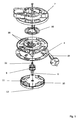
- the cable drum according to the Fig. 1 and 2 comprises an outer support member 2, a take-up drum 4, a arranged on a shaft 6 control cylinder 8 and a support member 2 oppositely disposed cover 10.
- Mit the cover 10 is a particular cross-shaped lid 11 is connected, preferably by latching.
- the cover 10 has a bent edge and forms, together with the lid 11, a spring housing in which a spring element 24 is accommodated.
- the cable drum forms a total of a mounting unit, which is intended for installation in an electrical device, in particular household appliance, such as vacuum cleaner.
- the support element 2 is fixed in place in the device.
- the take-up drum 4 is rotatably mounted relative to the support element 2 about a rotation axis 12.
- the support member 2 is formed overall disk-like and has a peripheral peripheral edge, with which it surrounds a side wall of the take-up drum 4 in the assembled state, as in particular from Fig. 2 is apparent.
- a sliding contact arrangement with slip rings 16 and sliding contacts 18 is provided for electrical connection between a cable 14 and the electrical device.
- the sliding contact arrangement is formed between the support element 2 and the take-up drum 4.
- the slip ring 16 has two electrically separate ring parts, which each have a contact tongue is assigned, which extend through the wall of the support member 2 through, so that they can be contacted from the outside.
- the sliding contacts 18 are formed in the manner of spring contacts and also extend through the side wall of the take-up drum 4 and are electrically connected on the other side with the cable 14. The electrical connection to the device via a power connection 19.
- the control cylinder 8 is located in a receptacle 20 (see. Fig. 2 ) of the take-up drum 4 and is slidably mounted on the shaft 6.
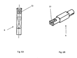
- the shaft 6 is at the same time the central axis of the cable drum and therefore extends concentrically to the axis of rotation 12.
- the shaft 6 serves to connect the individual components of the cable drum with each other.
- the shaft 6 is inserted through the individual parts and secured, for example, the end in a suitable manner.
- the shaft is slit end formed and thereby has two opposite elastic tongues 22, the locking knobs for engaging behind an edge of the support element. 2 exhibit.
- the shaft 6 is formed flattened in the region of the tongues 22, and engages in a complementarily formed bushing in the support element 2, so that the shaft 6 is rotatably connected to the support element 2 by positive engagement.
- the shaft 6 In its middle part of the shaft 6 in the manner of a polygon, in the embodiment in the manner of a square, formed and is guided by a corresponding polygonal passage in the control cylinder 8. Overall, therefore, the shaft 6 is connected on the one hand with the support member 2 and on the other hand with the control cylinder 8 positively and rotationally fixed.
- the rotationally fixed connection can in principle also be achieved elsewhere, for example by gluing or by another type of fastening.
- the details of the shaft 6 go in particular from the Fig. 6A, 6B out.
- the take-up drum 4 and the cover 10 are rotatably mounted on the shaft 6 and, for this purpose, preferably have bushings designed in the manner of sleeves.
- the shaft 6 is provided with a circular cross-section. Therefore, both a storage and an attachment of the individual components to each other takes place via the shaft 6, wherein the attachment takes place solely by positive locking.
- no positive connection is formed between the shaft 6 and the peripheral cover 10.
- the axial attachment of the cover 10 via a rotationally secure attachment in particular by means of locking lugs on the take-up drum 4.
- the take-up drum 4 in turn is secured against axial slipping by the polygonal configuration of the shaft 6 in the central region.
- a receiving space is formed, in which the particular designed as a spiral spring spring element 24 is arranged.
- the spring element 24 is intended to exert a restoring force for an automatic winding on the take-up drum 4.
- the spring element 24 is supported on the one hand at least indirectly on the support element 2 and on the other hand at least indirectly on the take-up drum 4.
- the spring element 24 is tensioned, so that when you release the cable 14 this is wound up automatically.
- the spring element 24 is inserted with a spring end 26A into a slot in the shaft 6 designed as a hollow body.
- the other spring end 26B is supported on a corresponding counter-holding element of the cover 10.
- a locking pin 28 is additionally provided in the exemplary embodiment, which is driven from the outside into the hollow shaft 6 from the outside.
- the locking pin 28 is for example a screw.
- the receptacle 20 in the direction of the axis of rotation 12 is significantly larger than the control cylinder 8, so that it can perform along the shaft 6 within the receptacle 20 a compensating movement.
- the space for the compensating movement must in this case be at least as great as the maximum distance from individual groove sections of a groove structure 30 formed on the outer jacket of the control cylinder 8.
- Fig. 2 and in particular the enlarged view according to Fig. 3 engages in this groove structure 30 a formed in the manner of a simple pin locking element 32 a.
- This is guided in the radial direction by a wall region of, for example, the sleeve-shaped and cup-shaped receptacle 20 in the exemplary embodiment.
- the blocking element 32 is guided by a sleeve-shaped sliding insert 34, which consists for example of copper. This is a form-fitting in the wall of the receptacle 20 a.
- the blocking element 32 is passed through the sliding insert 34 as far as possible without play.
- the sliding insert 34 also serves in particular for the secure guidance and for receiving the transverse forces exerted on the blocking element 32 as a result of the engagement in the groove structure 30.
- the blocking element 32 is spring-loaded at its rear end, ie it is pressed into the groove structure 30 by means of spring force.
- a leaf spring 36 is provided for this purpose.
- the head end of the locking element 32 is rounded, in particular spherical.
- a lubricant may be provided for sliding with as little friction as possible.
- the two end faces of the control cylinder 8 are formed differently. While in the Fig. 4A From the top to be recognized end face is flat, has in the Fig. 4B from the bottom to be recognized end face a cup-shaped recess 38. This recess 38 is pushed onto a ring in the receptacle 20 and thus indicates a defined mounting direction for the control cylinder 8 relative to the receptacle 20 at.
- the groove structure 30 comprises two annular edge grooves, namely a winding groove 40 and an unwinding groove 42. These two grooves 40, 42 are connected to one another via a V-shaped locking groove 44 and an alternating groove 46 extending at an angle to the axis of rotation 12.
- the groove depth that is, the distance between a groove bottom and the peripheral edge of the control cylinder 8, is variable in the individual grooves 40 to 46, so that individual groove portions increase or decrease in the radial direction, i. their radial distance from the axis of rotation 12 changes.
- the groove bottom is located at different radial heights, resulting paragraphs that act as leading edge 40A-E.
- a locking position 50 is formed at the bottom of the V-shaped locking groove 44.
- Fig. 5A, 5B the relative movement of the locking element 32 in the groove structure 30 is indicated by a rotational movement by arrows.
- the movement of the blocking element 32 during a rotation in the unwinding direction 52 is indicated by solid arrows and the movement of the blocking element 32 during a rotation in the winding-up direction 54 by dashed arrows.
- Due to the rear view according to Fig. 5B are the directions mirroring those of Fig. 5A (The control cylinder 8 is for the representation according to Fig. 5B rotated by 180 ° about a vertical axis imagined in the plane of the paper).
- the first and third leading edge 48 A, 48 C are oblique to the direction of movement the blocking element 32 oriented, therefore, form a kind of switch.
- two further leading edges 48D and 48E are formed in the groove structure 30, which extend parallel to the winding-up groove 40 and the unwinding groove 42, respectively. These additional leading edges 48D, E ensure that the blocking element 32 - regardless of the direction of rotation - from the Aufwickelnut 40 not in the locking groove 44 (leading edge 48D) or from the unwinding 42 can not get into the exchange groove 46 (leading edge 48E).
Applications Claiming Priority (2)
| Application Number | Priority Date | Filing Date | Title |
|---|---|---|---|
| CNU2007201315856U CN201128646Y (zh) | 2007-12-17 | 2007-12-17 | 中心制动定位的卷线器 |
| DE102008051156 | 2008-10-10 |
Publications (2)
| Publication Number | Publication Date |
|---|---|
| EP2072441A2 true EP2072441A2 (fr) | 2009-06-24 |
| EP2072441A3 EP2072441A3 (fr) | 2009-11-04 |
Family
ID=40377661
Family Applications (1)
| Application Number | Title | Priority Date | Filing Date |
|---|---|---|---|
| EP08021802A Withdrawn EP2072441A3 (fr) | 2007-12-17 | 2008-12-16 | Tambour à câble |
Country Status (1)
| Country | Link |
|---|---|
| EP (1) | EP2072441A3 (fr) |
Cited By (3)
| Publication number | Priority date | Publication date | Assignee | Title |
|---|---|---|---|---|
| CN102730496A (zh) * | 2011-03-29 | 2012-10-17 | 河淳株式会社 | 晾衣绳收纳体 |
| LU102966B1 (de) | 2022-06-08 | 2023-12-08 | Alexander Weimer | Vorrichtung zum Aufwickeln von Kabeln |
| DE102022114399A1 (de) | 2022-06-08 | 2023-12-14 | Alexander Weimer | Vorrichtung zum Aufwickeln von Kabeln |
Citations (1)
| Publication number | Priority date | Publication date | Assignee | Title |
|---|---|---|---|---|
| EP1251097B1 (fr) | 2001-04-19 | 2004-08-25 | Holzschuh GmbH & Co. KG | Tambour pour cable à incorporer dans les appareils électriques |
Family Cites Families (7)
| Publication number | Priority date | Publication date | Assignee | Title |
|---|---|---|---|---|
| US3490715A (en) * | 1968-07-10 | 1970-01-20 | Appleton Electric Co | Rewind control mechanism with slotted cam and toggle-activated pawl |
| DE2610916C3 (de) * | 1976-03-16 | 1980-05-08 | Kabel- Und Metallwerke Gutehoffnungshuette Ag, 3000 Hannover | Kabeltrommel mit entriegelbarer Sperre zum selbsttätigen Aufwickeln einer elektrischen Leitung |
| JPS5540181A (en) * | 1978-09-15 | 1980-03-21 | Matsushita Electric Works Ltd | Cord winding device |
| JPS597332Y2 (ja) * | 1978-12-06 | 1984-03-06 | 松下電工株式会社 | コ−ド巻取装置 |
| JPS5837900Y2 (ja) * | 1979-04-15 | 1983-08-26 | 松下電工株式会社 | コ−ド巻取装置 |
| JPS613901Y2 (fr) * | 1979-12-29 | 1986-02-06 | ||
| US6644582B1 (en) * | 2002-07-05 | 2003-11-11 | Sheng Hsin Liao | Cable reel with a positioning mechanism |
-
2008
- 2008-12-16 EP EP08021802A patent/EP2072441A3/fr not_active Withdrawn
Patent Citations (1)
| Publication number | Priority date | Publication date | Assignee | Title |
|---|---|---|---|---|
| EP1251097B1 (fr) | 2001-04-19 | 2004-08-25 | Holzschuh GmbH & Co. KG | Tambour pour cable à incorporer dans les appareils électriques |
Cited By (4)
| Publication number | Priority date | Publication date | Assignee | Title |
|---|---|---|---|---|
| CN102730496A (zh) * | 2011-03-29 | 2012-10-17 | 河淳株式会社 | 晾衣绳收纳体 |
| CN102730496B (zh) * | 2011-03-29 | 2016-02-24 | 河淳株式会社 | 晾衣绳收纳体 |
| LU102966B1 (de) | 2022-06-08 | 2023-12-08 | Alexander Weimer | Vorrichtung zum Aufwickeln von Kabeln |
| DE102022114399A1 (de) | 2022-06-08 | 2023-12-14 | Alexander Weimer | Vorrichtung zum Aufwickeln von Kabeln |
Also Published As
| Publication number | Publication date |
|---|---|
| EP2072441A3 (fr) | 2009-11-04 |
Similar Documents
| Publication | Publication Date | Title |
|---|---|---|
| DE3434905C2 (fr) | ||
| EP2272153B1 (fr) | Machine-outil électrique | |
| DE3616122C2 (de) | Lenk- und Zündschloß | |
| EP0590400A1 (fr) | Dispostif rotatif de serrage pour une chaussure de sport | |
| DE202008013230U1 (de) | Öffnungsvorrichtung für eine Ausziehführung | |
| EP1110828A2 (fr) | Dispositif de verrouillage | |
| CH692270A5 (de) | Betätigungseinrichtung für einen Vorhang. | |
| DE19852975C2 (de) | Spannungsreduzierer zum Entlasten der Zugkraft einer Aufrollvorrichtung für einen Sicherheitsgurt | |
| DE69816018T2 (de) | Cassette mit mindestens einer axial bewegbaren spule und einer vorrichtung zur blockierung der axialen bewegung dieser spule | |
| EP2072441A2 (fr) | Tambour à câble | |
| DE102004009331B4 (de) | Betätigungsmechanismus für Bowdenzüge | |
| DE69834859T2 (de) | Elektrischer Einheit mit Betätigungseinrichtung für einen Schutzschalter | |
| DE102005014701A1 (de) | Verriegelungsanlage für ein bewegliches Schliesselement | |
| DE602004006486T2 (de) | Verriegelungsmechanismus und ein damit ausgerüstetes Schiebedach | |
| WO1997010971A1 (fr) | Systeme de transport pour un conducteur electrique enroule avec inversion du sens de bobinage par formation d'une boucle | |
| DE3242152A1 (de) | Kofferschloss, insbesondere aktenkofferschloss | |
| EP0149072A2 (fr) | Tambour de câble portatif | |
| EP0193866B1 (fr) | Poignée de porte | |
| EP0180883B1 (fr) | Dispositif de bobinage d'un câble | |
| EP3540156A1 (fr) | Palier de poignée | |
| DE2841260C2 (de) | Elektromagnetisch betätigbare Kupplungseinrichtung für Türverschlüsse | |
| EP0663498A1 (fr) | Serrure cylindrique | |
| DE102011000576A1 (de) | Schloss für eine Tür oder Dergleichen sowie Handwerkzeug für ein Schloss | |
| DE2726292C2 (de) | Kabeltrommel zum selbsttätigen Aufwickeln einer elektrischen Leitung | |
| DE202007009050U1 (de) | Sicherheitsschalter mit drehbarem Antriebskopf |
Legal Events
| Date | Code | Title | Description |
|---|---|---|---|
| PUAI | Public reference made under article 153(3) epc to a published international application that has entered the european phase |
Free format text: ORIGINAL CODE: 0009012 |
|
| AK | Designated contracting states |
Kind code of ref document: A2 Designated state(s): AT BE BG CH CY CZ DE DK EE ES FI FR GB GR HR HU IE IS IT LI LT LU LV MC MT NL NO PL PT RO SE SI SK TR |
|
| AX | Request for extension of the european patent |
Extension state: AL BA MK RS |
|
| PUAL | Search report despatched |
Free format text: ORIGINAL CODE: 0009013 |
|
| AK | Designated contracting states |
Kind code of ref document: A3 Designated state(s): AT BE BG CH CY CZ DE DK EE ES FI FR GB GR HR HU IE IS IT LI LT LU LV MC MT NL NO PL PT RO SE SI SK TR |
|
| AX | Request for extension of the european patent |
Extension state: AL BA MK RS |
|
| AKX | Designation fees paid | ||
| STAA | Information on the status of an ep patent application or granted ep patent |
Free format text: STATUS: THE APPLICATION IS DEEMED TO BE WITHDRAWN |
|
| 18D | Application deemed to be withdrawn |
Effective date: 20100505 |
|
| REG | Reference to a national code |
Ref country code: DE Ref legal event code: 8566 |