EP0590400A1 - Dispostif rotatif de serrage pour une chaussure de sport - Google Patents
Dispostif rotatif de serrage pour une chaussure de sport Download PDFInfo
- Publication number
- EP0590400A1 EP0590400A1 EP93114690A EP93114690A EP0590400A1 EP 0590400 A1 EP0590400 A1 EP 0590400A1 EP 93114690 A EP93114690 A EP 93114690A EP 93114690 A EP93114690 A EP 93114690A EP 0590400 A1 EP0590400 A1 EP 0590400A1
- Authority
- EP
- European Patent Office
- Prior art keywords
- stop
- stop arm
- housing
- lock according
- sheave
- Prior art date
- Legal status (The legal status is an assumption and is not a legal conclusion. Google has not performed a legal analysis and makes no representation as to the accuracy of the status listed.)
- Granted
Links
Images

Classifications
-
- A—HUMAN NECESSITIES
- A43—FOOTWEAR
- A43C—FASTENINGS OR ATTACHMENTS OF FOOTWEAR; LACES IN GENERAL
- A43C11/00—Other fastenings specially adapted for shoes
- A43C11/16—Fastenings secured by wire, bolts, or the like
- A43C11/165—Fastenings secured by wire, bolts, or the like characterised by a spool, reel or pulley for winding up cables, laces or straps by rotation
-
- A—HUMAN NECESSITIES
- A43—FOOTWEAR
- A43C—FASTENINGS OR ATTACHMENTS OF FOOTWEAR; LACES IN GENERAL
- A43C11/00—Other fastenings specially adapted for shoes
- A43C11/16—Fastenings secured by wire, bolts, or the like
-
- Y—GENERAL TAGGING OF NEW TECHNOLOGICAL DEVELOPMENTS; GENERAL TAGGING OF CROSS-SECTIONAL TECHNOLOGIES SPANNING OVER SEVERAL SECTIONS OF THE IPC; TECHNICAL SUBJECTS COVERED BY FORMER USPC CROSS-REFERENCE ART COLLECTIONS [XRACs] AND DIGESTS
- Y10—TECHNICAL SUBJECTS COVERED BY FORMER USPC
- Y10T—TECHNICAL SUBJECTS COVERED BY FORMER US CLASSIFICATION
- Y10T24/00—Buckles, buttons, clasps, etc.
- Y10T24/21—Strap tighteners
- Y10T24/2183—Ski, boot, and shoe fasteners
Definitions
- the invention relates to a twist lock for a sports shoe, according to the preamble of claim 1.
- a twist lock of the type required in the preamble of claim 1 is known from EP-A-393 380.
- the flaps of a sports shoe can be contracted and released by changing the effective length of a traction cable arrangement by a rotary movement of a rotary actuating device in one direction or the other.
- a locking blade device is arranged between the rotary actuation device and the sheave, which contains an intermediate element which can be rotated while maintaining an empty travel, a pawl carried by this intermediate element and a toothed ring incorporated in a housing cover, whereby the sheave is rotated by the rotary actuating device, preferably with the interposition of a planetary gear mechanism, the sun gear of which has a downwardly extending, pivot-like axial extension which forms a central bearing journal for the sheave.
- the rotary actuating device can preferably be designed as a cap-shaped rotary handle and can be screwed to a journal end of the sun gear which extends axially upward through a housing cover, the lateral peripheral wall of the rotary handle largely covering the housing and its cover at the bottom.
- the invention is therefore based on the object of developing a rotary closure in the preamble of claim 1 while maintaining the advantages of the known embodiment described above in such a way that with a relatively simple structural design, a rotary movement of the pulley beyond two turns is made possible.
- the stop device is essentially formed by two flat stop arms which are mounted coaxially with respect to one another about the central housing axis and are arranged above one another.
- the upper first stop arm is located directly below the sheave, the driving projection of which is designed and arranged such that after the first rotation of the sheave and when this rotational movement continues, it only comes into engagement with the first stop arm and the sheave together with this first stop arm then one can make a second turn.
- the lower second stop arm is in driving connection with the first stop arm via a driving cam in such a way that this second stop arm only becomes effective after a second rotation of the rope sheave and upon a further continuation of this rotary movement.
- the stationary housing stop is arranged in the path of movement of the second stop arm at a point which is shortly before the completion of a complete revolution of this second stop arm.
- the rope sheave can carry out a maximum of approximately three revolutions, for example approximately 2 3/4 revolutions, before a further rotary movement is prevented or limited by the stationary housing stop (the latter occurs to damage a pull rope by to rule out overstretching).
- the twist lock according to the invention can be attached or fastened on the shaft of any suitable sports shoe, so that its traction cable arrangement can be connected in a favorable manner to locking flaps or other parts of the sports shoe which can be contracted, in order thereby to be able to adapt the shoe precisely to the foot of a user.
- this rotary closure according to the invention can be designed in the same way as in EP-A-393 380 described at the outset, so that in the drawing only the lower one, which is relevant for explaining the present invention Part of this twist lock is illustrated, while the upper part with pawl device, rotary actuating device, cover, etc. is of the same construction as the aforementioned known embodiment, to which express reference is made.
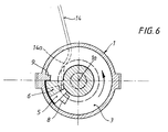
- the lower part of the twist lock has an approximately shell-shaped, essentially circular housing 1, which can be fastened in a suitable manner to a sports shoe, not shown, on its shaft, for example with the aid of lateral fastening tabs 2.
- this housing 1 there is one central housing axis 1 a rotatably operable rope pulley 3 rotatably mounted, on which a pull rope arrangement 4 - depending on the rotary movement - can be wound or unwound, in order thereby to be able to change the effective length of the rope pull arrangement 4 in the desired manner.
- two traction cable ends 4a, 4b are fastened diametrically opposite to the pulley 3, which ends may belong to a single traction cable or to two traction cables.
- the rope sheave 3 is accommodated in the housing 1 in such a way that the outer peripheral edge of its upper sheave part 3a is guided in a kind of annular groove 1b on the upper edge of the housing.
- the pulley 3 has a central bore 3b into which a downwardly extending, trunnion-like axial extension of a sun gear (not shown in more detail) of a planetary gear belonging to the rotary actuation device extends, this trunnion-like extension forming a central bearing journal for the pulley 3.
- a stop device is rotatably mounted in the housing 1, which is essentially coaxial with one another by two central housing axis 1a rotatably mounted, superimposed flat stop arms, namely an upper first stop arm 5 and a lower second stop arm 6 is formed.
- the upper first stop arm 5 has a central bearing section 5a and a circular sector-shaped outer stop section 5b adjoining it radially outward, and in approximately the same way the lower second stop arm 6 also has a central bearing section 6a and a circular sector-shaped adjoining it radially outward outer stop section 6b.
- an upwardly projecting driving cam 7 is firmly attached, the height of which is at most as large as the material thickness of the upper stop arm 5, which can be seen in FIG. 1 (left half).
- a driving projection 8 is fixedly attached, which is located radially within the driving cam 7 and is at most as high as the material thickness of the first stop arm 5.
- a stationary stop 9 is also provided on the housing base 1c and in the peripheral edge region, which serves to limit the rotational movement of the lower second stop arm 6 and thus - as will be explained in more detail - also the pulley 3 in both directions of rotation.
- this housing stop 9 extends from the housing base 1c upwards by an amount that is at most as large as the material thickness of the lower second stop arm 6.
- the central bearing section 6a of the second stop arm 6 has an axially downwardly extending, circular bearing projection 10, which is mounted and guided in a sliding manner in a central bearing bore 11 in the housing base 1c. At least the remaining part of the central bearing section 6a of this second stop arm 6, but preferably also at least the largest part of the outer stop section 6b, is slidably supported on the housing base 1c.
- the Central bearing section 6a of the second stop arm 6 also has a bearing pin 12 which extends coaxially to the bearing extension 10 and which fits into a central bearing bore 5a 'in the bearing section 5a of the upper first stop arm 5, so that for this bearing section 5a and thus also for the whole upper first stop arm 5 in a very simple manner, a reliable pivot bearing and guidance is created.
- the twist lock can be made at least partially from a suitable, preferably castable and machinable plastic material. It is furthermore particularly advantageous with regard to the relatively simple and inexpensive production if at least the housing 1, the rope pulley 3 and the stop arms 5, 6 are made of such plastic material.
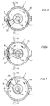
- FIGS. 2 to 5 A winding process of the pull cable arrangement 4 or the pull cable ends 4a and 4b on the sheave 3 is explained below with reference to FIGS. 2 to 5, it being emphasized again that these FIGS. 2 to 5 horizontal sectional views corresponding to the section line II-II in FIG. 1 show from below.
- FIG. 2 The zero position is illustrated in FIG. 2, in which the pull rope arrangement 4 is completely unwound from the sheave.
- the outer stop section 6b rests on one side of the stationary housing stop 9, while on one side of the driving cam 7 the outer stop section 5b of the upper first stop arm 5 rests on one side again the driving projection 8 of the sheave is present.
- the traction cable arrangement 4 or its traction cable ends 4a and 4b are now to be wound onto the pulley 3, then the pulley 3 is rotated in the direction of arrow 13 by means of the rotary actuating device explained at the beginning.
Applications Claiming Priority (2)
| Application Number | Priority Date | Filing Date | Title |
|---|---|---|---|
| DE9213187U | 1992-09-30 | ||
| DE9213187U DE9213187U1 (fr) | 1992-09-30 | 1992-09-30 |
Publications (2)
| Publication Number | Publication Date |
|---|---|
| EP0590400A1 true EP0590400A1 (fr) | 1994-04-06 |
| EP0590400B1 EP0590400B1 (fr) | 1996-03-27 |
Family
ID=6884329
Family Applications (1)
| Application Number | Title | Priority Date | Filing Date |
|---|---|---|---|
| EP93114690A Expired - Lifetime EP0590400B1 (fr) | 1992-09-30 | 1993-09-13 | Dispostif rotatif de serrage pour une chaussure de sport |
Country Status (5)
| Country | Link |
|---|---|
| US (1) | US5425161A (fr) |
| EP (1) | EP0590400B1 (fr) |
| JP (1) | JPH06178704A (fr) |
| AT (1) | ATE135893T1 (fr) |
| DE (2) | DE9213187U1 (fr) |
Families Citing this family (59)
| Publication number | Priority date | Publication date | Assignee | Title |
|---|---|---|---|---|
| DE4302401A1 (de) * | 1993-01-28 | 1994-08-04 | Egolf Heinz | Drehverschluß |
| US20060156517A1 (en) | 1997-08-22 | 2006-07-20 | Hammerslag Gary R | Reel based closure system |
| US6416074B1 (en) | 1999-06-15 | 2002-07-09 | The Burton Corporation | Strap for a snowboard boot, binding or interface |
| US6267390B1 (en) | 1999-06-15 | 2001-07-31 | The Burton Corporation | Strap for a snowboard boot, binding or interface |
| JP2004135875A (ja) * | 2002-10-17 | 2004-05-13 | Konsho Ryu | 巻取り装置付き靴 |
| US7281341B2 (en) | 2003-12-10 | 2007-10-16 | The Burton Corporation | Lace system for footwear |
| EP1814417B1 (fr) | 2004-10-29 | 2014-04-16 | Boa Technology, Inc. | Système de fermeture à enrouleur |
| KR101553243B1 (ko) | 2006-09-12 | 2015-09-15 | 보아 테크놀러지, 인크. | 지지대, 보호복 및 유사한 물품을 위한 잠금 시스템 |
| US20090044441A1 (en) * | 2007-08-13 | 2009-02-19 | Ryan Neal | Snap terminal tackle |
| EP2237692B1 (fr) | 2008-01-18 | 2015-01-07 | Boa Technology, Inc. | Système de fermeture |
| EP2805639B2 (fr) | 2008-11-21 | 2021-08-18 | Boa Technology, Inc. | Système de laçage à enrouleur |
| US8245371B2 (en) * | 2009-04-01 | 2012-08-21 | Chin Chu Chen | String securing device |
| US8474157B2 (en) | 2009-08-07 | 2013-07-02 | Pierre-Andre Senizergues | Footwear lacing system |
| EP2525679B1 (fr) | 2010-01-21 | 2020-04-01 | Boa Technology, Inc. | Guides pour systèmes de laçage |
| US10070695B2 (en) | 2010-04-30 | 2018-09-11 | Boa Technology Inc. | Tightening mechanisms and applications including the same |
| US9375053B2 (en) | 2012-03-15 | 2016-06-28 | Boa Technology, Inc. | Tightening mechanisms and applications including the same |
| DE112011101525B4 (de) | 2010-04-30 | 2020-07-09 | Boa Technology, Inc. | Aufrollerbasiertes Schnürsystem |
| US9149089B2 (en) | 2010-07-01 | 2015-10-06 | Boa Technology, Inc. | Lace guide |
| EP2588044B1 (fr) | 2010-07-01 | 2016-11-09 | 3M Innovative Properties Company | Attaches utilisant des systèmes de laçage |
| KR101099458B1 (ko) * | 2011-07-25 | 2011-12-27 | 주식회사 신경 | 신발끈 조임장치 |
| US9101181B2 (en) | 2011-10-13 | 2015-08-11 | Boa Technology Inc. | Reel-based lacing system |
| US9179729B2 (en) | 2012-03-13 | 2015-11-10 | Boa Technology, Inc. | Tightening systems |
| EP3491954B1 (fr) | 2012-08-31 | 2021-01-06 | NIKE Innovate C.V. | Système de tension motorisé |
| DE112013005273B4 (de) | 2012-11-02 | 2017-08-24 | Boa Technology, Inc. | Kupplungsteile für Verschlussvorrichtungen und -systeme |
| US9737115B2 (en) | 2012-11-06 | 2017-08-22 | Boa Technology Inc. | Devices and methods for adjusting the fit of footwear |
| US9439477B2 (en) | 2013-01-28 | 2016-09-13 | Boa Technology Inc. | Lace fixation assembly and system |
| US10702409B2 (en) | 2013-02-05 | 2020-07-07 | Boa Technology Inc. | Closure devices for medical devices and methods |
| US10251451B2 (en) | 2013-03-05 | 2019-04-09 | Boa Technology Inc. | Closure devices including incremental release mechanisms and methods therefor |
| EP2964048B1 (fr) | 2013-03-05 | 2019-08-28 | Boa Technology Inc. | Systèmes et dispositifs de fermeture automatique de dispositifs médicaux |
| US9357807B2 (en) | 2013-03-15 | 2016-06-07 | Under Armour, Inc. | Size adjustment arrangement for a garment |
| KR20230155599A (ko) | 2013-04-01 | 2023-11-10 | 보아 테크놀러지, 인크. | 릴 기반의 폐쇄 시스템을 포함하도록 신발류를 개장하기 위한 방법 및 장치 |
| DK3003087T3 (da) | 2013-06-05 | 2020-08-03 | Boa Tech Inc | Integrerede lukningsanordningskomponenter og fremgangsmåder |
| US10076160B2 (en) | 2013-06-05 | 2018-09-18 | Boa Technology Inc. | Integrated closure device components and methods |
| US9629417B2 (en) | 2013-07-02 | 2017-04-25 | Boa Technology Inc. | Tension limiting mechanisms for closure devices and methods therefor |
| WO2015006616A1 (fr) | 2013-07-10 | 2015-01-15 | Boa Technology Inc. | Dispositifs de fermeture comprenant des mécanismes de relâchement incrémentiels et procédés associés |
| US9700101B2 (en) | 2013-09-05 | 2017-07-11 | Boa Technology Inc. | Guides and components for closure systems and methods therefor |
| US9681705B2 (en) | 2013-09-13 | 2017-06-20 | Boa Technology Inc. | Failure compensating lace tension devices and methods |
| EP3071159A1 (fr) | 2013-11-18 | 2016-09-28 | Boa Technology, Inc. | Procédés et dispositifs permettant une fermeture automatique de prothèses et d'orthèses |
| USD835976S1 (en) | 2014-01-16 | 2018-12-18 | Boa Technology Inc. | Coupling member |
| USD751281S1 (en) | 2014-08-12 | 2016-03-15 | Boa Technology, Inc. | Footwear tightening reels |
| USD767269S1 (en) | 2014-08-26 | 2016-09-27 | Boa Technology Inc. | Footwear tightening reel |
| US20160058127A1 (en) | 2014-08-28 | 2016-03-03 | Boa Technology Inc. | Devices and methods for enhancing the fit of boots and other footwear |
| USD758061S1 (en) | 2014-09-08 | 2016-06-07 | Boa Technology, Inc. | Lace tightening device |
| WO2016054317A1 (fr) | 2014-10-01 | 2016-04-07 | Ossur Hf | Support pour articles et procédés pour les utiliser |
| US10575591B2 (en) | 2014-10-07 | 2020-03-03 | Boa Technology Inc. | Devices, methods, and systems for remote control of a motorized closure system |
| EP3218073B1 (fr) | 2014-11-14 | 2021-05-19 | The Burton Corporation | Fixation de planche à neige |
| US9149711B1 (en) | 2014-11-14 | 2015-10-06 | The Burton Corporation | Snowboard binding and boot |
| US9220970B1 (en) | 2014-11-14 | 2015-12-29 | The Burton Corporation | Snowboard binding and boot |
| USD776421S1 (en) | 2015-01-16 | 2017-01-17 | Boa Technology, Inc. | In-footwear lace tightening reel |
| USD835898S1 (en) | 2015-01-16 | 2018-12-18 | Boa Technology Inc. | Footwear lace tightening reel stabilizer |
| US10004297B2 (en) | 2015-10-15 | 2018-06-26 | Boa Technology Inc. | Lacing configurations for footwear |
| WO2018026957A1 (fr) | 2016-08-02 | 2018-02-08 | Boa Technology Inc. | Guides d'élément de tension d'un système de laçage |
| KR102494446B1 (ko) | 2016-12-09 | 2023-02-01 | 보아 테크놀러지, 인크. | 릴 기반의 폐쇄 시스템 |
| US10543630B2 (en) | 2017-02-27 | 2020-01-28 | Boa Technology Inc. | Reel based closure system employing a friction based tension mechanism |
| US11357279B2 (en) | 2017-05-09 | 2022-06-14 | Boa Technology Inc. | Closure components for a helmet layer and methods for installing same |
| US10772384B2 (en) | 2017-07-18 | 2020-09-15 | Boa Technology Inc. | System and methods for minimizing dynamic lace movement |
| KR20220003067A (ko) | 2019-05-01 | 2022-01-07 | 보아 테크놀러지, 인크. | 릴 기반 폐쇄 시스템 |
| USD948200S1 (en) * | 2021-06-07 | 2022-04-12 | Aijun Zhang | Shoe buckle |
| CN114162419B (zh) * | 2021-11-19 | 2023-01-06 | 深圳市日新达工业自动化有限公司 | 一种鞋扣组装贴标流水线 |
Citations (3)
| Publication number | Priority date | Publication date | Assignee | Title |
|---|---|---|---|---|
| EP0255869A2 (fr) * | 1986-08-08 | 1988-02-17 | Egolf, Heinz | Fermeture rotative pour chaussure de sport, en particulier chaussure de ski |
| EP0290847A2 (fr) * | 1987-05-15 | 1988-11-17 | NORDICA S.p.A. | Dispositif de fermeture et d'ajustement, en particulier pour chaussures de ski |
| EP0393380A1 (fr) * | 1989-04-20 | 1990-10-24 | Egolf, Heinz | Fermeture tournante pour chaussure de sport |
Family Cites Families (4)
| Publication number | Priority date | Publication date | Assignee | Title |
|---|---|---|---|---|
| IT1193578B (it) * | 1981-01-28 | 1988-07-08 | Nordica Spa | Dispositivo di chiusura particolarmente per scarponi da sci |
| FR2569087B1 (fr) * | 1984-08-17 | 1987-01-09 | Salomon Sa | Chaussure de ski |
| US4787124A (en) * | 1986-09-23 | 1988-11-29 | Nordica S.P.A. | Multiple-function actuation device particularly usable in ski boots |
| IT1220010B (it) * | 1987-07-03 | 1990-06-06 | Nordica Spa | Dispositivo di serraggio e regolazione particolarmente per scarponi da sci |
-
1992
- 1992-09-30 DE DE9213187U patent/DE9213187U1/de not_active Expired - Lifetime
-
1993
- 1993-09-13 EP EP93114690A patent/EP0590400B1/fr not_active Expired - Lifetime
- 1993-09-13 DE DE59302037T patent/DE59302037D1/de not_active Expired - Fee Related
- 1993-09-13 AT AT93114690T patent/ATE135893T1/de active
- 1993-09-13 US US08/121,272 patent/US5425161A/en not_active Expired - Fee Related
- 1993-09-14 JP JP5229073A patent/JPH06178704A/ja active Pending
Patent Citations (3)
| Publication number | Priority date | Publication date | Assignee | Title |
|---|---|---|---|---|
| EP0255869A2 (fr) * | 1986-08-08 | 1988-02-17 | Egolf, Heinz | Fermeture rotative pour chaussure de sport, en particulier chaussure de ski |
| EP0290847A2 (fr) * | 1987-05-15 | 1988-11-17 | NORDICA S.p.A. | Dispositif de fermeture et d'ajustement, en particulier pour chaussures de ski |
| EP0393380A1 (fr) * | 1989-04-20 | 1990-10-24 | Egolf, Heinz | Fermeture tournante pour chaussure de sport |
Also Published As
| Publication number | Publication date |
|---|---|
| DE59302037D1 (de) | 1996-05-02 |
| ATE135893T1 (de) | 1996-04-15 |
| JPH06178704A (ja) | 1994-06-28 |
| US5425161A (en) | 1995-06-20 |
| DE9213187U1 (fr) | 1992-11-26 |
| EP0590400B1 (fr) | 1996-03-27 |
Similar Documents
| Publication | Publication Date | Title |
|---|---|---|
| EP0590400B1 (fr) | Dispostif rotatif de serrage pour une chaussure de sport | |
| EP0393380B1 (fr) | Fermeture tournante pour chaussure de sport | |
| EP0255869B1 (fr) | Fermeture rotative pour chaussure de sport, en particulier chaussure de ski | |
| EP0615705B1 (fr) | Système rotatif de fermeture | |
| DE4012775C2 (de) | Haspelbremskraft-Schaltvorrichtung für eine Angelschnurhaspel | |
| DE2517359C2 (de) | Kurbelbetätigtes Bandmaß | |
| DE3922339C1 (fr) | ||
| EP0412290A2 (fr) | Fermeture rotative pour chaussure de sport, en particulier pour chaussure de ski | |
| DE3905455A1 (de) | Vorrichtung zum einstellen der biegung eines endoskops | |
| EP0475017A2 (fr) | Dispositif de réglage pour commande par câble | |
| EP1332306B1 (fr) | Dispositif de reglage a rotation | |
| DE3916009C5 (de) | Schneidkopf für ein Pflanzenschneidgerät | |
| EP0150061B1 (fr) | Moulinet de pêche | |
| EP4041018A1 (fr) | Fermeture rotative dotée d'un élément de tension | |
| DE3146289C2 (fr) | ||
| DE3005968A1 (de) | Fadenschneider | |
| DE3205491A1 (de) | Raffstore | |
| DE102017200386A1 (de) | Schnurzuganordnung für bauliche Abdeckung mit einem Bremselement und zugehörigem Vorspannelement | |
| EP2072441A2 (fr) | Tambour à câble | |
| EP0556420A1 (fr) | Manuelle d'entraînement pour partie mobile d'un toit de véhicule | |
| EP0204862B1 (fr) | Toit pare-soleil pour véhicules | |
| DE3027872A1 (de) | Drehkurbeltrieb | |
| DE3825363C2 (fr) | ||
| DE69908064T2 (de) | Seilantriebsvorrichtung oder dergleichen für einen Rolladen | |
| DE1191228B (de) | Vorrichtung zum Einspulen von Filmstreifen in eine Behandlungsspule |
Legal Events
| Date | Code | Title | Description |
|---|---|---|---|
| PUAI | Public reference made under article 153(3) epc to a published international application that has entered the european phase |
Free format text: ORIGINAL CODE: 0009012 |
|
| AK | Designated contracting states |
Kind code of ref document: A1 Designated state(s): AT CH DE ES FR GB IT LI |
|
| 17P | Request for examination filed |
Effective date: 19940808 |
|
| 17Q | First examination report despatched |
Effective date: 19950914 |
|
| GRAH | Despatch of communication of intention to grant a patent |
Free format text: ORIGINAL CODE: EPIDOS IGRA |
|
| GRAA | (expected) grant |
Free format text: ORIGINAL CODE: 0009210 |
|
| AK | Designated contracting states |
Kind code of ref document: B1 Designated state(s): AT CH DE ES FR GB IT LI |
|
| PG25 | Lapsed in a contracting state [announced via postgrant information from national office to epo] |
Ref country code: GB Effective date: 19960327 Ref country code: FR Effective date: 19960327 Ref country code: ES Free format text: THE PATENT HAS BEEN ANNULLED BY A DECISION OF A NATIONAL AUTHORITY Effective date: 19960327 |
|
| REF | Corresponds to: |
Ref document number: 135893 Country of ref document: AT Date of ref document: 19960415 Kind code of ref document: T |
|
| REF | Corresponds to: |
Ref document number: 59302037 Country of ref document: DE Date of ref document: 19960502 |
|
| REG | Reference to a national code |
Ref country code: CH Ref legal event code: NV Representative=s name: BUGNION S.A. |
|
| ITF | It: translation for a ep patent filed |
Owner name: MODIANO & ASSOCIATI S.R.L. |
|
| EN | Fr: translation not filed | ||
| PGFP | Annual fee paid to national office [announced via postgrant information from national office to epo] |
Ref country code: CH Payment date: 19960827 Year of fee payment: 4 |
|
| PG25 | Lapsed in a contracting state [announced via postgrant information from national office to epo] |
Ref country code: AT Effective date: 19960913 |
|
| GBV | Gb: ep patent (uk) treated as always having been void in accordance with gb section 77(7)/1977 [no translation filed] |
Effective date: 19960327 |
|
| PGFP | Annual fee paid to national office [announced via postgrant information from national office to epo] |
Ref country code: DE Payment date: 19961122 Year of fee payment: 4 |
|
| PLBE | No opposition filed within time limit |
Free format text: ORIGINAL CODE: 0009261 |
|
| STAA | Information on the status of an ep patent application or granted ep patent |
Free format text: STATUS: NO OPPOSITION FILED WITHIN TIME LIMIT |
|
| 26N | No opposition filed | ||
| PG25 | Lapsed in a contracting state [announced via postgrant information from national office to epo] |
Ref country code: LI Free format text: LAPSE BECAUSE OF NON-PAYMENT OF DUE FEES Effective date: 19970930 Ref country code: CH Free format text: LAPSE BECAUSE OF NON-PAYMENT OF DUE FEES Effective date: 19970930 |
|
| REG | Reference to a national code |
Ref country code: CH Ref legal event code: PL |
|
| PG25 | Lapsed in a contracting state [announced via postgrant information from national office to epo] |
Ref country code: DE Free format text: LAPSE BECAUSE OF NON-PAYMENT OF DUE FEES Effective date: 19980603 |
|
| PG25 | Lapsed in a contracting state [announced via postgrant information from national office to epo] |
Ref country code: IT Free format text: LAPSE BECAUSE OF NON-PAYMENT OF DUE FEES;WARNING: LAPSES OF ITALIAN PATENTS WITH EFFECTIVE DATE BEFORE 2007 MAY HAVE OCCURRED AT ANY TIME BEFORE 2007. THE CORRECT EFFECTIVE DATE MAY BE DIFFERENT FROM THE ONE RECORDED. Effective date: 20050913 |