EP2072441A2 - Cable drum - Google Patents
Cable drum Download PDFInfo
- Publication number
- EP2072441A2 EP2072441A2 EP08021802A EP08021802A EP2072441A2 EP 2072441 A2 EP2072441 A2 EP 2072441A2 EP 08021802 A EP08021802 A EP 08021802A EP 08021802 A EP08021802 A EP 08021802A EP 2072441 A2 EP2072441 A2 EP 2072441A2
- Authority
- EP
- European Patent Office
- Prior art keywords
- groove
- winding
- cable
- unwinding
- cable drum
- Prior art date
- Legal status (The legal status is an assumption and is not a legal conclusion. Google has not performed a legal analysis and makes no representation as to the accuracy of the status listed.)
- Withdrawn
Links
Images

Classifications
-
- B—PERFORMING OPERATIONS; TRANSPORTING
- B65—CONVEYING; PACKING; STORING; HANDLING THIN OR FILAMENTARY MATERIAL
- B65H—HANDLING THIN OR FILAMENTARY MATERIAL, e.g. SHEETS, WEBS, CABLES
- B65H75/00—Storing webs, tapes, or filamentary material, e.g. on reels
- B65H75/02—Cores, formers, supports, or holders for coiled, wound, or folded material, e.g. reels, spindles, bobbins, cop tubes, cans, mandrels or chucks
- B65H75/34—Cores, formers, supports, or holders for coiled, wound, or folded material, e.g. reels, spindles, bobbins, cop tubes, cans, mandrels or chucks specially adapted or mounted for storing and repeatedly paying-out and re-storing lengths of material provided for particular purposes, e.g. anchored hoses, power cables
- B65H75/38—Cores, formers, supports, or holders for coiled, wound, or folded material, e.g. reels, spindles, bobbins, cop tubes, cans, mandrels or chucks specially adapted or mounted for storing and repeatedly paying-out and re-storing lengths of material provided for particular purposes, e.g. anchored hoses, power cables involving the use of a core or former internal to, and supporting, a stored package of material
- B65H75/44—Constructional details
- B65H75/4418—Arrangements for stopping winding or unwinding; Arrangements for releasing the stop means
- B65H75/4428—Arrangements for stopping winding or unwinding; Arrangements for releasing the stop means acting on the reel or on a reel blocking mechanism
- B65H75/4434—Arrangements for stopping winding or unwinding; Arrangements for releasing the stop means acting on the reel or on a reel blocking mechanism actuated by pulling on or imparting an inclination to the material
-
- B—PERFORMING OPERATIONS; TRANSPORTING
- B65—CONVEYING; PACKING; STORING; HANDLING THIN OR FILAMENTARY MATERIAL
- B65H—HANDLING THIN OR FILAMENTARY MATERIAL, e.g. SHEETS, WEBS, CABLES
- B65H2701/00—Handled material; Storage means
- B65H2701/30—Handled filamentary material
- B65H2701/34—Handled filamentary material electric cords or electric power cables
Definitions
- the invention relates to a cable drum, in particular for installation in a household electrical appliance, having the features of the preamble of patent claim 1.
- Such a cable drum is for example from the EP 1 251 097 B1 refer to.
- the cable drum has a take-up drum for winding an electric cable, wherein the take-up drum is arranged rotatably about a rotation axis on a support element.
- Such cable drums are usually installed as prefabricated units in electrical appliances, for example in vacuum cleaner. In such devices the highest possible ease of use is sought. Therefore, such cable drums are designed for automatically winding the cable. In order to prevent unwanted winding when the cable is pulled out, a locking or blocking of the automatic winding is regularly provided.
- the invention has for its object to provide an improved self-winding cable drum with automatic locking and releasing the lock by train on the cable.
- the cable drum has in this case a control mechanism for the controlled locking of the take-up drum against an automatic winding, wherein the control mechanism on the one hand has a centrally disposed about a rotation axis control cylinder with a cylinder jacket in which a groove structure is formed.
- the control mechanism further comprises a blocking element which engages in the groove structure. The locking element and the control cylinder make a relative movement to each other when the take-up drum rotates.
- the groove structure is formed on the control cylinder arranged centrally in the interior of the cable drum. This results in a particularly compact design and due to the central arrangement also a low mechanical load on the individual components. Investigations have shown that this overall improves the service life of the cable drum. It is essential here that the contact path, that is to say the path which covers the blocking element in the groove structure, is comparatively short due to the central arrangement.
- the control mechanism here is generally designed such that an automatic locking takes place when the cable is unwound and then released. It is therefore initially prevented in this case, an automatic winding. By a short pull on the cable, the lock can be released again, so that then the cable is wound up automatically.
- the groove structure is designed such that after unwinding of the cable, the blocking element slides in a blocking position in which the automatic winding is locked. After a short pull on the cable, the blocking element slides out of the blocking position, so that the blocking is released and the automatic winding takes place.
- control cylinder is arranged in a particular sleeve-shaped receptacle of the take-up drum and rotatably connected to the support member.
- the blocking element with the take-up drum is at least indirectly connected.
- the groove structure is in this case formed in particular in the outer jacket of the control cylinder and the blocking element engages in the radial direction in the groove structure.
- the groove structure is formed on the take-up drum, for example on the cylindrical inner wall of the sleeve-shaped receptacle, and that the blocking element is arranged on a central axis and rotatably connected to the support member.
- the control cylinder by means of a shaft or bolt with the support member is rotatably connected.
- the shaft is a separate component and is positively connected to the control cylinder.
- the control cylinder is preferably mounted displaceably in the direction of the axis of rotation in order to be able to carry out a compensation movement in the direction of the axis of rotation.
- the recording of the take-up drum is for this purpose sufficiently long dimensioned, i. in the direction of the axis of rotation, the receptacle has a length which corresponds at least to one and a half to two times the length of the control cylinder.
- the blocking element is mounted displaceably in the radial direction against a spring force. This ensures that the blocking element can execute compensation movements in the radial direction, which are required, for example, by the special groove structure. At the same time the burden of the locking element or the groove structure is kept low in terms of the longest possible life.
- the blocking element is pin-shaped and formed with a rounded pin end.
- the blocking element is slidably guided in a sliding insert for a permanently safe and low-friction as possible storage.
- the sliding insert is in this case arranged in particular in a wall of the take-up drum.
- the sliding insert is preferably formed in the manner of a sleeve, for example made of metal.
- the groove structure according to a preferred embodiment, a first and a second edge-side annular groove, which are referred to as Aufwickelnut and Abwickelnut.
- the two annular grooves are in this case connected on the one hand via a sloping exchange groove and on the other hand via a particular V-shaped locking groove.
- the Aufwickelnut slides the locking element in a winding of the cable (in the winding).
- the unwinding slides when unwinding the cable (in the unwinding).
- the groove structure is now designed such that after unwinding the locking element automatically - due to the return movement of the spring element - runs in the locking groove in a blocking position.
- the blocking element is guided from the blocking position into the winding groove during a short pull on the cable and can then slide there in the winding direction in the winding groove until the cable is completely wound up. If the cable is subsequently unwound again, then the blocking element slides over the exchange groove from the winding-up groove into the unwinding groove.
- the groove base of the individual grooves rises or falls, in such a way that in each case a guide edge for the blocking element is formed at the transition between the respective annular groove and the exchange groove or the locking groove is.
- the respective leading edge is effective only in one direction of rotation, namely either in the unwinding or in the winding. This ensures that, for example, when unwinding the blocking element remains in the unwinding, but is then passed for winding in the locking groove by means of such a leading edge.
- an effective first in the winding direction leading edge is preferably formed to the locking groove.
- take-up effective first leading edge is meant that the blocking element only runs against this leading edge when the take-up reel is rotated in the take-up direction. In contrast, the blocking element slides over this leading edge within the unwinding groove, as long as the take-up reel is rotated in the unwinding direction.
- This first leading edge serves to ensure that the blocking element automatically slides from the unwinding groove into the blocking position of the blocking groove when the direction of reversal from the unwinding direction into the winding direction is reversed.
- the blocking position is located in particular in the bottom of the V-shaped locking groove.
- a second leading edge is formed, which is effective in the unwinding and oriented to the unwinding. So is the locking element in the locked position and the take-up drum is actuated in the unwinding (namely, by a short pull on the cable), so prevents the second leading edge that the blocking element slides in the unwinding. Rather, the blocking element is passed through the V-shaped configuration of the locking groove in the Aufwickelnut.
- a sliding contact arrangement is provided, via which the electrical connection between the cable and an electrical load inside the electrical device, for example an electric motor takes place.
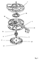
- the cable drum according to the Fig. 1 and 2 comprises an outer support member 2, a take-up drum 4, a arranged on a shaft 6 control cylinder 8 and a support member 2 oppositely disposed cover 10.
- Mit the cover 10 is a particular cross-shaped lid 11 is connected, preferably by latching.
- the cover 10 has a bent edge and forms, together with the lid 11, a spring housing in which a spring element 24 is accommodated.
- the cable drum forms a total of a mounting unit, which is intended for installation in an electrical device, in particular household appliance, such as vacuum cleaner.
- the support element 2 is fixed in place in the device.
- the take-up drum 4 is rotatably mounted relative to the support element 2 about a rotation axis 12.
- the support member 2 is formed overall disk-like and has a peripheral peripheral edge, with which it surrounds a side wall of the take-up drum 4 in the assembled state, as in particular from Fig. 2 is apparent.
- a sliding contact arrangement with slip rings 16 and sliding contacts 18 is provided for electrical connection between a cable 14 and the electrical device.
- the sliding contact arrangement is formed between the support element 2 and the take-up drum 4.
- the slip ring 16 has two electrically separate ring parts, which each have a contact tongue is assigned, which extend through the wall of the support member 2 through, so that they can be contacted from the outside.
- the sliding contacts 18 are formed in the manner of spring contacts and also extend through the side wall of the take-up drum 4 and are electrically connected on the other side with the cable 14. The electrical connection to the device via a power connection 19.
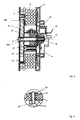
- the control cylinder 8 is located in a receptacle 20 (see. Fig. 2 ) of the take-up drum 4 and is slidably mounted on the shaft 6.
- the shaft 6 is at the same time the central axis of the cable drum and therefore extends concentrically to the axis of rotation 12.
- the shaft 6 serves to connect the individual components of the cable drum with each other.
- the shaft 6 is inserted through the individual parts and secured, for example, the end in a suitable manner.
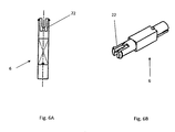
- the shaft is slit end formed and thereby has two opposite elastic tongues 22, the locking knobs for engaging behind an edge of the support element. 2 exhibit.
- the shaft 6 is formed flattened in the region of the tongues 22, and engages in a complementarily formed bushing in the support element 2, so that the shaft 6 is rotatably connected to the support element 2 by positive engagement.
- the shaft 6 In its middle part of the shaft 6 in the manner of a polygon, in the embodiment in the manner of a square, formed and is guided by a corresponding polygonal passage in the control cylinder 8. Overall, therefore, the shaft 6 is connected on the one hand with the support member 2 and on the other hand with the control cylinder 8 positively and rotationally fixed.
- the rotationally fixed connection can in principle also be achieved elsewhere, for example by gluing or by another type of fastening.
- the details of the shaft 6 go in particular from the Fig. 6A, 6B out.
- the take-up drum 4 and the cover 10 are rotatably mounted on the shaft 6 and, for this purpose, preferably have bushings designed in the manner of sleeves.
- the shaft 6 is provided with a circular cross-section. Therefore, both a storage and an attachment of the individual components to each other takes place via the shaft 6, wherein the attachment takes place solely by positive locking.
- no positive connection is formed between the shaft 6 and the peripheral cover 10.
- the axial attachment of the cover 10 via a rotationally secure attachment in particular by means of locking lugs on the take-up drum 4.
- the take-up drum 4 in turn is secured against axial slipping by the polygonal configuration of the shaft 6 in the central region.
- a receiving space is formed, in which the particular designed as a spiral spring spring element 24 is arranged.
- the spring element 24 is intended to exert a restoring force for an automatic winding on the take-up drum 4.
- the spring element 24 is supported on the one hand at least indirectly on the support element 2 and on the other hand at least indirectly on the take-up drum 4.
- the spring element 24 is tensioned, so that when you release the cable 14 this is wound up automatically.
- the spring element 24 is inserted with a spring end 26A into a slot in the shaft 6 designed as a hollow body.
- the other spring end 26B is supported on a corresponding counter-holding element of the cover 10.
- a locking pin 28 is additionally provided in the exemplary embodiment, which is driven from the outside into the hollow shaft 6 from the outside.
- the locking pin 28 is for example a screw.
- the receptacle 20 in the direction of the axis of rotation 12 is significantly larger than the control cylinder 8, so that it can perform along the shaft 6 within the receptacle 20 a compensating movement.
- the space for the compensating movement must in this case be at least as great as the maximum distance from individual groove sections of a groove structure 30 formed on the outer jacket of the control cylinder 8.
- Fig. 2 and in particular the enlarged view according to Fig. 3 engages in this groove structure 30 a formed in the manner of a simple pin locking element 32 a.
- This is guided in the radial direction by a wall region of, for example, the sleeve-shaped and cup-shaped receptacle 20 in the exemplary embodiment.
- the blocking element 32 is guided by a sleeve-shaped sliding insert 34, which consists for example of copper. This is a form-fitting in the wall of the receptacle 20 a.
- the blocking element 32 is passed through the sliding insert 34 as far as possible without play.
- the sliding insert 34 also serves in particular for the secure guidance and for receiving the transverse forces exerted on the blocking element 32 as a result of the engagement in the groove structure 30.
- the blocking element 32 is spring-loaded at its rear end, ie it is pressed into the groove structure 30 by means of spring force.
- a leaf spring 36 is provided for this purpose.
- the head end of the locking element 32 is rounded, in particular spherical.
- a lubricant may be provided for sliding with as little friction as possible.
- the two end faces of the control cylinder 8 are formed differently. While in the Fig. 4A From the top to be recognized end face is flat, has in the Fig. 4B from the bottom to be recognized end face a cup-shaped recess 38. This recess 38 is pushed onto a ring in the receptacle 20 and thus indicates a defined mounting direction for the control cylinder 8 relative to the receptacle 20 at.
- the groove structure 30 comprises two annular edge grooves, namely a winding groove 40 and an unwinding groove 42. These two grooves 40, 42 are connected to one another via a V-shaped locking groove 44 and an alternating groove 46 extending at an angle to the axis of rotation 12.
- the groove depth that is, the distance between a groove bottom and the peripheral edge of the control cylinder 8, is variable in the individual grooves 40 to 46, so that individual groove portions increase or decrease in the radial direction, i. their radial distance from the axis of rotation 12 changes.
- the groove bottom is located at different radial heights, resulting paragraphs that act as leading edge 40A-E.
- a locking position 50 is formed at the bottom of the V-shaped locking groove 44.
- Fig. 5A, 5B the relative movement of the locking element 32 in the groove structure 30 is indicated by a rotational movement by arrows.
- the movement of the blocking element 32 during a rotation in the unwinding direction 52 is indicated by solid arrows and the movement of the blocking element 32 during a rotation in the winding-up direction 54 by dashed arrows.
- Due to the rear view according to Fig. 5B are the directions mirroring those of Fig. 5A (The control cylinder 8 is for the representation according to Fig. 5B rotated by 180 ° about a vertical axis imagined in the plane of the paper).
- the first and third leading edge 48 A, 48 C are oblique to the direction of movement the blocking element 32 oriented, therefore, form a kind of switch.
- two further leading edges 48D and 48E are formed in the groove structure 30, which extend parallel to the winding-up groove 40 and the unwinding groove 42, respectively. These additional leading edges 48D, E ensure that the blocking element 32 - regardless of the direction of rotation - from the Aufwickelnut 40 not in the locking groove 44 (leading edge 48D) or from the unwinding 42 can not get into the exchange groove 46 (leading edge 48E).
Abstract
Description
Die Erfindung betrifft eine Kabeltrommel, insbesondere zum Einbau in ein Haushalts-Elektrogerät, mit den Merkmalen des Oberbegriffs des Patentanspruchs 1.The invention relates to a cable drum, in particular for installation in a household electrical appliance, having the features of the preamble of patent claim 1.
Eine derartige Kabeltrommel ist beispielsweise aus der
Die Kabeltrommel weist eine Aufwickeltrommel zum Aufwickeln eines elektrischen Kabels auf, wobei die Aufwickeltrommel um eine Drehachse drehbar an einem Tragelement angeordnet ist. Derartige Kabeltrommeln werden üblicherweise als vorgefertigte Baueinheiten in Elektrogeräte, beispielsweise in Bodenstaubsauger, eingebaut. Bei derartigen Geräten wird ein möglichst hoher Bedienkomfort angestrebt. Daher sind derartige Kabeltrommeln zum selbsttätigen Aufwickeln des Kabels ausgebildet. Um ein unerwünschtes Aufwickeln bei ausgezogenem Kabel zu verhindern ist regelmäßig eine Arretierung oder Blockierung des selbsttätigen Aufwickelns vorgesehen.The cable drum has a take-up drum for winding an electric cable, wherein the take-up drum is arranged rotatably about a rotation axis on a support element. Such cable drums are usually installed as prefabricated units in electrical appliances, for example in vacuum cleaner. In such devices the highest possible ease of use is sought. Therefore, such cable drums are designed for automatically winding the cable. In order to prevent unwanted winding when the cable is pulled out, a locking or blocking of the automatic winding is regularly provided.
Aus der
Der Erfindung liegt die Aufgabe zugrunde, eine verbesserte selbstaufwickelnde Kabeltrommel mit automatischer Arretierung und Lösen der Arretierung durch Zug am Kabel anzugeben.The invention has for its object to provide an improved self-winding cable drum with automatic locking and releasing the lock by train on the cable.
Die Aufgabe wird gemäß der Erfindung gelöst durch die Kabeltrommel mit den Merkmalen des Patentanspruchs 1. Die Kabeltrommel weist hierbei eine Steuermechanik zum gesteuerten Arretieren der Aufwickeltrommel gegen ein selbsttätiges Aufwickeln auf, wobei die Steuermechanik zum einen einen zentral um eine Drehachse angeordneten Steuerzylinder mit einem Zylindermantel aufweist, in dem eine Nutstruktur ausgebildet ist. Die Steuermechanik umfasst weiterhin ein Sperrelement, welches in die Nutstruktur eingreift. Das Sperrelement und der Steuerzylinder führen eine Relativbewegung zueinander aus, sobald die Aufwickeltrommel sich dreht.The cable drum has in this case a control mechanism for the controlled locking of the take-up drum against an automatic winding, wherein the control mechanism on the one hand has a centrally disposed about a rotation axis control cylinder with a cylinder jacket in which a groove structure is formed. The control mechanism further comprises a blocking element which engages in the groove structure. The locking element and the control cylinder make a relative movement to each other when the take-up drum rotates.
Der besondere Vorteil ist darin zu sehen, dass die Nutstruktur an dem zentral im Inneren der Kabeltrommel angeordneten Steuerzylinder ausgebildet ist. Dadurch ergibt sich eine besonders kompakte Ausgestaltung und aufgrund der zentralen Anordnung auch eine geringe mechanische Belastung der einzelnen Bauteile. Untersuchungen haben gezeigt, dass hierdurch insgesamt die Lebensdauer der Kabeltrommel verbessert ist. Wesentlich hierbei ist, dass der Berührungsweg, also die Strecke, die das Sperrelement in der Nutstruktur zurücklegt, aufgrund der zentralen Anordnung vergleichsweise kurz ist.The particular advantage is to be seen in that the groove structure is formed on the control cylinder arranged centrally in the interior of the cable drum. This results in a particularly compact design and due to the central arrangement also a low mechanical load on the individual components. Investigations have shown that this overall improves the service life of the cable drum. It is essential here that the contact path, that is to say the path which covers the blocking element in the groove structure, is comparatively short due to the central arrangement.
Die Steuermechanik ist hierbei allgemein derart ausgebildet, dass ein automatisches Arretieren erfolgt, wenn das Kabel abgewickelt und anschließend losgelassen wird. Es wird also in diesem Fall ein selbsttätiges Aufwickeln zunächst verhindert. Durch einen kurzen Zug am Kabel lässt sich die Arretierung wieder lösen, so dass dann das Kabel selbsttätig aufgewickelt wird. Insgesamt ist daher die Nutstruktur derart ausgebildet, dass nach einem Abwickeln des Kabels das Sperrelement in eine Sperrstellung gleitet, in der das selbsttätige Aufwickeln gesperrt ist. Nach einem kurzen Zug am Kabel gleitet das Sperrelement aus der Sperrstellung heraus, so dass die Sperrung gelöst wird und das selbsttätige Aufwickeln erfolgt.The control mechanism here is generally designed such that an automatic locking takes place when the cable is unwound and then released. It is therefore initially prevented in this case, an automatic winding. By a short pull on the cable, the lock can be released again, so that then the cable is wound up automatically. Overall, therefore, the groove structure is designed such that after unwinding of the cable, the blocking element slides in a blocking position in which the automatic winding is locked. After a short pull on the cable, the blocking element slides out of the blocking position, so that the blocking is released and the automatic winding takes place.
Vorzugsweise ist der Steuerzylinder in einer insbesondere hülsenförmigen Aufnahme der Aufwickeltrommel angeordnet und drehfest mit dem Tragelement verbunden. Gleichzeitig ist das Sperrelement mit der Aufwickeltrommel zumindest mittelbar verbunden. Die Nutstruktur ist hierbei insbesondere im Außenmantel des Steuerzylinders ausgebildet und das Sperrelement greift in radialer Richtung in die Nutstruktur ein.Preferably, the control cylinder is arranged in a particular sleeve-shaped receptacle of the take-up drum and rotatably connected to the support member. At the same time, the blocking element with the take-up drum is at least indirectly connected. The groove structure is in this case formed in particular in the outer jacket of the control cylinder and the blocking element engages in the radial direction in the groove structure.
Prinzipiell ist auch eine umgekehrte Ausgestaltung möglich, bei dem die Nutstruktur an der Aufwickeltrommel, beispielsweise an der zylindrischen Innenwandung der hülsenförmigen Aufnahme, ausgebildet ist und dass das Sperrelement auf einer zentralen Achse angeordnet und mit dem Tragelement drehfest verbunden ist.In principle, a reverse configuration is possible in which the groove structure is formed on the take-up drum, for example on the cylindrical inner wall of the sleeve-shaped receptacle, and that the blocking element is arranged on a central axis and rotatably connected to the support member.
Im Hinblick auf eine möglichst einfache Ausgestaltung und Montage ist der Steuerzylinder mit Hilfe eines Schafts oder Bolzens mit dem Tragelement drehfest verbunden. Vorzugsweise ist der Schaft hierbei ein separates Bauteil und ist mit dem Steuerzylinder formschlüssig verbunden.With a view to the simplest possible design and assembly of the control cylinder by means of a shaft or bolt with the support member is rotatably connected. Preferably, the shaft is a separate component and is positively connected to the control cylinder.
Aufgrund der im Zylindermantel ausgebildeten Nutstruktur, die sich auch in Richtung der Drehachse erstreckt, ist eine Relativbewegung in Richtung der Drehachse zwischen dem Sperrelement und dem Steuerzylinder erforderlich. Vorzugsweise ist hierzu der Steuerzylinder in Richtung der Drehachse verschieblich gelagert, um eine Ausgleichsbewegung in Richtung der Drehachse ausführen zu können. Die Aufnahme der Aufwickeltrommel ist hierzu ausreichend lang dimensioniert, d.h. in Richtung der Drehachse weist die Aufnahme eine Länge auf, die zumindest das Eineinhalb- bis Zweifache der Länge des Steuerzylinders entspricht.Due to the groove structure formed in the cylinder jacket, which also extends in the direction of the axis of rotation, a relative movement in the direction of the axis of rotation between the blocking element and the control cylinder is required. For this purpose, the control cylinder is preferably mounted displaceably in the direction of the axis of rotation in order to be able to carry out a compensation movement in the direction of the axis of rotation. The recording of the take-up drum is for this purpose sufficiently long dimensioned, i. in the direction of the axis of rotation, the receptacle has a length which corresponds at least to one and a half to two times the length of the control cylinder.
Gemäß einer zweckdienlichen Ausgestaltung ist das Sperrelement in Radialrichtung gegen eine Federkraft verschieblich gelagert. Dadurch wird gewährleistet, dass das Sperrelement in Radialrichtung Ausgleichsbewegungen ausführen kann, die beispielsweise durch die spezielle Nutstruktur erforderlich sind. Gleichzeitig wird hierdurch die Belastung des Sperrelements bzw. der Nutstruktur im Hinblick auf eine möglichst lange Lebensdauer gering gehalten.According to an expedient embodiment, the blocking element is mounted displaceably in the radial direction against a spring force. This ensures that the blocking element can execute compensation movements in the radial direction, which are required, for example, by the special groove structure. At the same time the burden of the locking element or the groove structure is kept low in terms of the longest possible life.
Um die Reibung zwischen dem Sperrelement und der Nutstruktur möglichst gering zu halten ist in einer zweckdienlichen Ausgestaltung das Sperrelement stiftförmig und mit einem gerundeten Stiftende ausgebildet.In order to keep the friction between the locking element and the groove structure as low as possible in a useful embodiment, the blocking element is pin-shaped and formed with a rounded pin end.
Weiterhin ist für eine dauerhaft sichere und möglichst reibungsarme Lagerung das Sperrelement in einem Gleiteinsatz gleitend geführt. Der Gleiteinsatz ist hierbei insbesondere in einer Wandung der Aufwickeltrommel angeordnet. Der Gleiteinsatz ist vorzugsweise nach Art einer Hülse beispielsweise aus Metall ausgebildet.Furthermore, the blocking element is slidably guided in a sliding insert for a permanently safe and low-friction as possible storage. The sliding insert is in this case arranged in particular in a wall of the take-up drum. The sliding insert is preferably formed in the manner of a sleeve, for example made of metal.
Im Hinblick auf die angestrebte Funktion weist die Nutstruktur gemäß einer bevorzugten Ausgestaltung eine erste sowie eine zweite randseitige Ringnut auf, die als Aufwickelnut und als Abwickelnut bezeichnet werden. Die beiden Ringnuten sind hierbei einerseits über eine schräg verlaufende Wechselnut sowie andererseits über eine insbesondere V-förmige Sperrnut miteinander verbunden. In der Aufwickelnut gleitet das Sperrelement bei einem Aufwickeln des Kabels (in Aufwickelrichtung). In der Abwickelnut gleitet das Sperrelement bei einem Abwickeln des Kabels (in Abwickelrichtung). Die Nutstruktur ist nunmehr derart ausgebildet, dass nach einem Abwickeln das Sperrelement automatisch - aufgrund der Rückholbewegung des Federelements - in die Sperrnut in eine Sperrstellung läuft. Soll das Kabel weiter aufgewickelt werden, so wird bei einem kurzen Zug am Kabel das Sperrelement aus der Sperrstellung in die Aufwickelnut geleitet und kann dann dort in Aufwickelrichtung in der Aufwickelnut gleiten, bis das Kabel vollständig aufgewickelt ist. Soll anschließend das Kabel wieder abgewickelt werden, so gleitet das Sperrelement über die Wechselnut von der Aufwickelnut in die Abwickelnut über.With regard to the desired function, the groove structure according to a preferred embodiment, a first and a second edge-side annular groove, which are referred to as Aufwickelnut and Abwickelnut. The two annular grooves are in this case connected on the one hand via a sloping exchange groove and on the other hand via a particular V-shaped locking groove. In the Aufwickelnut slides the locking element in a winding of the cable (in the winding). In the unwinding the locking element slides when unwinding the cable (in the unwinding). The groove structure is now designed such that after unwinding the locking element automatically - due to the return movement of the spring element - runs in the locking groove in a blocking position. If the cable continues to be wound up, the blocking element is guided from the blocking position into the winding groove during a short pull on the cable and can then slide there in the winding direction in the winding groove until the cable is completely wound up. If the cable is subsequently unwound again, then the blocking element slides over the exchange groove from the winding-up groove into the unwinding groove.
Um diese beschriebene Funktionalität automatisch auf rein mechanischem Wege auszubilden ist zweckdienlicherweise vorgesehen, dass der Nutgrund der einzelnen Nuten steigt bzw. fällt, und zwar derart, dass am Übergang zwischen der jeweiligen Ringnut und der Wechselnut bzw. der Sperrnut jeweils eine Führungskante für das Sperrelement ausgebildet ist. Die jeweilige Führungskante ist hierbei nur in einer Drehrichtung wirksam, nämlich entweder in Abwickelrichtung oder in Aufwickelrichtung. Dadurch wird gewährleistet, dass beispielsweise beim Abwickeln das Sperrelement in der Abwickelnut verbleibt, jedoch anschließend zum Aufwickeln in die Sperrnut mit Hilfe einer derartigen Führungskante geleitet wird.In order to automatically form this described functionality in a purely mechanical way, it is expediently provided that the groove base of the individual grooves rises or falls, in such a way that in each case a guide edge for the blocking element is formed at the transition between the respective annular groove and the exchange groove or the locking groove is. The respective leading edge is effective only in one direction of rotation, namely either in the unwinding or in the winding. This ensures that, for example, when unwinding the blocking element remains in the unwinding, but is then passed for winding in the locking groove by means of such a leading edge.
Hierzu ist vorzugsweise eine in Aufwickelrichtung wirksame erste Führungskante zur Sperrnut hin ausgebildet. Unter dem Ausdruck "in Aufwickelrichtung wirksame erste Führungskante" wird verstanden, dass das Sperrelement nur dann gegen diese Führungskante läuft, wenn die Aufwickeltrommel in Aufwickelrichtung gedreht wird. Demgegenüber gleitet das Sperrelement über diese Führungskante innerhalb der Abwickelnut hinweg, solange die Aufwickeltrommel in Abwickelrichtung gedreht wird. Diese erste Führungskante dient dazu, dass das Sperrelement bei einer Richtungsumkehr aus der Abwickelrichtung in die Aufwickelrichtung automatisch aus der Abwickelnut in die Sperrstellung der Sperrnut gleitet.For this purpose, an effective first in the winding direction leading edge is preferably formed to the locking groove. By the term "take-up effective first leading edge" is meant that the blocking element only runs against this leading edge when the take-up reel is rotated in the take-up direction. In contrast, the blocking element slides over this leading edge within the unwinding groove, as long as the take-up reel is rotated in the unwinding direction. This first leading edge serves to ensure that the blocking element automatically slides from the unwinding groove into the blocking position of the blocking groove when the direction of reversal from the unwinding direction into the winding direction is reversed.
Die Sperrstellung befindet sich insbesondere im Grund der V-förmigen Sperrnut. Innerhalb der Sperrnut ist eine zweite Führungskante ausgebildet, die in Abwickelrichtung wirksam und zur Abwickelnut hin orientiert ist. Befindet sich also das Sperrelement in der Sperrstellung und wird die Aufwickeltrommel in Abwickelrichtung betätigt (nämlich durch einen kurzen Zug am Kabel), so verhindert die zweite Führungskante, dass das Sperrelement in die Abwickelnut gleitet. Vielmehr wird das Sperrelement durch die V-förmige Ausgestaltung der Sperrnut in die Aufwickelnut geleitet.The blocking position is located in particular in the bottom of the V-shaped locking groove. Within the locking groove, a second leading edge is formed, which is effective in the unwinding and oriented to the unwinding. So is the locking element in the locked position and the take-up drum is actuated in the unwinding (namely, by a short pull on the cable), so prevents the second leading edge that the blocking element slides in the unwinding. Rather, the blocking element is passed through the V-shaped configuration of the locking groove in the Aufwickelnut.
Schließlich ist weiterhin vorzugsweise in der Aufwickelnut eine in Abwickelrichtung wirksame dritte Führungskante zur Wechselnut hin ausgebildet, derart, dass das Sperrelement bei einer Drehung in Abwickelrichtung aus der Aufwickelnut über die Wechselnut in die Abwickelnut geleitet wird.Finally, preferably in the winding-up an effective in the unwinding third leading edge to the exchange groove out, such that the blocking element is passed in a rotation in the unwinding from the take-up over the exchange groove in the unwinding.
Insgesamt ist durch das Zusammenwirken der Führungskanten und der speziellen Ausgestaltung der Nuten sowohl ein automatisches Arretieren der Selbstaufwicklung, ein einfaches Lösen der Arretierung durch kurzen Zug am Kabel sowie ein automatisches Umschalten zwischen dem Abwickeln und dem Aufwickeln verwirklicht.Overall, by the interaction of the leading edge and the special design of the grooves both an automatic locking the self-winding, a simple release of the lock by short train on the cable and an automatic switching between the unwinding and the winding realized.
Im Hinblick auf eine einfache und sichere Montage sind der Schaft und/oder die Aufwickeltrommel für eine verdrehsichere Montage des Steuerzylinders ausgebildet. Hierdurch wird also sichergestellt, dass der Steuerzylinder jeweils die richtige Einbaulage bezüglich der Aufwickeltrommel einnimmt.With regard to a simple and secure mounting of the shaft and / or the take-up drum are designed for a rotationally secure mounting of the control cylinder. As a result, it is ensured that the control cylinder assumes the correct mounting position with respect to the take-up drum.
Weiterhin ist zweckdienlicherweise vorgesehen, dass zwischen dem Tragelement und einer Stirnseite der Aufwickeltrommel eine Schleifkontaktanordnung vorgesehen ist, über die die elektrische Verbindung zwischen dem Kabel und einem elektrischen Verbraucher im Inneren des elektrischen Geräts, beispielsweise ein Elektromotor, erfolgt.Furthermore, it is expediently provided that between the support member and an end face of the take-up drum, a sliding contact arrangement is provided, via which the electrical connection between the cable and an electrical load inside the electrical device, for example an electric motor takes place.
Ein Ausführungsbeispiel der Erfindung wird nachfolgend anhand der Figuren näher erläutert. Es zeigen jeweils in schematischen und vereinfachten Darstellungen:
- Fig. 1
- eine perspektivische Explosionsdarstellung einer Kabeltrommel,
- Fig. 2
- eine Schnittansicht durch die Kabeltrommel im montierten Zustand,
- Fig. 3
- eine vergrößerte Darstellung des mit einem A gekennzeichneten Bereichs in
Fig. 2 , - Fig. 4A,4B
- zwei unterschiedliche perspektivische Darstellungen eines Steuerzylinders,
- Fig. 5A,5B
- zwei Aufsichten auf die Nutstruktur des in den
Fig. 4A,4B gezeigten Steuerzylinders, wobei dieFig. 5A eine Vorderansicht auf die Nutstruktur mit einer Sperrnut und dieFig. 5B eine Rückansicht auf die Nutstruktur mit einer Wechselnut zeigt, und - Fig. 6A,6B
- eine Seitenansicht sowie eine perspektivische Ansicht eines Schafts.
- Fig. 1
- an exploded perspective view of a cable drum,
- Fig. 2
- a sectional view through the cable drum in the assembled state,
- Fig. 3
- an enlarged view of the area marked with an A in
Fig. 2 . - Fig. 4A, 4B
- two different perspective views of a control cylinder,
- Fig. 5A, 5B
- two views of the groove structure of the
Fig. 4A, 4B shown control cylinder, wherein theFig. 5A a front view of the groove structure with a locking groove and theFig. 5B shows a rear view of the groove structure with a change groove, and - Fig. 6A, 6B
- a side view and a perspective view of a shaft.
In den Figuren sind die gleichen Teile jeweils mit den gleichen Bezugszeichen versehen.In the figures, the same parts are each provided with the same reference numerals.
Die Kabeltrommel gemäß den
Zur elektrischen Verbindung zwischen einem Kabel 14 und dem elektrischen Gerät ist eine Schleifkontaktanordnung mit Schleifringen 16 und Schleifkontakten 18 vorgesehen. Die Schleifkontaktanordnung ist zwischen dem Tragelement 2 und der Aufwickeltrommel 4 ausgebildet. Der Schleifring 16 weist zwei elektrisch voneinander getrennte Ringteile auf, denen jeweils eine Kontaktzunge zugeordnet ist, die durch die Wandung des Tragelements 2 hindurch reichen, so dass sie von außen kontaktiert werden können. Die Schleifkontakte 18 sind nach Art von Federkontakten ausgebildet und reichen ebenfalls durch die Seitenwand der Aufwickeltrommel 4 hindurch und sind auf der anderen Seite mit dem Kabel 14 elektrisch verbunden. Die elektrische Verbindung zum Gerät erfolgt über einen Stromanschluss 19.For electrical connection between a
Der Steuerzylinder 8 liegt in einer Aufnahme 20 (vgl.
In seinem Mittelteil ist der Schaft 6 nach Art eines Mehrkants, im Ausführungsbeispiel nach Art eines Vierkants, ausgebildet und ist durch eine korrespondierende Mehrkant-Durchführung im Steuerzylinder 8 geführt. Insgesamt ist daher der Schaft 6 einerseits mit dem Tragelement 2 und andererseits mit dem Steuerzylinder 8 formschlüssig und drehfest verbunden. Die drehfeste Verbindung kann prinzipiell auch anderweitig, beispielsweise durch Kleben oder durch eine sonstige Befestigungsart erzielt werden. Die Details des Schafts 6 gehen insbesondere aus den
Die Aufwickeltrommel 4 sowie die Abdeckung 10 sind auf dem Schaft 6 drehbar gelagert und weisen hierzu vorzugsweise jeweils nach Art von Hülsen ausgebildete Durchführungen auf. In diesen Lagerbereichen ist der Schaft 6 mit einem kreisrunden Querschnitt versehen. Über den Schaft 6 erfolgt daher sowohl eine Lagerung als auch eine Befestigung der einzelnen Bauteile aneinander, wobei die Befestigung allein durch Formschluss erfolgt. Im Ausführungsbeispiel ist zwischen dem Schaft 6 und der randseitigen Abdeckung 10 kein Formschluss ausgebildet. Die axiale Befestigung der Abdeckung 10 erfolgt über eine auch drehsichere Befestigung insbesondere mittels Rastnasen an der Aufwickeltrommel 4. Die Aufwickeltrommel 4 wiederum ist gegen ein axiales Verrutschen durch die Mehrkantausgestaltung des Schafts 6 in dessen Mittenbereich gesichert.The take-
Zwischen der Abdeckung 10 und dem Deckel 11 ist ein Aufnahmeraum gebildet, in dem das insbesondere als Spiralfeder ausgebildete Federelement 24 angeordnet ist. Das Federelement 24 ist dafür vorgesehen, eine Rückstellkraft für ein selbsttätiges Aufwickeln auf die Aufwickeltrommel 4 auszuüben. Das Federelement 24 stützt sich einerseits zumindest mittelbar an dem Tragelement 2 und andererseits zumindest mittelbar an der Aufwickeltrommel 4 ab. Beim Abwickeln des Kabels wird das Federelement 24 gespannt, so dass beim Loslassen des Kabels 14 dieses selbsttätig aufgewickelt wird. Das Federelement 24 ist hierzu im Ausführungsbeispiel mit einem Federende 26A in einen Schlitz des als Hohlkörper ausgebildeten Schafts 6 eingesteckt. Das andere Federende 26B stützt sich an einem entsprechenden Gegenhalteelement der Abdeckung 10 ab.Between the
Zur Sicherung des Schafts 6 ist im Ausführungsbeispiel noch zusätzlich ein Sicherungsstift 28 vorgesehen, der von außen stirnseitig in den hohlen Schaft 6 eingetrieben wird. Der Sicherungsstift 28 ist beispielsweise eine Schraube.To secure the
Wie aus
Wie aus
Die Ausgestaltung des Steuerzylinders 8 sowie die Funktionsweise der selbst aufwickelnden Kabeltrommel wird nunmehr anhand der
Wie anhand der perspektivischen Darstellung gemäß den
Die Nutstruktur 30 umfasst im Ausführungsbeispiel zwei ringförmige Randnuten, nämlich eine Aufwickelnut 40 sowie eine Abwickelnut 42. Diese beiden Nuten 40,42 sind über eine V-förmige Sperrnut 44 sowie eine schräg zur Drehachse 12 verlaufende Wechselnut 46 miteinander verbunden. Die Nuttiefe, also der Abstand zwischen einem Nutgrund und dem Umfangsrand des Steuerzylinders 8, ist in den einzelnen Nuten 40 bis 46 variabel, so dass einzelne Nutabschnitte in radialer Richtung ansteigen bzw. abfallen, d.h. ihr radialer Abstand zu der Drehachse 12 verändert sich. Beim Aufeinandertreffen unterschiedlicher Nuten 40 bis 46, deren Nutboden sich auf unterschiedlichen radialen Höhen befindet, entstehen dadurch Absätze, die als Führungskanten 40A-E wirken. Am Grund der V-förmigen Sperrnut 44 ist eine Sperrstellung 50 ausgebildet.In the exemplary embodiment, the
In den
Der Bewegungsablauf lässt sich untergliedern in die Teilbewegungen
- i) Abwicklung über die
Abwickelnut 42 und Übergang indie Sperrstellung 50, - ii) Lösen der Sperrung und Übergang in
die Aufwickelnut 40, - iii) Aufwickeln über die
Aufwickelnut 40 und Übergang indie Abwickelnut 42 beim Abwickeln.
- i) Beim Abwickeln, wenn also an dem Kabel gezogen wird, um das Kabel
von der Aufwickeltrommel 4 abzuwickeln,verläuft das Sperrelement 32 inder Abwickelnut 42 in Richtung des durchgezogenen Pfeiles (Fig. 5A , rechte Seite). Während des Abwickelvorgangsverbleibt das Sperrelement 32 inder Abwickelnut 42. Wird das Abwickeln gestoppt, so wird automatisch aufgrund des Federelements 24 die Drehrichtung geändert und dieAufwickeltrommel 4 dreht sich inAufwickelrichtung 54.Das Sperrelement 32 läuft nun in entgegengesetzter Richtung, wie durch die gestrichelten Pfeile angedeutet ist. Wie ausFig. 5A ersichtlich, läuftdas Sperrelement 32 gegen eine ersteFührungskante 48A, die schräg zur Abwickelnut 42 orientiert ist und den Beginn der Sperrnut 44 markiert.Das Sperrelement 32 wird daher indie Sperrnut 44 geleitet, bis es schließlich dieSperrstellung 50 erreicht. Aufgrund der V-förmigen Ausgestaltung ist ein weiteres automatisches Aufwickeln nicht mehr möglich. Vielmehr wird durch das Zusammenwirken des Sperrelements 32mit der Nutstruktur 30 die Drehbewegung blockiert.Die Sperrnut 44 braucht hierbei nicht zwangsläufig V-förmig ausgebildet zu sein. Wesentlich ist lediglich, dass in der Sperrnut eine Sperrstellung definiert ist, indie das Sperrelement 32 automatisch hinein läuft.
Die erste Führungskante 48A - ebenso wie dieweiteren Führungskanten 48B-E - ist gebildet durch einen Absatz aufgrund unterschiedlicher Höhenniveaus des Nutbodens. Bei Drehrichtung inAbwickelrichtung 52überspringt das Sperrelement 32 diese ersteFührungskante 48A und verbleibt in derAbwickelnut 42. Die unterschiedlichen radialen Höhen in derNutstruktur 30gleicht das Sperrelement 32 aufgrund seiner federelastischen Lagerung aus. Der abgerundete Kopf des Sperrelements 32 gleitet daher immer amNutgrund der Nutstruktur 30 entlang, so dass bereits auf geringfügige Teilhöhen derFührungskanten 48A-D für eine Ablenkung des Sperrelements 32 sorgen. - ii) Zum Lösen der Sperrung, also dem Überführen des Sperrelements 32 aus der Sperrstellung 50 heraus ist ein kurzer
Zug am Kabel 14 erforderlich. Hierdurch wird also wieder dieAbwickelrichtung 52 eingeschlagen (Fig. 5A , Mitte). Inder Sperrnut 44 isteine zweite Führungskante 48B ausgebildet, diezur Abwickelnut 42 hin orientiert ist. Sie verhindert, dassdas Sperrelement 32 bei dieser Bewegung indie Abwickelnut 42 gelangt. Vielmehrgleitet das Sperrelement 32, wie durch den durchgezogenen Pfeil dargestellt, indie Aufwickelnut 40.
Für das Lösen der Arretierung reicht daher ein kurzerZug am Kabel 14 aus. Anschließend erfolgt das selbsttätige Aufwickeln des Kabels 14 inAufwickelrichtung 54. Während des Aufwickelns läuftdas Sperrelement 32 ausschließlich in der Aufwickelnut 40 (gestrichelter Pfeil inFig. 5B , linke Seite). - iii) Soll bei vollständig aufgewickeltem
Kabel 14 bzw. soll nach einer Arretierung aus der Sperrstellung 50 das Kabel weiter abgewickelt werden, so befindetsich das Sperrelement 32 zunächst noch in derAufwickelnut 40.Aufgrund der Abwickelrichtung 52 läuftdas Sperrelement 32 gegen eine dritteFührungskante 48C, die inder Aufwickelnut 40 ausgebildet ist und lediglich inAbwickelrichtung 52 wirksam ist. D.h. inAufwickelrichtung 54überspringt das Sperrelement 32die dritte Führungskante 48C. Durchdie dritte Sperrkant 48Cwird das Sperrelement 32 indie Wechselnut 46 geführt und gelangt über diese schließlich wieder in die Abwickelnut 42 (vgl. durchgezogene Pfeile inFig. 5B , linke Seite und Mitte).
- i) processing via the
unwinding 42 and transition to the blockingposition 50, - ii) release the lock and transition into the take-up
groove 40, - iii) winding over the winding
groove 40 and transition into the unwindinggroove 42 during unwinding.
- i) During unwinding, that is, when pulled on the cable to unwind the cable from the take-
up drum 4, the blockingelement 32 extends in the unwindinggroove 42 in the direction of the solid arrow (FIG.Fig. 5A , right side). During the unwinding process, the blockingelement 32 remains in the unwindinggroove 42. If the unwinding is stopped, the direction of rotation is automatically changed due to thespring element 24 and the take-up drum 4 rotates in the windingdirection 54. The blockingelement 32 now runs in the opposite direction, as indicated by the dashed lines Arrows is indicated. How outFig. 5A it can be seen, the blockingelement 32 runs against a firstleading edge 48A, which is oriented obliquely to theunwinding 42 and marks the beginning of the lockinggroove 44. The blockingelement 32 is therefore guided into the lockinggroove 44 until it finally reaches the blockingposition 50. Due to the V-shaped configuration, a further automatic winding is no longer possible. Rather, the rotational movement is blocked by the interaction of the lockingelement 32 with thegroove structure 30. The lockinggroove 44 does not necessarily have to be V-shaped. It is only essential that a blocking position is defined in the locking groove, in which the blockingelement 32 automatically runs into it.
The firstleading edge 48A, like the other leadingedges 48B-E, is formed by a step due to different height levels of the groove bottom. When rotating in theunwinding 52, the lockingmember 32 skips this firstleading edge 48A and remains in the unwindinggroove 42. The different radial heights in thegroove structure 30 compensates the lockingelement 32 due to its resilient mounting. The rounded head of the lockingelement 32 therefore slides always at the groove bottom of thegroove structure 30 along, so that even at slight partial heights of theleading edges 48A-D provide for a deflection of the lockingelement 32. - ii) To release the lock, so the transfer of the locking
element 32 from the blockingposition 50 out a short train on thecable 14 is required. As a result, therefore, the unwindingdirection 52 is taken again (Fig. 5A , Middle). In the lockinggroove 44, a secondleading edge 48 B is formed, which is oriented to theunwinding 42 out. It prevents the blockingelement 32 from entering the unwindinggroove 42 during this movement. Rather, the lockingmember 32 slides, as shown by the solid arrow, in the winding groove 40th
Therefore, a short pull on thecable 14 is sufficient for releasing the lock. Subsequently, the automatic winding of thecable 14 takes place in the winding-updirection 54. During the winding, the blockingelement 32 runs exclusively in the winding-up groove 40 (dashed arrow in FIGFig. 5B , left side). - iii) If the cable is to be further unwound with fully wound
cable 14 or after locking out of the blockingposition 50, then the blockingelement 32 is initially still in the windinggroove 40. Due to the unwindingdirection 52, the blockingelement 32 runs against a thirdleading edge 48C formed in the take-upgroove 40 and effective only in the unwindingdirection 52. That is, in the winding-updirection 54, the blockingelement 32 skips over the thirdleading edge 48C. By thethird Sperrkant 48C, the lockingelement 32 is guided in theexchange groove 46 and finally passes through this again in the unwinding 42 (see., Solid arrows inFig. 5B , left side and middle).
Um diese Übergänge zwischen den einzelnen Nuten 40,42 möglichst reibungsarm zu gestalten, sind die erste und dritte Führungskante 48A,48C schräg zu der Bewegungsrichtung des Sperrelements 32 orientiert, bilden daher quasi eine Weiche.In order to make these transitions between the
Zusätzlich sind in der Nutstruktur 30 noch zwei weitere Führungskanten 48D und 48E ausgebildet, die parallel zu der Aufwickelnut 40 bzw. der Abwickelnut 42 verlaufen. Diese zusätzlichen Führungskanten 48D,E stellen sicher, dass das Sperrelement 32 - unabhängig von der Drehrichtung - aus der Aufwickelnut 40 nicht in die Sperrnut 44 (Führungskante 48D) bzw. aus der Abwickelnut 42 nicht in die Wechselnut 46 (Führungskante 48E) gelangen kann.In addition, two further leading
In den
- 22
- Tragelementsupporting member
- 44
- Aufwickeltrommelwinding drum
- 66
- Schaftshaft
- 88th
- Steuerzylindercontrol cylinder
- 1010
- Abdeckungcover
- 1111
- Deckelcover
- 1212
- Drehachseaxis of rotation
- 1414
- Kabelelectric wire
- 1616
- Schleifringslip ring
- 1818
- Schleifkontaktsliding contact
- 1919
- Stromanschlusspower connection
- 2020
- Aufnahmeadmission
- 2222
- Zungetongue
- 2424
- Federelementspring element
- 26A,B26A, B
- Federendenspring ends
- 2828
- Sicherungsstiftsafety pin
- 3030
- Nutstrukturgroove structure
- 3232
- Sperrelementblocking element
- 3434
- Gleiteinsatzsliding insert
- 3636
- Blattfederleaf spring
- 3838
- Aussparungrecess
- 4040
- AufwickelnutAufwickelnut
- 4242
- AbwickelnutAbwickelnut
- 4444
- Sperrnutlocking groove
- 4646
- WechselnutWechselnut
- 48A-E48A-E
- Führungskanteleading edge
- 5050
- Sperrstellungblocking position
- 5252
- Abwickelrichtungunwinding
- 5454
- Aufwickelrichtungwinding
Claims (14)
dadurch gekennzeichnet,
dass der Steuerzylinder (8) in einer Aufnahme (20) der Aufwickeltrommel (4) angeordnet und drehfest mit dem Tragelement (2) verbunden ist und dass das Sperrelement (32) mit der Aufwickeltrommel (4) verbunden ist.Cable drum according to claim 1,
characterized,
in that the control cylinder (8) is arranged in a receptacle (20) of the take-up drum (4) and connected in a rotationally fixed manner to the support element (2), and in that the blocking element (32) is connected to the take-up drum (4).
dadurch gekennzeichnet,
dass der Steuerzylinder (8) mit Hilfe eines Schafts (6) mit dem Tragelement (2) drehfest verbunden ist.Cable drum according to claim 2,
characterized,
that the control cylinder (8) by means of a shaft (6) with the support member (2) is rotatably connected.
dadurch gekennzeichnet,
dass der Schaft (6) ein separates Bauteil ist und mit dem Steuerzylinder (8) formschlüssig verbunden ist.Cable drum according to claim 3,
characterized,
that the shaft (6) is a separate component and is positively connected to the control cylinder (8).
dadurch gekennzeichnet,
dass der Steuerzylinder (8) in der Aufnahme (20) in Richtung der Drehachse (12) verschieblich gelagert ist.Cable drum according to one of claims 2 to 4,
characterized,
that the control cylinder (8) in the receptacle (20) is mounted displaceably in the direction of the axis of rotation (12).
dadurch gekennzeichnet,
dass das Sperrelement (32) in Radialrichtung gegen eine Federkraft verschieblich gelagert ist.Cable drum according to one of the preceding claims,
characterized,
in that the blocking element (32) is displaceably mounted in the radial direction against a spring force.
dadurch gekennzeichnet,
dass das Sperrelement (32) stiftförmig mit einem gerundeten Stiftende ausgebildet ist.Cable drum according to one of the preceding claims,
characterized,
in that the blocking element (32) is designed in the form of a pin with a rounded pin end.
dadurch gekennzeichnet,
dass das Sperrelement (32) in einem Gleiteinsatz (34) geführt ist.Cable drum according to one of the preceding claims,
characterized,
in that the blocking element (32) is guided in a sliding insert (34).
dadurch gekennzeichnet,
dass die Nutstruktur (30) eine erste sowie eine zweite randseitige Ringnut aufweist, nämlich eine Aufwickelnut (40) und eine Abwickelnut (42), die über eine schräg verlaufende Wechselnut (46) sowie eine Sperrnut (44) miteinander verbunden sind.Cable drum according to one of the preceding claims,
characterized,
in that the groove structure (30) has a first and a second edge-side annular groove, namely a winding groove (40) and an unwinding groove (42), which are interconnected via an inclined change groove (46) and a locking groove (44).
dadurch gekennzeichnet,
dass ein Nutgrund der einzelnen Nuten (40,42,44,46) steigt bzw. fällt, so dass am Übergang zwischen der jeweiligen Ringnut (40,42) und der Wechselnut (44) bzw. der Sperrnut (46) jeweils eine Führungskante (48A,C) für das Sperrelement (32) ausgebildet ist, wobei die jeweilige Führungskante (48A,C) nur in einer Drehrichtung wirksam ist, nämlich entweder in Abwickelrichtung (52) oder in Aufwickelrichtung (54), so dass das Sperrelement (32) in Abhängigkeit seiner aktuellen Position und der Drehrichtung (52,54) in die Sperrnut (44) bzw. in die Wechselnut (46) geführt wird.Cable drum according to claim 9,
characterized,
that a groove bottom of the individual grooves (40,42,44,46) or falls, so that at the transition between the respective annular groove (40,42) and the Wechselnut (44) or the locking groove (46) each having a leading edge ( 48A, C) is formed for the blocking element (32), wherein the respective guide edge (48A, C) is effective only in one direction of rotation, namely either in the unwinding direction (52) or in the winding direction (54), so that the blocking element (32) in dependence of its current position and the direction of rotation (52,54) in the locking groove (44) and in the exchange groove (46) is guided.
dadurch gekennzeichnet,
dass in der Abwickelnut (42) eine in Aufwickelrichtung (54) wirksame erste Führungskante (48A) zur Sperrnut (44) hin ausgebildet ist, so dass das Sperrelement (32) bei einer Drehung in Aufwickelrichtung (54) automatisch aus der Abwickelnut (42) in eine Sperrstellung (50) der Sperrnut (44) gelangt.Cable drum according to claim 10,
characterized,
that in the Abwickelnut (42) in the winding (54) effective first guide edge (48A) is provided for locking groove (44) formed toward, so that the locking element (32) automatically upon rotation in the winding direction (54) from the Abwickelnut (42) in a blocking position (50) of the locking groove (44) passes.
dadurch gekennzeichnet,
dass in der Sperrnut eine in Abwickelrichtung (52) wirksame und zur Abwickelnut (42) orientierte zweite Führungskante (48B) ausgebildet ist, so dass durch kurzen Zug am Kabel (14) das Sperrelement (32) in die Aufwickelnut (40) gelangt.Cable drum according to claim 10 or 11,
characterized,
that in the locking groove in the unwinding (52) effective and the unwinding (42) oriented second guide edge (48 B) is formed, so that by short pull on the cable (14), the blocking element (32) enters the Aufwickelnut (40).
dadurch gekennzeichnet,
dass in der Aufwickelnut (40) eine in Abwickelrichtung (52) wirksame dritte Führungskante (48C) zur Wechselnut (46) hin ausgebildet ist, so dass das Sperrelement (32) bei einer Drehung in Abwickelrichtung (52) aus der Aufwickelnut (40) über die Wechselnut (46) in die Abwickelnut (42) gelangt.Cable drum according to one of claims 10 to 12,
characterized,
in that in the winding-up groove (40) a third guide edge (48C) acting in the unwinding direction (52) is formed towards the exchange groove (46) so that the blocking element (32) moves out of the winding groove (40) during a rotation in the unwinding direction (52) the change groove (46) passes into the unwinding groove (42).
dadurch gekennzeichnet,
dass zwischen dem Tragelement (2) und einer Stirnseite der Aufwickeltrommel (4) eine Schleifkontaktanordnung (16,18) vorgesehen ist.Cable drum according to one of the preceding claims,
characterized,
in that a sliding contact arrangement (16, 18) is provided between the support element (2) and an end face of the take-up drum (4).
Applications Claiming Priority (2)
| Application Number | Priority Date | Filing Date | Title |
|---|---|---|---|
| CNU2007201315856U CN201128646Y (en) | 2007-12-17 | 2007-12-17 | Central brake positioning winder |
| DE102008051156 | 2008-10-10 |
Publications (2)
| Publication Number | Publication Date |
|---|---|
| EP2072441A2 true EP2072441A2 (en) | 2009-06-24 |
| EP2072441A3 EP2072441A3 (en) | 2009-11-04 |
Family
ID=40377661
Family Applications (1)
| Application Number | Title | Priority Date | Filing Date |
|---|---|---|---|
| EP08021802A Withdrawn EP2072441A3 (en) | 2007-12-17 | 2008-12-16 | Cable drum |
Country Status (1)
| Country | Link |
|---|---|
| EP (1) | EP2072441A3 (en) |
Cited By (3)
| Publication number | Priority date | Publication date | Assignee | Title |
|---|---|---|---|---|
| CN102730496A (en) * | 2011-03-29 | 2012-10-17 | 河淳株式会社 | Clothes line receiving body |
| LU102966B1 (en) | 2022-06-08 | 2023-12-08 | Alexander Weimer | Device for winding up cables |
| DE102022114399A1 (en) | 2022-06-08 | 2023-12-14 | Alexander Weimer | Device for winding up cables |
Citations (1)
| Publication number | Priority date | Publication date | Assignee | Title |
|---|---|---|---|---|
| EP1251097B1 (en) | 2001-04-19 | 2004-08-25 | Holzschuh GmbH & Co. KG | Cable reel to be inserted in electrical appliances |
Family Cites Families (7)
| Publication number | Priority date | Publication date | Assignee | Title |
|---|---|---|---|---|
| US3490715A (en) * | 1968-07-10 | 1970-01-20 | Appleton Electric Co | Rewind control mechanism with slotted cam and toggle-activated pawl |
| DE2610916C3 (en) * | 1976-03-16 | 1980-05-08 | Kabel- Und Metallwerke Gutehoffnungshuette Ag, 3000 Hannover | Cable drum with unlockable lock for automatic winding of an electrical cable |
| JPS5540181A (en) * | 1978-09-15 | 1980-03-21 | Matsushita Electric Works Ltd | Cord winding device |
| JPS597332Y2 (en) * | 1978-12-06 | 1984-03-06 | 松下電工株式会社 | Cord winding device |
| JPS5837900Y2 (en) * | 1979-04-15 | 1983-08-26 | 松下電工株式会社 | Cord winding device |
| JPS613901Y2 (en) * | 1979-12-29 | 1986-02-06 | ||
| US6644582B1 (en) * | 2002-07-05 | 2003-11-11 | Sheng Hsin Liao | Cable reel with a positioning mechanism |
-
2008
- 2008-12-16 EP EP08021802A patent/EP2072441A3/en not_active Withdrawn
Patent Citations (1)
| Publication number | Priority date | Publication date | Assignee | Title |
|---|---|---|---|---|
| EP1251097B1 (en) | 2001-04-19 | 2004-08-25 | Holzschuh GmbH & Co. KG | Cable reel to be inserted in electrical appliances |
Cited By (4)
| Publication number | Priority date | Publication date | Assignee | Title |
|---|---|---|---|---|
| CN102730496A (en) * | 2011-03-29 | 2012-10-17 | 河淳株式会社 | Clothes line receiving body |
| CN102730496B (en) * | 2011-03-29 | 2016-02-24 | 河淳株式会社 | Clothes-line packaging container |
| LU102966B1 (en) | 2022-06-08 | 2023-12-08 | Alexander Weimer | Device for winding up cables |
| DE102022114399A1 (en) | 2022-06-08 | 2023-12-14 | Alexander Weimer | Device for winding up cables |
Also Published As
| Publication number | Publication date |
|---|---|
| EP2072441A3 (en) | 2009-11-04 |
Similar Documents
| Publication | Publication Date | Title |
|---|---|---|
| EP2272153B1 (en) | Electric machine tool | |
| EP0175996A2 (en) | Drive unit particularly for moving window screens, gliding roofs, seats and similar vehicle devices | |
| DE3616122C2 (en) | Steering and ignition lock | |
| EP0590400A1 (en) | Rotary fastening device for a sports shoe | |
| DE202008013230U1 (en) | Opening device for a pull-out guide | |
| EP1110828A2 (en) | Locking device | |
| CH692270A5 (en) | Actuating device for a curtain. | |
| DE60007149T2 (en) | Bistable electrical connection terminal | |
| DE19852975C2 (en) | Tension reducer to relieve the tensile force of a retractor for a seat belt | |
| DE69816018T2 (en) | CASSETTE WITH AT LEAST ONE AXIAL MOVABLE REEL AND A DEVICE FOR BLOCKING THE AXIAL MOVEMENT OF THIS REEL | |
| EP2072441A2 (en) | Cable drum | |
| DE102004009331B4 (en) | Operating mechanism for Bowden cables | |
| DE69834859T2 (en) | Electrical unit with control device for a circuit breaker | |
| DE102005014701A1 (en) | Locking system for a movable closing element | |
| DE602004006486T2 (en) | Locking mechanism and a sunroof equipped therewith | |
| WO1997010971A1 (en) | Transport system for a wound electric conductor with winding reversal by loop formation | |
| DE3242152A1 (en) | Case lock, especially briefcase lock | |
| EP0149072A2 (en) | Portable cable reel | |
| EP0193866B1 (en) | Door handle | |
| DE102008051609A9 (en) | Twist grip unit | |
| EP0180883B1 (en) | Cable winding device | |
| EP3540156A1 (en) | Handle bearing | |
| DE2841260C2 (en) | Electromagnetically operated coupling device for door locks | |
| EP0663498A1 (en) | Cylinder lock | |
| DE102011000576A1 (en) | Lock for use in locking unit for door, window or cover element, has device for positioning hand tool within lock housing, where hand tool is brought in contact with lock latch shaft |
Legal Events
| Date | Code | Title | Description |
|---|---|---|---|
| PUAI | Public reference made under article 153(3) epc to a published international application that has entered the european phase |
Free format text: ORIGINAL CODE: 0009012 |
|
| AK | Designated contracting states |
Kind code of ref document: A2 Designated state(s): AT BE BG CH CY CZ DE DK EE ES FI FR GB GR HR HU IE IS IT LI LT LU LV MC MT NL NO PL PT RO SE SI SK TR |
|
| AX | Request for extension of the european patent |
Extension state: AL BA MK RS |
|
| PUAL | Search report despatched |
Free format text: ORIGINAL CODE: 0009013 |
|
| AK | Designated contracting states |
Kind code of ref document: A3 Designated state(s): AT BE BG CH CY CZ DE DK EE ES FI FR GB GR HR HU IE IS IT LI LT LU LV MC MT NL NO PL PT RO SE SI SK TR |
|
| AX | Request for extension of the european patent |
Extension state: AL BA MK RS |
|
| AKX | Designation fees paid | ||
| STAA | Information on the status of an ep patent application or granted ep patent |
Free format text: STATUS: THE APPLICATION IS DEEMED TO BE WITHDRAWN |
|
| 18D | Application deemed to be withdrawn |
Effective date: 20100505 |
|
| REG | Reference to a national code |
Ref country code: DE Ref legal event code: 8566 |