EP1110828A2 - Dispositif de verrouillage - Google Patents
Dispositif de verrouillage Download PDFInfo
- Publication number
- EP1110828A2 EP1110828A2 EP00403192A EP00403192A EP1110828A2 EP 1110828 A2 EP1110828 A2 EP 1110828A2 EP 00403192 A EP00403192 A EP 00403192A EP 00403192 A EP00403192 A EP 00403192A EP 1110828 A2 EP1110828 A2 EP 1110828A2
- Authority
- EP
- European Patent Office
- Prior art keywords
- locking
- locking element
- control
- thread
- control member
- Prior art date
- Legal status (The legal status is an assumption and is not a legal conclusion. Google has not performed a legal analysis and makes no representation as to the accuracy of the status listed.)
- Granted
Links
Images

Classifications
-
- B—PERFORMING OPERATIONS; TRANSPORTING
- B60—VEHICLES IN GENERAL
- B60R—VEHICLES, VEHICLE FITTINGS, OR VEHICLE PARTS, NOT OTHERWISE PROVIDED FOR
- B60R25/00—Fittings or systems for preventing or indicating unauthorised use or theft of vehicles
- B60R25/01—Fittings or systems for preventing or indicating unauthorised use or theft of vehicles operating on vehicle systems or fittings, e.g. on doors, seats or windscreens
- B60R25/02—Fittings or systems for preventing or indicating unauthorised use or theft of vehicles operating on vehicle systems or fittings, e.g. on doors, seats or windscreens operating on the steering mechanism
- B60R25/021—Fittings or systems for preventing or indicating unauthorised use or theft of vehicles operating on vehicle systems or fittings, e.g. on doors, seats or windscreens operating on the steering mechanism restraining movement of the steering column or steering wheel hub, e.g. restraining means controlled by ignition switch
- B60R25/0215—Fittings or systems for preventing or indicating unauthorised use or theft of vehicles operating on vehicle systems or fittings, e.g. on doors, seats or windscreens operating on the steering mechanism restraining movement of the steering column or steering wheel hub, e.g. restraining means controlled by ignition switch using electric means, e.g. electric motors or solenoids
- B60R25/02153—Fittings or systems for preventing or indicating unauthorised use or theft of vehicles operating on vehicle systems or fittings, e.g. on doors, seats or windscreens operating on the steering mechanism restraining movement of the steering column or steering wheel hub, e.g. restraining means controlled by ignition switch using electric means, e.g. electric motors or solenoids comprising a locking member radially and linearly moved towards the steering column
-
- Y—GENERAL TAGGING OF NEW TECHNOLOGICAL DEVELOPMENTS; GENERAL TAGGING OF CROSS-SECTIONAL TECHNOLOGIES SPANNING OVER SEVERAL SECTIONS OF THE IPC; TECHNICAL SUBJECTS COVERED BY FORMER USPC CROSS-REFERENCE ART COLLECTIONS [XRACs] AND DIGESTS
- Y10—TECHNICAL SUBJECTS COVERED BY FORMER USPC
- Y10T—TECHNICAL SUBJECTS COVERED BY FORMER US CLASSIFICATION
- Y10T70/00—Locks
- Y10T70/50—Special application
- Y10T70/5611—For control and machine elements
- Y10T70/5646—Rotary shaft
- Y10T70/565—Locked stationary
- Y10T70/5655—Housing-carried lock
- Y10T70/5664—Latching bolt
Definitions
- the invention relates to a locking device with at least one by one Electromechanical drive axially from a locking to an unlocking position and vice versa sliding locking element.
- Such devices are usually used to lock and unlock the steering spindle a steering device of a vehicle, but also e.g. for locking and unlocking Doors or the like used.
- a corresponding device is known for example from DE 44 36 326 C1.
- This known device comprises a rotatable by the electromechanical drive Control member, which two helical extending around the axis of rotation of the control member Has slopes on which two when the control member rotates in the locking element glide along spring-loaded control bolts and thereby moving the locking element from its locked position into its unlocked position.
- the area of the two ends of the helical bevels are the support and inner wall areas of the control member designed such that the spring-loaded control pin perform a freewheel in relation to the control element in these areas, provided that the control element after reaching the locking or unlocking position of the locking element in the corresponding direction continues to turn.
- the locking element is in its unlocked position acted upon in the axial direction by a compression spring which ensures that the two control bolts are pressed into the bevels when the control element is in the Freewheel direction of rotation moves in the opposite direction and thus the locking element in its locking position should be shifted.
- a disadvantage of this known device is, inter alia, that it is due to the two by the spring spaced control pin is relatively space consuming. Also owns the known control pin arrangement relatively large friction radii, so that the resulting Force on the locking element is low.
- the object of the invention is a locking device to specify with a simpler control pin arrangement.
- the invention is essentially based on the idea that there is only one in the locking element single control pin to be arranged to be displaceable, its respective axial position the contour of the inner wall of the control element is determined.
- To move the locking element engages the first end of the control pin in the thread of one in the control member arranged thread, while the second end is on the thread supports opposite inner wall of the control member.
- the control pin arrives on contact surfaces and is designed accordingly Inner wall of the control member positively controlled such that the control member relative to the axially spring-loaded locking element performs a freewheel, provided that the control member after reaching the locking or unlocking position of the locking element in the corresponding Direction continues to turn.
- control member comprises a through the electromechanical drive rotatable drive element and one with the drive element non-rotatably connected and the thread-containing actuating element, wherein the actuator is arranged within the control member and axially opposite Actuator is slidable.
- the actuating element On its side facing away from the blocking element the actuating element has an axially displaceable cover on which there is a supported between the actuator and drive element arranged compression spring.
- the length of the thread is selected such that after reaching the locking or unlocking position the locking element of the control bolt is still within the thread located so that when the actuator is turned further in the locked position located locking element, the actuating element in the direction of the compression spring moves and biases this, and that when turning the actuator at in the unlocking position of the locking element, the compression spring through the cover is biased locking element displacing in the spring direction.
- This embodiment has the advantage, on the one hand, that even when used the positively controlled control pin only a single compression spring is required.
- this compression spring also takes over the so-called “ready to lock” function the locking element. Strikes the respective locking element during its movement depending on the position of the steering spindle - not in a e.g. by two teeth of a ring gear formed locking groove, but on the tip of one of the teeth, so there would be no locking of the steering shaft when in this position of the locking element the electrical power supply to the electromechanical drive is switched off becomes. Even if the steering wheel were turned afterwards, the control pin would not be pressed into the locking groove because the locking element hinder such a shift would. It is therefore common (and would be e.g.
- the locking element in its area facing the respective steering spindle to form in two parts and to couple the two parts together by a spring.
- the "ready to lock" spring is biased by further displacement of the rear part, so that when the steering spindle turns later, the front part of the locking element in the locking groove is inserted.
- the compression spring required anyway for supporting the locking element also the function of the "ready to lock” spring, because when the locking element hits a tooth tip the actuating element is moved towards the compression spring and this preloaded. After turning the steering spindle, the compression spring then shifts both Actuator and the locking element connected to this element in the direction on the locking groove.
- 1 is a locking device for locking the steering shaft 2 one Steering device of a motor vehicle.
- the locking device 1 comprises a housing 3 in which an electromechanical drive 4 with an electric motor 40 Reversible direction of rotation is arranged, the axial displacement via a control member 5 one locking element which can be moved from a locking position to an unlocking position and vice versa 6 causes.
- the locking element 6 has in its facing the steering shaft 2
- Area 7 has a rectangular cross-section and is characterized by a rectangular Recess 8 of the housing 3 out, so that a rotation of the locking element 6 to its longitudinal axis is not possible.
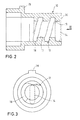
- the control member 5 consists of a drive element 9 and a rotationally fixed with this connected actuating element 10, which is arranged within the drive element 9 and is axially displaceable relative to this.
- the actuating element 10 has its side facing the locking element 6 has a thread 11 into which the first End 12 of a slidably arranged in a transverse bore 13 of the locking element 6 Control pin 14 engages, the second end 15 radially through the thread 16 opposite inner wall 17 of the actuating element 10 is positively guided.
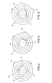
- the inner wall 17 of the actuating element 10 has in the region of the two thread ends 18, 19 (Fig.2) a contour on (Fig.3), which is designed such that the through the inner wall 17 positively driven control pin 14 performs a freewheel in these areas, if the actuating element 10 after reaching the locking or unlocking position of the Locking element rotates further in the corresponding direction.
- the control pin 14 in the direction of its longitudinal axis 20 back and forth (see also Fig. 3-6; the Control pin 14 is shown in dashed lines in these figures).
- the actuating element 10 has one on its side facing away from the steering spindle 2 axially displaceable cover 21 (FIG. 1), on which there is an actuating element 10 and drive element 9 arranged compression spring 22 supports.
- the length of the thread 11 is chosen such that after reaching the locking position of the locking element 6 of the control pin 14 is still within the thread 11 and the actuating element 10 or the locking element 6 even after reaching the locking position axially moved to generate a bias of the compression spring 22 can be.
- the locking element 6 may be in the locking position shown in FIG. 1 are so that its front end 7 in one by two adjacent teeth 23 formed locking groove 24 of a ring gear 25 attached to the steering shaft 2 engages and the actuating element 10 is displaced in the direction of the compression spring 22 and therefore biases the spring.
- the electric motor 40 If the electric motor 40 is now activated to move the locking element 6 into its unlocked position to move, the electric motor 40 rotates the drive element via a drive pinion 26 9, which has an external toothing 27 on the circumference for this purpose.
- the rotary motion of the drive element 9 is arranged on the actuating element 10 Projection 28, which in a corresponding axial longitudinal groove 29 of the drive element 9 engages, transferred to the actuator 10. This will make the actuator 10 moved helically along the locking element 6 until it with his front end face 30 abuts a first stop 31 fixed to the housing.
- the electric motor 40 is activated again, whereby the drive pinion 26 and thus also the control member 5 in the opposite direction be rotated.
- the control bolt is actuated by the pressure of the prestressed compression spring 22 14 pressed into the thread 11 of the rotating actuator 10, so that the locking element 6 is moved into its locked position.
- the actuator is located 10 first at the first stop 31.
- the actuating element 10 is in as long Moved towards the compression spring 22 until the control pin 14, the threaded end 18th (Fig.2) has reached and the actuating element 10 in turn performs a freewheel (the Sequence of movements of the control pin corresponds to the sequence shown in Fig. 3-6). Then the electric motor is e.g. by another, not shown Touch switch switched off.
Applications Claiming Priority (2)
| Application Number | Priority Date | Filing Date | Title |
|---|---|---|---|
| DE19961975 | 1999-12-22 | ||
| DE19961975A DE19961975C1 (de) | 1999-12-22 | 1999-12-22 | Verriegelungsvorrichtung |
Publications (3)
| Publication Number | Publication Date |
|---|---|
| EP1110828A2 true EP1110828A2 (fr) | 2001-06-27 |
| EP1110828A3 EP1110828A3 (fr) | 2003-08-27 |
| EP1110828B1 EP1110828B1 (fr) | 2004-12-01 |
Family
ID=7933783
Family Applications (1)
| Application Number | Title | Priority Date | Filing Date |
|---|---|---|---|
| EP00403192A Expired - Lifetime EP1110828B1 (fr) | 1999-12-22 | 2000-11-16 | Dispositif de verrouillage |
Country Status (5)
| Country | Link |
|---|---|
| US (1) | US20010025516A1 (fr) |
| EP (1) | EP1110828B1 (fr) |
| JP (1) | JP4698019B2 (fr) |
| DE (2) | DE19961975C1 (fr) |
| ES (1) | ES2234544T3 (fr) |
Cited By (4)
| Publication number | Priority date | Publication date | Assignee | Title |
|---|---|---|---|---|
| EP1281589A2 (fr) * | 2001-07-25 | 2003-02-05 | Conti Temic microelectronic GmbH | Dispositif de verrouillage |
| WO2006027048A1 (fr) * | 2004-09-10 | 2006-03-16 | Huf Hülsbeck & Fürst Gmbh & Co. Kg | Dispositif pour empecher la rotation de l'arbre de rotation d'un vehicule automobile |
| EP3162642A1 (fr) * | 2015-10-27 | 2017-05-03 | Asahi Denso Co., Ltd. | Dispositif de verrouillage de direction |
| EP3287330A1 (fr) * | 2016-08-23 | 2018-02-28 | HUF Hülsbeck & Fürst GmbH & Co. KG | Dispositif de verrouillage pour une colonne de direction d'un véhicule automobile et colonne de direction pourvue de dispositif de verrouillage |
Families Citing this family (24)
| Publication number | Priority date | Publication date | Assignee | Title |
|---|---|---|---|---|
| DE10103182B4 (de) * | 2001-01-24 | 2012-09-27 | Valeo Sicherheitssysteme Gmbh | Verriegelungsvorrichtung |
| DE10109609C1 (de) * | 2001-02-28 | 2002-10-10 | Huf Huelsbeck & Fuerst Gmbh | Schloß, insbesondere zum Verriegeln der Lenkspindel eines Kraftfahrzeugs |
| DE10121714C1 (de) | 2001-05-04 | 2003-01-02 | Huf Huelsbeck & Fuerst Gmbh | Schloß, insbesondere zum Verriegeln der Lenkspindel eines Kraftfahrzeugs |
| JP3808789B2 (ja) * | 2002-03-22 | 2006-08-16 | 株式会社東海理化電機製作所 | 電動ステアリングロック装置 |
| JP3811416B2 (ja) * | 2002-03-22 | 2006-08-23 | 株式会社東海理化電機製作所 | 電動ステアリングロック装置 |
| JP4038132B2 (ja) * | 2003-01-31 | 2008-01-23 | 株式会社東海理化電機製作所 | 電動ステアリングロック装置 |
| DE10320138B3 (de) * | 2003-05-06 | 2005-01-13 | Huf Hülsbeck & Fürst Gmbh & Co. Kg | Vorrichtung zum Sperren der Lenkspindel eines Kraftfahrzeugs |
| US7140213B2 (en) * | 2004-02-21 | 2006-11-28 | Strattec Security Corporation | Steering column lock apparatus and method |
| US7065993B2 (en) * | 2004-06-04 | 2006-06-27 | U-Shin Ltd. | Motor-driven steering lock device |
| EP1799528A4 (fr) * | 2004-09-09 | 2009-11-04 | Stoneridge Control Devices Inc | Actionneur de verrouillage d'arbre de direction |
| JP2006273115A (ja) * | 2005-03-29 | 2006-10-12 | Alpha Corp | 電動ステアリングロック装置及び電動ステアリングロック装置の制御方法 |
| JP2007145063A (ja) * | 2005-11-24 | 2007-06-14 | Yuhshin Co Ltd | 電動ステアリングロック装置 |
| US7762110B2 (en) * | 2006-10-06 | 2010-07-27 | U-Shin, Ltd. | Steering lock unit |
| US7870768B2 (en) * | 2006-10-27 | 2011-01-18 | U-Shin Ltd. | Power steering lock unit |
| DE102006058759A1 (de) * | 2006-12-12 | 2008-06-19 | Huf Hülsbeck & Fürst Gmbh & Co. Kg | Vorrichtung zur Ansteuerung eines Sperrgliedes |
| DE102007059712A1 (de) * | 2007-12-10 | 2009-06-25 | Huf Hülsbeck & Fürst Gmbh & Co. Kg | Vorrichtung zur Ansteuerung eines Sperrgliedes |
| CN101952145A (zh) * | 2008-02-14 | 2011-01-19 | 冯建中 | 车辆方向盘锁死防盗装置 |
| KR101334956B1 (ko) * | 2011-10-10 | 2013-12-05 | 주식회사 대동 | 차량의 전동식 스테어링 락 장치 및 그 조립방법 |
| CN105593079B (zh) * | 2013-10-04 | 2017-11-21 | 株式会社阿尔发 | 电动转向锁定装置 |
| US9221427B2 (en) * | 2014-02-11 | 2015-12-29 | Steering Solutions Ip Holding Corporation | System for selectively locking a steering column |
| US9731681B2 (en) * | 2014-04-29 | 2017-08-15 | Strattec Security Corporation | Steering lock |
| CN107676359A (zh) * | 2016-08-02 | 2018-02-09 | 上海圣享科技股份有限公司 | 螺接装置及其控制装置和控制方法 |
| JP2018203178A (ja) * | 2017-06-08 | 2018-12-27 | 株式会社アルファ | 電動ステアリングロック装置 |
| CN114570779A (zh) * | 2022-02-10 | 2022-06-03 | 马鞍山尊马科技有限公司 | 一种钢管制造内壁处理装置 |
Citations (1)
| Publication number | Priority date | Publication date | Assignee | Title |
|---|---|---|---|---|
| DE4436326C1 (de) | 1994-10-11 | 1995-10-19 | Huelsbeck & Fuerst | Schloß, insbesondere zum Verriegeln der Lenkspindel oder der Zahnstange des Lenkgetriebes oder der Ausgangswelle des Antriebsgetriebes eines Kraftfahrzeugs |
Family Cites Families (1)
| Publication number | Priority date | Publication date | Assignee | Title |
|---|---|---|---|---|
| FR2739073B1 (fr) * | 1995-09-21 | 1997-10-24 | Valeo Securite Habitacle | Antivol electrique motorise de direction de vehicule automobile |
-
1999
- 1999-12-22 DE DE19961975A patent/DE19961975C1/de not_active Expired - Fee Related
-
2000
- 2000-11-16 DE DE50008824T patent/DE50008824D1/de not_active Expired - Lifetime
- 2000-11-16 ES ES00403192T patent/ES2234544T3/es not_active Expired - Lifetime
- 2000-11-16 EP EP00403192A patent/EP1110828B1/fr not_active Expired - Lifetime
- 2000-12-18 JP JP2000383531A patent/JP4698019B2/ja not_active Expired - Fee Related
- 2000-12-19 US US09/739,304 patent/US20010025516A1/en not_active Abandoned
Patent Citations (1)
| Publication number | Priority date | Publication date | Assignee | Title |
|---|---|---|---|---|
| DE4436326C1 (de) | 1994-10-11 | 1995-10-19 | Huelsbeck & Fuerst | Schloß, insbesondere zum Verriegeln der Lenkspindel oder der Zahnstange des Lenkgetriebes oder der Ausgangswelle des Antriebsgetriebes eines Kraftfahrzeugs |
Cited By (12)
| Publication number | Priority date | Publication date | Assignee | Title |
|---|---|---|---|---|
| EP1281589A2 (fr) * | 2001-07-25 | 2003-02-05 | Conti Temic microelectronic GmbH | Dispositif de verrouillage |
| EP1281589A3 (fr) * | 2001-07-25 | 2004-07-28 | Conti Temic microelectronic GmbH | Dispositif de verrouillage |
| WO2006027048A1 (fr) * | 2004-09-10 | 2006-03-16 | Huf Hülsbeck & Fürst Gmbh & Co. Kg | Dispositif pour empecher la rotation de l'arbre de rotation d'un vehicule automobile |
| US7604254B2 (en) | 2004-09-10 | 2009-10-20 | Huf Hülsbeck & Fürst GmbH & Co KG | Device for blocking the steering shaft of a motor vehicle |
| KR100928894B1 (ko) * | 2004-09-10 | 2009-11-30 | 후프 휠스베크 운트 휘르스트 게엠베하 운트 코 카게 | 자동차의 조향축 차단 장치 |
| CN101052554B (zh) * | 2004-09-10 | 2010-05-05 | 胡夫许尔斯贝克&菲尔斯特两合公司 | 用于锁止机动车的转向轴的装置 |
| EP3162642A1 (fr) * | 2015-10-27 | 2017-05-03 | Asahi Denso Co., Ltd. | Dispositif de verrouillage de direction |
| US9889817B2 (en) | 2015-10-27 | 2018-02-13 | Asahi Denso Co., Ltd. | Steering lock device |
| EP3287330A1 (fr) * | 2016-08-23 | 2018-02-28 | HUF Hülsbeck & Fürst GmbH & Co. KG | Dispositif de verrouillage pour une colonne de direction d'un véhicule automobile et colonne de direction pourvue de dispositif de verrouillage |
| CN107757552A (zh) * | 2016-08-23 | 2018-03-06 | 胡夫·许尔斯贝克和福斯特有限及两合公司 | 用于机动车的转向柱的锁定设备和带有锁定设备的转向柱 |
| EP3659874A1 (fr) * | 2016-08-23 | 2020-06-03 | Huf Hülsbeck & Fürst GmbH & Co. KG | Dispositif de verrouillage pour une colonne de direction d'un véhicule automobile et colonne de direction pourvue de dispositif de verrouillage |
| CN107757552B (zh) * | 2016-08-23 | 2021-12-28 | 胡夫·许尔斯贝克和福斯特有限及两合公司 | 用于机动车的转向柱的锁定设备和带有锁定设备的转向柱 |
Also Published As
| Publication number | Publication date |
|---|---|
| ES2234544T3 (es) | 2005-07-01 |
| EP1110828B1 (fr) | 2004-12-01 |
| JP4698019B2 (ja) | 2011-06-08 |
| DE19961975C1 (de) | 2000-12-14 |
| JP2001241240A (ja) | 2001-09-04 |
| US20010025516A1 (en) | 2001-10-04 |
| DE50008824D1 (de) | 2005-01-05 |
| EP1110828A3 (fr) | 2003-08-27 |
Similar Documents
| Publication | Publication Date | Title |
|---|---|---|
| EP1110828B1 (fr) | Dispositif de verrouillage | |
| EP1363815B1 (fr) | Serrure, servant notamment a verrouiller l'arbre de direction d'une automobile | |
| EP1167134B1 (fr) | Verrou, notamment destiné au verrouillage de la colonne ou la crémaillère de direction ou de l'arbre de sortie de la transmission d'un véhicule à moteur | |
| EP1232921B1 (fr) | Système de verouillage | |
| DE10233511A1 (de) | Schließsystem für Motorfahrzeuge | |
| DE102010018243B4 (de) | Schließzylinderanordnung | |
| EP0846602B1 (fr) | Dispositif de commande pour au moins un verrou de blockage et son utilisation dans un antivol de direction pour automobile | |
| EP0666399A1 (fr) | Dispositif d'entraînement pour un élément d'un véhicule pouvant se déplacer entre des positions finales | |
| EP3775625A1 (fr) | Unité de commande de frein de stationnement et unité de frein de stationnement équipée de celle-ci | |
| DE102007059710B4 (de) | Kompakte Verriegelungsvorrichtung mit Sicherungselement | |
| DE3127484C2 (de) | Schließzylinder mit axial beweglichem Sperrzapfen | |
| EP0482588A1 (fr) | Serrure de porte commandée par moteur électrique | |
| EP0721869B1 (fr) | Dispositif de verrouillage pour véhicules | |
| DE2632908B2 (de) | Kraftfahrzeug-Lenkschloß | |
| DE10017032B4 (de) | Vorrichtung zur Ver- und Entriegelung der Lenkspindel einer Lenkeinrichtung | |
| DE4120194C2 (fr) | ||
| DE19906268C2 (de) | Vorrichtung zur elektrischen Verriegelung der Lenkspindel einer Lenkeinrichtung | |
| DE1953685B2 (de) | LenkschloB für Kraftfahrzeuge | |
| DE19532590A1 (de) | Motor- und handbetätigbarer Stellantrieb | |
| EP3957813A1 (fr) | Dispositif d'entraînement et porte coulissante | |
| DE4302846A1 (de) | Automatisierte Betätigungseinrichtung für eine Anfahr-/Schaltkupplung | |
| DE102016015728A1 (de) | Parksperren-Aktuatoreinheit | |
| EP1182103B1 (fr) | Dispositif de verrouillage pour la colonne de direction d'un véhicule | |
| EP0791707B1 (fr) | Serrure pour véhicule automobile | |
| DE102019128563A1 (de) | Elektromechanischer Parksperrenaktuator |
Legal Events
| Date | Code | Title | Description |
|---|---|---|---|
| PUAI | Public reference made under article 153(3) epc to a published international application that has entered the european phase |
Free format text: ORIGINAL CODE: 0009012 |
|
| AK | Designated contracting states |
Kind code of ref document: A2 Designated state(s): AT BE CH CY DE DK ES FI FR GB GR IE IT LI LU MC NL PT SE TR |
|
| AX | Request for extension of the european patent |
Free format text: AL;LT;LV;MK;RO;SI |
|
| PUAL | Search report despatched |
Free format text: ORIGINAL CODE: 0009013 |
|
| AK | Designated contracting states |
Designated state(s): AT BE CH CY DE DK ES FI FR GB GR IE IT LI LU MC NL PT SE TR |
|
| AX | Request for extension of the european patent |
Extension state: AL LT LV MK RO SI |
|
| RIC1 | Information provided on ipc code assigned before grant |
Ipc: 7E 05B 65/12 B Ipc: 7B 60R 25/02 A |
|
| GRAP | Despatch of communication of intention to grant a patent |
Free format text: ORIGINAL CODE: EPIDOSNIGR1 |
|
| 17P | Request for examination filed |
Effective date: 20040227 |
|
| AKX | Designation fees paid |
Designated state(s): DE ES FR GB IT |
|
| RAP1 | Party data changed (applicant data changed or rights of an application transferred) |
Owner name: VALEO SICHERHEITSSYSTEME GMBH |
|
| GRAS | Grant fee paid |
Free format text: ORIGINAL CODE: EPIDOSNIGR3 |
|
| GRAA | (expected) grant |
Free format text: ORIGINAL CODE: 0009210 |
|
| AK | Designated contracting states |
Kind code of ref document: B1 Designated state(s): DE ES FR GB IT |
|
| PG25 | Lapsed in a contracting state [announced via postgrant information from national office to epo] |
Ref country code: GB Free format text: LAPSE BECAUSE OF FAILURE TO SUBMIT A TRANSLATION OF THE DESCRIPTION OR TO PAY THE FEE WITHIN THE PRESCRIBED TIME-LIMIT Effective date: 20041201 |
|
| REG | Reference to a national code |
Ref country code: GB Ref legal event code: FG4D Free format text: NOT ENGLISH |
|
| REG | Reference to a national code |
Ref country code: IE Ref legal event code: FG4D Free format text: GERMAN |
|
| REF | Corresponds to: |
Ref document number: 50008824 Country of ref document: DE Date of ref document: 20050105 Kind code of ref document: P |
|
| ET | Fr: translation filed | ||
| GBV | Gb: ep patent (uk) treated as always having been void in accordance with gb section 77(7)/1977 [no translation filed] |
Effective date: 20041201 |
|
| REG | Reference to a national code |
Ref country code: ES Ref legal event code: FG2A Ref document number: 2234544 Country of ref document: ES Kind code of ref document: T3 |
|
| PLBE | No opposition filed within time limit |
Free format text: ORIGINAL CODE: 0009261 |
|
| STAA | Information on the status of an ep patent application or granted ep patent |
Free format text: STATUS: NO OPPOSITION FILED WITHIN TIME LIMIT |
|
| 26N | No opposition filed |
Effective date: 20050902 |
|
| REG | Reference to a national code |
Ref country code: DE Ref legal event code: R082 Ref document number: 50008824 Country of ref document: DE Representative=s name: PODSZUS, BURGHART, DIPL.-PHYS. DIPL.-WIRTSCH.-, DE |
|
| REG | Reference to a national code |
Ref country code: DE Ref legal event code: R082 Ref document number: 50008824 Country of ref document: DE Effective date: 20141219 Representative=s name: PODSZUS, BURGHART, DIPL.-PHYS. DIPL.-WIRTSCH.-, DE Ref country code: DE Ref legal event code: R081 Ref document number: 50008824 Country of ref document: DE Owner name: U-SHIN DEUTSCHLAND ZUGANGSSYSTEME GMBH, DE Free format text: FORMER OWNER: VALEO SICHERHEITSSYSTEME GMBH, 85253 ERDWEG, DE Effective date: 20141219 |
|
| PGFP | Annual fee paid to national office [announced via postgrant information from national office to epo] |
Ref country code: ES Payment date: 20141124 Year of fee payment: 15 Ref country code: DE Payment date: 20141113 Year of fee payment: 15 |
|
| PGFP | Annual fee paid to national office [announced via postgrant information from national office to epo] |
Ref country code: FR Payment date: 20141201 Year of fee payment: 15 |
|
| PGFP | Annual fee paid to national office [announced via postgrant information from national office to epo] |
Ref country code: IT Payment date: 20141113 Year of fee payment: 15 |
|
| REG | Reference to a national code |
Ref country code: DE Ref legal event code: R082 Ref document number: 50008824 Country of ref document: DE |
|
| REG | Reference to a national code |
Ref country code: ES Ref legal event code: PC2A Owner name: U-SHIN DEUTSCHLAND ZUGANGSSYSTEME GMBH Effective date: 20150618 |
|
| REG | Reference to a national code |
Ref country code: DE Ref legal event code: R119 Ref document number: 50008824 Country of ref document: DE |
|
| PG25 | Lapsed in a contracting state [announced via postgrant information from national office to epo] |
Ref country code: IT Free format text: LAPSE BECAUSE OF NON-PAYMENT OF DUE FEES Effective date: 20151116 |
|
| REG | Reference to a national code |
Ref country code: FR Ref legal event code: ST Effective date: 20160729 |
|
| PG25 | Lapsed in a contracting state [announced via postgrant information from national office to epo] |
Ref country code: DE Free format text: LAPSE BECAUSE OF NON-PAYMENT OF DUE FEES Effective date: 20160601 |
|
| PG25 | Lapsed in a contracting state [announced via postgrant information from national office to epo] |
Ref country code: FR Free format text: LAPSE BECAUSE OF NON-PAYMENT OF DUE FEES Effective date: 20151130 |
|
| REG | Reference to a national code |
Ref country code: ES Ref legal event code: FD2A Effective date: 20161227 |
|
| PG25 | Lapsed in a contracting state [announced via postgrant information from national office to epo] |
Ref country code: ES Free format text: LAPSE BECAUSE OF NON-PAYMENT OF DUE FEES Effective date: 20151117 |