EP2072434A2 - Blattfördervorrichtung und Bilderzeugungsvorrichtung damit - Google Patents
Blattfördervorrichtung und Bilderzeugungsvorrichtung damit Download PDFInfo
- Publication number
- EP2072434A2 EP2072434A2 EP08170007A EP08170007A EP2072434A2 EP 2072434 A2 EP2072434 A2 EP 2072434A2 EP 08170007 A EP08170007 A EP 08170007A EP 08170007 A EP08170007 A EP 08170007A EP 2072434 A2 EP2072434 A2 EP 2072434A2
- Authority
- EP
- European Patent Office
- Prior art keywords
- sheet
- guide
- sheet conveyance
- skew
- conveyance
- Prior art date
- Legal status (The legal status is an assumption and is not a legal conclusion. Google has not performed a legal analysis and makes no representation as to the accuracy of the status listed.)
- Withdrawn
Links
- 230000007246 mechanism Effects 0.000 claims abstract description 36
- 238000001514 detection method Methods 0.000 claims description 32
- 238000011144 upstream manufacturing Methods 0.000 claims description 15
- 230000001105 regulatory effect Effects 0.000 claims description 4
- 238000005452 bending Methods 0.000 claims description 3
- 238000012937 correction Methods 0.000 description 133
- 238000012546 transfer Methods 0.000 description 40
- 238000012545 processing Methods 0.000 description 18
- 238000000034 method Methods 0.000 description 17
- 230000008859 change Effects 0.000 description 10
- 239000000463 material Substances 0.000 description 10
- 238000003825 pressing Methods 0.000 description 10
- 230000015572 biosynthetic process Effects 0.000 description 7
- 238000007639 printing Methods 0.000 description 7
- 230000006870 function Effects 0.000 description 6
- 230000007423 decrease Effects 0.000 description 4
- 238000010586 diagram Methods 0.000 description 4
- 239000003086 colorant Substances 0.000 description 3
- 230000001276 controlling effect Effects 0.000 description 3
- 238000006073 displacement reaction Methods 0.000 description 3
- 230000008569 process Effects 0.000 description 3
- 230000000694 effects Effects 0.000 description 2
- 230000002708 enhancing effect Effects 0.000 description 2
- 238000004519 manufacturing process Methods 0.000 description 2
- 238000007645 offset printing Methods 0.000 description 2
- 239000002245 particle Substances 0.000 description 2
- 229920006324 polyoxymethylene Polymers 0.000 description 2
- 239000011347 resin Substances 0.000 description 2
- 229920005989 resin Polymers 0.000 description 2
- 229930182556 Polyacetal Natural products 0.000 description 1
- 238000006243 chemical reaction Methods 0.000 description 1
- 238000004891 communication Methods 0.000 description 1
- 230000008878 coupling Effects 0.000 description 1
- 238000010168 coupling process Methods 0.000 description 1
- 238000005859 coupling reaction Methods 0.000 description 1
- 230000003247 decreasing effect Effects 0.000 description 1
- 230000003111 delayed effect Effects 0.000 description 1
- 238000011161 development Methods 0.000 description 1
- 238000012840 feeding operation Methods 0.000 description 1
- 229910052736 halogen Inorganic materials 0.000 description 1
- 150000002367 halogens Chemical class 0.000 description 1
- 238000005259 measurement Methods 0.000 description 1
- 238000012986 modification Methods 0.000 description 1
- 230000004048 modification Effects 0.000 description 1
- 230000003287 optical effect Effects 0.000 description 1
- 230000002093 peripheral effect Effects 0.000 description 1
- 230000004044 response Effects 0.000 description 1
Images







Classifications
-
- B—PERFORMING OPERATIONS; TRANSPORTING
- B65—CONVEYING; PACKING; STORING; HANDLING THIN OR FILAMENTARY MATERIAL
- B65H—HANDLING THIN OR FILAMENTARY MATERIAL, e.g. SHEETS, WEBS, CABLES
- B65H9/00—Registering, e.g. orientating, articles; Devices therefor
- B65H9/16—Inclined tape, roller, or like article-forwarding side registers
- B65H9/166—Roller
-
- G—PHYSICS
- G03—PHOTOGRAPHY; CINEMATOGRAPHY; ANALOGOUS TECHNIQUES USING WAVES OTHER THAN OPTICAL WAVES; ELECTROGRAPHY; HOLOGRAPHY
- G03G—ELECTROGRAPHY; ELECTROPHOTOGRAPHY; MAGNETOGRAPHY
- G03G15/00—Apparatus for electrographic processes using a charge pattern
-
- B—PERFORMING OPERATIONS; TRANSPORTING
- B65—CONVEYING; PACKING; STORING; HANDLING THIN OR FILAMENTARY MATERIAL
- B65H—HANDLING THIN OR FILAMENTARY MATERIAL, e.g. SHEETS, WEBS, CABLES
- B65H5/00—Feeding articles separated from piles; Feeding articles to machines
- B65H5/36—Article guides or smoothers, e.g. movable in operation
- B65H5/38—Article guides or smoothers, e.g. movable in operation immovable in operation
-
- B—PERFORMING OPERATIONS; TRANSPORTING
- B65—CONVEYING; PACKING; STORING; HANDLING THIN OR FILAMENTARY MATERIAL
- B65H—HANDLING THIN OR FILAMENTARY MATERIAL, e.g. SHEETS, WEBS, CABLES
- B65H2301/00—Handling processes for sheets or webs
- B65H2301/50—Auxiliary process performed during handling process
- B65H2301/51—Modifying a characteristic of handled material
- B65H2301/512—Changing form of handled material
- B65H2301/5122—Corrugating; Stiffening
-
- B—PERFORMING OPERATIONS; TRANSPORTING
- B65—CONVEYING; PACKING; STORING; HANDLING THIN OR FILAMENTARY MATERIAL
- B65H—HANDLING THIN OR FILAMENTARY MATERIAL, e.g. SHEETS, WEBS, CABLES
- B65H2404/00—Parts for transporting or guiding the handled material
- B65H2404/10—Rollers
- B65H2404/14—Roller pairs
- B65H2404/142—Roller pairs arranged on movable frame
- B65H2404/1424—Roller pairs arranged on movable frame moving in parallel to their axis
-
- B—PERFORMING OPERATIONS; TRANSPORTING
- B65—CONVEYING; PACKING; STORING; HANDLING THIN OR FILAMENTARY MATERIAL
- B65H—HANDLING THIN OR FILAMENTARY MATERIAL, e.g. SHEETS, WEBS, CABLES
- B65H2404/00—Parts for transporting or guiding the handled material
- B65H2404/60—Other elements in face contact with handled material
- B65H2404/69—Other means designated for special purpose
- B65H2404/696—Ball, sphere
Definitions
- the present invention relates to a sheet conveyance apparatus for a printer, a facsimile machine, a copying machine, or a multifunction peripheral having a plurality of functions, and further relates to an image forming apparatus including the sheet conveyance apparatus.
- a conventional electrophotographic color image forming apparatus includes a plurality of photosensitive drums disposed in a straight line (referred to as “tandem type") or disposed along a circular path (referred to as "rotary type").
- a method for directly transferring a toner image from a photosensitive drum to a sheet is referred to as a "direct transfer method”.
- a method for transferring a toner image from a photosensitive drum to an intermediate transfer member and then transferring the toner image from the intermediate transfer member to a sheet is referred to as an "intermediate transfer method.”
- image forming apparatuses are advantageous in not requiring printing plates and are preferably used for Print On Demand (POD) services, according to which a small amount of printing can be flexibly performed.
- POD Print On Demand
- image forming apparatuses dedicated to the POD services are required to perform high performances suitable for the POD services.
- accuracy in positioning an image on a sheet is an important factor to be satisfied.
- the image positioning accuracy includes an accuracy of positional adjustment between images formed on front and reverse pages.
- the position in a sheet conveyance direction, the position in a direction perpendicular to the sheet conveyance direction, a magnification rate of the image, and a skew amount of the sheet are example factors influencing the position of an image formed on a sheet. Thus, eliminating differences in these factors is a key to attain a satisfactory level of positioning accuracy.
- an image forming apparatus can perform electrical control to eliminate differences in the sheet conveyance position and the magnification of an image.
- correcting the skew of a sheet using electrical control is difficult.
- the apparatus can electrically control irradiation timing/position of a laser beam based on an image signal supplied to a photosensitive drum.
- the apparatus can electrically control the irradiation range of the laser beam emitted to the photosensitive drum.
- the skew correction mechanisms are roughly classified into the following types (or groups).
- a skew correction mechanism belonging to a general type includes a pair of registration rollers disposed on the upstream side of a transfer unit, which can eliminate a skew amount of a conveyed sheet (conveyed transfer material) by causing the leading edge of the sheet to collide against a nip portion of the registration rollers in a stopped state.
- This type of skew correction mechanism excessively conveys a sheet after the leading edge of the sheet reaches the nip portion of the registration rollers. Therefore, while the conveyed sheet deforms into a loop shape, the leading edge of the sheet can be aligned along the nip portion of the registration rollers so as to eliminate a skew amount.
- a skew correction mechanism belonging to another type includes a calculation unit configured to calculate a skew amount of a sheet based on a detected inclination of the leading edge of the sheet and two independently driven rollers disposed in a direction perpendicular to the sheet conveyance direction.
- This type of skew correction mechanism independently changes the conveyance speed of each driving roller according to a calculated skew amount of a sheet, thereby causing the sheet to rotate in a predetermined direction to eliminate the skew.
- a skew correction mechanism belonging to yet another type includes a reference surface extending along the sheet conveyance direction and skew rollers obliquely conveying a sheet toward the reference surface.
- the reference surface causes a conveyed sheet to change its orientation (reduce a skew amount) while regulating the side edge of the conveyed sheet.
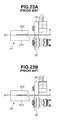
- Figs. 23A and 23B illustrate a skew correction unit as seen from a sheet conveyance direction, according to which a sheet moves from the front side to the rear side of the drawing.
- the skew correction unit includes a skew correction roller 32 and a pressing roller 34, which can cooperatively hold a sheet S and obliquely convey the sheet S to a reference surface 311 of a reference guide unit 31. After the sheet S collides against the reference surface 311, the skew correction roller 32 and the pressing roller 34 cause the sheet S to rotate to change its orientation (reduces a skew amount) and start moving straight along the reference surface 311.
- a side edge of the sheet S is obliquely conveyed between the skew correction roller 32 and the pressing roller 34, the sheet S is guided by an upper guide 312 and a lower guide 313 of the reference guide unit 31.
- the upper guide 312 and the lower guide 313 prevent the sheet S from buckling.
- the method for correcting the skew of a sheet by causing a side edge of the sheet to change its orientation along a reference surface is advantageous in the following points.
- an image forming apparatus When an image forming apparatus performs image formation processing on front and reverse sides (first and second pages) of a sheet, the image forming apparatus performs a switchback operation to switch leading/trailing edges of the sheet for the first and second pages. In this case, the apparatus does not switch the side edges of the sheet.
- the apparatus performs the skew correction on the first and second pages of a sheet similarly at the same position in a direction perpendicular to the sheet conveyance direction. Therefore, the skew correction method using a reference surface can accurately set a start position of an image relative to a side edge of a sheet.
- the apparatus can perform two-sided image formation processing without causing any deviation between images on the front and reverse sides of a sheet.
- a deviation between images on the first and second pages cannot be corrected if the deviation is caused in a direction perpendicular to the sheet conveyance direction. Namely, even if the skew correction ability is high, images formed on the front and reverse sides of a sheet may deviate relative to a side edge of the sheet.
- image forming apparatuses are required to perform image formation on various types of recording materials, including plain paper different in grammage (e.g., not less than 40 g/m 2 and not greater than 350 g/m 2 ), coated sheet, film, and other special materials.
- a representative skew correction method includes conveying a sheet obliquely toward a reference surface to cause the conveyed sheet to collide at its side edge against the reference surface and change its orientation so as to reduce a skew amount of the sheet.
- recent image forming apparatuses are required to use various types of sheets different in thickness and material. If a conveyed sheet is thin or made of a material having a lower stiffness, the sheet may buckle when it collides against the reference surface. As illustrated in Fig. 23B , if the sheet S has a lower stiffness, the sheet S may buckle in a clearance between the upper guide 312 and the lower guide 313 when the sheet S collides against the reference surface 311.
- the skew correction cannot be performed accurately and accuracy in positioning an image on a sheet deteriorates correspondingly. Furthermore, paper jam may occur due to buckling of a sheet. The side edge of a sheet may be broken or damaged.
- the clearance between the upper guide 312 and the lower guide 313 is set to be larger than the thickness of a thickest sheet processed by the image forming apparatus. Therefore, the clearance between the upper guide 312 and the lower guide 313 is not sufficiently narrow to prevent a thin sheet from buckling.
- an apparatus discussed in Japanese Patent Application Laid-Open No. 2002-356250 includes a mechanism for adjusting the clearance between upper and lower guides according to the thickness of a sheet.
- the discussed conventional apparatus is operative to decrease the clearance between the upper and lower guides when the conveyed sheet is a thin sheet (i.e., a sheet having a lower stiffness). Therefore, the apparatus can surely guide the side edge of a sheet along the reference surface while preventing the sheet from buckling.
- a detection unit is required to operate accurately.
- the detection unit is, for example, a contact-type sensor or a reflection-type optical sensor capable of directly detecting the thickness of a sheet.
- Another detection unit can detect the thickness of a sheet based on the displacement of a conveyance roller movable when it nips the sheet.
- Fig. 22 is a graph illustrating plots representing various types of sheets with respect to a relationship between the thickness of a sheet and the stiffness of the sheet. As understood from the data illustrated in Fig. 22 , the stiffness of a specific type of sheet is greatly different from the stiffness of another type of sheet even if these sheets are similar in thickness.
- Exemplary embodiments of the present invention are directed to a sheet conveyance apparatus capable of conveying various types of sheets different in stiffness and surely correcting the skew of each conveyed sheet without using a complicated arrangement and also capable of preventing a sheet from buckling when the sheet collides against a reference surface.
- Fig. 1 illustrates a side view of an example skew correction apparatus according to an exemplary embodiment of the present invention.
- Fig. 2 illustrates a perspective view of the skew correction apparatus illustrated in Fig. 1 .
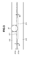
- Fig. 3 illustrates an enlarged cross-sectional view of a reference guide unit illustrated in Fig. 1 .
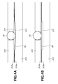
- Figs. 4A and 4B are enlarged views illustrating example operational states of the reference guide unit illustrated in Fig. 3 .
- Fig. 5 illustrates a plan view of the skew correction apparatus illustrated in Fig. 1 .
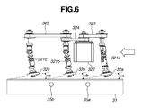
- Fig. 6 illustrates a plan view of the skew correction apparatus illustrated in Fig. 1 .
- Fig. 7 illustrates a cross-sectional view of an example image forming apparatus including a skew correction apparatus according to an example embodiment of the present invention.
- Figs. 8A to 8D illustrate plan views of an example registration unit illustrated in Fig. 7 .
- Fig. 9 is a graph illustrating an example relationship among geometrical moment of inertia, sheet thickness, and guide altitudinal difference according to an exemplary embodiment of the present invention.
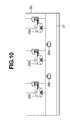
- Fig. 10 is a perspective view illustrating an example skew correction apparatus according to a second exemplary embodiment of the present invention.
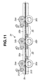
- Fig. 11 illustrates a side view of an example skew correction apparatus according to a third exemplary embodiment of the present invention.
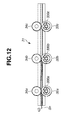
- Fig. 12 illustrates a side view of an example skew correction apparatus according to a fourth exemplary embodiment of the present invention.
- Fig. 13 is a block diagram of an example control system according to the fourth exemplary embodiment of the present invention.
- Fig. 14 is a flowchart illustrating an example operation performed by the control system illustrated in Fig. 13 .
- Fig. 15 illustrates a front view of an example skew correction apparatus according to a fifth exemplary embodiment of the present invention.
- Fig. 16 illustrates a perspective view of the skew correction apparatus illustrated in Fig. 15 .
- Fig. 17 illustrates an enlarged perspective view of the skew correction apparatus illustrated in Fig. 16 .
- Fig. 18A is a front view illustrating an example state when a thick paper is passing through the skew correction apparatus illustrated in Fig. 15 .
- Fig. 18B is a front view illustrating an example state when a thin paper is passing through the skew correction apparatus illustrated in Fig. 15 .
- Fig. 19 is a block diagram illustrating an example control unit for controlling the skew correction apparatus illustrated in Fig. 15 .
- Fig. 20 is a flowchart illustrating an example operation performed by the control unit illustrated in Fig. 19 .
- Fig. 21A is a front view illustrating an example state when a thick paper is passing through a skew correction apparatus according to a sixth exemplary embodiment of the present invention.
- Fig. 21B is a front view illustrating an example state when a thin paper is passing through the skew correction apparatus according to the sixth exemplary embodiment of the present invention.
- Fig. 22 is a graph illustrating an example relationship between sheet thickness and stiffness.
- Figs. 23A and 23B illustrate a conventional skew correction apparatus as seen from a sheet conveyance direction.
- An electrophotographic image forming apparatus 1 is described below with reference to Fig. 7 .
- a sheet feeding apparatus 10 can store a plurality of sheets S (each serving as a transfer material) mounted on a lift-up apparatus 11.
- a sheet feeder unit 12 starts a sheet feeding operation in synchronization with image formation timing of an image forming mechanism 90.
- the sheet feeder unit 12 is, for example, a friction type that includes a feeding roller to separate a sheet or an air type that can use a suction force to hold and separate a sheet.
- the sheet feeder unit 12 according to the first exemplary embodiment is an air type.
- the sheet S fed from the sheet feeder unit 12, passes a conveyance path provided in a conveyance unit 20 and reaches a registration unit 30.
- the registration unit 30 includes a skew correction apparatus configured to perform skew correction on each sheet S and timing correction for synchronizing the sheet S with an image transfer operation performed by a secondary transfer unit.
- the registration unit 30 conveys the sheet S to the secondary transfer unit.
- the secondary transfer unit includes an internal secondary transfer roller 43 and an external secondary transfer roller 44, which are opposed to each other to form a transfer nip portion.
- the secondary transfer unit can transfer a toner image (unfixed image) from an intermediate transfer belt 40 to the sheet S by applying a predetermined pressing force and an electrostatic load bias.
- An example image forming process for forming a toner image to be transferred to a sheet and conveying the sheet to the secondary transfer unit is described below.
- the image forming mechanism 90 includes photosensitive drums 91, exposure devices 93, developing units 92, primary transfer units 45, and photosensitive drum cleaners 95.
- Light emitted from the exposure device 93 based on an image information signal is reflected by a reflection unit 94 and reaches the photosensitive drum 91 having a surface uniformly charged beforehand by a charging unit and rotating in the counterclockwise direction.
- an electrostatic latent image is formed on the surface of the photosensitive drum 91.
- the developing unit 92 performs toner development processing, according to which an electrostatic latent image is developed as a toner image on the surface of the photosensitive drum 91 by applying a toner.
- the primary transfer unit 45 applies a predetermined pressing force and an electrostatic load bias to transfer the toner image to the intermediate transfer belt 40.
- the photosensitive drum cleaner 95 collects toner particles remaining on the surface of the photosensitive drum 91.
- the above-described image forming mechanism 90 includes four, i.e., yellow (Y), magenta (M), cyan (C), and black (Bk), image forming units, although the total number of colors is not limited to four and the order of color arrangement is not limited to Y ⁇ M ⁇ C ⁇ Bk.
- the intermediate transfer belt 40 is stretched around a driving roller 42, a tension roller 41, and the internal secondary transfer roller 43.
- the intermediate transfer belt 40 when driven by a motor, rotates in a direction indicated by an arrow B.
- Respective color images formed by parallel processing of the above-described Y, M, C, and Bk image forming units, are sequentially overlapped on an upstream toner image primarily transferred to the intermediate transfer belt 40. As a result, a full-color toner image is finally formed on the intermediate transfer belt 40 and conveyed to the secondary transfer unit.
- the secondary transfer unit can secondarily transfer a full-color toner image on the sheet S.
- a belt cleaner 46 collects toner particles remaining on the surface of the intermediate transfer belt 40.
- a pre-fixing conveyance device 51 conveys the sheet S to a fixing unit 50.
- the fixing unit 50 includes rollers or belts opposed to each other to apply a predetermined pressing force to the sheet S and a heat source (e.g., a halogen heater) to heat the sheet S to fuse and fix the toner on the sheet S.
- the sheet S with an image fixed thereon reaches a diverging conveyance device 60, which directly discharges the sheet S to a sheet discharge tray 61 or, if the apparatus performs two-sided image formation processing, conveys the sheet S to a reversing conveyance device 70.
- the reversing conveyance device 70 performs a switchback operation for reversing the front/back surfaces of the sheet S and switching leading/trailing edges of the sheet S. Then, the sheet S reaches to a two-sided conveyance device 80.
- the two-sided conveyance device 80 causes the sheet S to enter the conveyance unit 20 while avoiding interference with another sheet S fed from the sheet feeding apparatus 10.
- the sheet S is subjected to image formation processing for the second page in the same manner as the above-described processing for the first page.
- the image forming mechanism 90, the intermediate transfer belt 40, the secondary transfer unit (including the internal secondary transfer roller 43 and the external secondary transfer roller 44), and the fixing unit 50 constitute an image forming unit, which is configured to form an image on a sheet according to an exemplary embodiment.
- Fig. 8A illustrates an example arrangement of the skew correction apparatus provided in the registration unit 30, which can correct the skew of a sheet.
- the skew correction apparatus includes a movable guide 55 and a stationary guide 33.
- the movable guide 55 can move in a sheet width direction (i.e., in a direction perpendicular to the sheet conveyance direction) according to the size of the sheet S.
- the movable guide 55 includes a reference guide unit 31, a plurality of skew correction rollers 32a, 32b, and 32c, and pressing rollers 34a, 34b, and 34c, which are integrally movable.
- the pressing rollers 34a, 34b, and 34c can press the skew correction rollers 32a, 32b, and 32c.
- the stationary guide 33 which is fixed to an apparatus frame, can function as a conveyance guide for the sheet S.
- Fig. 1 illustrates a side view of the skew correction apparatus as seen from a direction perpendicular to the sheet conveyance direction.
- Fig. 2 illustrates a perspective view of the skew correction apparatus as seen from an obliquely upper position.
- Figs. 3 , 4A, and 4B are partly enlarged views of Fig. 1 .
- Fig. 5 illustrates a plan view of the skew correction apparatus illustrated in Fig. 1 , which does not include an upper guide 312 of the reference guide unit 31.
- the reference guide unit 31 of the skew correction apparatus has a grooved (U-shaped) cross section.
- the reference guide unit 31 includes a reference surface 311, an upper guide 312 serving as a first guide, and a lower guide 313 serving as a second guide.
- the reference surface 311 corrects the orientation of a sheet to eliminate a skew amount while guiding a side edge of the sheet.
- the reference surface 311 has a function of positioning or regulating the side edge of a sheet.
- the upper guide 312 includes a sheet conveyance surface 312a facing one surface (the upper surface side) of a conveyed sheet.
- the lower guide 313 includes a sheet conveyance surface 313a facing the other surface (the lower surface side) of the conveyed sheet.
- the upper guide 312 and the lower guide 313 can cooperatively guide a side edge of a sheet to the reference surface 311 and can prevent the sheet from buckling when the sheet collides against the reference surface 311.
- the skew correction rollers 32a, 32b, and 32c (functioning as a skew conveyance mechanism) are inclined at an angle ⁇ relative to the sheet conveyance direction.
- the skew correction rollers 32a, 32b, and 32c obliquely convey a sheet toward the reference surface 311 of the reference guide unit 31 to cause the side edge of the sheet to obliquely collide against the reference surface 311. Then, the skew correction rollers 32a, 32b, and 32c convey the sheet while the reference surface 311 guides the side edge of the conveyed sheet.
- a driving motor 322 drives the skew correction rollers 32a, 32b, and 32c disposed along the sheet conveyance direction via timing belts 323, 324, and 325 and coupling joints 321a, 321b, and 321c. This arrangement is effective to reduce differences in driving speed among the respective skew correction rollers 32a, 32b, and 32c.
- Figs. 1 to 6 illustrate an example sheet deforming unit configured to bend a side edge of a sheet when the sheet collides against the reference surface 311.
- the lower guide 313 has recessed portions 314 disposed at a plurality of ("two" according to the illustrated embodiment) positions along the sheet conveyance direction.
- the recessed portions 314 have smooth surfaces continuous to the sheet conveyance surface 313a of the lower guide 313.
- the leading edge of a conveyed sheet can easily pass the recessed portions 314.
- the upper guide 312 includes spherical members 35 (35a and 35b) provided at predetermined positions, which are opposite to the recessed portions 314 provided on the lower guide 313.
- the spherical members 35 (35a and 35b) are protruding portions disposed on the sheet conveyance surface 312a.
- the spherical members 35 (35a and 35b) are loosely coupled in engaging holes of the upper guide 312 and supported by flange portions formed at the lower end of respective engaging holes. Each spherical member 35, when it protrudes downward from the sheet conveyance surface 312a, can contact a conveyed sheet at its lower part.
- the spherical members 35 (35a and 35b) are rotatable in any direction and can follow the change in the orientation of a sheet when the sheet collides against the reference surface 311 or when the registration roller 37 conveys the sheet.
- the spherical members 35 (35a and 35b) can reduce a conveyance resistance acting on a sheet.
- the spherical members 35 are made of a low-frictional resin material, such as polyacetal resin (POM), which is a lightweight member capable of adequately pressing a conveyed sheet S.
- POM polyacetal resin
- each of the spherical members 35 has a weight of 1 g.
- Elastic members e.g., springs
- the side edge of the sheet Sn deforms or bends at a portion sandwiched between the spherical member 35 and the recessed portion 314.
- the side edge of the sheet Sn deforms into a corrugated shape extending along the sheet conveyance direction and collides against the reference surface 311.
- a convex shape formed by the spherical member 35 and a concave shape formed by the corresponding recessed portion 314 can cause the side edge of a sheet to deform into a corrugated shape.
- the spherical members 35 are pushed upward by the sheet Sk and held at the position where the sheet Sk can contact the reference surface 311 while keeping its straight state.
- the moving amount of the spherical members 35 (35a and 35b) is proportional to the stiffness of a sheet.
- the deformation amount of a sheet is variable according to the stiffness of the sheet. The deformation amount of a sheet decreases when the stiffness of the sheet is high.
- a clearance G1 (i.e., a base-to-base gap illustrated in Fig. 3 ) between the sheet conveyance surface 312a of the upper guide 312 and the sheet conveyance surface 313a of the lower guide 313 is set to be 1 mm.
- the thickest sheet (a sheet having a grammage of 350 g/m 2 ) processed by an image forming apparatus according to an exemplary embodiment has a thickness of 0.4 mm. Therefore, setting of the clearance G1 is determined considering paper j am or curl occurring due to differences in the sheet thickness.
- An altitudinal difference G2, representing a vertical difference between the sheet conveyance surface 313a of the lower guide 313 and the bottom surface of the recessed portion 314 is set to be 1 mm.
- the buckling of a sheet occurs in proportion to a geometrical moment of inertia I.
- Fig. 9 is a graph illustrating an example relationship between the altitudinal difference in the deformation of a sheet and the geometrical moment of inertia I.
- the value on the abscissa axis represents the geometrical moment of inertia I.
- the solid line indicates the geometrical moment of inertia I varying according to the sheet thickness "t" of plain paper.
- the geometrical moment of inertia I can be increased to a sufficient value if the sheet is deformed appropriately. Preventing a sheet from buckling is feasible even when the stiffness of the sheet is low. Hence conveying a sheet to the reference surface without causing any jam or skew is feasible.
- the stiffness of the sheet Sn is low, the stiffness (buckling force) of the sheet Sn in a direction perpendicular to the sheet conveyance direction can be enhanced, if the side edge of the sheet Sn is kept in a corrugated shape extending in the sheet conveyance direction along the reference surface 311 ( Fig. 4A ). Therefore, a sheet having a lower stiffness does not buckle when it collides against the reference surface 311.
- the deformation amount of a sheet (altitudinal difference in the deformation of a corrugated shape) is variable according to the stiffness of a sheet.
- the stiffness of a sheet is high, the deformation amount is small and the conveyance resistance is small. Therefore, a sheet having a lower stiffness causes a large deformation.
- the deformed portion enhances the stiffness of the sheet and prevents the sheet from buckling.
- a sheet having a higher stiffness causes a small deformation and a small conveyance frictional force.
- the apparatus can smoothly convey the sheet. Therefore, the apparatus can accurately perform the skew correction.
- the spherical members 35a and 35b are disposed at predetermined positions along the sheet conveyance direction, which correspond to midpoints between the skew correction rollers 32a and 32b and between the skew correction rollers 32b and 32c, respectively. Therefore, the spherical members 35a and 35b can stably cause a sheet having a lower stiffness to deform into a corrugated shape. In other words, the side edge of a sheet symmetrically deforms between two neighboring skew correction rollers. Thus, the apparatus can stably convey a sheet while the sheet holds a deformed state.
- the corrugated shape of a sheet may collapse or disappear because the sheet is pulled by the downstream skew correction roller and a significant tensile stress acts on the sheet. As a result, the effect of enhancing the stiffness of a sheet is lessened.
- the skew correction rollers 32a, 32b, and 32c are set to have different skew angles ⁇ a, ⁇ b, and ⁇ c, respectively.
- the skew correction roller disposed on the downstream side has a larger skew angle compared to that of the skew correction roller disposed on the upstream side ( ⁇ c > ⁇ b > ⁇ a). Accordingly, the skew correction roller disposed on the downstream side has a smaller speed component along the sheet conveyance direction compared to that of the skew correction roller disposed on the upstream side. It is desired to determine the skew angles of respective skew correction rollers 32a, 32b, and 32c considering the tolerance in outer diameter, to ensure the above-described speed component relationship along the sheet conveyance direction.
- the sheet conveyance angles (skew angles) of respective skew correction rollers 32a, 32b, and 32c are set to satisfy the above-described relationship.
- the skew correction roller disposed on the downstream side has a smaller speed component along the sheet conveyance direction compared to that of the skew correction roller disposed on the upstream side.
- the present invention is not limited to the above-described embodiment.
- the skew correction roller disposed on the downstream side has a smaller outer diameter compared to that of the skew correction roller disposed on the upstream side.
- driving motors independently drive the skew correction rollers 32a, 32b, and 32c.
- the conveyance speed of the downstream skew correction roller is set to be slower than that of the upstream skew correction roller.
- the spherical members 35a and 35b are disposed on the upper guide 312.
- the spherical members 35a and 35b can be disposed anywhere between the skew correction rollers 32a, 32b, and 32c and the reference surface 311. Therefore, setup positions of the spherical members 35a and 35b can be adequately determined considering the materials to be supported and the arrangement of the apparatus.
- the number of the skew correction rollers, the recessed portions, and the spherical members can be increased or decreased according to the materials to be supported and the arrangement of the apparatus.
- Figs. 8A to 8D illustrate an example sheet alignment operation performed by the registration unit 30.
- the skew correction apparatus receives a sheet S inclined at an angle ⁇ .
- Sheet conveyance rollers 21 convey the sheet S to the skew correction rollers 32a, 32b, and 32c.
- the skew correction rollers 32a, 32b, and 32c obliquely convey the sheet S toward the reference guide unit 31 as illustrated in Fig. 8B .
- an actuator causes the sheet conveyance rollers 21 to release a nipping force applied on the sheet S before the skew correction roller 32a starts conveying the sheet S. Then, as illustrated in Fig. 8C , the side edge of the sheet S collides against the reference surface 311 of the reference guide unit 31 and rotates (changes its orientation) to eliminate a skew amount. The sheet S moves straight to the registration roller 37, while the reference surface 311 regulates the position of the sheet S in a direction perpendicular to the sheet conveyance direction.
- the sheet S When the sheet S reaches the registration roller 37, the sheet S is held in a nipped state.
- An actuator (not illustrated) causes the pressing rollers 34a, 34b, and 34c opposed to the skew correction rollers 32a, 32b, and 32c to release a nipping force applied on the sheet S.
- the registration roller 37 slides in a direction perpendicular to the sheet conveyance direction in a state where the registration roller 37 nips the sheet S, as illustrated in Fig. 8D .
- the registration roller 37 has a function of adjusting the position of the sheet S so as to match an image on the intermediate transfer belt 40.
- the reference guide unit 31 regulates the position of the side edge of a sheet. Therefore, the apparatus causes the registration roller 37 to move along a direction perpendicular to the sheet conveyance direction with reference to a distance from the reference guide unit 31. Then, the registration roller 37 conveys the sheet S to the secondary transfer unit.
- Fig. 10 illustrates a skew correction apparatus according to a second exemplary embodiment of the present invention, as seen from an obliquely upward position.
- the skew correction apparatus illustrated in Fig. 10 is similar to the skew correction apparatus according to the first exemplary embodiment, except that the second exemplary embodiment replaces the spherical members 35a and 35b serving as protruding portions with columnar rollers 38a and 38b.
- the columnar rollers 38a and 38b are loosely coupled in engaging holes provided on the upper guide 312.
- the columnar rollers 38a and 38b can protrude from the sheet conveyance surface 312a of the upper guide 312.
- Rotational shafts of the columnar rollers 38a and 38b are supported by grooves (slits) formed on walls of the engaging holes.
- the columnar rollers 38a and 38b can rotate in the sheet conveyance direction and can move in the up-and-down direction.
- the columnar rollers 38a and 38b have a function of deforming the side edge of a sheet having a lower stiffness when the sheet is present between the columnar rollers 38a and 38b and the recessed portions 314.
- the deformed side edge of a sheet enhances the stiffness of the sheet.
- the apparatus can surely perform skew correction. If a conveyed sheet has a higher stiffness, the sheet pushes the columnar rollers 38a and 38b and moves them upward.
- the skew correction apparatus according to the second exemplary embodiment can perform skew correction similar to that performed by the skew correction apparatus according to the first exemplary embodiment.
- the arrangement required for supporting the rotational shafts of the columnar rollers 38a and 38b with the grooves (slits) is simple. Manufacturing of the columnar rollers 38a and 38b does not require high accuracy. Therefore, the manufacturing cost for the columnar rollers 38a and 38b is low.
- Fig. 11 illustrates an example skew correction apparatus according to a third exemplary embodiment of the present invention.
- the skew correction apparatus illustrated in Fig. 11 includes a plurality of lower guide rollers 39 protruding from the sheet conveyance surface 313a of the lower guide 313 and does not include the recessed portions 314 on the sheet conveyance surface 313a of the lower guide 313.
- the lower guide rollers 39 are rotatable in the sheet conveyance direction. The rest of the arrangement is similar to the arrangement described in the first exemplary embodiment.
- two lower guide rollers 39 are positioned on the upstream side and the downstream side of each spherical member 35 (35a or 35b) along the sheet conveyance direction.
- a pair of lower guide rollers 39 forms a substantially recessed portion on the sheet conveyance surface 313a of the lower guide 313.
- the lower guide rollers 39 and the spherical members 35a and 35b are disposed in a staggered pattern as seen from the side. Therefore, a convex shape formed by the spherical member 35 (35a or 35b) and a concave shape formed by a pair of lower guide rollers 39 can cause the side edge of a sheet to deform into a corrugated shape.
- the apparatus can perform the skew correction on a conveyed sheet while preventing the sheet from buckling.
- the skew correction apparatus can reduce the frictional force acting on a sheet and can accurately perform the skew correction.
- Fig. 12 illustrates an example skew correction apparatus according to a fourth exemplary embodiment of the present invention.
- the skew correction apparatus illustrated in Fig. 12 can control the sheet conveyance speed of each skew correction roller to deform the side edge of a sheet into a corrugated shape with the reference guide unit 31 including no corrugated configuration.
- the rest of the arrangement is similar to the arrangement described in the first exemplary embodiment.
- Driving motors M1, M2, and M3 serving as driving sources for the skew correction rollers 32a, 32b, and 32c, are controlled to independently rotate the skew correction rollers 32a, 32b, and 32c.
- Sheet detection sensors 330a, 330b, and 330c which are capable of detecting a conveyed sheet, are disposed near nip portions of the skew correction rollers 32a, 32b, and 32c.
- a controller C is connected to the driving motors M1, M2, and M3 (driving sources) respectively driving the skew correction rollers 32a, 32b, and 32c.
- the controller C sends control signals to the driving motors M1, M2, and M3.
- the controller C receives signals from the sheet detection sensors 330a, 330b, and 330c, which can respectively detect a sheet conveyed to the skew correction rollers 32a, 32b, and 32c.
- the controller C can detect a sheet, when the sheet reaches the nip portions of the skew correction rollers 32a, 32b, and 32c, based on detection signals from the sheet detection sensors 330a, 330b, and 330c.
- the controller C sequentially controls the driving motors M1, M2, and M3 to start rotating based on detections by these sensors. Accordingly, the skew correction rollers 32a, 32b, and 32c sequentially start rotating.
- Fig. 14 is a flowchart illustrating example processing performed by the controller C.
- step S1 the controller C starts skew correction control.
- step S2 the controller C determines whether a sheet has been detected by the sheet detection sensor 330a. If a sheet has been detected by the sheet detection sensor 330a (YES in step S2), the processing proceeds to step S3.
- step S3 the controller C causes the driving motor M1 to start rotating.
- the sheet is continuously conveyed by the skew correction roller 32a, which is driven by the driving motor M1.
- step S4 the controller C determines whether the sheet conveyed by the skew correction roller 32a has been detected by the sheet detection sensor 330b. If the sheet has been detected by the sheet detection sensor 330b (YES in step S4), the processing proceeds to step S5.
- step S5 the controller C causes the driving motor M2 to start rotating. The sheet is continuously conveyed by the correction roller 32b, which is driven by the driving motor M2. In this case, there is a time difference between the timing when the sheet is detected by the sheet detection sensor 330b and the timing when the driving motor M2 starts rotating to convey the sheet. Therefore, the sheet is temporarily slowed down or temporarily stopped.
- step S6 the controller C determines whether the sheet conveyed by the skew correction roller 32b has been detected by the sheet detection sensor 330c. If the sheet has been detected by the sheet detection sensor 330c (YES in step S6), the processing proceeds to step S7.
- step S7 the controller C causes the driving motor M3 to start rotating. The sheet is continuously conveyed by the correction roller 32c, which is driven by the driving motor M3. In this case, there is a time difference between the timing when the sheet detection sensor 330c detects a sheet and the timing when the driving motor M3 starts rotating to convey the sheet.
- the sheet is temporarily slowed down or temporarily stopped. While the skew correction rollers 32a, 32b, and 32c sequentially start rotating, the sheet is obliquely conveyed to cause the side edge of the sheet to collide against the reference surface 311, thus eliminating a skew amount of the sheet.
- a sheet having a lower stiffness is deformed into a corrugated shape at its side edge, while the sheet is decelerated or stopped temporarily between the skew correction rollers 32a, 32b, and 32c.
- the corrugated side edge enhances the stiffness of the sheet. Therefore, even if a sheet has a low stiffness, the apparatus can surely perform the skew correction on a conveyed sheet without causing any buckling when the sheet collides against the reference surface 311.
- the sheet detection sensors 330a, 330b, and 330c can be disposed on the upstream side of the corresponding skew correction rollers 32a, 32b, and 32c.
- Each skew correction roller can be controlled to start rotating based on a measurement by a timer configured to measure a predetermined time after each sensor detects a sheet.
- the apparatus can deform a conveyed sheet by delaying the timing when the skew correction roller starts rotating, compared to a time required for the sheet to reach the skew correction roller after detection of the sheet by the sensor. By repeating the above-described operation successively, the apparatus can deform the side edge of the sheet into a corrugated shape.
- circumferential speeds of the respective skew correction rollers 32a, 32b, and 32c can be controlled so that the skew correction roller disposed on the downstream side is slower in circumferential speed than the skew correction roller disposed on the upstream side.
- the apparatus can deform the side edge of a sheet into a corrugated shape by controlling the rotation of each skew correction roller.
- the apparatus can surely perform the skew correction.
- the apparatus can form a corrugated shape by controlling only the rotational speed of each skew correction roller.
- the apparatus according to the present embodiment can eliminate occurrence of paper jam.
- Fig. 15 is a cross-sectional view illustrating a skew correction apparatus including a bending unit configured to deform the side edge of a paper extending along a direction parallel to the sheet conveyance direction according to a fifth exemplary embodiment of the present invention, although the reference surface 311 of the reference guide unit 31 is partly cut.
- Fig. 16 is a perspective view illustrating the skew correction apparatus as seen from an obliquely upward position.
- Fig. 17 is a perspective view illustrating an enlarged arrangement of the skew correction apparatus illustrated in Fig. 16 .
- the reference surface 311 is removed to explicitly illustrate a state of the sheet.
- the reference guide unit 31 has a U-shaped cross section similar to that described with reference to Figs. 23A and 23B .
- the reference guide unit 31 includes the reference surface 311 (partly illustrated in Fig. 15 ) defining an inner wall, the upper guide 312, and the lower guide 313 (i.e., a pair of guide members), which cooperatively form a U-shaped sheet guide surface.
- flexible sheet-like guide members 312a and 313a are provided on a lower surface of the upper guide 312 and an upper surface of the lower guide 313, respectively.
- the flexible sheet-like guide members 312a and 313a are made of an expandable material having a lower frictional coefficient comparable to that of the guide surfaces of the upper guide 312 and the lower guide 313.
- the upper guide 312 and the lower guide 313 have distal ends (open ends) configured into slant guides 312b and 313b capable of guiding a sheet inserted into the clearance between the upper guide 312 and the lower guide 313.
- the edge portions of the sheet-like guide members 312a and 313a, positioned on the slant guides 312b and 313b side are lower than the peaks of the slant guides 312b and 313b, respectively.
- the upper guide 312 and the lower guide 313 include a plurality of projecting members 320 disposed along the sheet conveyance direction. Each projecting member 320 can protrude from the guide surface. In an exemplary embodiment, two projecting members 320 are present on the upper guide 312 and three projecting members 320 are present on the lower guide 313. As illustrated in Fig. 15 , the projecting members 320 are disposed at constant intervals on each of the upper guide 312 and the lower guide 313. The projecting members 320 are alternately disposed on the upper guide 312 and the lower guide 313.
- the position where the sheet-like guide member 312a deforms in a convex shape is opposed to the position where the sheet-like guide member 313a deforms in a concave shape along the sheet conveyance direction.
- the position where the sheet-like guide member 312a deforms in a concave shape is opposed to the position where the sheet-like guide member 313a deforms in a convex shape along the sheet conveyance direction.
- the interval of the projecting members 320 in the conveyance direction is set to be approximately 40 mm.
- An actuator (not illustrated) can drive each projecting member 320.
- the projecting member 320 can move in the up-and-down direction by a predetermined amount.
- the apparatus sets the protruding amount of the projecting members 320 from the lower surface of the upper guide 312 to be 0 mm. Furthermore, the apparatus sets the protruding amount of the projecting members 320 from the upper surface of the lower guide 313 to be 0 mm. In other words, the apparatus positions the protruding ends of the sheet-like guide members 312a and 313a at the same height as the guide surfaces of the upper guide 312 and the lower guide 313.
- the sheet-like guide members 312a and 313a are flat in this case.
- the upper sheet-like guide member 312a is fixed to the upper guide 312 at a position where a corresponding projecting member 320 is provided on the lower guide 313.
- the lower sheet-like guide member 313a is fixed to the lower guide 313 at a position where a corresponding projecting member 320 is provided on the upper guide 312.
- Figs. 15 , 18A, and 18B are front views of the reference guide unit 31 as seen from a direction perpendicular to the sheet conveyance direction.
- Fig. 18A illustrates an example state of the reference guide unit 31 in a thick paper passing operation.
- Figs. 15 and 18B illustrate example states of the reference guide unit 31 when a thin paper is conveyed (hereinafter referred to as a "thin paper passing operation") .
- the projecting members 320 do not protrude from the guide surfaces when the skew correction is performed on a sheet having a higher rigidity or stiffness and robust against buckling, such as plain paper or thick paper. Therefore, the apparatus can convey the sheet in a straight state with a smaller conveyance resistance while suppressing troubles in conveyance.
- the apparatus when the apparatus performs the skew correction on a sheet having a lower rigidity or stiffness, the apparatus sets the protruding amount of the projecting members 320 from the guide surfaces of the upper guide 312 and the lower guide 313 to be approximately 3 mm. A user can change the protruding amount.
- the sheet-like guide members 312a and 313a maintain a corrugated shape as illustrated in Figs. 15 and 18B .
- the apparatus can enhance the rigidity of a sheet while conveying it.
- a controller 500 includes a central processing unit (CPU) 501, a read only memory (ROM) 503 capable of storing programs, a random access memory (RAM) 502 capable of temporarily storing data, and an input/output (I/O) interface 504 operable as a communication interface.
- the controller 500 receives paper thickness information of the sheet S entered by a user via an operation unit 112 or a detection signal from a paper thickness detection sensor 111 (i.e., a signal recognizing the thickness of the sheet S) via an analog/digital (AD) conversion unit 505.
- the controller 500 activates a solenoid 106 via a driver 506 to drive the projecting members 320 based on the received paper thickness information.
- the controller 500 deactivates the solenoid 106.
- the sheet-like guide member 312a and the sheet-like guide member 313a are flat guide surfaces not protruding in the up-and-down direction from the upper guide 312 and the lower guide 313.
- the controller 500 activates the solenoid 106 to cause the sheet-like guide members 312a and 313a to form corrugated guide surfaces.
- the controller 500 performs other control operations for the image forming apparatus.
- Fig. 20 is a flowchart illustrating an example operation performed by the controller 500 to drive the projecting members 320.
- step S11 in response to sheet information (e.g., paper thickness and paper size of the sheet S) entered via the operation unit 112 by a user, the controller 500 starts predetermined processing for printing.
- step S12 the controller 500 causes the paper thickness detection sensor 111 provided in the conveyance unit 20 to detect the thickness of the sheet S.
- step S13 the controller 500 determines whether an output value from the paper thickness detection sensor 111 accords with the paper thickness information entered by the user. If the output value from the thick paper detection sensor 111 accords with the paper thickness information (YES in step S13), the processing proceeds to step S14.
- step S14 the controller 500 determines whether the sheet S is thick paper. If the sheet S is thick paper (YES in step S14), the processing proceeds to step S15.
- step S15 the controller 500 turns off the solenoid 106 to form the flat guide surfaces. Then, the controller 500 causes the image forming apparatus to start a printing operation. If the sheet S is thin paper (NO in step S14), the processing proceeds to step S16. In step S16, the controller 500 turns on the solenoid 106 to form the corrugated guide surfaces.
- step S17 the controller 500 causes the operation unit 112 to display an indication (or message) notifying a user of an unmatched result in the comparison between the sheet information entered by a user and the output value from the paper thickness detection sensor 111.
- step S18 the controller 500 determines whether enforced printing is selected by a user.
- the image forming apparatus allows a user to change the paper thickness information or instruct executing print processing without changing any information. For example, considering the conditions of a machine to be used or the humidity of a sheet, a user instructs the enforced printing if enhancing the sheet skew correction ability by forming the corrugated guide surfaces is effective even when the sheet is thick paper.
- Figs. 21A and 21B illustrate an example skew correction apparatus according to a sixth exemplary embodiment of the present invention.
- the upper guide 312 and the lower guide 313 serving as a pair of upper and lower guide members are split into a plurality of guide boards arrayed along the sheet conveyance direction and spaced with a constant clearance between them.
- the split positions of the upper guide 312 are offset from the split positions of the lower guide 313.
- the centers of the upper guide boards face the gaps between the lower guide boards.
- An actuator can change the clearances between the guide boards arrayed along the sheet conveyance direction.
- the sheet-like guide members 312a and 313a have portions fixed to the guide boards.
- the actuator moves the guide boards of the upper guide 312 in the sheet conveyance direction to reduce the clearances between the guide boards.
- an actuator moves the guide boards of the lower guide 313 in the sheet conveyance direction to reduce the clearances between the guide boards.
- the sheet-like guide member 312a deforms into a corrugated shape because the sheet-like guide member 312a is partly fixed to respective guide boards of the upper guide 312 (see Fig. 21B ).
- the sheet-like guide member 313a provided on the lower guide 313 has an arrangement similar to that of the sheet-like guide member 312a provided on the upper guide 312.
- the split positions of the lower guide 313 are adjacent respectively to midpoints of the guide boards of the upper guide 312.
- a position where the sheet-like guide member 312a deforms in a convex shape is opposed to a position where the sheet-like guide member 313a deforms in a concave shape along the sheet conveyance direction. Furthermore, a position where the sheet-like guide member 312a deforms in a concave shape is opposed to a position where the sheet-like guide member 313a deforms in a convex shape along the sheet conveyance direction. In this manner, the sheet-like guide member 313a on the lower guide 313 and the sheet-like guide member 312a on the upper guide 312 deform correspondingly to form a corrugated sheet path having a constant clearance between them. Accordingly, the sixth exemplary embodiment can obtain effects similar to those of the fifth exemplary embodiment.
- the present invention is not limited to the above-described electrophotographic image forming apparatus.
- the present invention can be applied to another (e.g., an inkjet type or a thermal transfer type) image forming apparatus.
- a sheet conveyance apparatus includes a reference surface (311) extending along a sheet conveyance direction and configured to regulate the position of a side edge of a sheet to be conveyed, a skew conveyance mechanism (32a, 32b, 32c) configured to convey the sheet obliquely so that the side edge of the sheet collides against the reference surface (311), and a sheet deforming unit configured to deform the side edge of the sheet when the sheet is conveyed toward the reference surface (311) by the skew conveyance mechanism.
Landscapes
- Engineering & Computer Science (AREA)
- Mechanical Engineering (AREA)
- Physics & Mathematics (AREA)
- General Physics & Mathematics (AREA)
- Registering Or Overturning Sheets (AREA)
Applications Claiming Priority (2)
| Application Number | Priority Date | Filing Date | Title |
|---|---|---|---|
| JP2007327405A JP5219492B2 (ja) | 2007-12-19 | 2007-12-19 | シート搬送装置及び画像形成装置 |
| JP2008166088A JP5197181B2 (ja) | 2008-06-25 | 2008-06-25 | シート搬送装置及び画像形成装置 |
Publications (2)
| Publication Number | Publication Date |
|---|---|
| EP2072434A2 true EP2072434A2 (de) | 2009-06-24 |
| EP2072434A3 EP2072434A3 (de) | 2012-05-09 |
Family
ID=40464606
Family Applications (1)
| Application Number | Title | Priority Date | Filing Date |
|---|---|---|---|
| EP08170007A Withdrawn EP2072434A3 (de) | 2007-12-19 | 2008-11-26 | Blattfördervorrichtung und Bilderzeugungsvorrichtung damit |
Country Status (4)
| Country | Link |
|---|---|
| US (3) | US7900914B2 (de) |
| EP (1) | EP2072434A3 (de) |
| KR (3) | KR101086558B1 (de) |
| RU (1) | RU2407693C2 (de) |
Families Citing this family (21)
| Publication number | Priority date | Publication date | Assignee | Title |
|---|---|---|---|---|
| US7775518B2 (en) * | 2007-08-30 | 2010-08-17 | Kabushiki Kaisha Toshiba | Sheet carrying device and sheet carrying method |
| EP2072434A3 (de) * | 2007-12-19 | 2012-05-09 | Canon Kabushiki Kaisha | Blattfördervorrichtung und Bilderzeugungsvorrichtung damit |
| JP5404209B2 (ja) * | 2009-06-29 | 2014-01-29 | キヤノン株式会社 | シート搬送装置及び画像形成装置 |
| JP2011107649A (ja) * | 2009-11-20 | 2011-06-02 | Fuji Xerox Co Ltd | 画像形成装置 |
| JP5637700B2 (ja) * | 2010-02-26 | 2014-12-10 | キヤノン株式会社 | シート搬送装置および記録装置 |
| JP5370336B2 (ja) * | 2010-10-29 | 2013-12-18 | ブラザー工業株式会社 | 画像形成装置 |
| JP5338785B2 (ja) | 2010-10-29 | 2013-11-13 | ブラザー工業株式会社 | 画像形成装置 |
| RU2482046C2 (ru) | 2011-04-08 | 2013-05-20 | Гизеке Унд Девриент Гмбх | Саморегулируемое устройство обработки листового материала и способ обработки с использованием этого устройства |
| JP5963419B2 (ja) * | 2011-11-07 | 2016-08-03 | キヤノン株式会社 | 画像形成装置 |
| US8915497B2 (en) * | 2013-01-04 | 2014-12-23 | Tamarack Products, Inc. | Method and apparatus for sheet and carton blank aligning using caster effect |
| CN103236120B (zh) * | 2013-04-23 | 2015-05-13 | 广州广电运通金融电子股份有限公司 | 自动柜员机及其偏斜校正装置 |
| US9656484B2 (en) | 2013-07-29 | 2017-05-23 | Hewlett-Packard Development Company, L.P. | Media output guide assembly |
| US9475321B2 (en) | 2014-07-31 | 2016-10-25 | Canon Kabushiki Kaisha | Image processing apparatus, image processing method and medium |
| US9498993B2 (en) * | 2014-07-31 | 2016-11-22 | Canon Kabushiki Kaisha | Image processing apparatus, image processing method, and medium storing program |
| JP6582544B2 (ja) * | 2015-05-19 | 2019-10-02 | 沖電気工業株式会社 | 媒体処理装置及び媒体取引装置 |
| JP6724595B2 (ja) * | 2016-06-23 | 2020-07-15 | ブラザー工業株式会社 | シート搬送装置およびこれを備える画像形成装置 |
| US10530950B2 (en) * | 2017-02-22 | 2020-01-07 | Ricoh Company, Ltd. | Sheet conveying device, image forming apparatus incorporating the sheet conveying device, and post processing device incorporating the sheet conveying device |
| JP2021039228A (ja) * | 2019-09-03 | 2021-03-11 | ヒューレット−パッカード デベロップメント カンパニー エル.ピー.Hewlett‐Packard Development Company, L.P. | たわみの計測を伴う画像形成システム |
| JP2022076365A (ja) * | 2020-11-09 | 2022-05-19 | キヤノン株式会社 | シート搬送装置 |
| US20240383703A1 (en) * | 2021-09-10 | 2024-11-21 | Hewlett-Packard Development Company, L.P. | Media loading |
| JP2023154810A (ja) | 2022-04-08 | 2023-10-20 | キヤノン株式会社 | シート搬送装置及び画像形成装置 |
Citations (1)
| Publication number | Priority date | Publication date | Assignee | Title |
|---|---|---|---|---|
| JP2002356250A (ja) | 2001-05-31 | 2002-12-10 | Fuji Xerox Co Ltd | 用紙搬送装置及び画像形成装置 |
Family Cites Families (29)
| Publication number | Priority date | Publication date | Assignee | Title |
|---|---|---|---|---|
| GB1206531A (en) * | 1968-01-12 | 1970-09-23 | Int Computers Ltd | Improvements in or relating to document feeding apparatus |
| WO1980002336A1 (fr) * | 1979-04-20 | 1980-10-30 | Canon Kk | Dispositif d'orientation d'un texte |
| US4487407A (en) * | 1979-10-03 | 1984-12-11 | Xerox Corporation | Trail edge copy registration system |
| JPS5847735A (ja) | 1981-09-17 | 1983-03-19 | Canon Inc | シ−ト給送装置 |
| JPS5852124A (ja) * | 1981-09-18 | 1983-03-28 | Canon Inc | シ−ト給送装置 |
| DE3223048C2 (de) * | 1982-06-19 | 1984-07-05 | Canon K.K., Tokio/Tokyo | Verfahren zum Ausrichten eines durch Walzenpaare laufenden Papierblattes sowie Vorrichtung zur Durchführung des Verfahrens und Anwendung desselben |
| JPS5953346A (ja) | 1982-09-16 | 1984-03-28 | Ricoh Co Ltd | 用紙方向変換装置 |
| DE3525040C2 (de) * | 1985-07-13 | 1994-05-11 | Bell & Howell Co | Einrichtung zur Umlenkung der Förderrichtung von Papierblättern |
| GB2208851B (en) * | 1987-08-19 | 1991-11-20 | Xerox Corp | Sheet feeder apparatus |
| US4809968A (en) * | 1988-03-21 | 1989-03-07 | Xerox Corporation | Side registration with subtle transverse corrugation |
| JPH0367853A (ja) | 1989-07-31 | 1991-03-22 | Canon Inc | シート材搬送装置 |
| US5280901A (en) * | 1993-03-24 | 1994-01-25 | Xerox Corporation | Sheet variable corrugating and feeding nip |
| US5465953A (en) * | 1994-03-22 | 1995-11-14 | Kabushiki Kaisha Ace Denken | Bank note conveying equipment |
| JPH08175704A (ja) | 1994-12-26 | 1996-07-09 | Hitachi Koki Co Ltd | 用紙幅寄せ装置 |
| US5657983A (en) * | 1996-01-11 | 1997-08-19 | Xerox Corporation | Wear resistant registration edge guide |
| JP3361979B2 (ja) | 1996-12-09 | 2003-01-07 | ローレルバンクマシン株式会社 | 紙幣処理機の紙幣整列装置 |
| JP3186618B2 (ja) * | 1996-12-12 | 2001-07-11 | 富士ゼロックス株式会社 | 用紙整合装置およびこれを備えた画像形成装置 |
| US6164643A (en) * | 1997-09-02 | 2000-12-26 | Kyocera Mita Corporation | Lateral paper position correcting mechanism |
| JP3769913B2 (ja) * | 1997-12-26 | 2006-04-26 | 富士ゼロックス株式会社 | 用紙整合装置およびこれを備えた画像形成装置 |
| JP2000034040A (ja) | 1998-07-21 | 2000-02-02 | Horizon International Kk | 用紙搬送装置 |
| US6168153B1 (en) * | 1999-05-17 | 2001-01-02 | Xerox Corporation | Printer sheet deskewing system with automatically variable numbers of upstream feeding NIP engagements for different sheet sizes |
| US6241242B1 (en) * | 1999-10-12 | 2001-06-05 | Hewlett-Packard Company | Deskew of print media |
| JP3962701B2 (ja) * | 2003-03-31 | 2007-08-22 | キヤノン株式会社 | シート搬送装置及び画像形成装置 |
| JP4035514B2 (ja) * | 2004-04-28 | 2008-01-23 | キヤノン株式会社 | 斜行補正装置およびこれを備えたシート給送装置、画像形成装置および画像読取装置 |
| JP4708900B2 (ja) * | 2005-07-28 | 2011-06-22 | キヤノン株式会社 | シート搬送装置及び画像形成装置 |
| JP4717676B2 (ja) * | 2006-03-27 | 2011-07-06 | キヤノン株式会社 | シート搬送装置及び画像形成装置 |
| JP2007314324A (ja) * | 2006-05-26 | 2007-12-06 | Canon Inc | シート搬送装置及び画像形成装置 |
| EP2072434A3 (de) * | 2007-12-19 | 2012-05-09 | Canon Kabushiki Kaisha | Blattfördervorrichtung und Bilderzeugungsvorrichtung damit |
| JP5404209B2 (ja) * | 2009-06-29 | 2014-01-29 | キヤノン株式会社 | シート搬送装置及び画像形成装置 |
-
2008
- 2008-11-26 EP EP08170007A patent/EP2072434A3/de not_active Withdrawn
- 2008-12-15 US US12/335,360 patent/US7900914B2/en not_active Expired - Fee Related
- 2008-12-18 RU RU2008150322/11A patent/RU2407693C2/ru not_active IP Right Cessation
- 2008-12-18 KR KR1020080129333A patent/KR101086558B1/ko not_active Expired - Fee Related
-
2011
- 2011-01-26 US US13/014,502 patent/US8205879B2/en not_active Expired - Fee Related
- 2011-07-29 KR KR1020110075610A patent/KR101162011B1/ko not_active Expired - Fee Related
-
2012
- 2012-02-06 KR KR1020120011765A patent/KR101162026B1/ko not_active Expired - Fee Related
- 2012-06-13 US US13/495,825 patent/US8585049B2/en not_active Expired - Fee Related
Patent Citations (1)
| Publication number | Priority date | Publication date | Assignee | Title |
|---|---|---|---|---|
| JP2002356250A (ja) | 2001-05-31 | 2002-12-10 | Fuji Xerox Co Ltd | 用紙搬送装置及び画像形成装置 |
Also Published As
| Publication number | Publication date |
|---|---|
| KR101086558B1 (ko) | 2011-11-23 |
| KR20090067079A (ko) | 2009-06-24 |
| KR101162026B1 (ko) | 2012-07-03 |
| EP2072434A3 (de) | 2012-05-09 |
| RU2407693C2 (ru) | 2010-12-27 |
| US7900914B2 (en) | 2011-03-08 |
| KR101162011B1 (ko) | 2012-07-04 |
| US8205879B2 (en) | 2012-06-26 |
| RU2008150322A (ru) | 2010-06-27 |
| KR20110091632A (ko) | 2011-08-12 |
| US20110115150A1 (en) | 2011-05-19 |
| US8585049B2 (en) | 2013-11-19 |
| KR20120030494A (ko) | 2012-03-28 |
| US20090160125A1 (en) | 2009-06-25 |
| US20120256368A1 (en) | 2012-10-11 |
Similar Documents
| Publication | Publication Date | Title |
|---|---|---|
| US7900914B2 (en) | Sheet conveyance apparatus having skew conveyance mechanism with sheet deforming unit and image forming apparatus including the same | |
| US7658379B2 (en) | Sheet conveyance apparatus and image forming apparatus | |
| US7798491B2 (en) | Sheet conveying apparatus and image forming apparatus | |
| US10343862B2 (en) | Sheet conveying apparatus and image forming apparatus | |
| EP2441716B1 (de) | Plattenfördervorrichtung und Bilderzeugungsvorrichtung | |
| JP5219492B2 (ja) | シート搬送装置及び画像形成装置 | |
| US8983361B2 (en) | Image forming apparatus with sheet transport control timing changed according to length of transported sheet | |
| US11643292B2 (en) | Sheet feeding device | |
| CN112623808A (zh) | 成像设备 | |
| US20250130519A1 (en) | Image forming apparatus | |
| US11198581B2 (en) | Sheet processing apparatus and image forming apparatus | |
| US20220388801A1 (en) | Sheet conveying apparatus and image forming apparatus | |
| US7581729B2 (en) | Sheet conveying apparatus and image forming apparatus | |
| JP2007302381A (ja) | 用紙斜行補正装置 | |
| JP5197181B2 (ja) | シート搬送装置及び画像形成装置 | |
| JP3279440B2 (ja) | 画像形成装置 | |
| JPH10171176A (ja) | 転写紙搬送装置 |
Legal Events
| Date | Code | Title | Description |
|---|---|---|---|
| PUAI | Public reference made under article 153(3) epc to a published international application that has entered the european phase |
Free format text: ORIGINAL CODE: 0009012 |
|
| AK | Designated contracting states |
Kind code of ref document: A2 Designated state(s): AT BE BG CH CY CZ DE DK EE ES FI FR GB GR HR HU IE IS IT LI LT LU LV MC MT NL NO PL PT RO SE SI SK TR |
|
| AX | Request for extension of the european patent |
Extension state: AL BA MK RS |
|
| RIC1 | Information provided on ipc code assigned before grant |
Ipc: B65H 5/38 20060101ALI20111108BHEP Ipc: B65H 9/16 20060101AFI20111108BHEP |
|
| PUAL | Search report despatched |
Free format text: ORIGINAL CODE: 0009013 |
|
| AK | Designated contracting states |
Kind code of ref document: A3 Designated state(s): AT BE BG CH CY CZ DE DK EE ES FI FR GB GR HR HU IE IS IT LI LT LU LV MC MT NL NO PL PT RO SE SI SK TR |
|
| AX | Request for extension of the european patent |
Extension state: AL BA MK RS |
|
| RIC1 | Information provided on ipc code assigned before grant |
Ipc: B65H 9/16 20060101AFI20120405BHEP Ipc: B65H 5/38 20060101ALI20120405BHEP |
|
| 17P | Request for examination filed |
Effective date: 20121109 |
|
| AKX | Designation fees paid |
Designated state(s): DE FR GB |
|
| 17Q | First examination report despatched |
Effective date: 20170124 |
|
| STAA | Information on the status of an ep patent application or granted ep patent |
Free format text: STATUS: THE APPLICATION HAS BEEN WITHDRAWN |
|
| 18W | Application withdrawn |
Effective date: 20170421 |