EP2061053A2 - Commutateur destiné à des applications à courant continu - Google Patents
Commutateur destiné à des applications à courant continu Download PDFInfo
- Publication number
- EP2061053A2 EP2061053A2 EP08019482A EP08019482A EP2061053A2 EP 2061053 A2 EP2061053 A2 EP 2061053A2 EP 08019482 A EP08019482 A EP 08019482A EP 08019482 A EP08019482 A EP 08019482A EP 2061053 A2 EP2061053 A2 EP 2061053A2
- Authority
- EP
- European Patent Office
- Prior art keywords
- switching contact
- contact element
- movable
- housing
- arc
- Prior art date
- Legal status (The legal status is an assumption and is not a legal conclusion. Google has not performed a legal analysis and makes no representation as to the accuracy of the status listed.)
- Withdrawn
Links
Images


Classifications
-
- H—ELECTRICITY
- H01—ELECTRIC ELEMENTS
- H01H—ELECTRIC SWITCHES; RELAYS; SELECTORS; EMERGENCY PROTECTIVE DEVICES
- H01H9/00—Details of switching devices, not covered by groups H01H1/00 - H01H7/00
- H01H9/30—Means for extinguishing or preventing arc between current-carrying parts
- H01H9/44—Means for extinguishing or preventing arc between current-carrying parts using blow-out magnet
- H01H9/443—Means for extinguishing or preventing arc between current-carrying parts using blow-out magnet using permanent magnets
-
- H—ELECTRICITY
- H01—ELECTRIC ELEMENTS
- H01H—ELECTRIC SWITCHES; RELAYS; SELECTORS; EMERGENCY PROTECTIVE DEVICES
- H01H9/00—Details of switching devices, not covered by groups H01H1/00 - H01H7/00
- H01H9/30—Means for extinguishing or preventing arc between current-carrying parts
- H01H9/34—Stationary parts for restricting or subdividing the arc, e.g. barrier plate
- H01H9/36—Metal parts
-
- H—ELECTRICITY
- H01—ELECTRIC ELEMENTS
- H01H—ELECTRIC SWITCHES; RELAYS; SELECTORS; EMERGENCY PROTECTIVE DEVICES
- H01H1/00—Contacts
- H01H1/12—Contacts characterised by the manner in which co-operating contacts engage
- H01H1/14—Contacts characterised by the manner in which co-operating contacts engage by abutting
- H01H1/20—Bridging contacts
Definitions
- the invention relates to a switching device for DC applications, using components of switching devices for AC applications, eg. As circuit breaker, circuit breaker, switch disconnector and residual current circuit breaker is constructed.
- switching devices which have one or more current paths, which in turn comprise fixed and movable switching contact elements.
- the movable switching contact elements are movable together between a closed position, in which the mutually associated movable and stationary switching contact elements, and an open position, in which forms an insulating gap between the respectively associated movable and stationary switching contact elements.
- arc quenching devices such as arc guide rails, arc splitter stacks or Deion packages. These arcing devices divide the arcs into individual partial arcs; if the arc voltages are higher than the driving voltages, the arcs are safely erased.
- blowing magnets which generate a magnetic field with a strength and orientation which exert on the arcs a deflection force (Lorenz force), which deflects the arcs toward the arc extinguishing devices.
- Lorenz force deflection force
- the arcs are stretched as known per se, cooled and divided into partial arcs and thereby extinguished.
- Switching devices of the aforementioned type for AC applications are, for example, in DE 103 52 934 B4 .
- EP 0 980 085 B1 and EP 0 217 106 B1 describe.
- the object of the invention is to be able to inexpensively produce switching devices with DC switching capacity and -Rennerfunktion.
- This magnet can either be arranged on the outside of the housing (see above variant 1) or be integrated in one of the at least three receiving areas for the current paths (see above variant 2), in which case the respective receiving area is free of the movable switching contact element, or but is integrated in a special receiving space of the housing of the switching device for AC applications (see variant 3 above), in which normally a magnetic field amplifying element for amplifying the intrinsic magnetic field of the arc is housed.
- a special feature of the switching device according to the invention for DC applications is that by the introduction of external or internal magnets, preferably permanent magnets, the DC switching capacity of conventional AC switching devices is significantly increased. In this case, it is not necessary for each separating section and each extinguishing device to be assigned a single magnet, as is the case in known DC switching devices.
- At least one (outer) magnet is located on the outside of at least one of the two side walls of the housing. It is expedient if at least one outer magnet is arranged on both side walls.
- the or the outer magnets "enforce" with their field lines, the juxtaposed separation sections of the individual current paths within the housing.
- the magnetic flux or the magnetic field that traverses the separating sections can be amplified by a magnetic return element with which the two magnets are coupled. All of these components (one or more outer magnets and one or more return elements) can be easily disposed on the outside of the housing of the AC switching device to improve its DC switching capability.
- a housing for AC switching devices as a switching device for DC applications at least one of the current paths (and in particular at least one of the movable switching contact elements), as required for the AC application, not provided.
- AC switching devices are generally three- or four-pole, you need in DC switching devices at most two-pole versions. This makes it possible to dispense with the construction of a DC switching device based on the housing for an AC switching device on the third or the fourth current path. This also reduces the manufacturing cost of the DC switching device. But it is also possible to maintain the current paths of an AC switchgear housing and to connect at least two of the current paths in series to such a switching device for possibly single-pole Use shutdown in DC applications using multiple isolation links.
- the corresponding receiving area of the switching device housing can be used to accommodate the (blowing) magnet or an additional (blowing) magnet.
- the switching devices according to the invention can be designed as ON-OFF switching devices (so-called load switch) or as a power or circuit breaker, the addition of a load switch with additional functionality, namely the automatic detection and shutdown in the event of a short-circuit current or the like provided are.
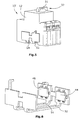
- FIGS. 1 to 4 a first embodiment of a switching device 10 according to the invention for DC applications is shown, which is constructed on the basis of a switching device for AC applications.
- the switching device 10 has a switching device housing 12 by two receiving areas 16,18,20 are arranged side by side between two opposite (outer) side walls 14, wherein in each receiving space a flow path 22 is located.
- each current path 22 comprises a movable switching contact element 24 and two mutually opposite stationary switching contact elements 26, 28, which are each provided with connection terminals 30.
- the three movable switching contact elements 24 are in common between a closed position (see Fig. 1 ) and an open position (see Fig.
- each flow path 22 has two separating sections 42, 43 which, when the movable switching contact elements 24 are open, form between their ends and the first and second stationary switching contact elements 26, 28 associated with these ends (see FIG Fig. 2 ).
- the first magnets 44 have a magnetic field with field lines in an orientation which extend transversely to the separating lines 42,43 and generate a Lorenzkraft on this separating lines 42,43 forming arcs, which drive the arcs in the direction of the first erasing devices 36 .
- the second outer magnets 46 in turn generate a magnetic field lines and an alignment, which extend transversely to the second separation lines 43 and generate a Lorenzkraft on this second separating lines 43 forming arcs, which deflect the arcs in the direction of the second erasers 38.
- the first magnets 44 are aligned with the first separation paths 42, while the second magnets 46 are arranged in extension of the adjacent second separation sections 43.
- the three-pole, originally intended for AC applications switching device 10 can now be used for DC applications, with its DC Abschalt governance compared to the DC switching capacity of an AC switching device is significantly improved, without requiring significant structural changes , Rather, it is only necessary to arrange the aforementioned magnets 44, 46 on the outside of the opposite outer sides 14 of the housing 12 of the switching device 10, wherein it should be noted that in principle a first or a second magnet, ie for all the first separating lines 42 and for all second separation lines 43 each a single magnet is required. Likewise, it should be mentioned at this point that it is not absolutely necessary for the realization of the invention to provide a switching device 10 which has two separating sections per current path.
- AC switchgear housings which have one single isolating path per current path 22, that is to have a movable switching contact element and a single fixed switching contact element per current path 22, so that then for all isolating sections only a single magnet is required.
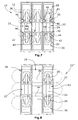
- FIGS. 5 and 6 is a comparison with the embodiment of FIGS. 1 to 4 slightly modified switching device 10 'shown, the housing 12 is constructed and constructed as it is based on the FIGS. 1 to 3 and having alternately configured outboard first and second magnets 44, 46.
- the individual components of the housing 12 according to the FIGS. 5 and 6 equal or functionally identical to the individual components of the switching device 10 of FIGS. 1 to 4 are, they are in the FIGS. 5 and 6 with the same reference numerals as in the FIGS. 1 to 4 Mistake. So is in the FIGS.
- Fig. 7 shows a plan view of the housing 12 of a modified switching device 10 "with the top removed and modification for DC applications Fig. 7 equal or functionally identical to the individual components of the switching device 10 of FIGS. 1 to 4 are, they are in Fig. 7 with the same reference numerals as in the FIGS. 1 to 4 Mistake.
- the housing 12 is according to Fig. 7 constructed as in the FIGS. 1 to 3 played.
- the housing 12 according to Fig. 7 Receiving spaces 56, which are associated with the separation sections 42,43 and are arranged on both sides of these separation sections.
- These receiving spaces 56 are used in an AC switching device of recording own magnetic field amplifying elements, as required for AC switching devices with smaller short-circuit currents to deflect the arc in the arc quenching device, where it then comes to extinguish the arc.
- the magnetic field reinforcing elements are removed, so that the receiving spaces 56 are now free to accommodate the magnets 44,46. It is possible that, unlike in Fig. 7 shown, for example, the middle current path 22 is removed, so that the switching device 10 "can be used as a two-pole DC switching device.
- the three current paths of the switching devices 10, 10 'and 10 can be connected in series (by external electrical conductors, not shown in the drawing), in order to function as a single-pole DC switching device with a total of six separating sections
- the potentially possible three current paths only two are used to implement a two-pole DC switching device
- all four current paths in Series can be switched or only two of the current paths are used as a two-pole DC switching device.
- FIG. 8 Finally, there is shown another embodiment of a DC switching device 10 "'constructed on the basis of an AC switching device housing 12. Also with respect to FIG Fig. 8 applies that those individual components of the switching device housing 12, the functionally identical or constructively equal to the elements of the switching device housing 12 of the FIGS. 1 to 3 are provided with the same reference numerals.
- the middle flow path 22 is not present, ie the middle receiving region 18 is free of a flow path 22 and in particular free of the movable switch contact element 24. Also in Fig. 8 have shown that the central receiving area 18 does not have any arc extinguishing devices. Thus, the middle receiving area 18 can now be used to receive the first and second magnets 44, 46 which are arranged in the receiving area 18 in the height of the separating lines 42 and 43 of the current paths 22 of the adjacent receiving areas 16 and 20.
Priority Applications (1)
| Application Number | Priority Date | Filing Date | Title |
|---|---|---|---|
| EP11175842A EP2383761A1 (fr) | 2007-11-17 | 2008-11-07 | Commutateur destiné à des applications à courant continu |
Applications Claiming Priority (1)
| Application Number | Priority Date | Filing Date | Title |
|---|---|---|---|
| DE102007054958A DE102007054958A1 (de) | 2007-11-17 | 2007-11-17 | Schaltgerät für Gleichstrom-Anwendungen |
Publications (2)
| Publication Number | Publication Date |
|---|---|
| EP2061053A2 true EP2061053A2 (fr) | 2009-05-20 |
| EP2061053A3 EP2061053A3 (fr) | 2010-05-12 |
Family
ID=40328454
Family Applications (2)
| Application Number | Title | Priority Date | Filing Date |
|---|---|---|---|
| EP08019482A Withdrawn EP2061053A3 (fr) | 2007-11-17 | 2008-11-07 | Commutateur destiné à des applications à courant continu |
| EP11175842A Withdrawn EP2383761A1 (fr) | 2007-11-17 | 2008-11-07 | Commutateur destiné à des applications à courant continu |
Family Applications After (1)
| Application Number | Title | Priority Date | Filing Date |
|---|---|---|---|
| EP11175842A Withdrawn EP2383761A1 (fr) | 2007-11-17 | 2008-11-07 | Commutateur destiné à des applications à courant continu |
Country Status (3)
| Country | Link |
|---|---|
| US (1) | US7915985B2 (fr) |
| EP (2) | EP2061053A3 (fr) |
| DE (1) | DE102007054958A1 (fr) |
Cited By (20)
| Publication number | Priority date | Publication date | Assignee | Title |
|---|---|---|---|---|
| WO2011147458A1 (fr) * | 2010-05-28 | 2011-12-01 | Abb Research Ltd | Commutateur pour courant continu |
| EP2393094A1 (fr) * | 2010-06-07 | 2011-12-07 | Eaton Industries GmbH | Unité de commutation dotée d'unités d'extinction d'arc |
| EP2463878A1 (fr) * | 2010-12-07 | 2012-06-13 | Eaton Industries GmbH | Commutateur doté d'une chambre d'extinction |
| EP2551867A1 (fr) * | 2011-07-28 | 2013-01-30 | Eaton Industries GmbH | Protection pour courant continu |
| EP2590192A1 (fr) | 2011-11-02 | 2013-05-08 | Eaton Industries GmbH | Commutateur pour un fonctionnement à courant continu multipolaire |
| EP2597665A1 (fr) | 2011-11-24 | 2013-05-29 | Eaton Industries GmbH | Commutateur pour courant continu doté d'au moins une chambre de commutation |
| EP2597666A1 (fr) | 2011-11-24 | 2013-05-29 | Eaton Industries GmbH | Commutateur pour courant continu doté d'au moins une chambre de commutation |
| EP2597664A1 (fr) | 2011-11-24 | 2013-05-29 | Eaton Industries GmbH | Commutateur pour courant continu doté d'au moins une chambre de commutation |
| EP2600371A1 (fr) | 2011-11-29 | 2013-06-05 | Eaton Industries GmbH | Appareil de commutation pour un fonctionnement à courant continu |
| EP2600367A1 (fr) | 2011-11-29 | 2013-06-05 | Eaton Industries GmbH | Appareil de commutation pour applications à courant continu |
| WO2013079511A1 (fr) | 2011-11-29 | 2013-06-06 | Eaton Electrical Ip Gmbh & Co. Kg | Système d'aimant permanent pour un système de commande d'arc électrique et appareil de commutation |
| EP2608234A1 (fr) | 2011-12-22 | 2013-06-26 | Eaton Industries GmbH | Disjoncteur à courant continu |
| EP2608236A1 (fr) | 2011-12-22 | 2013-06-26 | Eaton Industries GmbH | Appareil de commutation approprié au fonctionnement à courant continu |
| EP2642500A1 (fr) | 2012-03-21 | 2013-09-25 | Eaton Industries GmbH | Commutateur CC sans chambres d'extinction |
| EP2690639A1 (fr) * | 2012-07-24 | 2014-01-29 | Gorlan Team, S.L.U. | Procédé et dispositif permettant de rompre des courants électriques au moyen d'extinction d'arc |
| WO2014068053A1 (fr) * | 2012-10-31 | 2014-05-08 | Eaton Industries (Austria) Gmbh | Dispositif de commutation à courant continu |
| EP2743950A1 (fr) * | 2012-12-13 | 2014-06-18 | Eaton Electrical IP GmbH & Co. KG | Commutateur indépendant de la polarité pour la conduction et la séparation de courants continus |
| EP2747108A2 (fr) | 2012-12-20 | 2014-06-25 | Eaton Electrical IP GmbH & Co. KG | Commutateur pour un fonctionnement à courant continu |
| EP2747109A1 (fr) | 2012-12-20 | 2014-06-25 | Eaton Electrical IP GmbH & Co. KG | Commutateur |
| US9552945B2 (en) | 2012-09-27 | 2017-01-24 | Eaton Electrical Ip Gmbh & Co. Kg | Direct current switch with a device for arc extinction independent of current direction |
Families Citing this family (24)
| Publication number | Priority date | Publication date | Assignee | Title |
|---|---|---|---|---|
| PL2431989T3 (pl) * | 2010-09-20 | 2015-03-31 | Secheron Sa | Elektromechaniczny wyłącznik instalacyjny |
| EP2463876A1 (fr) * | 2010-12-07 | 2012-06-13 | Eaton Industries GmbH | Commutateur doté d'une chambre d'extinction |
| EP2463877A1 (fr) * | 2010-12-07 | 2012-06-13 | Eaton Industries GmbH | Commutateur doté d'une chambre d'extinction |
| JP5777440B2 (ja) * | 2011-08-03 | 2015-09-09 | 富士通コンポーネント株式会社 | 電磁継電器及び電磁継電器の製造方法 |
| JP5856426B2 (ja) * | 2011-10-07 | 2016-02-09 | 富士電機株式会社 | 接点装置及びこれを使用した電磁接触器 |
| US8853586B2 (en) | 2011-11-09 | 2014-10-07 | Eaton Corporation | Electrical switching apparatus including magnet assembly and first and second arc chambers |
| IN2012CH00815A (fr) | 2012-03-05 | 2015-08-21 | Gen Electric | |
| JP5966469B2 (ja) * | 2012-03-15 | 2016-08-10 | オムロン株式会社 | 封止接点装置 |
| US9343251B2 (en) * | 2013-10-30 | 2016-05-17 | Eaton Corporation | Bi-directional direct current electrical switching apparatus including small permanent magnets on ferromagnetic side members and one set of arc splitter plates |
| JP6414453B2 (ja) * | 2014-12-05 | 2018-10-31 | オムロン株式会社 | 電磁継電器 |
| WO2016088402A1 (fr) | 2014-12-05 | 2016-06-09 | オムロン株式会社 | Relais électromagnétique |
| JP2016110843A (ja) | 2014-12-05 | 2016-06-20 | オムロン株式会社 | 電磁継電器 |
| DE102015000796B4 (de) * | 2015-01-22 | 2017-03-02 | Schaltbau Gmbh | Schaltgerät mit permanentmagnetischer Lichtbogenlöschung |
| KR101943363B1 (ko) * | 2015-04-13 | 2019-04-17 | 엘에스산전 주식회사 | 전자개폐기 |
| US11239038B2 (en) | 2015-05-18 | 2022-02-01 | Gigavac, Llc | Mechanical fuse device |
| US10566160B2 (en) | 2015-05-18 | 2020-02-18 | Gigavac, Llc | Passive triggering mechanisms for use with switching devices incorporating pyrotechnic features |
| DE102017106300B4 (de) * | 2017-03-23 | 2023-07-27 | Schaltbau Gmbh | Schaltgerät mit verbesserter permanentmagnetischer Lichtbogenlöschung |
| DE102017125685A1 (de) * | 2017-11-03 | 2019-05-09 | Schaltbau Gmbh | Schaltgerät mit Lichtbogenlöscheinrichtung und Lichtbogenführung |
| DE102018204104A1 (de) * | 2018-03-16 | 2019-09-19 | Ellenberger & Poensgen Gmbh | Schalteinheit zur Trennung eines Stromkreises und Schutzschalter |
| GB2576338A (en) * | 2018-08-15 | 2020-02-19 | Eaton Intelligent Power Ltd | Switching device and method for operating a switching device |
| US11276535B2 (en) * | 2018-08-28 | 2022-03-15 | Gigavac, Llc | Passive triggering mechanisms for use with switching devices incorporating pyrotechnic features |
| FR3095890B1 (fr) * | 2019-05-06 | 2021-07-16 | Schneider Electric Ind Sas | Pôle limiteur d’interrupteur électrique et interrupteur électrique à courant continu comportant un tel pôle limiteur |
| US11443910B2 (en) | 2019-09-27 | 2022-09-13 | Gigavac, Llc | Contact levitation triggering mechanisms for use with switching devices incorporating pyrotechnic features |
| KR102349754B1 (ko) * | 2019-12-06 | 2022-01-11 | 엘에스일렉트릭(주) | 아크 박스 및 이를 포함하는 전자 접촉기 |
Citations (6)
| Publication number | Priority date | Publication date | Assignee | Title |
|---|---|---|---|---|
| EP0217106B1 (fr) | 1985-08-30 | 1991-10-16 | Licentia Patent-Verwaltungs-GmbH | Dispositif d'extinction pour disjoncteur de puissance tout courant |
| EP1594148A1 (fr) | 2004-05-05 | 2005-11-09 | ABB PATENT GmbH | Dispositif d'extinction d'arc pour disjoncteur |
| DE10352934B4 (de) | 2003-11-11 | 2005-12-22 | Siemens Ag | Lichtbogen-Löschvorrichtung |
| DE202005007878U1 (de) | 2005-05-19 | 2006-09-28 | Schaltbau Gmbh | Löschkammer |
| DE10212948B4 (de) | 2001-03-28 | 2006-11-09 | Schaltbau Gmbh | Schütz für AC- und DC-Betrieb |
| EP0980085B1 (fr) | 1998-08-13 | 2006-11-22 | Siemens Aktiengesellschaft | Disjoncteur de puissance à bobine de soufflage actionné par l'arc |
Family Cites Families (28)
| Publication number | Priority date | Publication date | Assignee | Title |
|---|---|---|---|---|
| DE340964C (de) | 1920-02-24 | 1921-09-21 | Theodor Aspe | Zigarrenspitze mit Saugrohren zum Absaugen des Rauches in der Naehe der Brennstelle |
| US2332446A (en) * | 1941-01-13 | 1943-10-19 | Allen Bradley Co | Permanent magnet blowout for electric switches |
| US2575060A (en) * | 1947-08-07 | 1951-11-13 | Allen Bradley Co | Arc interrupter for electric switches |
| US2875304A (en) * | 1956-03-30 | 1959-02-24 | Westinghouse Electric Corp | Circuit interrupter |
| DE1915972U (de) * | 1962-12-06 | 1965-05-20 | Stotz Kontakt Gmbh | Lichtbogenloeschvorrichtung mit permanentmagnet. |
| DE1874564U (de) * | 1963-04-09 | 1963-06-27 | Continental Elektro Ind Ag | Schaltkammer fuer gleichstromschaltgeraete, insbesondere gleichstromschuetze. |
| DE1884948U (de) * | 1963-10-10 | 1963-12-27 | Weyer & Zandet K G | Lichtbogenloeschvorrichtung zum fuer gleichstromschaltgeraete. |
| FR1541532A (fr) * | 1966-10-22 | 1968-10-04 | Siemens Ag | Dispositif d'extinction de l'arc électrique pour appareils de commutation à courant continu |
| DE2433536C3 (de) * | 1974-07-12 | 1980-04-17 | Schaltbau Gesellschaft Mbh, 8000 Muenchen | Elektromagnetisches Schaltgerät mit Klappanker |
| DE2448144C3 (de) * | 1974-10-09 | 1980-02-07 | Schaltbau Gesellschaft Mbh, 8000 Muenchen | Kontaktsystem fur einen um eine Achse drehbaren Klappanker |
| JPS5713628A (en) * | 1980-06-27 | 1982-01-23 | Mitsubishi Electric Corp | Direct current electromagnetic contactor |
| FR2491676A1 (fr) * | 1980-10-03 | 1982-04-09 | Thomson Csf | Relais electromagnetique |
| GB2122651B (en) | 1982-06-25 | 1985-12-04 | Atomic Energy Authority Uk | Low porosity sprayed metallic coatings |
| JPS59169010A (ja) * | 1983-03-17 | 1984-09-22 | 富士電機株式会社 | 消弧装置 |
| JP2658170B2 (ja) * | 1988-05-11 | 1997-09-30 | オムロン株式会社 | 開閉器 |
| US5004874A (en) * | 1989-11-13 | 1991-04-02 | Eaton Corporation | Direct current switching apparatus |
| US4962406A (en) * | 1989-12-26 | 1990-10-09 | Westinghouse Electric Corp. | Compact DC/AC circuit breaker with common arc extinguishing capability |
| FR2699322B1 (fr) * | 1992-12-10 | 1995-03-17 | Merlin Gerin | Disjoncteur modulaire à courant continu. |
| DE4342129A1 (de) * | 1993-12-10 | 1995-06-14 | Abb Patent Gmbh | Elektrischer Schalter |
| JP3321963B2 (ja) * | 1994-02-22 | 2002-09-09 | 株式会社デンソー | プランジャ型電磁継電器 |
| US5416455A (en) * | 1994-02-24 | 1995-05-16 | Eaton Corporation | Direct current switching apparatus |
| DE19943965A1 (de) * | 1999-09-14 | 2001-03-15 | Moeller Gmbh | Niederspannungsschaltgerät |
| CN1323410C (zh) * | 1999-10-14 | 2007-06-27 | 松下电工株式会社 | 接点装置 |
| JP2004311389A (ja) * | 2003-02-21 | 2004-11-04 | Sumitomo Electric Ind Ltd | 直流リレー |
| JP2005026182A (ja) * | 2003-07-02 | 2005-01-27 | Matsushita Electric Works Ltd | 電磁開閉装置 |
| DE102005007282A1 (de) * | 2005-02-17 | 2006-08-24 | Abb Patent Gmbh | Elektrisches Installationsgerät mit Lichtbogen-Vorkammerraum, Vorkammerplatten und strombegrenzender Lichtbogenlöscheinrichtung |
| JP2007324038A (ja) * | 2006-06-02 | 2007-12-13 | Mitsubishi Electric Corp | 回路遮断器 |
| DE102006035844B4 (de) * | 2006-08-01 | 2008-06-19 | Schaltbau Gmbh | Schütz für Gleichstrom- und Wechselstrombetrieb |
-
2007
- 2007-11-17 DE DE102007054958A patent/DE102007054958A1/de not_active Ceased
-
2008
- 2008-11-07 EP EP08019482A patent/EP2061053A3/fr not_active Withdrawn
- 2008-11-07 EP EP11175842A patent/EP2383761A1/fr not_active Withdrawn
- 2008-11-14 US US12/271,562 patent/US7915985B2/en active Active
Patent Citations (6)
| Publication number | Priority date | Publication date | Assignee | Title |
|---|---|---|---|---|
| EP0217106B1 (fr) | 1985-08-30 | 1991-10-16 | Licentia Patent-Verwaltungs-GmbH | Dispositif d'extinction pour disjoncteur de puissance tout courant |
| EP0980085B1 (fr) | 1998-08-13 | 2006-11-22 | Siemens Aktiengesellschaft | Disjoncteur de puissance à bobine de soufflage actionné par l'arc |
| DE10212948B4 (de) | 2001-03-28 | 2006-11-09 | Schaltbau Gmbh | Schütz für AC- und DC-Betrieb |
| DE10352934B4 (de) | 2003-11-11 | 2005-12-22 | Siemens Ag | Lichtbogen-Löschvorrichtung |
| EP1594148A1 (fr) | 2004-05-05 | 2005-11-09 | ABB PATENT GmbH | Dispositif d'extinction d'arc pour disjoncteur |
| DE202005007878U1 (de) | 2005-05-19 | 2006-09-28 | Schaltbau Gmbh | Löschkammer |
Cited By (46)
| Publication number | Priority date | Publication date | Assignee | Title |
|---|---|---|---|---|
| WO2011147458A1 (fr) * | 2010-05-28 | 2011-12-01 | Abb Research Ltd | Commutateur pour courant continu |
| US8502102B2 (en) | 2010-05-28 | 2013-08-06 | Abb Research Ltd. | DC switching device |
| RU2561716C2 (ru) * | 2010-06-07 | 2015-09-10 | ИТОН ЭЛЕКТРИКАЛ АйПи ГМБХ УНД КО. КГ | Блок переключения с блоками гашения дуги |
| EP2393094A1 (fr) * | 2010-06-07 | 2011-12-07 | Eaton Industries GmbH | Unité de commutation dotée d'unités d'extinction d'arc |
| WO2011154380A1 (fr) | 2010-06-07 | 2011-12-15 | Eaton Industries Gmbh | Unité de commutation munie d'unités d'extinction d'arc |
| US8921728B2 (en) | 2010-06-07 | 2014-12-30 | Eaton Electrical Ip Gmbh & Co. Kg | Switch unit with arc-extinguishing units |
| EP2463878A1 (fr) * | 2010-12-07 | 2012-06-13 | Eaton Industries GmbH | Commutateur doté d'une chambre d'extinction |
| WO2012076606A1 (fr) * | 2010-12-07 | 2012-06-14 | Eaton Industries Gmbh | Interrupteur à chambre d'extinction |
| RU2581599C2 (ru) * | 2010-12-07 | 2016-04-20 | ИТОН ЭЛЕКТРИКАЛ АйПи ГМБХ УНД КО. КГ | Выключатель с дугогасительной камерой |
| US9208977B2 (en) | 2010-12-07 | 2015-12-08 | Eaton Electrical Ip Gmbh & Co. Kg | Switch having a quenching chamber |
| WO2013014281A1 (fr) * | 2011-07-28 | 2013-01-31 | Eaton Electrical Ip Gmbh & Co. Kg | Protection pour fonctionnement en courant continu |
| US8937519B2 (en) | 2011-07-28 | 2015-01-20 | Eaton Electrical Ip Gmbh & Co. Kg | Contactor for DC operation |
| EP2551867A1 (fr) * | 2011-07-28 | 2013-01-30 | Eaton Industries GmbH | Protection pour courant continu |
| WO2013064629A1 (fr) | 2011-11-02 | 2013-05-10 | Eaton Electrical Ip Gmbh & Co. Kg | Commutateur pour fonctionnement en courant continu multipolaire |
| EP2590192A1 (fr) | 2011-11-02 | 2013-05-08 | Eaton Industries GmbH | Commutateur pour un fonctionnement à courant continu multipolaire |
| WO2013076303A1 (fr) | 2011-11-24 | 2013-05-30 | Eaton Electrical Ip Gmbh & Co. Kg | Commutateur pour fonctionnement en courant continu comportant au moins une chambre de commutation |
| WO2013076310A1 (fr) | 2011-11-24 | 2013-05-30 | Eaton Electrical Ip Gmbh & Co. Kg | Commutateur pour fonctionnement en courant continu comportant au moins une chambre de commutation |
| EP2597665A1 (fr) | 2011-11-24 | 2013-05-29 | Eaton Industries GmbH | Commutateur pour courant continu doté d'au moins une chambre de commutation |
| EP2597666A1 (fr) | 2011-11-24 | 2013-05-29 | Eaton Industries GmbH | Commutateur pour courant continu doté d'au moins une chambre de commutation |
| EP2597664A1 (fr) | 2011-11-24 | 2013-05-29 | Eaton Industries GmbH | Commutateur pour courant continu doté d'au moins une chambre de commutation |
| WO2013076299A1 (fr) | 2011-11-24 | 2013-05-30 | Eaton Electrical Ip Gmbh & Co. Kg | Commutateur pour fonctionnement en courant continu comportant au moins une chambre de commutation |
| EP2600371A1 (fr) | 2011-11-29 | 2013-06-05 | Eaton Industries GmbH | Appareil de commutation pour un fonctionnement à courant continu |
| EP2600367A1 (fr) | 2011-11-29 | 2013-06-05 | Eaton Industries GmbH | Appareil de commutation pour applications à courant continu |
| US9552944B2 (en) | 2011-11-29 | 2017-01-24 | Eaton Electrical Ip Gmbh & Co. Kg | Switching device for direct current applications |
| US10290439B2 (en) | 2011-11-29 | 2019-05-14 | Eaton Intelligent Power Limited | Permanent magnet assembly for an arc driver assembly and switching device |
| EP2631928A1 (fr) | 2011-11-29 | 2013-08-28 | Eaton Industries GmbH | Système d'aimant permanent pour un circuit d'attaque à arc lumineux et appareil de commutation |
| WO2013079511A1 (fr) | 2011-11-29 | 2013-06-06 | Eaton Electrical Ip Gmbh & Co. Kg | Système d'aimant permanent pour un système de commande d'arc électrique et appareil de commutation |
| WO2013079508A1 (fr) | 2011-11-29 | 2013-06-06 | Eaton Electrical Ip Gmbh & Co. Kg | Appareil de commutation convenant à un fonctionnement en courant continu |
| WO2013079269A1 (fr) | 2011-11-29 | 2013-06-06 | Eaton Electrical Ip Gmbh & Co. Kg | Appareil de coupure pour applications à courant continu |
| WO2013092351A1 (fr) | 2011-12-22 | 2013-06-27 | Eaton Electrical Ip Gmbh & Co. Kg | Appareil de coupure convenant pour un fonctionnement en courant continu |
| EP2608234A1 (fr) | 2011-12-22 | 2013-06-26 | Eaton Industries GmbH | Disjoncteur à courant continu |
| US9552943B2 (en) | 2011-12-22 | 2017-01-24 | Eaton Electrical Ip Gmbh & Co. Kg | Switching device which is suitable for DC operation |
| EP2608236A1 (fr) | 2011-12-22 | 2013-06-26 | Eaton Industries GmbH | Appareil de commutation approprié au fonctionnement à courant continu |
| WO2013092348A1 (fr) | 2011-12-22 | 2013-06-27 | Eaton Electrical Ip Gmbh & Co. Kg | Commutateur convenant pour un fonctionnement en courant continu |
| WO2013139870A1 (fr) | 2012-03-21 | 2013-09-26 | Eaton Electrical Ip Gmbh & Co. Kg | Commutateur cc sans chambres d'extinction d'arc |
| EP2642500A1 (fr) | 2012-03-21 | 2013-09-25 | Eaton Industries GmbH | Commutateur CC sans chambres d'extinction |
| EP2690639A1 (fr) * | 2012-07-24 | 2014-01-29 | Gorlan Team, S.L.U. | Procédé et dispositif permettant de rompre des courants électriques au moyen d'extinction d'arc |
| US9552945B2 (en) | 2012-09-27 | 2017-01-24 | Eaton Electrical Ip Gmbh & Co. Kg | Direct current switch with a device for arc extinction independent of current direction |
| WO2014068053A1 (fr) * | 2012-10-31 | 2014-05-08 | Eaton Industries (Austria) Gmbh | Dispositif de commutation à courant continu |
| RU2656231C2 (ru) * | 2012-10-31 | 2018-06-04 | Итон Индастриз (Острия) Гмбх | Коммутационный аппарат постоянного тока |
| EP2743950A1 (fr) * | 2012-12-13 | 2014-06-18 | Eaton Electrical IP GmbH & Co. KG | Commutateur indépendant de la polarité pour la conduction et la séparation de courants continus |
| US9129761B2 (en) | 2012-12-20 | 2015-09-08 | Eaton Electrical Ip Gmbh & Co. Kg | Switching device suitable for direct current operation |
| US9418804B2 (en) | 2012-12-20 | 2016-08-16 | Eaton Electrical Ip Gmbh & Co. Kg | Switching device |
| DE102013111953A1 (de) | 2012-12-20 | 2014-06-26 | Eaton Electrical Ip Gmbh & Co. Kg | Schaltgerät |
| EP2747109A1 (fr) | 2012-12-20 | 2014-06-25 | Eaton Electrical IP GmbH & Co. KG | Commutateur |
| EP2747108A2 (fr) | 2012-12-20 | 2014-06-25 | Eaton Electrical IP GmbH & Co. KG | Commutateur pour un fonctionnement à courant continu |
Also Published As
| Publication number | Publication date |
|---|---|
| EP2383761A1 (fr) | 2011-11-02 |
| US20090127229A1 (en) | 2009-05-21 |
| DE102007054958A1 (de) | 2009-06-04 |
| EP2061053A3 (fr) | 2010-05-12 |
| US7915985B2 (en) | 2011-03-29 |
Similar Documents
| Publication | Publication Date | Title |
|---|---|---|
| EP2061053A2 (fr) | Commutateur destiné à des applications à courant continu | |
| EP1313117B1 (fr) | Dispositif d'extinction d'arc pour un interrupteur électronique | |
| EP2786385B1 (fr) | Appareil de commutation pour applications à courant continu | |
| EP2774158B1 (fr) | Commutateur pour un fonctionnement à courant continu multipolaire | |
| DE102011089234B4 (de) | Lichtbogen-Löschvorrichtung und Schutzschaltgerät | |
| WO2012010227A1 (fr) | Contacteur pour cc à commutation unidirectionnelle | |
| EP2783378B1 (fr) | Ensemble COMMUTATEUR POUR COURANT CONTINU DOTÉ D'AU MOINS UNE CHAMBRE DE COMMUTATION | |
| EP2783379B1 (fr) | Commutateur pour courant continu doté d'au moins une chambre de commutation | |
| DE102007054960B3 (de) | Schaltgerät für Gleichstrom-Anwendungen | |
| EP3428942B1 (fr) | Dispositif d'extinction d'arc de courant continu et appareil de commutation de courant continu électromécanique | |
| EP0350825B1 (fr) | Appareil de commutation électrique | |
| EP2795643B1 (fr) | Disjonteur à courant continu | |
| EP0251160B1 (fr) | Dispositif d'extinction pour disjoncteurs électriques | |
| EP2030211A1 (fr) | Dispositif de commutation de puissance ou disjoncteur de protection | |
| DE3337562A1 (de) | Loescheinrichtung fuer einen leitungsschutzschalter | |
| EP0358287B1 (fr) | Elément-moteur pour un disjoncteur électrique multipolaire de puissance basse tension | |
| DE1232644B (de) | Schaltgeraet mit einer eine Loeschblechanordnung enthaltenden Lichtbogenkammer | |
| DE3443122A1 (de) | Vorrichtung zur unterbrechung von stromkreisen | |
| DE19525286C2 (de) | Mehrpoliger Vakuumschalter mit einer Antriebsvorrichtung | |
| DE1908152B2 (de) | Funkenstreckenanordnung für einen Überspannungsableiter | |
| EP0227585B1 (fr) | Dispositif de sectionnement pour appareils interrupteurs montés d'une façon déplaçable sur glissières | |
| DE3810977C2 (de) | Strombegrenzende Schalteinrichtung mit elektrodynamisch öffnenden Schaltstücken | |
| DE2942088C2 (de) | Elektrisches Installationsgerät | |
| DE10244635A1 (de) | Leistungsschalter | |
| EP1220260A1 (fr) | Disjoncteur à système de contacts à coupure double |
Legal Events
| Date | Code | Title | Description |
|---|---|---|---|
| PUAI | Public reference made under article 153(3) epc to a published international application that has entered the european phase |
Free format text: ORIGINAL CODE: 0009012 |
|
| AK | Designated contracting states |
Kind code of ref document: A2 Designated state(s): AT BE BG CH CY CZ DE DK EE ES FI FR GB GR HR HU IE IS IT LI LT LU LV MC MT NL NO PL PT RO SE SI SK TR |
|
| AX | Request for extension of the european patent |
Extension state: AL BA MK RS |
|
| PUAL | Search report despatched |
Free format text: ORIGINAL CODE: 0009013 |
|
| RAP1 | Party data changed (applicant data changed or rights of an application transferred) |
Owner name: EATON INDUSTIES GMBH |
|
| AK | Designated contracting states |
Kind code of ref document: A3 Designated state(s): AT BE BG CH CY CZ DE DK EE ES FI FR GB GR HR HU IE IS IT LI LT LU LV MC MT NL NO PL PT RO SE SI SK TR |
|
| AX | Request for extension of the european patent |
Extension state: AL BA MK RS |
|
| RAP1 | Party data changed (applicant data changed or rights of an application transferred) |
Owner name: EATON INDUSTRIES GMBH |
|
| 17P | Request for examination filed |
Effective date: 20101112 |
|
| 17Q | First examination report despatched |
Effective date: 20101220 |
|
| AKX | Designation fees paid |
Designated state(s): AT BE BG CH CY CZ DE DK EE ES FI FR GB GR HR HU IE IS IT LI LT LU LV MC MT NL NO PL PT RO SE SI SK TR |
|
| STAA | Information on the status of an ep patent application or granted ep patent |
Free format text: STATUS: THE APPLICATION IS DEEMED TO BE WITHDRAWN |
|
| 18D | Application deemed to be withdrawn |
Effective date: 20130604 |