EP1220260A1 - Disjoncteur à système de contacts à coupure double - Google Patents
Disjoncteur à système de contacts à coupure double Download PDFInfo
- Publication number
- EP1220260A1 EP1220260A1 EP00811248A EP00811248A EP1220260A1 EP 1220260 A1 EP1220260 A1 EP 1220260A1 EP 00811248 A EP00811248 A EP 00811248A EP 00811248 A EP00811248 A EP 00811248A EP 1220260 A1 EP1220260 A1 EP 1220260A1
- Authority
- EP
- European Patent Office
- Prior art keywords
- contact
- circuit breaker
- current
- conductor section
- current sensor
- Prior art date
- Legal status (The legal status is an assumption and is not a legal conclusion. Google has not performed a legal analysis and makes no representation as to the accuracy of the status listed.)
- Withdrawn
Links
Images


Classifications
-
- H—ELECTRICITY
- H01—ELECTRIC ELEMENTS
- H01H—ELECTRIC SWITCHES; RELAYS; SELECTORS; EMERGENCY PROTECTIVE DEVICES
- H01H71/00—Details of the protective switches or relays covered by groups H01H73/00 - H01H83/00
- H01H71/10—Operating or release mechanisms
- H01H71/12—Automatic release mechanisms with or without manual release
- H01H71/121—Protection of release mechanisms
-
- H—ELECTRICITY
- H01—ELECTRIC ELEMENTS
- H01H—ELECTRIC SWITCHES; RELAYS; SELECTORS; EMERGENCY PROTECTIVE DEVICES
- H01H73/00—Protective overload circuit-breaking switches in which excess current opens the contacts by automatic release of mechanical energy stored by previous operation of a hand reset mechanism
- H01H73/02—Details
- H01H73/18—Means for extinguishing or suppressing arc
Definitions
- the invention is based on a circuit breaker according to the Preamble of claim 1.
- a circuit breaker according to the Preamble of claim 1.
- Such a switch can be used as Miniature circuit breakers are used in low-voltage distributors and is characterized by a large breaking capacity and small dimensions by a quick response.
- a switch of the aforementioned type is for example in CH 543 174 A as well described in EP 619 592 A.
- the switch described has a cuboid housing, in which, in addition to a double-break Contact arrangement also two connection terminals and a trigger mechanism are accommodated with a drive and a trigger.
- the contact arrangement contains two side-by-side contact systems, which in series in a current path running between the two connection terminals of the switch are switched.
- the contact systems each contain one fixed and a movable contact piece.
- the moving contact pieces are attached to a bridge contact carrier. Form when switching off therefore two switching arcs through which the cut-off current flows, which repel each other. Do not run the two arcs with the same speed, so the slower arc from the faster repelled moving arc and is possibly prevented from the arc extinguisher favoring the arc extinguishing.
- the object of the invention is as set out in the claims based on the circuit breaker of the type mentioned in such a way to further develop that it is also large while maintaining its dimensions It can switch off short-circuit currents with great certainty.
- circuit breaker according to the invention is in the current path between the Power connections provided an intermediate conductor section, which a movable contact piece of a first two contact systems and a fixed contact piece of the second two contact systems electrically conductive connects with each other.
- This ensures that when switching off the in the switching arcs formed in the same direction from both contact systems Cut-off current can be flowed through.
- the two switching arcs collide therefore no longer take off, but attract each other.
- a shift the switching arcs relative to each other is avoided.
- the two arcs now run into arc quenching chambers with great certainty and are deleted there practically at the same time.
- the circuit breaker after the The invention is therefore characterized by a high breaking capacity.
- the intermediate conductor section angled.
- the one Leg of the angle can then be rigid with a contact carrier fixed contact piece or alternatively via a flexible one Conductor section with a contact carrier of a movable contact piece of the contact systems are connected while the other leg of the angle is connected to a current sensor.
- the current sensor as a bimetal strip formed, so the one end of the bimetallic strip with the leg end connected and the bimetal strip parallel in a particularly space-saving manner be arranged to the leg.
- the switch according to the invention has two on the two contact pieces each Contact system connecting and with the arc quenching chamber co-operating arc tracks, so one on short circuit and / or Overcurrent responsive current sensor of the switch during a Switching off the effect of the cutoff current are withdrawn if this current sensor is connected in parallel to a isolating section which is separated from the is formed.
- Contains the switch after the Invention two current sensors, one of which is overcurrent and the other responsive to short-circuit current, both can affect the effect of the cut-off current withdrawn during the switch-off phase, if parallel to the isolating section a series connection of both current sensors is laid.
- the switch according to the has an improved current-limiting effect Invention then when the current sensor in series to the isolating path in the Current path is switched.
- the impedance of the current sensor which is preferably is designed as a bimetallic element, is then in series with the switching arcs and then relieves the switching arcs when limiting the current.
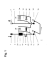
- the equivalent circuits shown in FIGS. 1 to 6 each contain one current path 7 between two power connections 1, 2 Circuit breaker. In all equivalent circuits, this current path has in each case a current conductor section 3 or 2 connected to the power connection 1 or 2 4 on.
- the equivalent circuits according to Figures 1, 2 and 4 is the Current conductor section 3 each with a short-circuit current release 5, for example with a coil of an impact anchor or with another Magnetic release, connected.
- the short-circuit current release 5 is not part of one Tripping device shown for actuating a two contact systems 10, 15th containing contact arrangement of the switch.
- the short-circuit current release 5 is in turn via an overcurrent release 6, which as a bimetal or other thermal Trigger can be executed and also part of the not shown Tripping device is, with a fixed contact 11 of the contact system 10 connected.
- an overcurrent release 6 which as a bimetal or other thermal Trigger can be executed and also part of the not shown Tripping device is, with a fixed contact 11 of the contact system 10 connected.
- a fixed contact 14 of the contact system 15 is with the Current conductor 4 connected.
- the Short-circuit current release 5 each directly with the fixed contact 11 of the contact system 10 connected.
- the movable contact 12 of the Contact system 10 is each one of a flexible design Current conductor section 25, for example a stranded wire, with the overcurrent release 6 connected, which in turn each with an intermediate conductor section 26 the fixed contact 14 of the contact system 15 is connected.
- the Movable contact 13 of the contact system 15 is flexible in each case trained current conductor section 27, for example a strand, to the Current conductor section 4 connected.
- the current conductor section 3 each via the overcurrent release 6 and the flexibly trained Current conductor section 25 with the movable contact 12 of the contact system 10 connected.
- the fixed contact 11 of the contact system 10 is over the Short-circuit current release 5 connected to the intermediate conductor section 26, which in turn via the flexible conductor section 27 to the movable contact 13 of the contact system 15 is connected.
- the Fixed contact 14 of the contact system 15 is on the current conductor section 4 connected.
- the current conductor section 3 is above the Overcurrent release 6 with the fixed contact 11 of the contact system 10 connected.
- the movable contact 12 of this contact system is over the flexible conductor section 25 and the intermediate conductor section 26 with the fixed contact 14 of the contact system 15 connected.
- the mobile Contact 13 of this contact system is about the more flexible one Current conductor section 27 and the short-circuit current release 5 to the Current conductor section 4 connected.
- the arc runner 17 or 18 is also included a non-designated contact carrier of the fixed contact 11 or 14 connected.
- the arc rail 19 is with the Connection point of overcurrent release 6 and intermediate conductor section 26 and the arc runner 20 is connected to the current conductor section 4.
- the equivalent circuit according to Fig. 3 is the arc runner 19 with the current conductor section 3 and the arc runner 20 with the Connection point of intermediate conductor section 26 and flexibly designed Current conductor section 27 connected.
- both equivalent circuits are common that the overcurrent release 6 each parallel to one of the Arc guide rails 17 and 19 formed by the arc 21 bridged separation distance.
- the current to be switched off flows as if by arrows specified - from the power connection 1 via the conductor section 3, the Short-circuit current release 5, the overcurrent release 6, the contact systems 10 and 15 and the current conductor section 4 to the power connection 2.
- the arcs are in opposite directions from the one to be switched off Current flowed through. Since the arcing chambers of both contact systems 10 and 15 are laterally adjacent, the arcs collide due to electrodynamic forces.
- Switches according to the invention are those formed when switching off and commutating on the arc rails 17, 19 and 18, 20 Arcs 21 and 22 flow in the same direction from the current to be switched off.
- this is not achieved in that the movable contacts 12 and 13 of the two contact systems 10 and 15 arranged on a contact bridge but because the movable contact 12 of the contact system 10 with the fixed contact 14 of the contact system 15 electrically conductive connected is.
- a corresponding connection can alternatively also between the movable contact 13 and the fixed contact 11 exist. In each In this case, this connection has the one shown in FIGS. 2 to 6 Intermediate conductor section 26.
- this intermediate conductor section 26 is mainly in the Arranged middle between the two contact systems 10, 15. He is angled executed. Not at the free end of one for reasons of clarity designated leg of the angle is a perpendicular to the angle Molded contact carrier for the fixed contact 14. The down led other leg of the angle carries the at its lower end Overcurrent release 6 designed as a bimetal strip. This bimetal strip is out in a space-saving manner parallel to the aforementioned leg and at its upper end with the stranded wire, i.e. H. flexible, educated Current conductor section 25 connected.
- the Intermediate conductor section 26 is also formed in the switch according to FIG. 4 and arranged.
- one leg of the angle can also via the flexible current conductor section 27 with the movable Contact 13 and the other leg over the coil of the Short-circuit current release 5 to be connected to the fixed contact 11.
- This design is provided for the switches according to FIGS. 3 and 5.
- a particularly advantageous embodiment of the manufacturing technology Current path is provided for the switch according to Fig. 6.
- the overcurrent release 5 parallel to that of the two Arc runner, 17, 19 formed and when switching off the arc 21 bridged isolating path is preferably connected as Bimetal element trained overcurrent release 6 only briefly the effect of exposed to current to be switched off.
- the overcurrent release 6 can therefore be relatively weak.
- the impedance of the overcurrent release 6 is added to the Impedances of the arcs 21, 22 and then supports them in the Current limit.
- the switching capacity of the circuit breaker is additional increased.
Priority Applications (5)
| Application Number | Priority Date | Filing Date | Title |
|---|---|---|---|
| EP00811248A EP1220260A1 (fr) | 2000-12-27 | 2000-12-27 | Disjoncteur à système de contacts à coupure double |
| PCT/CH2001/000735 WO2002052598A1 (fr) | 2000-12-27 | 2001-12-20 | Disjoncteur dote d'un dispositif de contact a interruption double |
| EP01271945A EP1346388A1 (fr) | 2000-12-27 | 2001-12-20 | Disjoncteur dote d'un dispositif de contact a interruption double |
| US10/203,904 US20030117246A1 (en) | 2000-12-27 | 2001-12-20 | Power switch with a double breaking contact arrangement |
| CA002400387A CA2400387A1 (fr) | 2000-12-27 | 2001-12-20 | Disjoncteur dote d'un dispositif de contact a interruption double |
Applications Claiming Priority (1)
| Application Number | Priority Date | Filing Date | Title |
|---|---|---|---|
| EP00811248A EP1220260A1 (fr) | 2000-12-27 | 2000-12-27 | Disjoncteur à système de contacts à coupure double |
Publications (1)
| Publication Number | Publication Date |
|---|---|
| EP1220260A1 true EP1220260A1 (fr) | 2002-07-03 |
Family
ID=8175111
Family Applications (2)
| Application Number | Title | Priority Date | Filing Date |
|---|---|---|---|
| EP00811248A Withdrawn EP1220260A1 (fr) | 2000-12-27 | 2000-12-27 | Disjoncteur à système de contacts à coupure double |
| EP01271945A Withdrawn EP1346388A1 (fr) | 2000-12-27 | 2001-12-20 | Disjoncteur dote d'un dispositif de contact a interruption double |
Family Applications After (1)
| Application Number | Title | Priority Date | Filing Date |
|---|---|---|---|
| EP01271945A Withdrawn EP1346388A1 (fr) | 2000-12-27 | 2001-12-20 | Disjoncteur dote d'un dispositif de contact a interruption double |
Country Status (4)
| Country | Link |
|---|---|
| US (1) | US20030117246A1 (fr) |
| EP (2) | EP1220260A1 (fr) |
| CA (1) | CA2400387A1 (fr) |
| WO (1) | WO2002052598A1 (fr) |
Cited By (1)
| Publication number | Priority date | Publication date | Assignee | Title |
|---|---|---|---|---|
| WO2003001549A1 (fr) * | 2001-06-22 | 2003-01-03 | Abb Service S.R.L. | Pôle de disjoncteur miniature |
Families Citing this family (1)
| Publication number | Priority date | Publication date | Assignee | Title |
|---|---|---|---|---|
| AU2002950581A0 (en) * | 2002-08-02 | 2002-09-12 | Wayne Callen | Electrical safety circuit |
Citations (4)
| Publication number | Priority date | Publication date | Assignee | Title |
|---|---|---|---|---|
| CH543174A (de) * | 1971-09-30 | 1973-10-15 | Carl Maier & Cie Elek Sche Sch | Leitungsschutzschalter |
| EP0418754A2 (fr) * | 1989-09-18 | 1991-03-27 | Mitsubishi Denki Kabushiki Kaisha | Appareil de limitation de courant |
| EP0619592A1 (fr) * | 1993-04-07 | 1994-10-12 | Schneider Electric Sa | Disjoncteur électrique à répulsion électrodynamique des contacts et à chambres de coupure double |
| EP0649155A1 (fr) * | 1993-10-15 | 1995-04-19 | Hager Electro S.A. | Tôle de conduction double pour chambre de conduction d'arc de disjoncteur |
Family Cites Families (2)
| Publication number | Priority date | Publication date | Assignee | Title |
|---|---|---|---|---|
| JPH10285037A (ja) * | 1997-04-10 | 1998-10-23 | Mitsubishi Electric Corp | アナログ−デジタル変換回路 |
| US5874873A (en) * | 1997-08-22 | 1999-02-23 | Eaton Corporation | Electric control apparatus |
-
2000
- 2000-12-27 EP EP00811248A patent/EP1220260A1/fr not_active Withdrawn
-
2001
- 2001-12-20 WO PCT/CH2001/000735 patent/WO2002052598A1/fr not_active Application Discontinuation
- 2001-12-20 US US10/203,904 patent/US20030117246A1/en not_active Abandoned
- 2001-12-20 EP EP01271945A patent/EP1346388A1/fr not_active Withdrawn
- 2001-12-20 CA CA002400387A patent/CA2400387A1/fr not_active Abandoned
Patent Citations (4)
| Publication number | Priority date | Publication date | Assignee | Title |
|---|---|---|---|---|
| CH543174A (de) * | 1971-09-30 | 1973-10-15 | Carl Maier & Cie Elek Sche Sch | Leitungsschutzschalter |
| EP0418754A2 (fr) * | 1989-09-18 | 1991-03-27 | Mitsubishi Denki Kabushiki Kaisha | Appareil de limitation de courant |
| EP0619592A1 (fr) * | 1993-04-07 | 1994-10-12 | Schneider Electric Sa | Disjoncteur électrique à répulsion électrodynamique des contacts et à chambres de coupure double |
| EP0649155A1 (fr) * | 1993-10-15 | 1995-04-19 | Hager Electro S.A. | Tôle de conduction double pour chambre de conduction d'arc de disjoncteur |
Cited By (1)
| Publication number | Priority date | Publication date | Assignee | Title |
|---|---|---|---|---|
| WO2003001549A1 (fr) * | 2001-06-22 | 2003-01-03 | Abb Service S.R.L. | Pôle de disjoncteur miniature |
Also Published As
| Publication number | Publication date |
|---|---|
| US20030117246A1 (en) | 2003-06-26 |
| CA2400387A1 (fr) | 2002-07-04 |
| WO2002052598A1 (fr) | 2002-07-04 |
| EP1346388A1 (fr) | 2003-09-24 |
Similar Documents
| Publication | Publication Date | Title |
|---|---|---|
| EP2383761A1 (fr) | Commutateur destiné à des applications à courant continu | |
| WO2012076606A1 (fr) | Interrupteur à chambre d'extinction | |
| DE112007003283T5 (de) | Doppelunterbrechungskontaktsystem für einen Niederspannungsleistungsschalter und das Doppelunterbrechungskontaktsystem umfassender Kompaktleistungsschalter | |
| EP0150486B1 (fr) | Interrupteur de circuit électrique | |
| EP1683173B1 (fr) | Dispositif d'extinction d'arc | |
| EP1735803B1 (fr) | Dispositif de commutation | |
| EP0350825B1 (fr) | Appareil de commutation électrique | |
| EP3428942B1 (fr) | Dispositif d'extinction d'arc de courant continu et appareil de commutation de courant continu électromécanique | |
| DE4335965A1 (de) | Motorstarter mit integriertem Kurzschlußschutz | |
| EP2030211A1 (fr) | Dispositif de commutation de puissance ou disjoncteur de protection | |
| DE10291133B4 (de) | Gehäuse für ein Schaltgerät | |
| DE19903837B4 (de) | Selbsterholende Strombegrenzungseinrichtung mit Flüssigmetall | |
| US4562320A (en) | Current-limiting device | |
| EP1220260A1 (fr) | Disjoncteur à système de contacts à coupure double | |
| DE2234423A1 (de) | Installationsselbstschalter in schalenbauweise | |
| EP2393096B1 (fr) | Appareil de commutation basse tension pouvant être interrompu facilement, notamment commutateur de protection de ligne | |
| EP2541574B1 (fr) | Disjoncteur électrique à double point de rupture | |
| DE2751452C2 (de) | Elektrisches Schaltgerät | |
| EP3889986B1 (fr) | Disjoncteur de protection compact électromécanique | |
| DE2826243A1 (de) | Elektrisches schaltgeraet | |
| EP1615246A1 (fr) | Dispositif d'extinction d'arc pour un disjoncteur | |
| AT402583B (de) | Leitungsschutzschalter mit einem thermisch und magnetisch geschützten aussenleiterpol und einem ungeschützten nulleiterpol | |
| DE3034189C2 (de) | Zweipoliger Niederspannungsschutzschalter mit Einfachunterbrechung und elektrodynamischer Kompensation der Kontaktöffnungskräfte | |
| DE19734676A1 (de) | Schaltgerät | |
| DE102020210028A1 (de) | Bedienerunabhängiges Kompaktsprungschaltwerk und elektromechanisches Schutzschaltgerät |
Legal Events
| Date | Code | Title | Description |
|---|---|---|---|
| PUAI | Public reference made under article 153(3) epc to a published international application that has entered the european phase |
Free format text: ORIGINAL CODE: 0009012 |
|
| AK | Designated contracting states |
Kind code of ref document: A1 Designated state(s): AT BE CH CY DE DK ES FI FR GB GR IE IT LI LU MC NL PT SE TR |
|
| AX | Request for extension of the european patent |
Free format text: AL;LT;LV;MK;RO;SI |
|
| AKX | Designation fees paid | ||
| REG | Reference to a national code |
Ref country code: DE Ref legal event code: 8566 |
|
| STAA | Information on the status of an ep patent application or granted ep patent |
Free format text: STATUS: THE APPLICATION IS DEEMED TO BE WITHDRAWN |
|
| 18D | Application deemed to be withdrawn |
Effective date: 20030104 |