EP1220260A1 - Circuit breaker with a double break contact arrangement - Google Patents
Circuit breaker with a double break contact arrangement Download PDFInfo
- Publication number
- EP1220260A1 EP1220260A1 EP00811248A EP00811248A EP1220260A1 EP 1220260 A1 EP1220260 A1 EP 1220260A1 EP 00811248 A EP00811248 A EP 00811248A EP 00811248 A EP00811248 A EP 00811248A EP 1220260 A1 EP1220260 A1 EP 1220260A1
- Authority
- EP
- European Patent Office
- Prior art keywords
- contact
- circuit breaker
- current
- conductor section
- current sensor
- Prior art date
- Legal status (The legal status is an assumption and is not a legal conclusion. Google has not performed a legal analysis and makes no representation as to the accuracy of the status listed.)
- Withdrawn
Links
Images


Classifications
-
- H—ELECTRICITY
- H01—ELECTRIC ELEMENTS
- H01H—ELECTRIC SWITCHES; RELAYS; SELECTORS; EMERGENCY PROTECTIVE DEVICES
- H01H71/00—Details of the protective switches or relays covered by groups H01H73/00 - H01H83/00
- H01H71/10—Operating or release mechanisms
- H01H71/12—Automatic release mechanisms with or without manual release
- H01H71/121—Protection of release mechanisms
-
- H—ELECTRICITY
- H01—ELECTRIC ELEMENTS
- H01H—ELECTRIC SWITCHES; RELAYS; SELECTORS; EMERGENCY PROTECTIVE DEVICES
- H01H73/00—Protective overload circuit-breaking switches in which excess current opens the contacts by automatic release of mechanical energy stored by previous operation of a hand reset mechanism
- H01H73/02—Details
- H01H73/18—Means for extinguishing or suppressing arc
Definitions
- the invention is based on a circuit breaker according to the Preamble of claim 1.
- a circuit breaker according to the Preamble of claim 1.
- Such a switch can be used as Miniature circuit breakers are used in low-voltage distributors and is characterized by a large breaking capacity and small dimensions by a quick response.
- a switch of the aforementioned type is for example in CH 543 174 A as well described in EP 619 592 A.
- the switch described has a cuboid housing, in which, in addition to a double-break Contact arrangement also two connection terminals and a trigger mechanism are accommodated with a drive and a trigger.
- the contact arrangement contains two side-by-side contact systems, which in series in a current path running between the two connection terminals of the switch are switched.
- the contact systems each contain one fixed and a movable contact piece.
- the moving contact pieces are attached to a bridge contact carrier. Form when switching off therefore two switching arcs through which the cut-off current flows, which repel each other. Do not run the two arcs with the same speed, so the slower arc from the faster repelled moving arc and is possibly prevented from the arc extinguisher favoring the arc extinguishing.
- the object of the invention is as set out in the claims based on the circuit breaker of the type mentioned in such a way to further develop that it is also large while maintaining its dimensions It can switch off short-circuit currents with great certainty.
- circuit breaker according to the invention is in the current path between the Power connections provided an intermediate conductor section, which a movable contact piece of a first two contact systems and a fixed contact piece of the second two contact systems electrically conductive connects with each other.
- This ensures that when switching off the in the switching arcs formed in the same direction from both contact systems Cut-off current can be flowed through.
- the two switching arcs collide therefore no longer take off, but attract each other.
- a shift the switching arcs relative to each other is avoided.
- the two arcs now run into arc quenching chambers with great certainty and are deleted there practically at the same time.
- the circuit breaker after the The invention is therefore characterized by a high breaking capacity.
- the intermediate conductor section angled.
- the one Leg of the angle can then be rigid with a contact carrier fixed contact piece or alternatively via a flexible one Conductor section with a contact carrier of a movable contact piece of the contact systems are connected while the other leg of the angle is connected to a current sensor.
- the current sensor as a bimetal strip formed, so the one end of the bimetallic strip with the leg end connected and the bimetal strip parallel in a particularly space-saving manner be arranged to the leg.
- the switch according to the invention has two on the two contact pieces each Contact system connecting and with the arc quenching chamber co-operating arc tracks, so one on short circuit and / or Overcurrent responsive current sensor of the switch during a Switching off the effect of the cutoff current are withdrawn if this current sensor is connected in parallel to a isolating section which is separated from the is formed.
- Contains the switch after the Invention two current sensors, one of which is overcurrent and the other responsive to short-circuit current, both can affect the effect of the cut-off current withdrawn during the switch-off phase, if parallel to the isolating section a series connection of both current sensors is laid.
- the switch according to the has an improved current-limiting effect Invention then when the current sensor in series to the isolating path in the Current path is switched.
- the impedance of the current sensor which is preferably is designed as a bimetallic element, is then in series with the switching arcs and then relieves the switching arcs when limiting the current.
- the equivalent circuits shown in FIGS. 1 to 6 each contain one current path 7 between two power connections 1, 2 Circuit breaker. In all equivalent circuits, this current path has in each case a current conductor section 3 or 2 connected to the power connection 1 or 2 4 on.
- the equivalent circuits according to Figures 1, 2 and 4 is the Current conductor section 3 each with a short-circuit current release 5, for example with a coil of an impact anchor or with another Magnetic release, connected.
- the short-circuit current release 5 is not part of one Tripping device shown for actuating a two contact systems 10, 15th containing contact arrangement of the switch.
- the short-circuit current release 5 is in turn via an overcurrent release 6, which as a bimetal or other thermal Trigger can be executed and also part of the not shown Tripping device is, with a fixed contact 11 of the contact system 10 connected.
- an overcurrent release 6 which as a bimetal or other thermal Trigger can be executed and also part of the not shown Tripping device is, with a fixed contact 11 of the contact system 10 connected.
- a fixed contact 14 of the contact system 15 is with the Current conductor 4 connected.
- the Short-circuit current release 5 each directly with the fixed contact 11 of the contact system 10 connected.
- the movable contact 12 of the Contact system 10 is each one of a flexible design Current conductor section 25, for example a stranded wire, with the overcurrent release 6 connected, which in turn each with an intermediate conductor section 26 the fixed contact 14 of the contact system 15 is connected.
- the Movable contact 13 of the contact system 15 is flexible in each case trained current conductor section 27, for example a strand, to the Current conductor section 4 connected.
- the current conductor section 3 each via the overcurrent release 6 and the flexibly trained Current conductor section 25 with the movable contact 12 of the contact system 10 connected.
- the fixed contact 11 of the contact system 10 is over the Short-circuit current release 5 connected to the intermediate conductor section 26, which in turn via the flexible conductor section 27 to the movable contact 13 of the contact system 15 is connected.
- the Fixed contact 14 of the contact system 15 is on the current conductor section 4 connected.
- the current conductor section 3 is above the Overcurrent release 6 with the fixed contact 11 of the contact system 10 connected.
- the movable contact 12 of this contact system is over the flexible conductor section 25 and the intermediate conductor section 26 with the fixed contact 14 of the contact system 15 connected.
- the mobile Contact 13 of this contact system is about the more flexible one Current conductor section 27 and the short-circuit current release 5 to the Current conductor section 4 connected.
- the arc runner 17 or 18 is also included a non-designated contact carrier of the fixed contact 11 or 14 connected.
- the arc rail 19 is with the Connection point of overcurrent release 6 and intermediate conductor section 26 and the arc runner 20 is connected to the current conductor section 4.
- the equivalent circuit according to Fig. 3 is the arc runner 19 with the current conductor section 3 and the arc runner 20 with the Connection point of intermediate conductor section 26 and flexibly designed Current conductor section 27 connected.
- both equivalent circuits are common that the overcurrent release 6 each parallel to one of the Arc guide rails 17 and 19 formed by the arc 21 bridged separation distance.
- the current to be switched off flows as if by arrows specified - from the power connection 1 via the conductor section 3, the Short-circuit current release 5, the overcurrent release 6, the contact systems 10 and 15 and the current conductor section 4 to the power connection 2.
- the arcs are in opposite directions from the one to be switched off Current flowed through. Since the arcing chambers of both contact systems 10 and 15 are laterally adjacent, the arcs collide due to electrodynamic forces.
- Switches according to the invention are those formed when switching off and commutating on the arc rails 17, 19 and 18, 20 Arcs 21 and 22 flow in the same direction from the current to be switched off.
- this is not achieved in that the movable contacts 12 and 13 of the two contact systems 10 and 15 arranged on a contact bridge but because the movable contact 12 of the contact system 10 with the fixed contact 14 of the contact system 15 electrically conductive connected is.
- a corresponding connection can alternatively also between the movable contact 13 and the fixed contact 11 exist. In each In this case, this connection has the one shown in FIGS. 2 to 6 Intermediate conductor section 26.
- this intermediate conductor section 26 is mainly in the Arranged middle between the two contact systems 10, 15. He is angled executed. Not at the free end of one for reasons of clarity designated leg of the angle is a perpendicular to the angle Molded contact carrier for the fixed contact 14. The down led other leg of the angle carries the at its lower end Overcurrent release 6 designed as a bimetal strip. This bimetal strip is out in a space-saving manner parallel to the aforementioned leg and at its upper end with the stranded wire, i.e. H. flexible, educated Current conductor section 25 connected.
- the Intermediate conductor section 26 is also formed in the switch according to FIG. 4 and arranged.
- one leg of the angle can also via the flexible current conductor section 27 with the movable Contact 13 and the other leg over the coil of the Short-circuit current release 5 to be connected to the fixed contact 11.
- This design is provided for the switches according to FIGS. 3 and 5.
- a particularly advantageous embodiment of the manufacturing technology Current path is provided for the switch according to Fig. 6.
- the overcurrent release 5 parallel to that of the two Arc runner, 17, 19 formed and when switching off the arc 21 bridged isolating path is preferably connected as Bimetal element trained overcurrent release 6 only briefly the effect of exposed to current to be switched off.
- the overcurrent release 6 can therefore be relatively weak.
- the impedance of the overcurrent release 6 is added to the Impedances of the arcs 21, 22 and then supports them in the Current limit.
- the switching capacity of the circuit breaker is additional increased.
Abstract
Description
Bei der Erfindung wird ausgegangen von einem Leistungsschalter nach dem
Oberbegriff von Patentanspruch 1. Ein solcher Schalter kann als
Leitungsschutzschalter in Niederspannungsverteilungen eingesetzt werden und
zeichnet sich bei kleinen Abmessungen durch eine grosse Abschaltleistung und
durch ein rasches Ansprechverhalten aus.The invention is based on a circuit breaker according to the
Preamble of
Ein Schalter der vorgenannten Art ist beispielsweise in CH 543 174 A sowie auch in EP 619 592 A beschrieben. Der beschriebene Schalter weist ein quaderförmiges Gehäuse auf, in dem neben einer doppeltunterbrechenden Kontaktanordnung auch zwei Anschlussklemmen und ein Auslösemechanismus mit einem Antrieb und einem Auslöser untergebracht sind. Die Kontaktanordnung enthält zwei Seite an Seite nebeneinander angeordnete Kontaktsysteme, welche in Serie in eine zwischen den beiden Anschlussklemmen verlaufende Strombahn des Schalters geschaltet sind. Die Kontaktsysteme enthalten jeweils ein feststehendes und ein bewegliches Kontaktstück. Die beweglichen Kontaktstücke sind auf einem Brückenkontaktträger befestigt. Beim Ausschalten bilden sich daher zwei gegensinnig vom Abschaltstrom durchflossene Schaltlichtbögen, welche sich voneinander abstossen. Laufen die beiden Lichtbögen nicht mit der gleichen Geschwindigkeit, so wird der langsamere Lichtbogen vom schneller bewegten Lichtbogen abgestossen und wird gegebenenfalls daran gehindert, an die Lichtbogenlöschung begünstigendes Lichtbogenlöschbleche zu gelangen. A switch of the aforementioned type is for example in CH 543 174 A as well described in EP 619 592 A. The switch described has a cuboid housing, in which, in addition to a double-break Contact arrangement also two connection terminals and a trigger mechanism are accommodated with a drive and a trigger. The contact arrangement contains two side-by-side contact systems, which in series in a current path running between the two connection terminals of the switch are switched. The contact systems each contain one fixed and a movable contact piece. The moving contact pieces are attached to a bridge contact carrier. Form when switching off therefore two switching arcs through which the cut-off current flows, which repel each other. Do not run the two arcs with the same speed, so the slower arc from the faster repelled moving arc and is possibly prevented from the arc extinguisher favoring the arc extinguishing.
Der Erfindung, wie sie in den Patentansprüchen angegeben ist, liegt die Aufgabe zugrunde, den Leistungsschalter der eingangs genannten Art derart weiterzubilden, dass er unter Beibehalt seiner Abmessungen auch grosse Kurzschlusströme mit grosser Sicherheit auszuschalten vermag.The object of the invention is as set out in the claims based on the circuit breaker of the type mentioned in such a way to further develop that it is also large while maintaining its dimensions It can switch off short-circuit currents with great certainty.
Beim Leistungsschalter nach der Erfindung ist in der Strombahn zwischen den Stromanschlüssen ein Zwischenleiterabschnitt vorgesehen, welcher ein bewegliches Kontaktstück eines ersten beider Kontaktsysteme und ein feststehendes Kontaktstück des zweiten beider Kontaktsysteme elektrisch leitend miteinander verbindet. Hierdurch wird erreicht, dass beim Ausschalten die in den beiden Kontaktsystemen gebildeten Schaltlichtbögen gleichsinnig vom Abschaltstrom durchflossen werden. Die beiden Schaltlichtbögen stossen sich daher nun nicht mehr ab, sondern ziehen sich gegenseitig an. Eine Verschiebung der Schaltlichtbögen relativ zueinander wird so vermieden. Die beiden Lichtbögen laufen nun mit grosser Sicherheit synchron in Lichtbogenlöschkammern ein und werden dort praktisch gleichzeitig gelöscht. Der Leistungsschalter nach der Erfindung zeichnet sich daher durch ein grosses Abschaltvermögen aus.In the circuit breaker according to the invention is in the current path between the Power connections provided an intermediate conductor section, which a movable contact piece of a first two contact systems and a fixed contact piece of the second two contact systems electrically conductive connects with each other. This ensures that when switching off the in the switching arcs formed in the same direction from both contact systems Cut-off current can be flowed through. The two switching arcs collide therefore no longer take off, but attract each other. A shift the switching arcs relative to each other is avoided. The two arcs now run into arc quenching chambers with great certainty and are deleted there practically at the same time. The circuit breaker after the The invention is therefore characterized by a high breaking capacity.
Es empfiehlt sich, den Zwischenleiterabschnitt vorwiegend in der Mitte zwischen den beiden Kontaktsystemen anzuordnen. Es wird so ein weitgehend symmetrischer Aufbau des Schalters erreicht. Durch Unsymmetrien der Strombahn hervorgerufene elektrodynamische Kräfte werden weitgehend vermieden.It is advisable to place the intermediate conductor section mainly in the middle between to arrange the two contact systems. So it becomes a largely symmetrical structure of the switch achieved. Due to asymmetries in the current path Electrodynamic forces are largely avoided.
Aus Gründen einer platzsparenden Ausbildung des Schalters nach der Erfindung ist es vorteilhaft, den Zwischenleiterabschnitt gewinkelt auszuführen. Der eine Schenkel des Winkels kann dann starr mit einem Kontaktträger eines feststehenden Kontaktstücks oder alternativ über einen flexibel ausgeführten Leiterabschnitt mit einem Kontaktträger eines beweglichen Kontaktstücks eines der Kontaktsysteme verbunden sein, während der andere Schenkel des Winkels mit einem Stromsensor verbunden ist. Ist der Stromsensor als Bimetallstreifen ausgebildet, so kann das eine Ende des Bimetallstreifen mit dem Schenkelende verbunden und der Bimetallstreifen in besonders platzsparender Weise parallel zum Schenkel angeordnet werden. For the sake of a space-saving design of the switch according to the invention it is advantageous to make the intermediate conductor section angled. The one Leg of the angle can then be rigid with a contact carrier fixed contact piece or alternatively via a flexible one Conductor section with a contact carrier of a movable contact piece of the contact systems are connected while the other leg of the angle is connected to a current sensor. Is the current sensor as a bimetal strip formed, so the one end of the bimetallic strip with the leg end connected and the bimetal strip parallel in a particularly space-saving manner be arranged to the leg.
Weist der Schalter nach der Erfindung zwei an die beiden Kontaktstücke jedes Kontaktsystems sich anschliessende und mit der Lichtbogenlöschkammer zusammenwirkende Lichtbogenlaufschienen auf, so kann ein auf Kurzschlussund/oder Überströme ansprechender Stromsensor des Schalters während eines Aussschaltvorganges der Wirkung des Abschaltstroms entzogen werden, wenn dieser Stromsensor parallel zu einer Trennstrecke geschaltet ist, die von den beiden Lichtbogenlaufschienen gebildet ist. Enthält der Schalter nach der Erfindung zwei Stromsensoren, von denen der eine auf Überstrom und der andere auf Kurzschlussstrom anspricht, so können beide der Wirkung des Abschaltstroms während der Ausschaltphase entzogen werden, wenn parallel zur Trennstrecke eine Serienschaltung beider Stromsensoren gelegt ist.The switch according to the invention has two on the two contact pieces each Contact system connecting and with the arc quenching chamber co-operating arc tracks, so one on short circuit and / or Overcurrent responsive current sensor of the switch during a Switching off the effect of the cutoff current are withdrawn if this current sensor is connected in parallel to a isolating section which is separated from the is formed. Contains the switch after the Invention two current sensors, one of which is overcurrent and the other responsive to short-circuit current, both can affect the effect of the cut-off current withdrawn during the switch-off phase, if parallel to the isolating section a series connection of both current sensors is laid.
Eine verbesserte strombegrenzende Wirkung weist der Schalter nach der Erfindung dann auf, wenn der Stromsensor in Serie zur Trennstrecke in die Strombahn geschaltet ist. Die Impedanz des Stromsensors, welcher vorzugsweise als Bimetallelement ausgebildet ist, liegt dann in Serie zu den Schaltlichtbögen und entlastet dann die Schaltlichtbögen bei der Strombegrenzung. Enthält der Schalter nach der Erfindung zwei Stromsensoren, so wird eine besonders gute Strombegrenzung dann erreicht, wenn eine Serienschaltung beider Stromsensoren in Serie zur Trennstrecke in die Strombahn geschaltet ist.The switch according to the has an improved current-limiting effect Invention then when the current sensor in series to the isolating path in the Current path is switched. The impedance of the current sensor, which is preferably is designed as a bimetallic element, is then in series with the switching arcs and then relieves the switching arcs when limiting the current. Contains the Switch according to the invention two current sensors, so a particularly good one Current limit reached when a series connection of both Current sensors are connected in series to the isolating path in the current path.
Wird einer dieser beiden Stromsensoren parallel zur Trennstrecke geschaltet, so wird ein Schalter mit einer geringeren strombegrenzenden Wirkung aber mit einem verbesserten Schutz dieses Stromsensors vor zu grosser Strombelastung erreicht.If one of these two current sensors is connected in parallel to the isolating section, then a switch with a lower current limiting effect but with a improved protection of this current sensor against excessive current load.
Bevorzugte Ausführungsbeispiele der Erfindung und die damit erzielbaren weiteren Vorteile werden nachfolgend anhand von Zeichnungen näher erläutert. Hierbei zeigen:
- Fig.1
- ein Ersatzschaltbild einer Strombahn eines Leistungsschalters nach dem Stand der Technik mit einer doppeltunterbrechenden Kontaktanordnung,
- Fig.2 bis 6
- Ersatzschaltbilder von Strombahnen je einer von fünf Ausführungsfomen des Leistungsschalters nach der Erfindung, und
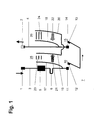
- Fig.7
- eine perspektivische Ansicht der als Konstruktion ausgeführten Strombahn des Leistungsschalters nach Fig.2.
- Fig.1
- 2 shows an equivalent circuit diagram of a current path of a circuit breaker according to the prior art with a double-interrupting contact arrangement,
- Fig. 2 to 6
- Equivalent circuit diagrams of current paths each one of five embodiment of the circuit breaker according to the invention, and
- Figure 7
- a perspective view of the current path of the circuit breaker designed as a construction according to Fig. 2.
In allen Figuren bezeichnen gleiche Bezugszeichen auch gleichwirkende Teile. Die
aus den Figuren 1 bis 6 ersichtlichen Ersatzschaltungen enthalten jeweils eine
zwischen zwei Stromanschlüssen 1, 2 verlaufende Strombahn 7 eines
Leistungsschalters. Bei allen Ersatzschaltungen weist diese Strombahn jeweils
einen mit dem Stromanschluss 1 bzw. 2 verbundenen Stromleiterabschnitt 3 bzw.
4 auf. Bei den Ersatzschaltungen nach den Figuren 1, 2 und 4 ist der
Stromleiterabschnitt 3 jeweils mit einem Kurzschlussstromauslöser 5,
beispielsweise mit einer Spule eines Schlagankers oder mit einem anderen
Magnetauslöser, verbunden. Der Kurzschlussstromauslöser 5 ist Teil einer nicht
dargestellten Auslösevorrichtung zur Betätigung einer zwei Kontaktsysteme 10, 15
enthaltenden Kontaktanordnung des Schalters.In all figures, the same reference symbols also designate parts with the same effect. The
equivalent circuits shown in FIGS. 1 to 6 each contain one
Bei der Ersatzschaltung nach Fig.1 ist der Kurzschlussstromauslöser 5 seinerseits
über einen Überstromauslöser 6, welcher als Bimetall oder als anderer thermischer
Auslöser ausgeführt sein kann und ebenfalls Teil der nicht dargestellten
Auslösevorrichtung ist, mit einem feststehenden Kontakt 11 des Kontaktsystems
10 verbunden. Auf einer nicht bezeichneten Kontaktbrücke sind ein beweglicher
Kontakt 12 des Kontaktsystems 10 und ein beweglicher Kontakt 13 des in Serie
mit dem Kontaktsystem 10 im Strompfad 3 liegenden Kontaktsystems 15
angeordnet. Ein feststehender Kontakt 14 des Kontaktsystems 15 ist mit dem
Stromleiter 4 verbunden.In the equivalent circuit according to Figure 1, the short-circuit
Bei den Ersatzschaltungen nach den Figuren 2 und 4 ist der
Kurzschlussstromauslöser 5 jeweils unmittelbar mit dem feststehenden Kontakt 11
des Kontaktsystems 10 verbunden. Der bewegliche Kontakt 12 des
Kontaktsystems 10 ist jeweils über einen flexibel ausgebildeten
Stromleiterabschnitt 25, beispielsweise eine Litze, mit dem Überstromauslöser 6
verbunden, welcher seinerseits jeweils über einen Zwischenleiterabschnitt 26 mit
dem feststehenden Kontakt 14 des Kontaktsystems 15 verbunden ist. Der
bewegliche Kontakt 13 des Kontaktsystems 15 ist jeweils über einen flexibel
ausgebildeten Stromleiterabschnitt 27, beispielsweise eine Litze, an den
Stromleiterabschnitt 4 angeschlossen.In the equivalent circuits according to Figures 2 and 4 is the
Short-circuit
Bei den Ersatzschaltungen nach den Figuren 3 und 5 ist der Stromleiterabschnitt 3
jeweils über den Überstromauslöser 6 und den flexibel ausgebildeten
Stromleiterabschnitt 25 mit dem beweglichen Kontakt 12 des Kontaktsystems 10
verbunden. Der feststehende Kontakt 11 des Kontaktsystems 10 ist über den
Kurzschlussstromauslöser 5 mit dem Zwischenleiterabschnitt 26 verbunden,
welcher seinerseits über den flexibel ausgebildeten Stromleiterabschnitt 27 an den
beweglichen Kontakt 13 des Kontaktsystems 15 angeschlossen ist. Der
feststehende Kontakt 14 des Kontaktsystems 15 ist an den Stromleiterabschnitt 4
angeschlossen.In the equivalent circuits according to FIGS. 3 and 5, the
Bei der Ersatzschaltung nach Figur 6 ist der Stromleiterabschnitt 3 über den
Überstromauslöser 6 mit dem feststehenden Kontakt 11 des Kontaktsystems 10
verbunden. Der bewegliche Kontakt 12 dieses Kontaktsystems ist über den
flexiblen Leiterabschnitt 25 und den Zwischenleiterabschnitt 26 mit dem
feststehenden Kontakt 14 des Kontaktsystems 15 verbunden. Der bewegliche
Kontakt 13 dieses Kontaktsystems ist über den flexibel ausgebildeten
Stromleiterabschnitt 27 und den Kurzschlussstromauslöser 5 an den
Stromleiterabschnitt 4 angeschlossen.In the equivalent circuit according to FIG. 6, the
Bei allen Ersatzschaltungen ist die Lichtbogenlaufschiene 17 bzw. 18 jeweils mit
einem nicht bezeichneten Kontaktträger des feststehenden Kontakts 11 bzw.14
verbunden.In all equivalent circuits, the
Bei der Ersatzschaltung des zum Stand der Technik zählenden Schalters gemäss
Fig.1 wirken die beweglichen Kontakte 12 bzw. 13 mit einer Lichtbogenlaufschiene
19 bzw. 20 zusammen. Die Lichtbogenlaufschienen 17, 19 sowie 18, 20 leiten bei
einem Ausschaltvorgang in den Kontaktsystemen 10, 15 gebildete
Schaltlichtbögen 21, 22 jeweils an ein Löschblechpaket 23 bzw. 24 einer
Lichtbogenlöschkammer 28 bzw. 29.In the equivalent circuit of the switch belonging to the prior art according to
Fig.1 act the
Bei der Ersatzschaltung nach Fig.2 ist die Lichtbogenlaufschiene 19 mit dem
Verbindungspunkt von Überstromauslöser 6 und Zwischenleiterabschnitt 26 und
die Lichtbogenlaufschiene 20 mit dem Stromleiterabschnitt 4 verbunden. Im
Unterschied dazu ist bei der Ersatzschaltung nach Fig.3 die Lichtbogenlaufschiene
19 mit dem Stromleiterabschnitt 3 und die Lichtbogenlaufschiene 20 mit dem
Verbindungspunkt von Zwischenleiterabschnitt 26 und flexibel ausgebildetem
Stromleiterabschnitt 27 verbunden. Beiden Ersatzschaltungen ist jedoch
gemeinsam, dass der Überstromauslöser 6 jeweils parallel zu einer von den
Lichtbogenlaufschienen 17 und 19 gebildeten und vom Lichtbogen 21
überbrückten Trennstrecke liegt.In the equivalent circuit according to Figure 2, the
Bei den Ersatzschaltungen nach den Figuren 4 und 5 ist die
Lichtbogenlaufschiene 19 jeweils mit dem Verbindungspunkt von
Überstromauslöser 6 und flexibel ausgebildetem Stromleiterabschnitt 25
verbunden. Die Lichtbogenlaufschiene 20 ist bei der Ersatzschaltung nach Fig.4
mit dem Stromleiterabschnitt 4 und bei der Ersatzschaltung nach Fig.5 mit dem
Zwischenleiterabschnitt 26 verbunden. Bei der Ersatzschaltung nach Fig.6 ist die
Lichtbogenlaufschiene 19 mit dem Verbindungspunkt von flexibel ausgebildetem
Stromleiterabschnitt 25 und Zwischenleiterabschnitt 26 und die
Lichtbogenlaufschiene 20 mit dem Verbindungspunkt von flexibel ausgebildetem
Stromleiterabschnitt 27 und Kurzschlussstromauslöser 5 verbunden. Diesen drei
Ersatzschaltungen ist gemeinsam, dass der Kurzschlussstromauslöser 5 und der
Überstromauslöser 6 in Serie zu der von den Lichtbogenlaufschienen 17 und 19
gebildeten und vom Lichtbogen 21 überbrückten Trennstrecke in der Strombahn
liegen.In the equivalent circuits according to Figures 4 and 5 is the
Bei allen durch die Ersatzschaltungen 1 bis 6 repräsentierten Schaltern sind die
jeweils das Löschblechpaket 23 bzw. 24 und zumindest Abschnitte der
Lichtbogenlaufschienen 17, 19 bzw. 18, 20 enthaltenden Löschkammern 28 bzw.
29 zueinander seitlich benachbart angeordnet. Die von den Lichtbögen 21 und 22
gebildeten elektromagnetischen Felder beeinflussen sich daher gegenseitig.In all the switches represented by the
Bei dem durch die Ersatzschaltung gemäss Fig. 1 dargestellten Leistungsschalter
nach dem Stand der Technik fliesst der abzuschaltende Strom - wie durch Pfeile
angegeben - vom Stromanschluss 1 über den Stromleiterabschnitt 3, den
Kurzschlussstromauslöser 5, den Überstromauslöser 6, die Kontaktsysteme 10
und 15 und den Stromleiterabschnitt 4 zum Stromanschluss 2. Beim Ausschalten
werden zwei von den Kontakten 11, 12 und 13, 14 auf die Lichtbogenlaufschienen
17, 19 und 18, 20 kommutierende Lichtbögen 21 und 22 gebildet. Ersichtlich
werden bei diesem Schalter die Lichtbögen gegensinnig vom abzuschaltenden
Strom durchflossen. Da die Löschkammern beider Kontaktsysteme 10 und 15
seitlich benachbart sind, stossen sich die Lichtbögen aufgrund von
elektrodynamischen Kräften voneinander ab. Ist einer der beiden Lichtbögen,
beispielsweise der Lichtbogen 21, etwas schwächer als der andere, beispielsweise
der Lichtbogen 22, so bremst der stärkere Lichtbogen 22 die Bewegung des
schwächeren Lichtbogens 21 auf den Lichtbogenlaufschienen 17, 19 oder
verhindert sogar dessen Einlauf in das Löschblechpaket 23. Hierdurch wird die
Abschaltleistung des Schalters nach dem Stand der Technik wesentlich limitiert.In the circuit breaker represented by the equivalent circuit shown in FIG. 1
according to the state of the art, the current to be switched off flows as if by arrows
specified - from the
Bei allen durch die Ersatzschaltungen gemäss den Figuren 2 bis 6 repräsentierten
Schaltern nach der Erfindung werden hingegen die beim Abschalten gebildeten
und auf die Lichtbogenlaufschienen 17, 19 und 18, 20 kommutierenden
Lichtbögen 21 und 22 gleichsinnig von abzuschaltenden Strom durchflossen.
Ersichtlich wird dies nicht dadurch erreicht, dass die beweglichen Kontakte 12 und
13 der beiden Kontaktsysteme 10 und 15 auf einer Kontaktbrücke angeordnet
sind, sondern dadurch, dass der bewegliche Kontakt 12 des Kontaktsystems 10
mit dem feststehenden Kontakt 14 des Kontaktsystems 15 elektrisch leitend
verbunden ist. Eine entsprechende Verbindung kann alternativ auch zwischen dem
beweglichen Kontakt 13 und dem feststehenden Kontakt 11 bestehen. In jedem
Fall weist diese Verbindung den aus den Figuren 2 bis 6 ersichtlichen
Zwischenleiterabschnitt 26 auf.In all represented by the equivalent circuits according to Figures 2 to 6
Switches according to the invention, however, are those formed when switching off
and commutating on the arc rails 17, 19 and 18, 20
Wie aus der in Fig.7 dargestellten konstruktiven Ausgestaltung der Strombahn 7
des durch die Ersatzschaltung gemäss Fig.2 repräsentierten Schalters nach der
Erfindung ersichtlich ist, ist dieser Zwischenleiterabschnitt 26 vorwiegend in der
Mitte zwischen den beiden Kontaktsystemen 10, 15 angeordnet. Er ist gewinkelt
ausgeführt. An das freie Ende eines aus Gründen der Übersichtlichkeit nicht
bezeichneten Schenkels des Winkels ist ein senkrecht zum Winkel geführter
Kontaktträger für den feststehenden Kontakt 14 angeformt. Der nach unten
geführte andere Schenkel des Winkels trägt an seinem seinem unteren Ende den
als Bimetallstreifen ausgeführten Überstromauslöser 6. Dieser Bimetallstreifen ist
in platzsparender Weise parallel zum vorgenannten Schenkel nach oben geführt
und an seinem oberen Ende mit dem als Litze, d. h. flexibel, ausgebildeten
Stromleiterabschnitt 25 verbunden. In entsprechender Weise ist der
Zwischenleiterabschnitt 26 auch beim Schalter nach Fig.4 ausgebildet und
angeordnet. As from the structural design of the
In Abänderung dieser Ausgestaltung kann der eine Schenkel des Winkels auch
über den flexibel ausgebildete Stromleiterabschnitt 27 mit dem beweglichen
Kontakt 13 und der andere Schenkel über die Spule des
Kurzschlussstromauslösers 5 mit dem feststehenden Kontakt 11 verbunden sein.
Diese Ausbildung ist bei den Schaltern gemäss den Figuren 3 und 5 vorgesehen.In a modification of this configuration, one leg of the angle can also
via the flexible
Eine fertigungstechnisch besonders vorteilhaft auszuführende Ausgestaltung der
Strombahn ist beim Schalter gemäss Fig.6 vorgesehen. Hier ist ein Schenkel des
Winkels über den flexibel ausgebildeten Stromleiterabschnitt 25 mit dem
beweglichen Kontakt 12 und der andere Schenkel mit dem feststehenden Kontakt
14 verbunden.A particularly advantageous embodiment of the manufacturing technology
Current path is provided for the switch according to Fig. 6. Here is a leg of the
Angle over the
Da nicht nur beim Schalter nach dem Stand der Technik, sondern auch bei den
erfindungsgemäss nach den Figuren 2 bis 6 ausgeführten Schaltern die
Löschkammern beider Kontaktsysteme 10 und 15 seitlich benachbart sind, ziehen
sich die gleichsinnig vom Abschaltstrom durchflossenen Lichtbögen 21, 22
aufgrund von elektrodynamischen Kräften an. Ist einer der beiden Lichtbögen,
beispielsweise der Lichtbogen 21, etwas schwächer als der andere, beispielsweise
der Lichtbogen 22, so zieht der stärkere Lichtbogen 22 den schwächeren
Lichtbogen 21 mit, beschleunigt dann dessen Bewegung auf den
Lichtbogenlaufschienen 17, 19 und verbessert zugleich auch dessen Einlauf in das
Löschblechpaket 23. Gegenüber einem vergleichbar bemessenen Schalter nach
dem Stand der Technik wird so das Ausschaltvermögen der erfindungsgemäss
ausgeführten Schalter verbessert.Because not only with the switch according to the prior art, but also with the
according to the invention according to FIGS. 2 to 6 switches
Arcing chambers of both
Dadurch, dass bei den Ausführungsformen des erfindungsgemässen Schalters
nach den Figuren 2 und 3 der Überstromauslöser 5 parallel zu der von den beiden
Lichtbogenlaufschiene, 17, 19 gebildeten und beim Ausschalten vom Lichtbogen
21 überbrückten Trennstrecke geschaltet ist, wird der vorzugsweise als
Bimetallement ausgebildete Überstromauslöser 6 nur kurzzeitig der Wirkung des
abzuschaltenden Stroms ausgesetzt. Der Überstromauslöser 6 kann daher
verhältnismässig schwach dimensionert sein.The fact that in the embodiments of the switch according to the invention
according to Figures 2 and 3, the
Sind der Überstromauslöser 6 und der in der Trennstrecke brennende Lichtbogen
21 hingegen wie bei den Ausführungsformen nach den Figuren 4 bis 6 in Serie
geschaltet, so addiert sich die Impedanz des Überstromauslösers 6 zu den
Impedanzen der Lichtbögen 21, 22 und unterstützt diese dann bei der
Strombegrenzung. Das Schaltvermögen des Leistungsschalters wird so zusätzlich
gesteigert.Are the
- 1, 21, 2
- Anschlussklemmenterminals
- 3, 43, 4
- StromleiterabschnitteCurrent conductor sections
- 55
- KurzschlussstromauslöserShort circuit current release
- 66
- ÜberstromauslöserOvercurrent release
- 77
- Strombahncurrent path
- 10, 1510, 15
- KontaktsystemeContact systems
- 11, 1411, 14
- feststehende Kontaktefixed contacts
- 12, 1312, 13
- bewegliche Kontaktemovable contacts
- 17, 18, 19, 2017, 18, 19, 20
- LichtbogenlaufschienenArc guide rails
- 21, 2221, 22
- Lichtbögenelectric arc
- 23, 2423, 24
- LöschblechpaketeArc splitter stacks
- 25, 2725, 27
- flexibel ausgebildete Stromleiterabschnitteflexibly trained conductor sections
- 2626
- ZwischenleiterabschnittBetween the line section
- 28, 2928, 29
- LichtbogenlöschkammernArc chutes
Claims (13)
dadurch gekennzeichnet, dass die Strombahn (7) einen Zwischenleiterabschnitt (26) enthält, welcher zwischen ein bewegliches Kontaktstück (12, 13) eines ersten beider Kontaktsysteme (10, 15) und ein feststehendes Kontaktstück (11, 14) des zweiten Kontaktsystems in die Strombahn geschaltet ist.Circuit breaker with a current path (7) containing two power connections (1, 2) and a double-interrupting contact arrangement, in which the contact arrangement contains two contact systems (10, 15) connected in series in the current path (7), each of which has two contact pieces which can move relative to one another (11, 12; 13, 14) and an arcing chamber (28, 29) which is arranged laterally adjacent to the arcing chamber of the other contact system,
characterized in that the current path (7) contains an intermediate conductor section (26) which between a movable contact piece (12, 13) of a first of the two contact systems (10, 15) and a fixed contact piece (11, 14) of the second contact system into the current path is switched.
Priority Applications (5)
| Application Number | Priority Date | Filing Date | Title |
|---|---|---|---|
| EP00811248A EP1220260A1 (en) | 2000-12-27 | 2000-12-27 | Circuit breaker with a double break contact arrangement |
| EP01271945A EP1346388A1 (en) | 2000-12-27 | 2001-12-20 | Power switch with a double breaking contact arrangement |
| PCT/CH2001/000735 WO2002052598A1 (en) | 2000-12-27 | 2001-12-20 | Power switch with a double breaking contact arrangement |
| CA002400387A CA2400387A1 (en) | 2000-12-27 | 2001-12-20 | Power switch with a double breaking contact arrangement |
| US10/203,904 US20030117246A1 (en) | 2000-12-27 | 2001-12-20 | Power switch with a double breaking contact arrangement |
Applications Claiming Priority (1)
| Application Number | Priority Date | Filing Date | Title |
|---|---|---|---|
| EP00811248A EP1220260A1 (en) | 2000-12-27 | 2000-12-27 | Circuit breaker with a double break contact arrangement |
Publications (1)
| Publication Number | Publication Date |
|---|---|
| EP1220260A1 true EP1220260A1 (en) | 2002-07-03 |
Family
ID=8175111
Family Applications (2)
| Application Number | Title | Priority Date | Filing Date |
|---|---|---|---|
| EP00811248A Withdrawn EP1220260A1 (en) | 2000-12-27 | 2000-12-27 | Circuit breaker with a double break contact arrangement |
| EP01271945A Withdrawn EP1346388A1 (en) | 2000-12-27 | 2001-12-20 | Power switch with a double breaking contact arrangement |
Family Applications After (1)
| Application Number | Title | Priority Date | Filing Date |
|---|---|---|---|
| EP01271945A Withdrawn EP1346388A1 (en) | 2000-12-27 | 2001-12-20 | Power switch with a double breaking contact arrangement |
Country Status (4)
| Country | Link |
|---|---|
| US (1) | US20030117246A1 (en) |
| EP (2) | EP1220260A1 (en) |
| CA (1) | CA2400387A1 (en) |
| WO (1) | WO2002052598A1 (en) |
Cited By (1)
| Publication number | Priority date | Publication date | Assignee | Title |
|---|---|---|---|---|
| WO2003001549A1 (en) * | 2001-06-22 | 2003-01-03 | Abb Service S.R.L. | Miniature circuit breaker pole |
Families Citing this family (1)
| Publication number | Priority date | Publication date | Assignee | Title |
|---|---|---|---|---|
| AU2002950581A0 (en) * | 2002-08-02 | 2002-09-12 | Wayne Callen | Electrical safety circuit |
Citations (4)
| Publication number | Priority date | Publication date | Assignee | Title |
|---|---|---|---|---|
| CH543174A (en) * | 1971-09-30 | 1973-10-15 | Carl Maier & Cie Elek Sche Sch | Circuit breaker |
| EP0418754A2 (en) * | 1989-09-18 | 1991-03-27 | Mitsubishi Denki Kabushiki Kaisha | Current limiting apparatus |
| EP0619592A1 (en) * | 1993-04-07 | 1994-10-12 | Schneider Electric Sa | Electric circuit breaker with electrodynamic repulsion of the contacts and double extinguishing chambers |
| EP0649155A1 (en) * | 1993-10-15 | 1995-04-19 | Hager Electro S.A. | Double arc runner for a circuit breaker arc guide chamber |
Family Cites Families (2)
| Publication number | Priority date | Publication date | Assignee | Title |
|---|---|---|---|---|
| JPH10285037A (en) * | 1997-04-10 | 1998-10-23 | Mitsubishi Electric Corp | Analog to digital converter circuit |
| US5874873A (en) * | 1997-08-22 | 1999-02-23 | Eaton Corporation | Electric control apparatus |
-
2000
- 2000-12-27 EP EP00811248A patent/EP1220260A1/en not_active Withdrawn
-
2001
- 2001-12-20 US US10/203,904 patent/US20030117246A1/en not_active Abandoned
- 2001-12-20 WO PCT/CH2001/000735 patent/WO2002052598A1/en not_active Application Discontinuation
- 2001-12-20 CA CA002400387A patent/CA2400387A1/en not_active Abandoned
- 2001-12-20 EP EP01271945A patent/EP1346388A1/en not_active Withdrawn
Patent Citations (4)
| Publication number | Priority date | Publication date | Assignee | Title |
|---|---|---|---|---|
| CH543174A (en) * | 1971-09-30 | 1973-10-15 | Carl Maier & Cie Elek Sche Sch | Circuit breaker |
| EP0418754A2 (en) * | 1989-09-18 | 1991-03-27 | Mitsubishi Denki Kabushiki Kaisha | Current limiting apparatus |
| EP0619592A1 (en) * | 1993-04-07 | 1994-10-12 | Schneider Electric Sa | Electric circuit breaker with electrodynamic repulsion of the contacts and double extinguishing chambers |
| EP0649155A1 (en) * | 1993-10-15 | 1995-04-19 | Hager Electro S.A. | Double arc runner for a circuit breaker arc guide chamber |
Cited By (1)
| Publication number | Priority date | Publication date | Assignee | Title |
|---|---|---|---|---|
| WO2003001549A1 (en) * | 2001-06-22 | 2003-01-03 | Abb Service S.R.L. | Miniature circuit breaker pole |
Also Published As
| Publication number | Publication date |
|---|---|
| CA2400387A1 (en) | 2002-07-04 |
| US20030117246A1 (en) | 2003-06-26 |
| WO2002052598A1 (en) | 2002-07-04 |
| EP1346388A1 (en) | 2003-09-24 |
Similar Documents
| Publication | Publication Date | Title |
|---|---|---|
| EP2383761A1 (en) | Switching device for direct current applications | |
| EP2649629A1 (en) | Switch having a quenching chamber | |
| DE112007003283T5 (en) | Double break contact system for a low voltage circuit breaker and the double break contact system comprising molded case circuit breaker | |
| EP0150486B1 (en) | Electric circuit breaker | |
| EP1683173B1 (en) | Arc quenching system | |
| EP1735803B1 (en) | Switching device | |
| EP0350825B1 (en) | Electrical switch gear | |
| EP3428942B1 (en) | Direct current device for eliminating arcing and electromechanical direct current switching device | |
| DE4335965A1 (en) | Motor starter (engine starter) having integrated short-circuit protection | |
| EP2030211A1 (en) | Power switch or power protective switch | |
| DE10291133B4 (en) | Housing for a switching device | |
| DE19903837B4 (en) | Self-recovering current limiting device with liquid metal | |
| US4562320A (en) | Current-limiting device | |
| EP1220260A1 (en) | Circuit breaker with a double break contact arrangement | |
| DE2234423A1 (en) | AUTOMATIC INSTALLATION SWITCH IN SHELL CONSTRUCTION | |
| EP2393096B1 (en) | Easy to interrupt low voltage circuit breaker, in particular current protection switch | |
| EP2541574B1 (en) | Double interrupter protective switch device | |
| DE2751452C2 (en) | Electrical switchgear | |
| EP3889986B1 (en) | Electromechanical compact protective switching device | |
| DE2826243A1 (en) | Switch with arc extinguishing chamber - has fixed contacts on conducting plates and movable contacts on levers connected together | |
| EP1615246A1 (en) | Arc extinguishing device for circuit breaker | |
| AT402583B (en) | CIRCUIT BREAKER WITH A THERMALLY AND MAGNETICALLY PROTECTED OUTER POLE AND AN UNprotected Neutral Pole | |
| DE3034189C2 (en) | Two-pole low-voltage circuit breaker with single break and electrodynamic compensation of the contact opening forces | |
| DE19734676A1 (en) | Line protection switch with two series-connected switch points | |
| DE102020210028A1 (en) | Operator-independent compact snap-action switch and electromechanical protective switching device |
Legal Events
| Date | Code | Title | Description |
|---|---|---|---|
| PUAI | Public reference made under article 153(3) epc to a published international application that has entered the european phase |
Free format text: ORIGINAL CODE: 0009012 |
|
| AK | Designated contracting states |
Kind code of ref document: A1 Designated state(s): AT BE CH CY DE DK ES FI FR GB GR IE IT LI LU MC NL PT SE TR |
|
| AX | Request for extension of the european patent |
Free format text: AL;LT;LV;MK;RO;SI |
|
| AKX | Designation fees paid | ||
| REG | Reference to a national code |
Ref country code: DE Ref legal event code: 8566 |
|
| STAA | Information on the status of an ep patent application or granted ep patent |
Free format text: STATUS: THE APPLICATION IS DEEMED TO BE WITHDRAWN |
|
| 18D | Application deemed to be withdrawn |
Effective date: 20030104 |