EP2060464A2 - Système d'assistance pour l'empêchement de collision en avant - Google Patents
Système d'assistance pour l'empêchement de collision en avant Download PDFInfo
- Publication number
- EP2060464A2 EP2060464A2 EP08019957A EP08019957A EP2060464A2 EP 2060464 A2 EP2060464 A2 EP 2060464A2 EP 08019957 A EP08019957 A EP 08019957A EP 08019957 A EP08019957 A EP 08019957A EP 2060464 A2 EP2060464 A2 EP 2060464A2
- Authority
- EP
- European Patent Office
- Prior art keywords
- collision
- avoidable
- jerk
- distance
- lateral
- Prior art date
- Legal status (The legal status is an assumption and is not a legal conclusion. Google has not performed a legal analysis and makes no representation as to the accuracy of the status listed.)
- Withdrawn
Links
- 230000001133 acceleration Effects 0.000 claims abstract description 217
- 230000036461 convulsion Effects 0.000 claims abstract description 200
- 238000001514 detection method Methods 0.000 claims abstract description 40
- 230000006872 improvement Effects 0.000 abstract description 6
- 230000009467 reduction Effects 0.000 abstract description 6
- 238000012545 processing Methods 0.000 description 54
- 230000008859 change Effects 0.000 description 45
- 238000000034 method Methods 0.000 description 33
- 238000010586 diagram Methods 0.000 description 12
- 230000007246 mechanism Effects 0.000 description 11
- 230000004044 response Effects 0.000 description 9
- 230000035939 shock Effects 0.000 description 7
- 238000004891 communication Methods 0.000 description 5
- 239000012530 fluid Substances 0.000 description 3
- 230000003247 decreasing effect Effects 0.000 description 2
- 230000000694 effects Effects 0.000 description 2
- 238000003384 imaging method Methods 0.000 description 2
- 238000005259 measurement Methods 0.000 description 2
- 210000003462 vein Anatomy 0.000 description 2
- NAWXUBYGYWOOIX-SFHVURJKSA-N (2s)-2-[[4-[2-(2,4-diaminoquinazolin-6-yl)ethyl]benzoyl]amino]-4-methylidenepentanedioic acid Chemical compound C1=CC2=NC(N)=NC(N)=C2C=C1CCC1=CC=C(C(=O)N[C@@H](CC(=C)C(O)=O)C(O)=O)C=C1 NAWXUBYGYWOOIX-SFHVURJKSA-N 0.000 description 1
- 238000012986 modification Methods 0.000 description 1
- 230000004048 modification Effects 0.000 description 1
- 230000001172 regenerating effect Effects 0.000 description 1
- 230000011664 signaling Effects 0.000 description 1
- 230000000007 visual effect Effects 0.000 description 1
Images


Classifications
-
- B—PERFORMING OPERATIONS; TRANSPORTING
- B60—VEHICLES IN GENERAL
- B60W—CONJOINT CONTROL OF VEHICLE SUB-UNITS OF DIFFERENT TYPE OR DIFFERENT FUNCTION; CONTROL SYSTEMS SPECIALLY ADAPTED FOR HYBRID VEHICLES; ROAD VEHICLE DRIVE CONTROL SYSTEMS FOR PURPOSES NOT RELATED TO THE CONTROL OF A PARTICULAR SUB-UNIT
- B60W30/00—Purposes of road vehicle drive control systems not related to the control of a particular sub-unit, e.g. of systems using conjoint control of vehicle sub-units
- B60W30/02—Control of vehicle driving stability
-
- B—PERFORMING OPERATIONS; TRANSPORTING
- B60—VEHICLES IN GENERAL
- B60T—VEHICLE BRAKE CONTROL SYSTEMS OR PARTS THEREOF; BRAKE CONTROL SYSTEMS OR PARTS THEREOF, IN GENERAL; ARRANGEMENT OF BRAKING ELEMENTS ON VEHICLES IN GENERAL; PORTABLE DEVICES FOR PREVENTING UNWANTED MOVEMENT OF VEHICLES; VEHICLE MODIFICATIONS TO FACILITATE COOLING OF BRAKES
- B60T7/00—Brake-action initiating means
- B60T7/12—Brake-action initiating means for automatic initiation; for initiation not subject to will of driver or passenger
- B60T7/22—Brake-action initiating means for automatic initiation; for initiation not subject to will of driver or passenger initiated by contact of vehicle, e.g. bumper, with an external object, e.g. another vehicle, or by means of contactless obstacle detectors mounted on the vehicle
-
- B—PERFORMING OPERATIONS; TRANSPORTING
- B60—VEHICLES IN GENERAL
- B60T—VEHICLE BRAKE CONTROL SYSTEMS OR PARTS THEREOF; BRAKE CONTROL SYSTEMS OR PARTS THEREOF, IN GENERAL; ARRANGEMENT OF BRAKING ELEMENTS ON VEHICLES IN GENERAL; PORTABLE DEVICES FOR PREVENTING UNWANTED MOVEMENT OF VEHICLES; VEHICLE MODIFICATIONS TO FACILITATE COOLING OF BRAKES
- B60T8/00—Arrangements for adjusting wheel-braking force to meet varying vehicular or ground-surface conditions, e.g. limiting or varying distribution of braking force
- B60T8/17—Using electrical or electronic regulation means to control braking
- B60T8/1755—Brake regulation specially adapted to control the stability of the vehicle, e.g. taking into account yaw rate or transverse acceleration in a curve
- B60T8/17558—Brake regulation specially adapted to control the stability of the vehicle, e.g. taking into account yaw rate or transverse acceleration in a curve specially adapted for collision avoidance or collision mitigation
-
- B—PERFORMING OPERATIONS; TRANSPORTING
- B60—VEHICLES IN GENERAL
- B60W—CONJOINT CONTROL OF VEHICLE SUB-UNITS OF DIFFERENT TYPE OR DIFFERENT FUNCTION; CONTROL SYSTEMS SPECIALLY ADAPTED FOR HYBRID VEHICLES; ROAD VEHICLE DRIVE CONTROL SYSTEMS FOR PURPOSES NOT RELATED TO THE CONTROL OF A PARTICULAR SUB-UNIT
- B60W10/00—Conjoint control of vehicle sub-units of different type or different function
- B60W10/04—Conjoint control of vehicle sub-units of different type or different function including control of propulsion units
- B60W10/06—Conjoint control of vehicle sub-units of different type or different function including control of propulsion units including control of combustion engines
-
- B—PERFORMING OPERATIONS; TRANSPORTING
- B60—VEHICLES IN GENERAL
- B60W—CONJOINT CONTROL OF VEHICLE SUB-UNITS OF DIFFERENT TYPE OR DIFFERENT FUNCTION; CONTROL SYSTEMS SPECIALLY ADAPTED FOR HYBRID VEHICLES; ROAD VEHICLE DRIVE CONTROL SYSTEMS FOR PURPOSES NOT RELATED TO THE CONTROL OF A PARTICULAR SUB-UNIT
- B60W10/00—Conjoint control of vehicle sub-units of different type or different function
- B60W10/18—Conjoint control of vehicle sub-units of different type or different function including control of braking systems
- B60W10/184—Conjoint control of vehicle sub-units of different type or different function including control of braking systems with wheel brakes
-
- B—PERFORMING OPERATIONS; TRANSPORTING
- B60—VEHICLES IN GENERAL
- B60W—CONJOINT CONTROL OF VEHICLE SUB-UNITS OF DIFFERENT TYPE OR DIFFERENT FUNCTION; CONTROL SYSTEMS SPECIALLY ADAPTED FOR HYBRID VEHICLES; ROAD VEHICLE DRIVE CONTROL SYSTEMS FOR PURPOSES NOT RELATED TO THE CONTROL OF A PARTICULAR SUB-UNIT
- B60W10/00—Conjoint control of vehicle sub-units of different type or different function
- B60W10/20—Conjoint control of vehicle sub-units of different type or different function including control of steering systems
-
- B—PERFORMING OPERATIONS; TRANSPORTING
- B60—VEHICLES IN GENERAL
- B60W—CONJOINT CONTROL OF VEHICLE SUB-UNITS OF DIFFERENT TYPE OR DIFFERENT FUNCTION; CONTROL SYSTEMS SPECIALLY ADAPTED FOR HYBRID VEHICLES; ROAD VEHICLE DRIVE CONTROL SYSTEMS FOR PURPOSES NOT RELATED TO THE CONTROL OF A PARTICULAR SUB-UNIT
- B60W30/00—Purposes of road vehicle drive control systems not related to the control of a particular sub-unit, e.g. of systems using conjoint control of vehicle sub-units
- B60W30/08—Active safety systems predicting or avoiding probable or impending collision or attempting to minimise its consequences
- B60W30/09—Taking automatic action to avoid collision, e.g. braking and steering
-
- B—PERFORMING OPERATIONS; TRANSPORTING
- B60—VEHICLES IN GENERAL
- B60W—CONJOINT CONTROL OF VEHICLE SUB-UNITS OF DIFFERENT TYPE OR DIFFERENT FUNCTION; CONTROL SYSTEMS SPECIALLY ADAPTED FOR HYBRID VEHICLES; ROAD VEHICLE DRIVE CONTROL SYSTEMS FOR PURPOSES NOT RELATED TO THE CONTROL OF A PARTICULAR SUB-UNIT
- B60W30/00—Purposes of road vehicle drive control systems not related to the control of a particular sub-unit, e.g. of systems using conjoint control of vehicle sub-units
- B60W30/08—Active safety systems predicting or avoiding probable or impending collision or attempting to minimise its consequences
- B60W30/095—Predicting travel path or likelihood of collision
-
- B—PERFORMING OPERATIONS; TRANSPORTING
- B60—VEHICLES IN GENERAL
- B60W—CONJOINT CONTROL OF VEHICLE SUB-UNITS OF DIFFERENT TYPE OR DIFFERENT FUNCTION; CONTROL SYSTEMS SPECIALLY ADAPTED FOR HYBRID VEHICLES; ROAD VEHICLE DRIVE CONTROL SYSTEMS FOR PURPOSES NOT RELATED TO THE CONTROL OF A PARTICULAR SUB-UNIT
- B60W30/00—Purposes of road vehicle drive control systems not related to the control of a particular sub-unit, e.g. of systems using conjoint control of vehicle sub-units
- B60W30/18—Propelling the vehicle
- B60W30/18009—Propelling the vehicle related to particular drive situations
- B60W30/18109—Braking
- B60W30/18136—Engine braking
-
- B—PERFORMING OPERATIONS; TRANSPORTING
- B60—VEHICLES IN GENERAL
- B60W—CONJOINT CONTROL OF VEHICLE SUB-UNITS OF DIFFERENT TYPE OR DIFFERENT FUNCTION; CONTROL SYSTEMS SPECIALLY ADAPTED FOR HYBRID VEHICLES; ROAD VEHICLE DRIVE CONTROL SYSTEMS FOR PURPOSES NOT RELATED TO THE CONTROL OF A PARTICULAR SUB-UNIT
- B60W50/00—Details of control systems for road vehicle drive control not related to the control of a particular sub-unit, e.g. process diagnostic or vehicle driver interfaces
- B60W50/08—Interaction between the driver and the control system
- B60W50/14—Means for informing the driver, warning the driver or prompting a driver intervention
-
- B—PERFORMING OPERATIONS; TRANSPORTING
- B60—VEHICLES IN GENERAL
- B60T—VEHICLE BRAKE CONTROL SYSTEMS OR PARTS THEREOF; BRAKE CONTROL SYSTEMS OR PARTS THEREOF, IN GENERAL; ARRANGEMENT OF BRAKING ELEMENTS ON VEHICLES IN GENERAL; PORTABLE DEVICES FOR PREVENTING UNWANTED MOVEMENT OF VEHICLES; VEHICLE MODIFICATIONS TO FACILITATE COOLING OF BRAKES
- B60T2201/00—Particular use of vehicle brake systems; Special systems using also the brakes; Special software modules within the brake system controller
- B60T2201/02—Active or adaptive cruise control system; Distance control
- B60T2201/022—Collision avoidance systems
-
- B—PERFORMING OPERATIONS; TRANSPORTING
- B60—VEHICLES IN GENERAL
- B60W—CONJOINT CONTROL OF VEHICLE SUB-UNITS OF DIFFERENT TYPE OR DIFFERENT FUNCTION; CONTROL SYSTEMS SPECIALLY ADAPTED FOR HYBRID VEHICLES; ROAD VEHICLE DRIVE CONTROL SYSTEMS FOR PURPOSES NOT RELATED TO THE CONTROL OF A PARTICULAR SUB-UNIT
- B60W2510/00—Input parameters relating to a particular sub-units
- B60W2510/18—Braking system
- B60W2510/182—Brake pressure, e.g. of fluid or between pad and disc
-
- B—PERFORMING OPERATIONS; TRANSPORTING
- B60—VEHICLES IN GENERAL
- B60W—CONJOINT CONTROL OF VEHICLE SUB-UNITS OF DIFFERENT TYPE OR DIFFERENT FUNCTION; CONTROL SYSTEMS SPECIALLY ADAPTED FOR HYBRID VEHICLES; ROAD VEHICLE DRIVE CONTROL SYSTEMS FOR PURPOSES NOT RELATED TO THE CONTROL OF A PARTICULAR SUB-UNIT
- B60W2520/00—Input parameters relating to overall vehicle dynamics
- B60W2520/10—Longitudinal speed
- B60W2520/105—Longitudinal acceleration
-
- B—PERFORMING OPERATIONS; TRANSPORTING
- B60—VEHICLES IN GENERAL
- B60W—CONJOINT CONTROL OF VEHICLE SUB-UNITS OF DIFFERENT TYPE OR DIFFERENT FUNCTION; CONTROL SYSTEMS SPECIALLY ADAPTED FOR HYBRID VEHICLES; ROAD VEHICLE DRIVE CONTROL SYSTEMS FOR PURPOSES NOT RELATED TO THE CONTROL OF A PARTICULAR SUB-UNIT
- B60W2520/00—Input parameters relating to overall vehicle dynamics
- B60W2520/12—Lateral speed
- B60W2520/125—Lateral acceleration
-
- B—PERFORMING OPERATIONS; TRANSPORTING
- B60—VEHICLES IN GENERAL
- B60W—CONJOINT CONTROL OF VEHICLE SUB-UNITS OF DIFFERENT TYPE OR DIFFERENT FUNCTION; CONTROL SYSTEMS SPECIALLY ADAPTED FOR HYBRID VEHICLES; ROAD VEHICLE DRIVE CONTROL SYSTEMS FOR PURPOSES NOT RELATED TO THE CONTROL OF A PARTICULAR SUB-UNIT
- B60W2540/00—Input parameters relating to occupants
- B60W2540/18—Steering angle
-
- B—PERFORMING OPERATIONS; TRANSPORTING
- B60—VEHICLES IN GENERAL
- B60W—CONJOINT CONTROL OF VEHICLE SUB-UNITS OF DIFFERENT TYPE OR DIFFERENT FUNCTION; CONTROL SYSTEMS SPECIALLY ADAPTED FOR HYBRID VEHICLES; ROAD VEHICLE DRIVE CONTROL SYSTEMS FOR PURPOSES NOT RELATED TO THE CONTROL OF A PARTICULAR SUB-UNIT
- B60W2552/00—Input parameters relating to infrastructure
- B60W2552/40—Coefficient of friction
-
- B—PERFORMING OPERATIONS; TRANSPORTING
- B60—VEHICLES IN GENERAL
- B60W—CONJOINT CONTROL OF VEHICLE SUB-UNITS OF DIFFERENT TYPE OR DIFFERENT FUNCTION; CONTROL SYSTEMS SPECIALLY ADAPTED FOR HYBRID VEHICLES; ROAD VEHICLE DRIVE CONTROL SYSTEMS FOR PURPOSES NOT RELATED TO THE CONTROL OF A PARTICULAR SUB-UNIT
- B60W2554/00—Input parameters relating to objects
- B60W2554/80—Spatial relation or speed relative to objects
- B60W2554/801—Lateral distance
-
- B—PERFORMING OPERATIONS; TRANSPORTING
- B60—VEHICLES IN GENERAL
- B60W—CONJOINT CONTROL OF VEHICLE SUB-UNITS OF DIFFERENT TYPE OR DIFFERENT FUNCTION; CONTROL SYSTEMS SPECIALLY ADAPTED FOR HYBRID VEHICLES; ROAD VEHICLE DRIVE CONTROL SYSTEMS FOR PURPOSES NOT RELATED TO THE CONTROL OF A PARTICULAR SUB-UNIT
- B60W2554/00—Input parameters relating to objects
- B60W2554/80—Spatial relation or speed relative to objects
- B60W2554/804—Relative longitudinal speed
-
- B—PERFORMING OPERATIONS; TRANSPORTING
- B60—VEHICLES IN GENERAL
- B60W—CONJOINT CONTROL OF VEHICLE SUB-UNITS OF DIFFERENT TYPE OR DIFFERENT FUNCTION; CONTROL SYSTEMS SPECIALLY ADAPTED FOR HYBRID VEHICLES; ROAD VEHICLE DRIVE CONTROL SYSTEMS FOR PURPOSES NOT RELATED TO THE CONTROL OF A PARTICULAR SUB-UNIT
- B60W2710/00—Output or target parameters relating to a particular sub-units
- B60W2710/06—Combustion engines, Gas turbines
- B60W2710/0605—Throttle position
-
- B—PERFORMING OPERATIONS; TRANSPORTING
- B60—VEHICLES IN GENERAL
- B60W—CONJOINT CONTROL OF VEHICLE SUB-UNITS OF DIFFERENT TYPE OR DIFFERENT FUNCTION; CONTROL SYSTEMS SPECIALLY ADAPTED FOR HYBRID VEHICLES; ROAD VEHICLE DRIVE CONTROL SYSTEMS FOR PURPOSES NOT RELATED TO THE CONTROL OF A PARTICULAR SUB-UNIT
- B60W2710/00—Output or target parameters relating to a particular sub-units
- B60W2710/18—Braking system
- B60W2710/182—Brake pressure, e.g. of fluid or between pad and disc
-
- B—PERFORMING OPERATIONS; TRANSPORTING
- B60—VEHICLES IN GENERAL
- B60W—CONJOINT CONTROL OF VEHICLE SUB-UNITS OF DIFFERENT TYPE OR DIFFERENT FUNCTION; CONTROL SYSTEMS SPECIALLY ADAPTED FOR HYBRID VEHICLES; ROAD VEHICLE DRIVE CONTROL SYSTEMS FOR PURPOSES NOT RELATED TO THE CONTROL OF A PARTICULAR SUB-UNIT
- B60W2710/00—Output or target parameters relating to a particular sub-units
- B60W2710/20—Steering systems
- B60W2710/207—Steering angle of wheels
Definitions
- the present invention relates to a forward collision avoidance assistance system that detects an object existing ahead of a host vehicle and, if the host vehicle is judged to have the possibility of contact with the object, automatically generates brake force, lateral force, and the like in the vehicle.
- JP-A-6-298022 discloses a known technique for automatically actuating brake if the distance to a preceding vehicle becomes equal to or smaller than the braking-based collision-avoidable limit distance that can prevent contact with the preceding vehicle by braking operation and the steering-based collision-avoidable limit distance that can prevent contact with the preceding vehicle by steering operation.
- JP-A-11-203598 discloses a known technique for actuating brake if steering-based collision avoidance of contact with an object is judged to be impossible, that is, if the relative distance to the object becomes equal to or smaller than the steering-based collision-avoidable limit distance.
- JP-A-2003-182544 discloses a known technique for starting a gradual increase in brake fluid pressure if either braking-based collision avoidance of contact with an object or steering-based collision avoidance of contact with an object is judged to be impossible, that is, if the distance to a preceding vehicle becomes equal to or smaller than the braking-based collision-avoidable limit distance or the steering-based collision-avoidable limit distance, and increasing the brake pressure to a predetermined pressure if neither braking-based collision avoidance of contact with an object nor steering-based collision avoidance of contact with an object is judged to be possible.
- the possibility of contact with the object can be reduced while preventing braking-based deceleration from occurring at an inappropriate timing.
- any of the above-mentioned techniques determines timing for generating brake force based on the braking-based collision-avoidable limit distance or the steering-based collision-avoidable limit distance, and therefore does not sufficiently reduce driver's uncomfortable feeling or improve the drivability.
- JP-A-2003-182544 reduces driver's uncomfortable feeling by gradually increasing the brake fluid pressure if the relative distance to an object falls below the braking-based collision-avoidable limit distance or the steering-based collision-avoidable limit distance. For example, under a condition where the braking-based collision-avoidable limit distance nearly equals the steering-based collision-avoidable limit distance, the brake fluid pressure may steeply increase and therefore it cannot be said that driver's uncomfortable feeling is sufficiently reduced.
- jerk change rate of acceleration
- An object of the present invention is to provide a forward collision avoidance assistance system that attains the reduction of driver's uncomfortable feeling and the improvement in drivability while ensuring the collision avoidance performance during operation for avoiding contact with an object.
- the present invention can reduce driver's uncomfortable feeling and improve the drivability while ensuring the collision avoidance performance during operation for avoiding contact with an object.
- Fig. 1 is a system block diagram showing the configuration of the forward collision avoidance assistance system according to the first embodiment.
- the forward collision avoidance assistance system of the present embodiment is to be mounted on a vehicle.
- the system comprises a host vehicle information detection unit 1 for obtaining the operating state of the host vehicle and the operational variables set by the driver; an object information detection unit 2 for detecting an object existing in the host vehicle traveling direction; a collision avoidance calculation unit 3 for calculating the risk level of the host vehicle colliding with the object and for giving commands to an alarm unit 4, a brake actuator 5, and a tail-light 6; the alarm unit 4 for warning the driver based on a command from the collision avoidance calculation unit 3; a brake actuator 5 for generating brake force for each tire; and a tail-light 6 (or a stop-light) for signaling the deceleration of the host vehicle to a following vehicle.
- Input to the host vehicle information detection unit 1 are a steering angle ⁇ , a vehicle velocity V1_0, a vehicle longitudinal acceleration rate Gx1_0, a vehicle lateral acceleration rate Gy1_0, a master brake pressure Pm, etc.
- the vehicle velocity V1_0 can be estimated from tire speeds or can be directly measured using an external sensor or the like.
- the operational variables set by the driver are obtained with the use of a steering torque, a brake pedal stroke amount, or the like.
- Input to the object information detection unit 2 are the relative distance between the host vehicle and the object existing in the host vehicle traveling direction (the distance represented by ⁇ x), an object velocity V2_0, an object acceleration rate Gx2_0, the object width, and the offset amount between the center of the host vehicle and that of the object (the amount represented by ⁇ y).
- Those variables can be calculated from continuous images obtained by a CCD imaging element or other imaging devices or can be detected with the use of a millimeter-wave radar, a laser radar, or the like.
- the collision avoidance calculation unit 3 calculates a collision-avoidable limit distance and a jerk-limited collision avoidable distance based on the steering angle ⁇ , the vehicle velocity V1_0, the vehicle longitudinal acceleration rate Gx1_0, the vehicle lateral acceleration rate Gy1_0, and the master brake pressure Pm, all of which are obtained by the host vehicle information detection unit 1 and based on the relative distance ⁇ x0 between the object and the host vehicle, the object velocity V2_0, and the object acceleration rate Gx2_0, all of which are obtained by the object information detection unit 2. Based on the collision-avoidable limit distance and the jerk-limited collision avoidable distance, the collision avoidance calculation unit 3 further calculates the risk of collision between the host vehicle and the object. The collision avoidance calculation unit 3 also calculates drive control variables for the alarm unit 4, the brake actuator 5, and the tail-light 6 based on the risk of collision.
- the collision avoidability region of the host vehicle is divided into nine regions based on the collision-avoidable limit distance and the jerk-limited collision avoidable distance in relation to the relative velocity between the host vehicle and the object.
- the collision avoidance calculation unit 3 determines a collision avoidability region the host vehicle is in based on a calculated collision-avoidable limit distance and jerk-limited collision avoidable distance and performs collision avoidance control suitable for that region.
- the collision-avoidable limit distance ⁇ xctl2 is obtained from a deceleration-based collision-avoidable limit distance ⁇ xbrk and a lateral-motion-based collision-avoidable limit distance ⁇ xstr in relation to a relative velocity ⁇ V0.
- the jerk-limited collision avoidable distance ⁇ xctl1 is obtained from a jerk-limited deceleration-based collision avoidable distance ⁇ xbrklmt and a jerk-limited lateral-motion-based collision avoidable distance ⁇ xstrlmt in relation to the relative velocity ⁇ V0.
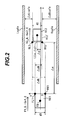
- Fig. 2 is a diagram of the positional relation between the host vehicle and an object ahead of the vehicle, explaining the calculations of the collision-avoidable limit distance and the jerk-limited collision avoidable distance between them, which calculations are performed by the forward collision avoidance assistance system according to the first embodiment.
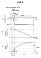
- Figs. 3A, 3B, and 3C are graphs respectively showing the deceleration of the host vehicle, the relative velocity between the host vehicle and the object existing in the host vehicle traveling direction, and the travel distance of the host vehicle for explaining the forward collision avoidance assistance system according to the first embodiment.
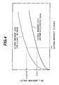
- Fig. 4 is a graph showing the relation between the lateral-movement distance and the lateral-movement duration of the host vehicle for explaining the forward collision avoidance assistance system according to the first embodiment.
- Fig. 5 is a graph showing the relation between the relative velocity between the host vehicle and the object existing in the host vehicle traveling direction and the collision-avoidable limit distance for explaining the forward collision avoidance assistance system according to the first embodiment.
- Fig. 2 assume that an object VE2 exists ahead of a host vehicle VE1.
- the host vehicle VE1 is moving at the vehicle velocity V1_0 and a vehicle longitudinal acceleration rate -Gx1_0, and the object is moving at the vehicle velocity V2_0 and a vehicle longitudinal acceleration rate -Gx2_0.
- the midpoint between the front right corner FR1 and the front left corner FLl of the host vehicle VE1 is the origin.
- the forward direction of the host vehicle VE1 is the x direction
- the direction perpendicularly intersecting the x direction is the y direction
- the traveling direction of the host vehicle VE1 and the left direction with respect to the traveling direction are positive.
- a collision risk area VE2' is an area formed by expanding the object VE2 laterally and longitudinally.
- d1 denotes the y-directional width of the host vehicle VE1
- d2 denotes the y-directional width of the collision risk area VE2'
- ( ⁇ x, Ay) denotes the coordinates of the midpoint between the rear left corner RL2 and the rear right corner RR2 of the collision risk area VE2'.
- Ay denotes the y-directional offset amount of the midpoint of the collision risk area VE2' with respect to the midpoint of the host vehicle VE1.
- the y-directional offset amount ⁇ y becomes negative; if the midpoint of the collision risk area VE2' exists to the left of the midpoint of the host vehicle VE1, the y-directional offset amount ⁇ y becomes positive.
- the offset amount ⁇ dR between the front left corner FL1 and the rear right corner RR2 and the offset amount ⁇ dL between the front right corner FR1 and the rear left corner RL2 are represented by the following Formulas (1) and (2), respectively.
- Formula 1 ⁇ dR d 1 2 + d 2 2 - ⁇ y
- Formula 2 ⁇ dL d 1 2 + d 2 2 + ⁇ y
- the relative velocity ⁇ V0 and the relative acceleration ⁇ Gx0 between the host vehicle VE1 and the object VE2 are represented by the following Formulas (3) and (4), respectively.
- Formula 3 ⁇ V ⁇ 0 V ⁇ 1 _ 0 - V ⁇ 2 _ 0
- Formula 4 ⁇ Gx ⁇ 0 - Gx ⁇ 1 _ 0 ) ( - , , - , Gx , , 2 , _ , 0
- V1_0 denotes the velocity of the host vehicle VE1
- V2_0 the velocity of the object VE2.
- (-Gx1_0) denotes the acceleration of the host vehicle VE1
- (-Gx2_0) the acceleration of the object VE2.
- the host vehicle VE1 might collide with the object VE2.
- Methods for avoiding this collision include deceleration-based collision avoidance and lateral-motion-based collision avoidance.
- Fig. 3A shows the acceleration (-Gx1_0) of the host vehicle VE1
- Fig. 3B shows the relative velocity ⁇ V0 between the host vehicle VE1 and the object VE2
- Fig. 3C shows the relative distance x between the host vehicle VE1 and the object VE2.
- the horizontal axis of Figs. 3A to 3C denotes time t.
- the travel distance shown in Fig. 3C reaches the deceleration-based collision-avoidable limit distance ⁇ xbrk, i.e., a physical limit distance above which collision cannot be avoided by deceleration.
- denotes a maximum possible longitudinal jerk of the host vehicle VE1.
- a range 1 denotes the dead time ⁇ t1 ranging from the start of deceleration control to the start of the deceleration control taking effect.
- a range 2 denotes the time ⁇ t2 ranging from the start of the host vehicle VE1 decelerating at the maximum longitudinal jerk
- a range 3 denotes the time ⁇ t3 ranging from the deceleration rate reaching the maximum deceleration -Gxmax to the relative velocity ⁇ V becoming zero.
- a relative velocity ⁇ V1 and a travel distance ⁇ x1 during the time ⁇ t1 after the start of the deceleration control are represented by the following Formulas (5) and (6), respectively.
- Formula 5 ⁇ V ⁇ 1 ⁇ V ⁇ 0 + ⁇ Gx ⁇ 0 ⁇ t ⁇ 1
- Formula 6 ⁇ X ⁇ 1 ⁇ V ⁇ 0 ⁇ t ⁇ 1 + 1 2 ⁇ ⁇ Gx ⁇ 0 ⁇ t ⁇ 1 2
- a relative velocity ⁇ V2 and a travel distance ⁇ x2 during the time ⁇ t2 are represented by the following Formulas (7) and (8), respectively.
- ⁇ V ⁇ 2 ⁇ V ⁇ 1 - 1 2 ⁇ Jxmax ⁇ Gxmax - Gx ⁇ 1 _ 0 ⁇ Gxmax + Gx ⁇ 1 _ 0 - 2 ⁇ Gx ⁇ 2 _ 0
- a distance ⁇ x3 that the vehicle travels during the time ⁇ t3 is represented by the following Formula (9).
- ⁇ x ⁇ 3 1 2 ⁇ ⁇ V 2 2 Gxmax
- the deceleration-based collision-avoidable limit distance ⁇ xbrk shown in Fig. 3C is thus given by the sum of the obtained distances ⁇ x1, ⁇ x2, and ⁇ x3, as shown by the following Formula (10).
- Formula 10 ⁇ xbrk ⁇ x ⁇ 1 + ⁇ x ⁇ 2 + ⁇ x ⁇ 3
- a steering operation is performed for the host vehicle VE1 to move laterally, thereby avoiding the host vehicle VE1 from colliding with the object VE2.
- a right-hand side safe area ⁇ dRsafe or a left-hand side safe area ⁇ dLsafe of the collision risk area VE2' is larger than the width d1 of the host vehicle VE1
- collision can be avoided by moving the host vehicle by an offset amount ⁇ dR to the right with respect to the traveling direction of the host vehicle VE1 or by an offset amount ⁇ dL to the left with respect to the traveling direction of the host vehicle VE1, as shown in Fig. 2 .
- both the right-hand side safe area ⁇ dRsafe and the left-hand side safe area ⁇ dLsafe are larger than the width d1 of the host vehicle VE1 and collision can thus be avoided, the host vehicle VE1 moves toward the direction of a smaller offset amount, ⁇ dR or ⁇ dL, to avoid collision.
- the offset amount ⁇ dR is smaller than the offset amount ⁇ dL, the host vehicle VE1 moves to the right with respect to the traveling direction.
- ⁇ tstr denotes the time necessary for the host vehicle VE1 to move by an offset amount ⁇ d at a maximum possible lateral acceleration Gymax.
- Fig. 4 shows the relation between the time ⁇ tstr taken for the movement and the lateral-movement distance ⁇ d when the right-hand side safe area ⁇ dRsafe is sufficiently larger than the offset amount ⁇ dR.
- the distance the host vehicle VE1 travels during the time ⁇ tstr is a lateral-motion-based collision-avoidable limit distance ⁇ xstr, i.e., collision avoidable limit distance by lateral movement.
- ⁇ V ⁇ 2 ⁇ lmt ⁇ V ⁇ 1 - 1 2 ⁇ Jxmax ⁇ Gxmax - Gx ⁇ 1 _ 0 ⁇ Gxmax + Gx ⁇ 1 _ 0 - 2 ⁇ Gx ⁇ 2 _ 0
- Formual 13 ⁇ x ⁇ 2 ⁇ lmt Gxmax - Gxi_o Jxlmt ⁇ - 1 6 ⁇ Jxlmt ⁇ Cxmax - Gxi_o Jxlmt 2 + 1 2 ⁇ ⁇ Gx ⁇ 0 ⁇ Cxmax - Gxl_o Jxlmt + ⁇ V ⁇ 1
- Formula 14 ⁇ x ⁇ 3 ⁇ lrnt 1 2 ⁇ ⁇ V ⁇ 2 ⁇ lmt 2 Gxmax
- a jerk-limited deceleration-based collision avoidable distance ⁇ xbrklmt in which a jerk generated during deceleration is limited is represented by the following Formula (15) from the obtained travel distances ⁇ x2lmt and ⁇ x3lmt.
- Formula 15 ⁇ xbrklmt ⁇ xl + ⁇ x ⁇ V ⁇ 2 ⁇ lmt + ⁇ x ⁇ 3 ⁇ lmt
- the distance that the host vehicle VE1 travels during the time ⁇ tstrlmt taken for movement with a limited lateral-motion-based jerk i.e., a jerk-limited lateral-motion-based collision avoidable distance ⁇ xstrlmt
- ⁇ xstrlmt 1 2 ⁇ ⁇ Gx ⁇ 0 ⁇ ⁇ tstrlmt 2 ⁇ ⁇ V ⁇ 0 - ⁇ tstrlmt
- the jerk-limited deceleration-based collision avoidable distance ⁇ xbrklmt (Formula 15) and the jerk-limited lateral-motion-based collision avoidable distance ⁇ xstrlmt (Formula 16) with respect to the relative velocity ⁇ V0 can be calculated.
- the jerk-limited collision avoidable distance ⁇ xctl1 is obtained from these values.
- 100 m/s3, and Upper-limit longitudinal jerk
- Upper-limit lateral jerk
- 15 m/s3 in Fig. 2 .
- Fig. 5 shows the relation among the deceleration-based collision-avoidable limit distance ⁇ xbrk, the lateral-motion-based collision-avoidable limit distance ⁇ xstr, the jerk-limited deceleration-based collision avoidable distance ⁇ xbrklmt, and the jerk-limited lateral-motion-based collision avoidable distance ⁇ xstrlmt.
- the jerk-limited deceleration-based collision avoidable distance ⁇ xbrklmt is equal to or larger than the deceleration-based collision-avoidable limit distance ⁇ xbrk
- the jerk-limited lateral-motion-based collision avoidable distance ⁇ xstrlmt is equal to or larger than the lateral-motion-based collision-avoidable limit distance ⁇ xstr.
- the nine regions A1 to A9 are created in terms of the deceleration-based collision-avoidable limit distance ⁇ xbrk, the lateral-motion-based collision-avoidable limit distance ⁇ xstr, the jerk-limited deceleration-based collision avoidable distance ⁇ xbrklmt, and the jerk-limited lateral-motion-based collision avoidable distance ⁇ xstrlmt.
- Figs. 6 and 7 are graphs showing the relation between the relative velocity and the collision-avoidable limit distance, for explaining the forward collision avoidance assistance system according to the first embodiment.
- FIG. 5 nine regions are created in terms of the deceleration-based collision-avoidable limit distance ⁇ xbrk, the lateral-motion-based collision-avoidable limit distance ⁇ xstr, the jerk-limited deceleration-based collision avoidable distance ⁇ xbrklmt, and the jerk-limited lateral-motion-based collision avoidable distance ⁇ xstrlmt.
- a boundary between the regions A1 to A5 and the regions A6 to A8 is defined as the jerk-limited collision avoidable distance ⁇ xctl1 at which a warning for collision avoidance and deceleration control for collision avoidance are started.
- the region A9 is a region where collision cannot be avoided.
- a boundary between the regions A6 to A8 and the region A9 is defined as the collision-avoidable limit distance ⁇ xctl2.
- the jerk-limited collision avoidable distance ⁇ xctl1 is either the jerk-limited deceleration-based collision avoidable distance ⁇ xbrklmt or the jerk-limited lateral-motion-based collision avoidable distance ⁇ xstrlmt, whichever smaller.
- the collision-avoidable limit distance ⁇ xctl2 is either the deceleration-based collision-avoidable limit distance ⁇ xbrk or the lateral-motion-based collision-avoidable limit distance ⁇ xstr, whichever smaller.
- Fig. 6 shows the jerk-limited deceleration-based collision avoidable distance ⁇ xbrklmt, the jerk-limited lateral-motion-based collision avoidable distance ⁇ xstrlmt, the deceleration-based collision-avoidable limit distance ⁇ xbrk, and the lateral-motion-based collision-avoidable limit distance ⁇ xstr shown in Fig. 5 .
- the jerk-limited deceleration-based collision avoidable distance ⁇ xbrklmt equals the jerk-limited collision avoidable distance ⁇ xctl1
- the deceleration-based collision-avoidable limit distance ⁇ xbrk equals the collision-avoidable limit distance ⁇ xctl2
- the jerk-limited lateral-motion-based collision avoidable distance ⁇ xstrlmt equals the jerk-limited collision avoidable distance ⁇ xctl1
- the lateral-motion-based collision-avoidable limit distance ⁇ xstr equals the collision-avoidable limit distance ⁇ xctl2.
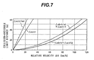
- Fig. 7 shows the deceleration-based collision-avoidable limit distance ⁇ xbrk, the lateral-motion-based collision-avoidable limit distance ⁇ xstr, the jerk-limited deceleration-based collision avoidable distance ⁇ xbrklmt, and the jerk-limited lateral-motion-based collision avoidable distance ⁇ xstrlmt shown in Fig. 5 .
- the lateral-motion-based collision-avoidable limit distance ⁇ xstr and the jerk-limited lateral-motion-based collision avoidable distance ⁇ xstrlmt are larger than the deceleration-based collision-avoidable limit distance ⁇ xbrk and jerk-limited deceleration-based collision avoidable distance ⁇ xbrklmt, respectively.
- the jerk-limited deceleration-based collision avoidable distance ⁇ xbrklmt equals the jerk-limited collision avoidable distance ⁇ xctl1
- the deceleration-based collision-avoidable limit distance ⁇ xbrk equals the collision-avoidable limit distance ⁇ xctl2.
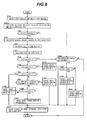
- Fig. 8 is a flow chart showing the operation of the forward collision avoidance assistance system according to the first embodiment.
- Fig. 8 shows calculations in the collision avoidance calculation unit 3 shown in Fig. 1 .
- the collision avoidance calculation unit 3 obtains host vehicle information and object information.
- the collision avoidance calculation unit 3 inputs the vehicle velocity V1_0, the vehicle longitudinal acceleration rate Gx1_0, the vehicle lateral acceleration rate Gy1_0, the steering angle ⁇ , and the master cylinder pressure Pm from the host vehicle information detection unit 1 shown in Fig. 1 .
- the collision avoidance calculation unit 3 may input the yaw rate r and the lateral moving velocity Vy1_0 in addition to the vehicle velocity V1_0, the vehicle longitudinal acceleration rate Gx1_0, the vehicle lateral acceleration rate Gy1_0, the steering angle ⁇ , and master cylinder pressure Pm.
- the collision avoidance calculation unit 3 inputs the relative distance between the host vehicle and the object ( ⁇ x), the object velocity V2_0, the object acceleration rate Gx2_0, the object width, and the offset amount ⁇ y from the object information detection unit 2 shown in Fig. 1 .
- Step S100 the collision avoidance calculation unit 3 calculates the relative velocity ⁇ V0 between the host vehicle and the object and the relative acceleration ⁇ Gx0 using Formulas (3) and (4), respectively.
- the collision avoidance calculation unit 3 also calculates the collision risk area VE2', the relative distance ⁇ x, and the offset amount Ay based on the object information.
- the collision risk area VE2' used by the forward collision avoidance assistance system according to the present embodiment is explained below with reference to Fig. 9 .
- Fig. 9 is a diagram showing a collision risk area used with the forward collision avoidance assistance system according to the first embodiment.
- the collision risk area VE2' is formed by adding a certain quantity to the width d2_0 of the object VE2.
- the object VE2 is laterally moving at a velocity Vy2_0 and the lateral acceleration Gy2_0, it is possible to make setting so as to enlarge the collision risk area VE2' in the traveling direction.
- a certain offset amount ⁇ y is added to the rear end position of the object VE2 to enlarge the collision risk area VE2' in the rear direction.
- the object VE2 has an acceleration
- the collision avoidance calculation unit 3 calculates the relative distance between the collision risk area VE2' and the host vehicle ( ⁇ x) and the offset amount between the center of the host vehicle and the center of the collision risk area VE2' ( ⁇ y).
- the collision avoidance calculation unit 3 may input the relative velocity ⁇ V0, the relative acceleration ⁇ Gx0, the relative distance Ax, and the offset amount Ay as object information.
- the collision avoidance calculation unit 3 determines whether or not an object is present depending on the possibility of collision between the host vehicle VE1 and the collision risk area VE2'. As a method for determining whether or not an object is present, if object information acquisition means does not detect any object, the collision avoidance calculation unit 3 determines that no object exists. Even if an object has been detected, if the relative velocity ⁇ V0 represented by Formula (3) is negative, the possibility of collision with an object is low and therefore the collision avoidance calculation unit 3 determines that no object exists.
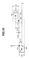
- Fig. 10 is a diagram showing a case where the offset amount ⁇ dR between the front left corner FLl and the rear right corner RR2 becomes negative in control with the forward collision avoidance assistance system according to the first embodiment.
- the collision avoidance calculation unit 3 determines that no object exists.
- the offset amount ⁇ dR between the front left corner FLl and the rear right corner RR2 represented by the Formula (1) becomes negative, as shown in Fig. 10 , the possibility of collision is low and therefore the collision avoidance calculation unit 3 determines that no object exists.
- the offset amount ⁇ dL between the front right corner FR1 and the rear right corner RL2 represented by Formula (2) becomes negative, the possibility of collision is low and therefore the collision avoidance calculation unit 3 determines that no object exists. If the vehicle velocity of the host vehicle is zero (stop state), the possibility of collision with an object is low and therefore the collision avoidance calculation unit 3 determines that no object exists.
- Step S200 of Fig. 8 if the collision avoidance calculation unit 3 determines that no object exists, processing proceeds to Step S1500; when it determines that there is an object, processing proceeds to Step S300.
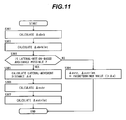
- Step S300 the collision avoidance calculation unit 3 calculates the deceleration-based collision avoidance limit ⁇ xbrk, the lateral-motion-based collision avoidance limit ⁇ xstr, the jerk-limited deceleration-based collision avoidable distance ⁇ xbrklmt, and the jerk-limited lateral-motion-based collision avoidable distance ⁇ xstrlmt.
- Fig. 11 is a flow chart showing calculations of the deceleration-based collision avoidance limit ⁇ xbrk, the lateral-motion-based collision avoidance limit ⁇ xstr, the jerk-limited deceleration-based collision avoidable distance ⁇ xbrklmt, and the jerk-limited lateral-motion-based collision avoidable distance ⁇ xstrlmt by the forward collision avoidance assistance system according to the first embodiment.
- Step S301 of Fig. 11 the collision avoidance calculation unit 3 calculates the deceleration-based collision avoidance limit ⁇ xbrk using the above-mentioned Formulas (3) to (10).
- the maximum possible deceleration - Gxmax on the road surface on which the host vehicle is traveling is assumed to be the maximum deceleration value that can be generated on the host vehicle on a dry road surface, i.e., the maximum possible deceleration -Gxmax on a dry road surface.
- the system includes maximum acceleration presumption means for presuming the maximum possible acceleration
- the maximum acceleration presumption means may be a method for presuming the maximum acceleration based on the road surface information obtained through communications between vehicles and between the road and the host vehicle, a method for presuming the maximum acceleration based on the operating state of the wiper of the host vehicle, or a method for presuming the maximum acceleration based on tire speed change of the host vehicle.
- the maximum acceleration presumption means can presume the road surface friction coefficient as road surface information based on tire speed change of the host vehicle, i.e., the brake force generated at each tire by the brake force control means.
- the deceleration-based collision avoidance limit ⁇ xbrk can be presumed with higher accuracy.
- presumption means may be a method for presuming the maximum acceleration based on the longitudinal acceleration, the brake torque, and the tire speed generated on the vehicle, or a method for presuming the maximum acceleration based on the lateral acceleration, the tire skid angle, and the tire speed generated on the vehicle.
- may be the absolute value of a value obtained by dividing the maximum deceleration -Gxmax by the time since deceleration is generated by the brake actuator used until the maximum deceleration -Gxmax is generated. Further, the maximum value of the possible longitudinal jerk by the brake actuator used may be used as the maximum longitudinal jerk
- Step S301 After calculation of the deceleration-based collision avoidance limit ⁇ xbrk in Step S301, processing proceeds to Step S302.
- Step S302 the collision avoidance calculation unit 3 calculates the jerk-limited deceleration-based collision avoidable distance ⁇ xbrklmt using Formulas (3) to (6) and Formulas (12) to (14).
- to be generated is preset to a value that applies neither intensive uncomfortable feeling nor a sudden posture change to a common driver.
- Step S302 After calculation of the jerk-limited deceleration-based collision avoidable distance ⁇ xbrklm in Step S302, processing proceeds to Step S303.
- Step S303 the collision avoidance calculation unit 3 determines whether or not lateral-motion-based collision avoidance is possible.
- the collision avoidance calculation unit 3 determines that lateral movement to the right with respect to the traveling direction is possible. If the left-hand side safe area ⁇ dLsafe of the collision risk area VE2' is larger than the width d1 of the host vehicle VE1, the collision avoidance calculation unit 3 determines that lateral movement to the left with respect to the traveling direction is possible.
- a certain offset amount ⁇ y is added to the right-hand side position of the host vehicle driving lane. It is possible to define the right-hand edge of an area judged to contain no object which may collide with the host vehicle as the right-hand edge Rsafe, the judgment being made using the object information acquisition means such as a CCD image pickup element or other image pickup devices, a millimeter-wave radar, a laser radar, etc. or communication means such as communications between the road and the host vehicle and between vehicles, navigation, etc.
- the object information acquisition means such as a CCD image pickup element or other image pickup devices, a millimeter-wave radar, a laser radar, etc.
- communication means such as communications between the road and the host vehicle and between vehicles, navigation, etc.
- a certain offset amount ⁇ y is added to the left-hand side position of the host vehicle driving lane. It is possible to define the left-hand edge of an area judged to contain no object which may collide with the host vehicle as the left-hand edge Lsafe, the judgment being made using the object information acquisition means such as a CCD image pickup element or other image pickup devices, a millimeter-wave radar, a laser radar, etc. or communication means such as communications between the road and the host vehicle and between vehicles, navigation, etc.
- the object information acquisition means such as a CCD image pickup element or other image pickup devices, a millimeter-wave radar, a laser radar, etc.
- communication means such as communications between the road and the host vehicle and between vehicles, navigation, etc.
- the collision avoidance calculation unit 3 determines that lateral-motion-based collision avoidance is impossible, and processing proceeds to Step S304.
- the collision avoidance calculation unit 3 determines that rightward lateral movement is possible. Further, if the left-hand side safe area ⁇ dLsafe is larger than the width d1 of the host vehicle and the right-hand side safe area ⁇ dRsafe is smaller than the width d1 of the host vehicle, the collision avoidance calculation unit 3 determines that leftward lateral movement is possible.
- the collision avoidance calculation unit 3 determines that both rightward and leftward lateral movements are possible, and processing proceeds to Step S305.
- the left-hand edge Lsafe and the right-hand edge Rsafe are limits the host vehicle can travel therebetween. If a left-hand edge Lsafe or a right-hand edge Rsafe exists in the host vehicle traveling direction, the left-hand edge Lsafe or the right-hand edge Rsafe is handled as the collision risk area VE2' in the host vehicle traveling direction.
- Step S304 the collision avoidance calculation unit 3 sets the lateral-motion-based collision avoidance limit ⁇ xstr and the jerk-limited lateral-motion-based collision avoidable distance ⁇ xstrlmt to a value larger than the relative distance between the object and the host vehicle ( ⁇ x), and terminates processing.
- Step S305 the collision avoidance calculation unit 3 calculates a required lateral-movement distance ⁇ d. If rightward lateral movement is possible, the offset amount ⁇ dR obtained by the Formula (1) is set as the required lateral-movement distance ⁇ d; if leftward lateral movement is possible, the offset amount ⁇ dL obtained by the Formula (2) is set as the required lateral-movement distance ⁇ d. Further, if both rightward and leftward lateral movements are possible, the offset amount ⁇ dR or the offset amount ⁇ dL, whichever smaller, is set as the required lateral-movement distance ⁇ d.
- the required lateral-movement distance ⁇ d may be determined based on a magnitude relation between the offset amount ⁇ dR and the offset amount ⁇ dL as well as a magnitude relation between the left-hand side safe area ⁇ dLsafe and the right-hand side safe area ⁇ dRsafe. For example, if the difference between the offset amount ⁇ dR and the offset amount ⁇ dL is equal to or smaller than a certain threshold value, and the right-hand side safe area ⁇ dRsafe is larger than the left-hand side safe area ⁇ dLsafe, the offset amount ⁇ dR may be used as the required lateral-movement distance ⁇ d.
- the offset amount ⁇ dL may be used as the required lateral-movement distance ⁇ d.
- Step S306 After calculation of the required lateral-movement distance ⁇ d in Step S306, processing proceeds to Step S306.
- Step S306 the collision avoidance calculation unit 3 calculates the lateral-motion-based collision-avoidable limit distance ⁇ xstr.
- the collision avoidance calculation unit 3 calculates the time ⁇ tstr taken for movement with reference to Fig. 4 based on the required lateral-movement distance ⁇ d, and calculates the lateral-motion-based collision-avoidable limit distance ⁇ xstr using Formula (11) based on the time ⁇ tstr taken for movement.
- Step S306 After calculation of the lateral-motion-based collision-avoidable limit distance ⁇ xstr in Step S306, processing proceeds to Step S307.
- Step S307 the collision avoidance calculation unit 3 calculates the jerk-limited lateral-motion-based collision avoidable distance ⁇ xstrlmt.
- the collision avoidance calculation unit 3 calculates the time ⁇ tstrlmt taken for movement with reference to Fig. 3 from the required lateral-movement distance ⁇ d, and calculates the jerk-limited lateral-motion-based collision avoidable distance ⁇ xstrlmt using Formula (16) from the time ⁇ tstrlmt taken for movement.
- to be generated is preset to a value that applies neither intensive uncomfortable feeling nor a sudden posture change to a common driver.
- the collision avoidance calculation unit 3 After calculation of the jerk-limited lateral-motion-based collision avoidable distance ⁇ xstrlmt in Step S307, the collision avoidance calculation unit 3 terminates processing.
- Step S400 the collision avoidance calculation unit 3 calculates the jerk-limited collision avoidable distance ⁇ xctl1 and the collision-avoidable limit distance ⁇ xctl2.
- FIG. 5 nine regions are created in terms of the deceleration-based collision-avoidable limit distance ⁇ xbrk, the lateral-motion-based collision-avoidable limit distance ⁇ xstr, the jerk-limited deceleration-based collision avoidable distance ⁇ xbrklmt, and the jerk-limited lateral-motion-based collision avoidable distance ⁇ xstrlmt.
- a boundary between the regions A1 to A5 and the regions A6 to A8 is defined as the jerk-limited collision avoidable distance ⁇ xctl1 at which a warning for collision avoidance and deceleration control for collision avoidance are started.
- the region A9 is a region where collision cannot be avoided.
- a boundary between the regions A6 to A8 and the region A9 is defined as the collision-avoidable limit distance ⁇ xctl2.
- the jerk-limited collision avoidable distance ⁇ xctl1 is either the jerk-limited deceleration-based collision avoidable distance ⁇ xbrklmt or the jerk-limited lateral-motion-based collision avoidable distance ⁇ xstrlmt, whichever smaller.
- the collision-avoidable limit distance ⁇ xctl2 is either the deceleration-based collision-avoidable limit distance ⁇ xbrk or the lateral-motion-based collision-avoidable limit distance ⁇ xstr, whichever smaller.
- the deceleration-based collision-avoidable limit distance ⁇ xbrk the deceleration-based collision-avoidable limit distance ⁇ xbrk, the lateral-motion-based collision-avoidable limit distance ⁇ xstr, the jerk-limited deceleration-based collision avoidable distance ⁇ xbrklmt, and the jerk-limited lateral-motion-based collision avoidable distance ⁇ xstrlmt are given as shown in Fig. 7 .
- Fig. 7 As shown in Fig.
- the jerk-limited deceleration-based collision avoidable distance ⁇ xbrklmt equals the jerk-limited collision avoidable distance ⁇ xctl1
- the deceleration-based collision-avoidable limit distance ⁇ xbrk equals the collision-avoidable limit distance ⁇ xctl2.
- Step S303 the jerk-limited deceleration-based collision avoidable distance ⁇ xbrklmt, the jerk-limited deceleration-based collision avoidable distance ⁇ xbrklmt, the deceleration-based collision-avoidable limit distance ⁇ xbrk, and the lateral-motion-based collision-avoidable limit distance ⁇ xstr are given as shown in Fig. 6 . As shown in Fig.
- the jerk-limited deceleration-based collision avoidable distance ⁇ xbrklmt equals the jerk-limited collision avoidable distance ⁇ xctl1
- the deceleration-based collision-avoidable limit distance ⁇ xbrk equals the collision-avoidable limit distance ⁇ xctl2
- the jerk-limited lateral-motion-based collision avoidable distance ⁇ xstrlmt equals the jerk-limited collision avoidable distance ⁇ xctl1
- the lateral-motion-based collision-avoidable limit distance ⁇ xstr equals the collision-avoidable limit distance ⁇ xctl2.
- Step S500 After calculation of the jerk-limited collision avoidable distance ⁇ xctl1 and the collision-avoidable limit distance ⁇ xctl2, processing proceeds to Step S500.
- Step S500 the collision avoidance calculation unit 3 calculates a risk of collision.
- the collision avoidance calculation unit 3 calculates a risk of collision based on the relative distance ⁇ x, the relative velocity ⁇ V, the jerk-limited collision avoidable distance ⁇ xctl1, and the collision-avoidable limit distance ⁇ xctl2.
- the collision avoidance calculation unit 3 performs calculation as follows: the distance over which the relative distance Ax equals the jerk-limited collision avoidable distance ⁇ xctl1 is set to "0"; the distance is set to "0" if the relative distance Ax is larger than the jerk-limited collision avoidable distance ⁇ xctl1, increased as the relative distance Ax becomes smaller than the jerk-limited collision avoidable distance ⁇ xctl1, and set to "100" when the collision-avoidable limit distance ⁇ xctl2 is reached.
- the collision avoidance calculation unit 3 may calculate a risk of collision based on a time until the collision avoidance limit is reached, the time being obtained by dividing the difference between the relative distance ⁇ x and the collision-avoidable limit distance ⁇ xctl2 by the relative velocity ⁇ V. After calculation of the risk of collision, processing proceeds to Step S600.
- Step S600 the collision avoidance calculation unit 3 compares the relative distance ⁇ x with the jerk-limited collision avoidable distance ⁇ xctl1.
- Step S600 if the relative distance ⁇ x is larger than the jerk-limited collision avoidable distance ⁇ xctl1, the collision avoidance calculation unit 3 determines that the collision-avoidable limit distance is in any of the regions A1 to A5, and processing proceeds to Step S1500.
- Step S1500 the collision avoidance calculation unit 3 determines whether or not the host vehicle is under deceleration control. If deceleration control is not performed as a result of the last calculation, the collision avoidance calculation unit 3 determines that the host vehicle is not under deceleration control. Even if the host vehicle is under deceleration control as a result of the last calculation, if the brake torque generated by driver's braking operation is almost equal to or larger than the brake torque due to deceleration control, the collision avoidance calculation unit 3 terminates deceleration control and determines that the host vehicle is not under deceleration control.
- Step S1500 if the collision avoidance calculation unit 3 determines that the host vehicle is not under deceleration control by the forward collision avoidance assistance system, processing is terminated; if it determines that the host vehicle is under deceleration, processing proceeds to Step S1600.
- Step S1600 the collision avoidance calculation unit 3 determines whether or not the host vehicle is in the stop state. If the vehicle velocity of the host vehicle is zero, the collision avoidance calculation unit 3 determines that the host vehicle is in the stop state, and processing proceeds to Step S1700. If the vehicle velocity of the host vehicle is not zero and accordingly the host vehicle is judged to be not in the stop state, that is, in a traveling state, processing proceeds to Step S1800.
- the collision avoidance calculation unit 3 performs target brake torque calculation and warning operation in relation to the vehicle in the stop state due to deceleration control as target brake torque/warning operation 5 in Step S1700. Brake torque necessary to maintain the vehicle stop state is defined as the target brake torque. Then, the collision avoidance calculation unit 3 calculates a drive command for the warning device to prompt driver's braking operation.
- the collision avoidance calculation unit 3 performs target brake torque calculation and warning operation in relation to a state where no object exists ahead of the host vehicle traveling under deceleration control or a state where the relative distance ⁇ x is larger than the jerk-limited collision avoidable distance ⁇ xctl1 as target brake torque/warning operation 6 in Step S1800. This applies to a state where an object ahead of the host vehicle accelerates during deceleration control resulting in an increased relative distance or a state where the object ahead of the host vehicle deviates from the course of the host vehicle through lateral movement.
- the collision avoidance calculation unit 3 calculates a target longitudinal acceleration based on the longitudinal acceleration due to deceleration control and the driver-requested longitudinal acceleration presumed from the state of driver's braking operation, and calculates target brake torque of each tire based on the target longitudinal acceleration.
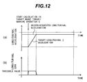
- Figs. 12A and 12B are graphs showing calculation of a target longitudinal acceleration by the forward collision avoidance assistance system according to the first embodiment.
- Fig. 12A shows the longitudinal acceleration
- Fig. 12B the longitudinal jerk.
- the horizontal axis of Figs. 12A and 12B denotes time t.
- the absolute value of the longitudinal jerk generated on the vehicle is maintained not larger than a certain threshold value, as shown in Fig. 12B .
- the acceleration is changed with the target longitudinal acceleration in relation to the longitudinal jerk not larger than the threshold value so that the target longitudinal acceleration converges to the driver-requested longitudinal acceleration.
- target longitudinal acceleration change may be subjected to filter processing to be used as the target longitudinal acceleration.
- the collision avoidance calculation unit 3 calculates the target brake torque based on the target longitudinal acceleration obtained in this way. It is also possible to calculate the target brake torque based on brake torque generated at each tire and the driver-requested brake torque calculated from the state of driver's braking operation state, without calculating the target longitudinal acceleration. In this case, it is possible to calculate the target brake torque so as to converge to the driver-requested brake torque while maintaining brake torque change of each tire not larger than a certain threshold value.
- the collision avoidance calculation unit 3 calculates a drive command for the warning device so as to notify the driver of the fact that the possibility of collision has become low. As a method for notification, it is possible to terminate the warning from the warning device to notify the driver of the fact that the possibility of collision has become low.
- Step S600 if the relative distance Ax is smaller than the jerk-limited collision avoidable distance ⁇ xctl1, the collision avoidance calculation unit 3 determines that the collision-avoidable limit distance is in any of the regions A6 to A9 and that a warning for collision avoidance support and deceleration control is necessary, and processing proceeds to Step S700.
- Step S700 the collision avoidance calculation unit 3 compares the relative distance Ax with the collision-avoidable limit distance ⁇ xctl2.
- Step S700 if the relative distance Ax is smaller than the collision-avoidable limit distance ⁇ xctl2, the collision avoidance calculation unit 3 determines that the collision-avoidable limit distance is in the region A9, and processing proceeds to Step S1100.
- Step S1100 as target brake torque/warning operation 1, the collision avoidance calculation unit 3 performs target brake torque calculation and warning operation in relation to the region A9.
- the collision avoidance calculation unit 3 sets the target longitudinal acceleration to -
- the collision avoidance calculation unit 3 calculates a drive command for the warning device so as to notify the driver of the fact that the possibility of collision is very high.
- the notification for the driver may include information for prompting driver's brake pedal operation.
- Step S1700 Upon completion of target brake torque/warning operation 5 in Step S1700, processing proceeds to Step S1900.
- Step S700 if the relative distance ⁇ x is equal to or larger than the collision-avoidable limit distance ⁇ xctl2, the collision avoidance calculation unit 3 determines that the collision-avoidable limit distance is in any of the regions A6 to A8, and processing proceeds to Step S800.
- Step S800 the collision avoidance calculation unit 3 compares the relative distance ⁇ x with the lateral-motion-based collision-avoidable limit distance ⁇ xstr.
- Step S800 if the relative distance ⁇ x is smaller than the lateral-motion-based collision-avoidable limit distance ⁇ xstr, the collision avoidance calculation unit 3 determines that the collision-avoidable limit distance is in the region A8, and processing proceeds to Step S1200.
- Step S1200 as target brake torque/warning operation 2, the collision avoidance calculation unit 3 performs target brake torque calculation necessary to perform deceleration-based collision avoidance, and warning operation.
- Figs. 13A, 13B, and 13C are graphs showing control with the upper-limit longitudinal jerk
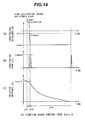
- Figs. 14A, 14B, and 14C are graphs showing control with the maximum longitudinal jerk
- Fig. 13A shows the longitudinal acceleration
- Fig. 13B shows the longitudinal jerk
- Fig. 13C the relative distance Ax
- Fig. 14A shows the longitudinal acceleration
- Fig. 14B shows the longitudinal jerk
- Fig. 14C the relative distance ⁇ x.
- the horizontal axis of Figs. 13A to 13C and 14A to 14C denotes time t.
- the collision avoidance calculation unit 3 starts deceleration control when the relative distance ⁇ x becomes equal to the jerk-limited collision avoidable distance ⁇ xctl1.
- the collision avoidance calculation unit 3 determines the longitudinal jerk
- the collision avoidance calculation unit 3 calculates the target longitudinal acceleration based on the determined longitudinal jerk
- a relative velocity ⁇ V range where the jerk-limited deceleration-based collision avoidable distance ⁇ xbrklmt equals the jerk-limited collision avoidable distance ⁇ xctl1 i.e., in a case where the jerk-limited deceleration-based collision avoidable distance ⁇ xbrklmt is smaller the jerk-limited lateral-motion-based collision avoidable distance ⁇ xstrlmt, if the maximum possible acceleration on the road surface does not change with a road surface change, a maximum acceleration
- Fig. 14C shows a case where deceleration control is started when the relative distance Ax is equal to the collision-avoidable limit distance ⁇ xctl2, and deceleration control is performed with the maximum deceleration -
- the collision avoidance calculation unit 3 calculates a drive command for the warning device so as to notify the driver of the fact that there is a possibility of collision with an object and that deceleration-based collision avoidance control is to be performed, through the warning device at the start of deceleration control. Further, the notification for the driver may include information for prompting driver's brake pedal operation.
- Step S1200 Upon completion of target brake torque/warning operation 2 in Step S1200, processing proceeds to Step S1900.
- Step S800 if the relative distance ⁇ x is equal to or larger than the lateral-motion-based collision-avoidable limit distance ⁇ xstr, the collision avoidance calculation unit 3 determines that the collision-avoidable limit distance is in either the region A6 or A7, and processing proceeds to Step S900.
- Step S900 the collision avoidance calculation unit 3 determines whether or not avoidance steering operation is performed by the driver.
- Step S900 the collision avoidance calculation unit 3 determines whether or not avoidance steering operation is performed based on the steering angle and the steering angular velocity. If steering operation toward a direction judged to enable collision avoidance has been performed in Step S303, and if the steering angle is equal to or larger than a certain threshold value or the steering angular velocity has a tendency to increase toward the direction judged to enable collision avoidance, the collision avoidance calculation unit 3 determines that avoidance steering operation is performed. For example, in the Step S303, the collision avoidance calculation unit 3 determines that rightward collision avoidance is possible.
- the collision avoidance calculation unit 3 determines that rightward avoidance steering is performed.
- the collision avoidance calculation unit 3 calculates the lateral acceleration necessary for lateral-motion-based collision avoidance and then determines the steering angle threshold value based on a steering angle necessary to generate the lateral acceleration.
- Step S900 if the collision avoidance calculation unit 3 determines that avoidance steering is performed, processing proceeds to Step S1300.
- Step S1300 as target brake torque/warning operation 3, the collision avoidance calculation unit 3 performs target brake torque calculation and warning operation in relation to a case where avoidance operation is performed by the driver in either the region A6 or A7.
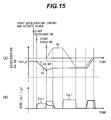
- Figs. 15A and 15B are graphs showing control in target brake torque/warning operation 3 by the forward collision avoidance assistance system according to the first embodiment.
- Fig. 15A shows the longitudinal acceleration Gx and the lateral acceleration Gy
- Fig. 15B the longitudinal jerk
- the horizontal axis of Figs. 15A and 15B denotes time t.
- the collision avoidance calculation unit 3 calculates the target longitudinal acceleration so that the longitudinal acceleration Gx may fluctuate in response to driver's steering operation.
- the control method is changed depending on the deceleration generated at the start of steering operation. For example, if the deceleration at the start of steering operation is large, the deceleration is decreased based on the steering speed. If the deceleration at the start of steering operation is small or zero, the deceleration is maintained unchanged or fluctuated based on the steering speed.
- the collision avoidance calculation unit 3 calculates the target brake torque of each tire so as to generate the target longitudinal acceleration.
- the collision avoidance calculation unit 3 calculates the target brake torque of each tire so as to generate a moment for swirling the vehicle toward a direction in which lateral-motion-based collision avoidance is possible.
- the collision avoidance calculation unit 3 calculates a drive command for the warning device so as to notify the driver of the fact that there is a possibility of collision with an object and that deceleration-based collision avoidance control is to be performed, and then notify the driver of the steering direction, through the warning device at the start of deceleration control.
- the content of the warning regarding the steering direction and the amount of steering may be changed in relation to the amount of steering by the driver. For example, if the amount of steering by the driver is not sufficient for object avoidance, it is possible to give a warning so as to increase the amount of steering.
- Step S900 if the collision avoidance calculation unit 3 determines that avoidance steering is not performed, processing proceeds to Step S1000.
- Step S1000 the collision avoidance calculation unit 3 compares the relative distance Ax with the deceleration-based collision-avoidable limit distance ⁇ xbrk.
- Step S1000 if the relative distance ⁇ x is equal to or larger than the deceleration-based collision-avoidable limit distance ⁇ xbrk, the collision avoidance calculation unit 3 determines that the collision-avoidable limit distance is in the region A6, and processing proceeds to Step S1200. Subsequently in Step S1200, the collision avoidance calculation unit 3 performs the above-mentioned calculation.
- Step S800 if the relative distance Ax is smaller than the deceleration-based collision-avoidable limit distance ⁇ xbrk, the collision avoidance calculation unit 3 determines that the collision-avoidable limit distance is in the region A7, and processing proceeds to Step S1400.
- Step S1400 as target brake torque/warning operation 4, the collision avoidance calculation unit 3 performs target brake torque calculation and warning operation for the region A7.
- the collision avoidance calculation unit 3 instructs the driver to perform steering operation toward a direction in which lateral-motion-based collision avoidance is possible.
- the collision avoidance calculation unit 3 generates a moment for swirling the vehicle toward a direction in which lateral-motion-based collision avoidance is possible by means of the brake torque of each tire.
- the collision avoidance calculation unit 3 calculates a required moment as a target moment, and calculates the target brake torque of each tire so as to generate the target longitudinal acceleration and the target moment.
- the collision avoidance calculation unit 3 calculates a drive command for the warning device so as to notify the driver of the fact that there is a possibility of collision with an object and that deceleration-based collision avoidance control is to be performed, and then notify the driver of the steering direction, through the warning device at the start of deceleration control. In this case, it is possible to notify the driver of the required amount of steering in addition to the steering direction.
- Step S1400 Upon completion of target brake torque/warning operation 4 in Step S1400, processing proceeds to Step S1900.
- Step S1900 the collision avoidance calculation unit 3 performs drive control of the brake actuator so as to attain the target brake torque and drive control of the alarm unit so as to attain the above-mentioned warning, and turns on the tail-light in response to the drive of the brake actuator.
- the collision avoidance calculation unit 3 performs drive control of the brake actuator using the brake torque generated by driver's braking operation or the brake torque calculated in Steps S1100 to S1400, whichever larger, as the target brake torque. If a target moment is calculated in Steps S1300 and S1400 and brake torque is calculated so as to generate the target moment, the collision avoidance calculation unit 3 gives priority to the brake torque calculated in Steps S1300 to S1400 and performs drive control of the brake actuator as the target brake torque.
- the brake actuator may be either a brake system which generates brake torque by pushing a brake pad to a brake disc attached on each tire or a method for generating brake torque through regenerative drive of a motor.
- the brake actuator for generating brake torque at each tire is not limited thereto.
- the alarm unit may be a warning device which auditorily gives a warning or a warning device which visually gives a warning. Further, the warning device may be combined with a warning device which tactually gives a warning.
- warning method it is possible to visually display or auditorily announce a result of calculations performed in above-mentioned target brake torque/warning operations 1 to 6, or use a combination of visual display and auditory announcement. For example, it is possible to visually display a warning and generate an alarm sound to inform the driver of the warning.
- warning device it is also possible to change control variables of the warning device in relation to the risk of collision.
- a warning device which auditorily gives a warning it is possible to change the alarm sound volume in relation to the risk of collision, that is, the larger the risk of collision, the larger becomes the alarm sound volume.
- a warning device which visually gives a warning it is possible to change the display image in relation to the risk of collision.
- the warning device which tactually gives a warning it is possible to change the interval and amplitude of vibration in relation to the risk of collision.
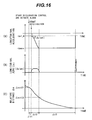
- Figs. 16A, 16B, and 16C are graphs showing another example of the maximum value of the longitudinal jerk
- Fig. 16A shows the longitudinal acceleration Gx
- Fig. 16B shows the longitudinal jerk
- Fig. 16C the relative distance Ax.
- the horizontal axis of Figs. 16A to 16C denotes time t.
- ⁇ t2 changes with the shape of the longitudinal jerk
- deceleration-based collision-avoidable limit distance ⁇ xbrk the lateral-motion-based collision-avoidable limit distance ⁇ xstr
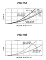
- the jerk-limited deceleration-based collision avoidable distance ⁇ xbrklmt the jerk-limited lateral-motion-based collision avoidable distance ⁇ xstrlmt used in the forward collision avoidance assistance system according to the present embodiment are explained below with reference to Fig. 17 .
- Figs. 17A and 17B are graphs showing another example of the deceleration-based collision-avoidable limit distance ⁇ xbrk and the jerk-limited deceleration-based collision avoidable distance ⁇ xbrklmt used by the forward collision avoidance assistance system according to the first embodiment.
- the collision avoidance calculation unit 3 calculates necessary target brake torque of each tire so that the vehicle decelerates with the maximum possible acceleration -
- the collision avoidance calculation unit 3 sets the deceleration with the upper-limit longitudinal jerk
- the collision avoidance calculation unit 3 instructs the driver to perform steering toward a direction in which lateral-motion-based collision avoidance is possible. At the same time, the collision avoidance calculation unit 3 generates a moment for swirling the vehicle toward a direction in which lateral-motion-based collision avoidance is possible by means of the brake torque of each tire.
- the collision avoidance calculation unit 3 sets the deceleration with the upper-limit longitudinal jerk
- the present embodiment supports collision avoidance suitable for each of the nine regions to attain the reduction of driver's uncomfortable feeling and the improvement of the drivability while ensuring the collision avoidance performance at the time of avoidance of collision with an object.
- Fig. 18 is a system block diagram showing the configuration of the forward collision avoidance assistance system according to the second embodiment.
- the same reference numerals as in Fig. 1 denote identical parts.
- the forward collision avoidance assistance system of the present embodiment is mounted on a vehicle, the system comprising: a host vehicle information detection unit 1A for obtaining the host vehicle movement state and driver's operation variables; an object information detection unit 2A for detecting an object existing in the host vehicle traveling direction; a collision avoidance calculation unit 3A for calculating a risk of collision between the host vehicle and the object and giving control commands to an alarm unit 4, a brake actuator 5, a tail-light 6, and electronic control throttle actuator 7; an alarm unit 4 for giving a warning to the driver based on a command from the collision avoidance calculation unit 3; a brake actuator 5 for generating brake force at each tire; a tail-light 6 for indicating the deceleration of the host vehicle to a following vehicle; and an electronic control throttle actuator 7 for controlling the engine torque, as shown in Fig. 18 .
- the present embodiment is provided with the electronic control throttle actuator 7 in addition to the configuration shown in Fig. 1 .
- the object information detection unit 2, the alarm unit 4, the brake actuator 5, and the tail-light 6 are the same as in Fig. 1 .
- the host vehicle information detection unit 1A includes the amount of accelerator pedal stroke, a driver's accelerator pedal operation variable, detected as an electric signal by a detector in addition to the host vehicle information detection unit 1 of Fig. 1 .
- the electronic control throttle actuator 7 performs predetermined calculation processing for the amount of accelerator pedal stroke and performs open/close control of the throttle as a throttle valve control apparatus for the on-board engine. This operation replaces direct throttle valve opening adjustment operation through driver's accelerator pedal operation.
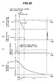
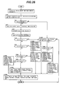
- Fig. 19 is a flow chart showing the operation of the forward collision avoidance assistance system according to the second embodiment.
- Steps S000 to S1000 and S1600 are the same as Steps S000 to S1000 and S1600 of Fig. 8 .
- Step S1100A to S1400A the collision avoidance calculation unit 3A performs target throttle valve opening calculation in addition to target brake torque/warning operations 1 to 4 described in Steps S1100 to S1400 of Fig. 8 .
- Figs. 20A, 20B, 20C, and 20D are graphs showing calculation of a target throttle valve opening in the forward collision avoidance assistance system according to the second embodiment.
- Fig. 20A shows the longitudinal acceleration
- Fig. 20B shows the longitudinal jerk
- Fig. 20C shows the throttle valve opening
- Fig. 20D the relative distance ⁇ x.
- the horizontal axis of Figs. 20A to 20D denotes time t.
- the dashed line shows the throttle valve opening in relation to the driver's accelerator pedal operation variable
- the solid line shows the throttle valve opening calculated by the collision avoidance calculation unit 3A of the present embodiment.
- the collision avoidance calculation unit 3A calculates the target throttle valve opening so that, after the start of deceleration control, the throttle valve opening in a state where the driver does not depress the accelerator, i.e., accelerator-off state is attained regardless of driver's accelerator pedal operation.
- deceleration control can be performed without engine torque increase even if the amount of accelerator pedal depression by the driver changes with the longitudinal acceleration generated.
- Step S1500A of Fig. 19 the collision avoidance calculation unit 3A determines whether or not the host vehicle is under deceleration control. If deceleration control is not performed as a result of last calculation processing, the collision avoidance calculation unit 3A determines that the host vehicle is not under deceleration control.
- the collision avoidance calculation unit 3A terminates deceleration control and determines that the host vehicle is not under deceleration control.
- Step S1700A the collision avoidance calculation unit 3A performs target throttle valve opening calculation in addition to target brake torque/warning operation 5 described in Step S1700 of Fig. 8 .
- the collision avoidance calculation unit 3A calculates the target throttle valve opening so that the throttle valve opening in a state where the driver does not depress the accelerator, i.e., accelerator-off state is attained regardless of driver's accelerator pedal operation.
- Step S1800A as target brake torque/target throttle valve opening/warning operation 6, the collision avoidance calculation unit 3A performs target brake torque and target throttle valve opening calculations, and warning operation in relation to a state where no object exists ahead of the vehicle traveling under deceleration control or a state where the relative distance ⁇ x is larger than the jerk-limited collision avoidable distance ⁇ xctl1. This applies to a state where an object ahead of the host vehicle accelerates during deceleration control resulting in an increased relative distance or a state where the object ahead of the host vehicle deviates from the course of the host vehicle through lateral movement.
- the collision avoidance calculation unit 3A calculates the target longitudinal acceleration based on the longitudinal acceleration due to deceleration control and the driver-requested longitudinal acceleration presumed from the states of driver's braking and accelerator pedal operations, and calculates the target brake torque of each tire and the target throttle valve opening based on the target longitudinal acceleration.
- Figs. 21A and 21B are graphs showing calculations of the target longitudinal acceleration in the forward collision avoidance assistance system according to the second embodiment.
- Fig. 21A shows the longitudinal acceleration
- Fig. 21B the longitudinal jerk.
- the horizontal axis of Fig. 21 denotes time t.
- the target longitudinal acceleration is changed to converge the target longitudinal acceleration to the driver-requested longitudinal acceleration as shown in Fig. 21A while maintaining the absolute value of the longitudinal jerk generated on the vehicle not larger than a certain threshold value as shown in Fig. 21B .
- target longitudinal acceleration change may be subjected to filter processing to be used as the target longitudinal acceleration. It is also possible to calculate the target brake torque based on brake torque generated at each tire and the driver-requested brake torque calculated from driver's braking operation state, without calculating the target longitudinal acceleration, and calculate the target throttle valve opening based on the driver-requested brake torque calculated from the state of driver's accelerator pedal operation.
- the target brake torque so as to converge to the driver-requested brake torque while maintaining brake torque change of each tire not larger than a certain threshold value; and then, after the target brake torque has converged to the driver-requested brake torque, calculate the target throttle valve opening so as to converge to the driver-requested throttle valve opening while maintaining engine torque change accompanying a throttle valve opening change not larger than a certain threshold value, thus converging the target throttle valve opening to the driver-requested throttle valve opening.
- the collision avoidance calculation unit 3A calculates a drive command of the warning device to notify the driver of the fact that the possibility of collision has become low. As a method for notification, it is possible to terminate the warning from the warning device to notify the driver of the fact that the possibility of collision has become low.
- Step S1900A in the same way as in Step S1900 of Fig. 8 , the collision avoidance calculation unit 3A performs drive control of the brake actuator and the alarm unit, and turns on the tail-light in response to the drive of the brake actuator. Further, the collision avoidance calculation unit 3A performs drive control of the electronic control throttle actuator so as to attain the target throttle valve opening.
- the present embodiment supports collision avoidance suitable for each of the nine regions to attain the reduction of driver's uncomfortable feeling and the improvement of the drivability while ensuring the collision avoidance performance at the time of avoidance of collision with an object.
- deceleration control can be performed without engine torque increase even if the amount of accelerator pedal depression by the driver changes with the longitudinal acceleration generated.
- Fig. 22 is a system block diagram showing the configuration of the forward collision avoidance assistance system according to the third embodiment.
- the same reference numerals as in Fig. 1 denote identical parts.
- the forward collision avoidance assistance system of the present embodiment is mounted on a vehicle, the system comprising: a host vehicle information detection unit 1A for obtaining the host vehicle movement state and driver's operation variables; an object information detection unit 2A for detecting an object existing in the host vehicle traveling direction; a collision avoidance calculation unit 3B for calculating a risk of collision between the host vehicle and the object and giving control commands to an alarm unit 4, a brake actuator 5, a tail-light 6, an electronic control throttle actuator 7, and a steering actuator 8; an alarm unit 4 for giving a warning to the driver based on a command from the collision avoidance calculation unit 3B; a brake actuator 5 for generating brake force at each tire; a tail-light 6 for indicating the deceleration of the host vehicle to a following vehicle; an electronic control throttle actuator 7 for controlling the engine torque; a steering actuator 8 for generating lateral acceleration on the vehicle; and a road surface information detection unit 9 for obtaining the road shape such as the road surface curvature in the host vehicle traveling direction, as shown in Fig. 22
- the host vehicle information detection unit 1A, the object information detection unit 2, the alarm unit 4, the brake actuator 5, the tail-light 6, and the electronic control throttle actuator 7 are the same as in the embodiment of Fig. 18 .
- the steering actuator 8 changes the skid angle of each tire to generate the lateral acceleration on the vehicle.
- the steering actuator 8 may be a front-wheel steering mechanism which changes the skid angle of the front tires of the vehicle, a rear-wheel steering mechanism which changes the skid angle of the rear tires of the vehicle, or a four-wheel steering mechanism which changes the skid angle of all tires.
- the steering mechanism is a steering-by-wire mechanism which converts the steering angle generated by driver's steering wheel operation to an electric signal, and performs drive control of the actuator so as to change the skid angle of each tire based on the electric signal.
- the steering wheel is not mechanically connected with the steering mechanism of each tire.
- the road surface information detection unit 9 inputs the road shape on which the host vehicle will travel in the future.
- the road surface information detection unit 9 may input information about the lane width of the host vehicle driving lane and the lane width of lanes adjacent to the host vehicle driving lane.
- As a method for obtaining the road shape information it is possible to use a GPS and road surface map information or calculate the road shape from images of the road surface ahead of the host vehicle imaged using an image pickup device such as a CCD image pickup element. Further, the road surface information detection unit 9 may input information about the road surface friction coefficient.
- the collision avoidance calculation unit 3B will be explained later with reference to Fig. 23 .
- Collision avoidance support control through steering control by the forward collision avoidance assistance system according to the third embodiment is explained below with reference to Figs. 23 and 24 .
- Fig. 23 is a flow chart showing the operation of the forward collision avoidance assistance system according to the third embodiment.
- Steps S100 to S700 and S1600 are the same as Steps S100 to S700 and S1600 of Fig. 8 .
- the collision avoidance calculation unit 3B obtains host vehicle information, object information, and road surface information.
- the collision avoidance calculation unit 3B inputs the vehicle velocity V1_0, the vehicle longitudinal acceleration rate Gx1_0, the vehicle lateral acceleration rate Gy1 _ 0, the steering angle ⁇ , the master cylinder pressure Pm, and the amount of accelerator pedal stroke from the host vehicle information detection unit 1A.
- the collision avoidance calculation unit 3B may input the yaw rate r and the lateral moving velocity Vy1_0.
- the collision avoidance calculation unit 3B inputs the relative distance ⁇ x, the relative velocity ⁇ V, and the relative acceleration ⁇ Gx with respect to the host vehicle, the collision risk area width d2, and the collision risk area offset amount ⁇ y from the object information detection unit 2.
- the collision avoidance calculation unit 3B inputs the road shape on which the host vehicle will travel in the future from the road surface information detection unit 9. Further, the collision avoidance calculation unit 3B may input the information about the lane width of the host vehicle driving lane and the lane width of lanes adjacent to the host vehicle driving lane. Further, the collision avoidance calculation unit 3B may input information about the road surface friction coefficient.
- Step S1100B of Fig. 23 as target brake torque/target throttle valve opening/target steering angle/warning operation 1, the collision avoidance calculation unit 3B performs target brake torque, target throttle valve opening, and target steering angle calculations, and warning operation in relation to the region A9.
- the collision avoidance calculation unit 3B sets the target longitudinal acceleration to -
- the collision avoidance calculation unit 3B calculates the target throttle valve opening so that, after the start of deceleration control, the throttle valve opening in a state where the driver does not depress the accelerator, i.e., accelerator-off state is attained regardless of driver's accelerator pedal operation.
- the collision avoidance calculation unit 3B calculates a drive command for the warning device so as to notify the driver of the fact that the possibility of collision is very high.
- the notification for the driver may include information for prompting driver's brake pedal operation.
- Step S800B the collision avoidance calculation unit 3B compares the relative distance ⁇ x with the deceleration-based collision-avoidable limit distance ⁇ xbrk.
- Step S800B if the relative distance ⁇ x is smaller than the deceleration-based collision-avoidable limit distance ⁇ xbrk, the collision avoidance calculation unit 3B determines that the collision-avoidable limit distance is in the region A7, and processing proceeds to Step S1400B.
- Step S1400B as target brake torque/target throttle valve opening/target steering angle/warning operation 4, the collision avoidance calculation unit 3B performs target brake torque, target throttle valve opening, and target steering angle calculations, and warning operation in relation to the region A7 of Fig. 5 .
- the collision avoidance calculation unit 3B calculates the target lateral acceleration necessary for collision avoidance, and calculates the target steering angle so as to generate the target lateral acceleration.
- Figs. 24A and 24 are graphs showing calculation of a target lateral acceleration in the forward collision avoidance assistance system according to the third embodiment.
- Fig. 24A shows the lateral acceleration
- Fig. 24B the lateral jerk.
- the horizontal axis of Fig. 24 denotes time t.
- generated by the lateral movement is equal to or smaller than the upper-limit lateral jerk
- generated can be maintained low.
- calculated here applies to a case where the maximum possible acceleration on the road surface does not change with a road surface change, a presumption error of the maximum acceleration
- Step S1400B the collision avoidance calculation unit 3B calculates the target brake torque and the target throttle valve opening so as to attain the target lateral acceleration. For example, if the driver is performing strong braking operation, it is possible to calculate the target brake torque so as to decrease the brake torque in relation to the lateral acceleration to be generated. It is also possible to calculate the target brake torque and the target throttle valve opening in relation to the lateral jerk to be generated.
- the collision avoidance calculation unit 3B corrects the target lateral acceleration in relation to the lateral acceleration necessary to travel the curve.
- the collision avoidance calculation unit 3B calculates a drive command for the warning device so as to notify the driver of the fact that there is a possibility of collision with an object and that lateral-motion-based collision avoidance control is to be performed, through the warning device at the start of steering control. Further, the notification for the driver may include information for prompting steering operation toward a direction in which lateral-motion-based collision avoidance is possible.
- Step S900B of Fig. 23 the collision avoidance calculation unit 3B compares the jerk-limited deceleration-based collision avoidable distance ⁇ xbrklmt with the jerk-limited lateral-motion-based collision avoidable distance ⁇ xstrlmt.
- Step S900B if the jerk-limited deceleration-based collision avoidable distance ⁇ xbrklmt is equal to or smaller than the jerk-limited lateral-motion-based collision avoidable distance ⁇ xstrlmt, the collision avoidance calculation unit 3B determines that deceleration-based collision avoidance is advantageous, and processing proceeds to Step S1200B. If the jerk-limited deceleration-based collision avoidable distance ⁇ xbrklmt is larger than the jerk-limited lateral-motion-based collision avoidable distance ⁇ xstrlmt, the collision avoidance calculation unit 3B determines that steering-based collision avoidance is advantageous, and processing proceeds to Step S1300B.
- Step S1200B as target brake torque/target throttle valve opening/target steering angle/warning operation 2, the collision avoidance calculation unit 3B performs target brake torque, target throttle valve opening, and target steering angle calculations necessary to perform deceleration-based collision avoidance, and warning operation.
- the target brake torque, the target throttle valve opening, and the content of warning are the same as in Step S1200 of Fig. 8 and Step S1200A of Fig. 19 .
- the collision avoidance calculation unit 3B sets the target longitudinal acceleration to -
- the collision avoidance calculation unit 3B calculates a drive command for the warning device so as to notify the driver of the fact that there is a possibility of collision with an object and that deceleration-based collision avoidance control is to be performed, through the warning device at the start of deceleration control. Further, the notification for the driver may include information for prompting driver's brake pedal operation.
- Step S1300B as target brake torque/target throttle valve opening/target steering angle/warning operation 3, the collision avoidance calculation unit 3B performs target brake torque, target throttle valve opening, and target steering angle calculations, and warning operation in a case where steering-based collision avoidance is performed on a priority basis in the region A6 of Fig. 5 .
- the collision avoidance calculation unit 3B calculates the target lateral acceleration necessary for collision avoidance, and calculates the target steering angle so as to generate the target lateral acceleration.
- generated can be maintained low.
- the collision avoidance calculation unit 3B calculates a drive command for the warning device so as to notify the driver of the fact that there is a possibility of collision with an object and that lateral-motion-based collision avoidance control is to be performed, through the warning device at the start of steering control.
- the collision avoidance calculation unit 3B calculates a drive command for the warning device so as to notify the driver of the fact that there is a possibility of collision with an object and that deceleration-based collision avoidance control is to be performed, through the warning device at the start of deceleration control.
- Step S1500B the collision avoidance calculation unit 3B determines whether or not the host vehicle is under deceleration control or steering control. If deceleration control is not performed as a result of last calculation processing, the collision avoidance calculation unit 3B determines that the host vehicle is not under deceleration control. Even if the host vehicle is under deceleration control as a result of the last calculation, if the brake torque generated by driver's braking operation is almost equal to or larger than the brake torque due to deceleration control, and if the throttle valve opening generated by driver's accelerator pedal operation is almost the same as the throttle valve opening due to deceleration control, the collision avoidance calculation unit 3B terminates deceleration control and determines that the host vehicle is not under deceleration control.
- the collision avoidance calculation unit 3B determines that the host vehicle is not under steering control. Further, if the steering angle of each tire calculated from the steering angle generated by driver's steering wheel operation is almost the same as the steering angle due to steering control, the collision avoidance calculation unit 3B terminates steering control and determines that the host vehicle is not under steering control.
- Step S1500B if the host vehicle is under deceleration control or steering control by the forward collision avoidance assistance system, the collision avoidance calculation unit 3B determines that the host vehicle is under deceleration control or steering control, and processing proceeds to Step S1600. If the host vehicle is judged to be neither under deceleration control nor steering control, the collision avoidance calculation unit 3B terminates processing.
- Step S1600 the collision avoidance calculation unit 3B determines whether or not the host vehicle is in the stop state. If the vehicle velocity of the host vehicle is zero, the collision avoidance calculation unit 3B determines that the host vehicle is in the stop state, and processing proceeds to Step S1700B. If the vehicle velocity of the host vehicle is not zero and accordingly the host vehicle is judged to be not in the stop state, i.e., in a traveling state, processing proceeds to Step S1800B.
- Step S1700B as target brake torque/target throttle valve opening/target steering angle/warning operation 5, the collision avoidance calculation unit 3B performs target brake torque, target throttle valve opening, and target steering angle calculations, and warning operation in relation to the vehicle in the stop state. If the driver's braking operation variable is smaller than the brake torque necessary to maintain the stop state, the brake torque necessary to maintain the stop state is set as the target brake torque. Then, the collision avoidance calculation unit 3B calculates a drive command for the warning device to prompt driver's braking operation. If the host vehicle is judged to be under steering control, the collision avoidance calculation unit 3B terminates steering control.
- Step S1800B as target brake torque/target throttle valve opening/target steering angle/warning operation 6, the collision avoidance calculation unit 3B performs target brake torque, target throttle valve opening, and target steering angle calculations, and warning operation in relation to a state where no object exists ahead of the vehicle traveling under deceleration control or a state where the relative distance ⁇ x is larger than the jerk-limited collision avoidable distance ⁇ xctl1. This applies to a state where an object ahead of the host vehicle accelerates during deceleration control resulting in an increased relative distance or a state where the object ahead of the host vehicle deviates from the course of the host vehicle through lateral movement.
- the collision avoidance calculation unit 3B calculates the target longitudinal acceleration based on the longitudinal acceleration due to deceleration control and the driver-requested longitudinal acceleration presumed from the states of driver's braking and accelerator pedal operations, and calculates the target brake torque of each tire and the target throttle valve opening based on the target longitudinal acceleration.
- the target longitudinal acceleration is changed to converge the target longitudinal acceleration to the driver-requested longitudinal acceleration while maintaining the absolute value of the longitudinal jerk generated on the vehicle not larger than a certain threshold value as shown in Fig. 21 .
- target longitudinal acceleration change may be subjected to filter processing to be used as the target longitudinal acceleration. It is also possible to calculate the target brake torque based on brake torque generated at each tire and the driver-requested brake torque calculated from driver's braking operation state, without calculating the target longitudinal acceleration, and calculate the target throttle valve opening based on the driver-requested brake torque calculated from the state of driver's accelerator pedal operation.
- the target brake torque so as to converge to the driver-requested brake torque while maintaining brake torque change of each tire not larger than a certain threshold value; and then, after the target brake torque has converged to the driver-requested brake torque, calculate the target throttle valve opening so as to converge to the driver-requested throttle valve opening while maintaining longitudinal acceleration change accompanying a throttle valve opening change not larger than a certain threshold value, thus converging the target throttle valve opening to the driver-requested throttle valve opening.
- the collision avoidance calculation unit 3B calculates the target steering angle for each tire based on the driver-requested steering angle calculated from the lateral acceleration generated by steering control and the driver's steering operation state.
- the target steering angle As a method for calculating the target steering angle, it is possible to change the target steering angle so as to converge to the driver-requested steering angle while maintaining the absolute value of the lateral jerk generated on the vehicle by steering angle change not larger than a certain threshold value.
- the target steering angle may be subjected to filter processing to be used as the target steering angle.
- the collision avoidance calculation unit 3B calculates a drive command of the warning device to notify the driver of the fact that the possibility of collision has become low. As a method for notification, it is possible to terminate the warning from the warning device to notify the driver of the fact that the possibility of collision has become low.
- Step S1900B in the same way as in Step S1900A of Fig. 19 , the collision avoidance calculation unit 3B performs drive control of the brake actuator, the electronic control throttle actuator, and the alarm unit, and turns on the tail-light in response to the drive of the brake actuator. Then, the collision avoidance calculation unit 3B performs drive control of the steering actuator so as to attain the target steering angle.
- the target steering angle is used for drive control of the steering actuator 8
- the collision avoidance calculation unit 3B calculates necessary target brake torque of each tire so that the vehicle decelerates with the maximum possible acceleration
- a region where the jerk-limited deceleration-based collision avoidable distance ⁇ xbrklmt is equal to or smaller than the jerk-limited lateral-motion-based collision avoidable distance ⁇ xstrlmt is defined as a region A6-1, and a region where the jerk-limited deceleration-based collision avoidable distance ⁇ xbrklmt is larger than the jerk-limited lateral-motion-based collision avoidable distance ⁇ xstrlmt is defined as a region A6-2.
- the collision avoidance calculation unit 3B sets the lateral acceleration to the upper-limit lateral jerk
- the collision avoidance calculation unit 3B sets the upper-limit longitudinal jerk
- the collision avoidance calculation unit 3B sets the lateral acceleration to the upper-limit lateral jerk
- the collision avoidance calculation unit 3B sets the deceleration to the upper-limit longitudinal jerk
- the present embodiment supports collision avoidance suitable for each of the nine regions to attain the reduction of driver's uncomfortable feeling and the improvement of the drivability while ensuring the collision avoidance performance at the time of avoidance of collision with an object.
- a forward collision avoidance assistance system according to a fourth embodiment are explained below with reference to Fig. 25 .
- the configuration of the forward collision avoidance assistance system according to the present embodiment is the same as that of Fig. 22 .
- Fig. 25 is a flow chart showing the operation of the forward collision avoidance assistance system according to the fourth embodiment.
- the present embodiment mainly performs deceleration-based collision avoidance and, after starting deceleration control, performs steering-based collision avoidance.
- Steps S000B to S800B, S1100B, and S1500B to S1900B are the same Steps S000B to S800B, S1100B, and S1500B to S1900B of Fig. 23 .
- Step S1200C of Fig. 25 as target brake torque/target throttle valve opening/target steering angle/warning operation 2, the collision avoidance calculation unit 3B performs target brake torque, target throttle valve opening, and target steering angle calculations necessary to perform deceleration-based collision avoidance, and warning operation.
- the target brake torque, the target throttle valve opening, and the content of warning are the same as in Step S1200 of Fig. 8 and Step S1200A of Fig. 19 .
- the collision avoidance calculation unit 3B sets the target longitudinal acceleration to -
- the collision avoidance calculation unit 3B calculates a drive command for the warning device so as to notify the driver of the fact that there is a possibility of collision with an object and that deceleration-based collision avoidance control is to be performed, through the warning device at the start of deceleration control. Further, the notification for the driver may include information for prompting driver's brake pedal operation.
- Step S900C the collision avoidance calculation unit 3B compares the relative distance ⁇ x with the lateral-motion-based collision-avoidable limit distance ⁇ xstr.
- Step S900C if the relative distance ⁇ x is the lateral-motion-based collision-avoidable limit distance ⁇ xstr, the collision avoidance calculation unit 3B determines that the vehicle is at the steering-based collision avoidance limit, and processing proceeds to Step S100C; otherwise, processing proceeds to Step S1300C.
- Step S1300C as target brake torque/target throttle valve opening/target steering angle/warning operation 3, the collision avoidance calculation unit 3B performs target brake torque, target throttle valve opening, and target steering angle calculations, and warning operation in relation to deceleration control in the region A7 of Fig. 5 . If the driver is not performing avoidance steering operation, the collision avoidance calculation unit 3B calculates the target brake torque and the target throttle valve opening in the same way as in Step S1200C. If the driver is performing avoidance steering operation, the collision avoidance calculation unit 3B calculates the target longitudinal acceleration so that the longitudinal acceleration Gx may fluctuate in response to driver's steering operation, as shown in Fig. 15 .
- the control method is changed depending on the deceleration generated at the start of steering operation. For example, if the deceleration at the start of steering operation is large, the deceleration is decreased based on the steering speed. If the deceleration at the start of steering operation is small or zero, the deceleration is maintained unchanged or fluctuated based on the steering speed. Further, if driver's steering operation is judged to be inappropriate for lateral-motion-based collision avoidance, the deceleration is increased.
- the collision avoidance calculation unit 3B calculates the target brake torque of each tire so as to generate the target longitudinal acceleration.
- the collision avoidance calculation unit 3B calculates a drive command for the warning device so as to notify the driver of the fact that there is a possibility of collision with an object and that deceleration-based collision avoidance control is to be performed, and then notify the driver of the steering direction, through the warning device at the start of deceleration control.
- the driver it is possible to notify the driver of required amount of steering in addition to the steering direction.
- the content of the warning regarding the steering direction and the amount of steering may be changed in relation to the amount of steering by the driver. For example, if the amount of steering by the driver is not sufficient for object avoidance, it is possible to give a warning so as to increase the amount of steering.
- Step S1400C as target brake torque/target throttle valve opening/target steering angle/warning operation 4, the collision avoidance calculation unit 3B performs target brake torque, target brake torque, target throttle valve opening, and target steering angle calculations, and warning operation in a case where steering-based collision avoidance is performed.
- the collision avoidance calculation unit 3B calculates the target lateral acceleration necessary for collision avoidance, and calculates the target steering angle so as to generate the target lateral acceleration.
- the collision avoidance calculation unit 3B calculates the target brake torque and the target throttle valve opening in relation to the target lateral acceleration to be generated.
- the collision avoidance calculation unit 3B calculates a drive command for the warning device so as to notify the driver of the fact that there is a possibility of collision with an object and that lateral-motion-based collision avoidance control is to be performed, through the warning device at the start of steering control.
- the collision avoidance calculation unit 3B calculates necessary target brake torque of each tire so that the vehicle decelerates with the maximum possible acceleration
- the collision avoidance calculation unit 3B sets the deceleration with the upper-limit longitudinal jerk
- the collision avoidance calculation unit 3B In the region A7, the collision avoidance calculation unit 3B generates a moment for swirling the vehicle toward a direction in which lateral-motion-based collision avoidance is possible on a priority basis by means of the brake torque of each tire, and sets the lateral acceleration necessary for collision avoidance as required.
- the collision avoidance calculation unit 3B sets the deceleration to the upper-limit longitudinal jerk
- the present embodiment supports collision avoidance suitable for each of the nine regions to attain the reduction of driver's uncomfortable feeling and the improvement of the drivability while ensuring the collision avoidance performance at the time of avoidance of collision with an object.
- Fig. 26 is a flow chart showing the operation of a forward collision avoidance assistance system according to a fifth embodiment.
- the configuration of the forward collision avoidance assistance system according to the present embodiment is the same as that of Fig. 22 , it performs steering-based collision avoidance with the steering actuator 8 in which the steering mechanism of each tire is mechanically connected with the steering wheel.
- the steering actuator 8 which generates the lateral acceleration on the vehicle is a mechanism in which the steering mechanism of each tire is mechanically connected with the steering wheel.
- the steering actuator 8 controls the steering torque to control the steering angle of each tire.
- the steering actuator 8 may be an electric power steering mechanism which controls the steering torque with a motor or a hydraulic power steering mechanism which hydraulically controls the steering torque.
- Steps S000B to S900C and S1600 are the same as Steps S000B to S900C and S1600 of Fig. 25 .
- Steps S1100D to S1400D the collision avoidance calculation unit 3B calculates the target steering torque in relation to target lateral acceleration instead of calculating the target steering angle in relation to target lateral acceleration in Steps S1100C to S1400C of Fig. 25 .
- Step S1500D the collision avoidance calculation unit 3B determines whether or not the host vehicle is under deceleration control or steering control. If deceleration control is not performed as a result of last calculation processing, the collision avoidance calculation unit 3B determines that the host vehicle is not under deceleration control. Even if the host vehicle is under deceleration control as a result of the last calculation, if the brake torque generated by driver's braking operation is almost equal to or larger than the brake torque due to deceleration control, and if the throttle valve opening generated by driver's accelerator pedal operation is almost the same as the throttle valve opening due to deceleration control, the collision avoidance calculation unit 3B terminates deceleration control and determines that the host vehicle is not under deceleration control.
- the collision avoidance calculation unit 3B determines that the host vehicle is not under steering control. If the target steering torque due to steering control is zero, the collision avoidance calculation unit 3B terminates steering control and determines that the host vehicle is not under steering control.
- Step S1500D if the host vehicle is under deceleration control or steering control by the forward collision avoidance assistance system, the collision avoidance calculation unit 3B determines that the host vehicle is under deceleration control or steering control, and processing proceeds to Step S1600. If the host vehicle is judged to be neither under deceleration control nor steering control, the collision avoidance calculation unit 3B terminates processing.
- Step S1700D as target brake torque/target throttle valve opening/target steering torque/warning operation 5, the collision avoidance calculation unit 3B performs target brake torque, target throttle valve opening, and target steering torque calculations, and warning operation in relation to the vehicle in the stop state. If the driver's braking operation variable is smaller than the brake torque necessary to maintain the stop state, the brake torque necessary to maintain the stop state is set as the target brake torque. Then, the collision avoidance calculation unit 3B calculates a drive command for the warning device to prompt driver's braking operation. If the host vehicle is judged to be under steering control, the collision avoidance calculation unit 3B terminates steering control.
- Step S1800D as target brake torque/target throttle valve opening/target steering torque/warning operation 6, the collision avoidance calculation unit 3B performs target brake torque, target throttle valve opening, and target steering torque calculations, and warning operation in relation to a state where no object exists ahead of the vehicle traveling under deceleration control or a state where the relative distance ⁇ x is larger than the jerk-limited collision avoidable distance ⁇ xctl1. This applies to a state where an object ahead of the host vehicle accelerates during deceleration control resulting in an increased relative distance or a state where the object ahead of the host vehicle deviates from the course of the host vehicle through lateral movement.
- the collision avoidance calculation unit 3B calculates the target longitudinal acceleration based on the longitudinal acceleration due to deceleration control and the driver-requested longitudinal acceleration presumed from the states of driver's braking and accelerator pedal operations, and calculates the target brake torque of each tire and the target throttle valve opening based on the target longitudinal acceleration.
- the target longitudinal acceleration is changed to converge the target longitudinal acceleration to the driver-requested longitudinal acceleration while maintaining the absolute value of the longitudinal jerk generated on the vehicle not larger than a certain threshold value as shown in Fig. 21 .
- target longitudinal acceleration change may be subjected to filter processing to be used as the target longitudinal acceleration. It is also possible to calculate the target brake torque based on brake torque generated at each tire and the driver-requested brake torque calculated from driver's braking operation state, without calculating the target longitudinal acceleration, and calculate the target throttle valve opening based on the driver-requested brake torque calculated from the state of driver's accelerator pedal operation.
- the collision avoidance calculation unit 3B calculates so that target steering torque becomes zero. In this case, the collision avoidance calculation unit 3B calculates the target steering torque so that target steering torque change is maintained not larger than a certain threshold value.
- the collision avoidance calculation unit 3B calculates a drive command of the warning device to notify the driver of the fact that the possibility of collision has become low. As a method for notification, it is possible to terminate the warning from the warning device to notify the driver of the fact that the possibility of collision has become low.
- Step S1900D in the same way as in Step S1900D of Fig. 19 , the collision avoidance calculation unit 3B performs drive control of the brake actuator, the electronic control throttle actuator, and the alarm unit, and turns on the tail-light in response to the drive of the brake actuator. Then, the collision avoidance calculation unit 3B performs drive control of the steering actuator so as to attain the target steering torque.
- Figs. 1 to 18 it is possible to include the road surface information detection unit 9 shown in the embodiment of Fig. 22 . This makes it possible to improve the accuracy for presuming the lateral-motion-based collision-avoidable limit distance ⁇ xstr and the jerk-limited deceleration-based collision avoidable distance ⁇ xbrklmt also with the embodiment of Figs. 1 to 18 . It is also possible to attain deceleration-based collision avoidance control shown in the embodiments of Figs. 8 and 19 as the embodiments shown in Figs. 23 , 25 , and 26 .
- maintaining the jerk low makes it easier to respond to an acceleration change generated by the driver. For example, if deceleration is suddenly generated when the driver has not noticed an object by carelessness or the like, the driver cannot respond to the generated deceleration possibly resulting in change of sight due to shaken head or panic steering. As shown in the above-mentioned embodiments, if deceleration is performed while maintaining the jerk low, the driver can afford to feel that the deceleration is increasing.
- the driver can notice that the vehicle is decelerating, making it easier to adjust his or her posture in response to the deceleration to be generated. Further, warning and avoidance control is performed at a timing when a limit acceleration change permissible for the driver occurs through object avoidance. In this way, the above-mentioned embodiments can reduce burden and uncomfortable feeling caused by avoidance control before driver's operation or excessive warning when the driver recognizes an object and avoid collision.
- Features, components and specific details of the structures of the above-described embodiments may be exchanged or combined to form further embodiments optimized for the respective application. As far as those modifications are apparent for an expert skilled in the art they shall be disclosed implicitly by the above description without specifying explicitly every possible combination.
Landscapes
- Engineering & Computer Science (AREA)
- Transportation (AREA)
- Mechanical Engineering (AREA)
- Automation & Control Theory (AREA)
- Chemical & Material Sciences (AREA)
- Combustion & Propulsion (AREA)
- Human Computer Interaction (AREA)
- Regulating Braking Force (AREA)
- Control Of Driving Devices And Active Controlling Of Vehicle (AREA)
- Traffic Control Systems (AREA)
Applications Claiming Priority (1)
| Application Number | Priority Date | Filing Date | Title |
|---|---|---|---|
| JP2007298358A JP2009120116A (ja) | 2007-11-16 | 2007-11-16 | 車両衝突回避支援装置 |
Publications (1)
| Publication Number | Publication Date |
|---|---|
| EP2060464A2 true EP2060464A2 (fr) | 2009-05-20 |
Family
ID=40280804
Family Applications (1)
| Application Number | Title | Priority Date | Filing Date |
|---|---|---|---|
| EP08019957A Withdrawn EP2060464A2 (fr) | 2007-11-16 | 2008-11-14 | Système d'assistance pour l'empêchement de collision en avant |
Country Status (3)
| Country | Link |
|---|---|
| US (1) | US20090143951A1 (fr) |
| EP (1) | EP2060464A2 (fr) |
| JP (1) | JP2009120116A (fr) |
Cited By (10)
| Publication number | Priority date | Publication date | Assignee | Title |
|---|---|---|---|---|
| CN103229221A (zh) * | 2010-09-21 | 2013-07-31 | 大陆-特韦斯贸易合伙股份公司及两合公司 | 用于减少车辆安全控制装置反应延时的方法和系统 |
| CN103477378A (zh) * | 2011-04-26 | 2013-12-25 | 丰田自动车株式会社 | 驾驶辅助装置 |
| EP2835292A1 (fr) * | 2012-04-02 | 2015-02-11 | Toyota Jidosha Kabushiki Kaisha | Appareil d'assistance anticollision |
| CN105102291A (zh) * | 2013-03-29 | 2015-11-25 | 日立汽车系统株式会社 | 车辆的运动控制装置 |
| CN105539433A (zh) * | 2014-10-27 | 2016-05-04 | 丰田自动车株式会社 | 车辆行驶控制装置 |
| CN105691391A (zh) * | 2016-03-02 | 2016-06-22 | 同济大学 | 一种考虑驾驶员反应差异性特征的前向避撞预警算法 |
| EP2952399A4 (fr) * | 2013-01-31 | 2016-12-21 | Hitachi Automotive Systems Ltd | Dispositif de commande de déplacement de véhicule |
| CN106956677A (zh) * | 2017-04-10 | 2017-07-18 | 重庆大学 | 一种汽车安全预警方法及系统 |
| EP3225474A4 (fr) * | 2014-11-28 | 2018-01-03 | Advics Co., Ltd. | Dispositif anticollision |
| CN111703420A (zh) * | 2020-06-29 | 2020-09-25 | 嘉善新石器智牛科技有限公司 | 一种无人车防碰撞的方法 |
Families Citing this family (69)
| Publication number | Priority date | Publication date | Assignee | Title |
|---|---|---|---|---|
| JP4400634B2 (ja) * | 2007-02-28 | 2010-01-20 | トヨタ自動車株式会社 | 衝突予測装置 |
| JP4706984B2 (ja) * | 2009-02-25 | 2011-06-22 | トヨタ自動車株式会社 | 衝突推定装置及び衝突推定方法 |
| JP4920054B2 (ja) | 2009-03-30 | 2012-04-18 | 株式会社日立製作所 | 車両運動制御装置 |
| EP2302412B1 (fr) * | 2009-09-29 | 2012-08-15 | Volvo Car Corporation | Système et procédé d'évaluation d'une menace de collision avant d'un véhicule automobile |
| JP5414454B2 (ja) * | 2009-10-23 | 2014-02-12 | 日立オートモティブシステムズ株式会社 | 車両運動制御装置 |
| US9262933B2 (en) * | 2009-11-13 | 2016-02-16 | The Boeing Company | Lateral avoidance maneuver solver |
| US8725402B2 (en) | 2009-11-13 | 2014-05-13 | The Boeing Company | Loss of separation avoidance maneuvering |
| DE102009046832A1 (de) * | 2009-11-18 | 2011-05-19 | Robert Bosch Gmbh | Verfahren zum Betreiben eines Elektrofahrzeugs |
| WO2011070630A1 (fr) * | 2009-12-11 | 2011-06-16 | 三菱電機株式会社 | Dispositif d'émission sonore pour véhicule électrique |
| JP5246176B2 (ja) * | 2010-01-28 | 2013-07-24 | トヨタ自動車株式会社 | 車両制御装置 |
| DE102010006214A1 (de) * | 2010-01-29 | 2011-08-04 | Bayerische Motoren Werke Aktiengesellschaft, 80809 | Notbremsassistent zum automatischen Abbremsen eines Fahrzeugs zur Kollisionsvermeidung oder Kollisionsfolgenminderung |
| DE102010031038A1 (de) * | 2010-07-07 | 2012-01-12 | Robert Bosch Gmbh | Verfahren zur Unterstützung eines Fahrers eines Kraftfahrzeuges |
| US20130145279A1 (en) | 2011-11-16 | 2013-06-06 | Flextronics Ap, Llc | Removable, configurable vehicle console |
| US8760276B2 (en) * | 2010-12-06 | 2014-06-24 | Denso Corporation | Collision detector and warning apparatus which defines an enter-determination area and an exist-determination area |
| WO2012153367A1 (fr) * | 2011-05-11 | 2012-11-15 | 日立オートモティブシステムズ株式会社 | Dispositif de commande de conduite de véhicule et système de commande de conduite de véhicule |
| KR101415208B1 (ko) * | 2011-10-14 | 2014-08-07 | 주식회사 만도 | 차량 제어 장치 및 방법 |
| DE112012005852T5 (de) * | 2012-02-10 | 2014-11-27 | Mitsubishi Electric Corporation | Fahrerassistenzvorrichtung und Fahrerassistenzverfahren |
| DE102012002695A1 (de) * | 2012-02-14 | 2013-08-14 | Wabco Gmbh | Verfahren zur Ermittlung einer Notbremssituation eines Fahrzeuges |
| US9428160B2 (en) * | 2012-03-22 | 2016-08-30 | Toyota Jidosha Kabushiki Kaisha | Brake control apparatus |
| JP5927054B2 (ja) * | 2012-06-11 | 2016-05-25 | 日立オートモティブシステムズ株式会社 | 車両の走行制御装置 |
| EP2894618B1 (fr) * | 2012-09-03 | 2016-10-26 | Toyota Jidosha Kabushiki Kaisha | Dispositif et procédé de calcul de vitesse, et dispositif de détermination de collision |
| US9682703B2 (en) * | 2012-10-26 | 2017-06-20 | Toyota Jidosha Kabushiki Kaisha | Driving support device and driving support method |
| JP5910754B2 (ja) * | 2012-11-21 | 2016-04-27 | トヨタ自動車株式会社 | 運転支援装置、及び、運転支援方法 |
| JP6138655B2 (ja) * | 2013-10-10 | 2017-05-31 | 日立オートモティブシステムズ株式会社 | 車両の運動制御装置 |
| US9809219B2 (en) * | 2014-01-29 | 2017-11-07 | Continental Automotive Systems, Inc. | System for accommodating a pedestrian during autonomous vehicle operation |
| JP6156520B2 (ja) * | 2014-02-17 | 2017-07-05 | トヨタ自動車株式会社 | 衝突回避支援装置及び衝突回避支援方法 |
| US10431099B2 (en) * | 2014-02-21 | 2019-10-01 | FLIR Belgium BVBA | Collision avoidance systems and methods |
| EP2942251B1 (fr) | 2014-05-08 | 2017-04-05 | Volvo Car Corporation | Procédé pour fournir une représentation de prédiction d'objet |
| EP2942250B1 (fr) * | 2014-05-08 | 2017-02-01 | Volvo Car Corporation | Procédé de détermination d'une trajectoire d'évitement pour un véhicule hôte |
| JP6296162B2 (ja) * | 2014-08-11 | 2018-03-20 | 日産自動車株式会社 | 車両の走行制御装置及び方法 |
| JP6296161B2 (ja) * | 2014-08-11 | 2018-03-20 | 日産自動車株式会社 | 車両の走行制御装置及び方法 |
| CN104442571B (zh) * | 2014-11-26 | 2016-06-01 | 重庆长安汽车股份有限公司 | 一种夜视导航集成系统及控制方法 |
| JP6372663B2 (ja) * | 2014-12-26 | 2018-08-15 | マツダ株式会社 | 車両の制御装置 |
| JP6241673B2 (ja) * | 2014-12-26 | 2017-12-06 | マツダ株式会社 | 車両の制御装置 |
| WO2016194168A1 (fr) * | 2015-06-03 | 2016-12-08 | 日産自動車株式会社 | Dispositif et procédé de commande de déplacement |
| JP6269606B2 (ja) * | 2015-07-21 | 2018-01-31 | トヨタ自動車株式会社 | 車両制御装置 |
| US10179590B2 (en) * | 2015-09-10 | 2019-01-15 | Ford Global Technologies, Llc | Park out assist |
| CN105480226A (zh) * | 2015-12-21 | 2016-04-13 | 冯道平 | 避免交通事故的方法及装置 |
| DE102016204136B4 (de) * | 2016-03-14 | 2018-07-12 | Ford Global Technologies, Llc | Verfahren und Vorrichtung zur automatisierten Längsbewegungssteuerung eines Kraftfahrzeugs |
| US9896096B2 (en) | 2016-04-11 | 2018-02-20 | David E. Newman | Systems and methods for hazard mitigation |
| JP6202478B1 (ja) * | 2016-04-22 | 2017-09-27 | マツダ株式会社 | 車両用挙動制御装置 |
| JP6179878B1 (ja) * | 2016-04-22 | 2017-08-16 | マツダ株式会社 | 車両用挙動制御装置 |
| US9882071B2 (en) | 2016-07-01 | 2018-01-30 | Sunpower Corporation | Laser techniques for foil-based metallization of solar cells |
| US10403145B2 (en) * | 2017-01-19 | 2019-09-03 | Ford Global Technologies, Llc | Collison mitigation and avoidance |
| JP6757273B2 (ja) * | 2017-02-16 | 2020-09-16 | 日立オートモティブシステムズ株式会社 | 車載制御装置 |
| US10409280B2 (en) * | 2017-03-21 | 2019-09-10 | Baidu Usa Llc | Control dominated planning and control system for autonomous driving vehicles |
| EP3667612A4 (fr) * | 2017-08-07 | 2021-04-21 | Hitachi Automotive Systems, Ltd. | Dispositif de détection d'objet de bord de route, procédé de détection d'objet de bord de route et système de détection d'objet de bord de route |
| WO2019158204A1 (fr) * | 2018-02-15 | 2019-08-22 | Toyota Motor Europe | Procédé de commande d'un véhicule, programme informatique, support lisible par ordinateur non transitoire et système de conduite autonome |
| CN108961775A (zh) * | 2018-07-25 | 2018-12-07 | 合肥市智信汽车科技有限公司 | 一种防止弯道车辆前撞的自动报警系统 |
| KR102592825B1 (ko) * | 2018-08-31 | 2023-10-23 | 현대자동차주식회사 | 충돌 회피 제어 장치 및 그 방법 |
| KR102591992B1 (ko) * | 2018-09-11 | 2023-10-23 | 현대자동차주식회사 | 차량 및 그 제어방법 |
| US10829113B2 (en) * | 2018-09-17 | 2020-11-10 | Ford Global Technologies, Llc | Vehicle collision avoidance |
| US10820349B2 (en) | 2018-12-20 | 2020-10-27 | Autonomous Roadway Intelligence, Llc | Wireless message collision avoidance with high throughput |
| US10816635B1 (en) | 2018-12-20 | 2020-10-27 | Autonomous Roadway Intelligence, Llc | Autonomous vehicle localization system |
| CN109878510B (zh) * | 2019-01-09 | 2020-10-27 | 天津市市政工程设计研究院 | 智能网联自动驾驶汽车行驶过程中的安全判别与处置方法 |
| US10939471B2 (en) | 2019-06-13 | 2021-03-02 | David E. Newman | Managed transmission of wireless DAT messages |
| US10820182B1 (en) | 2019-06-13 | 2020-10-27 | David E. Newman | Wireless protocols for emergency message transmission |
| US10713950B1 (en) | 2019-06-13 | 2020-07-14 | Autonomous Roadway Intelligence, Llc | Rapid wireless communication for vehicle collision mitigation |
| EP3882813A1 (fr) | 2020-03-20 | 2021-09-22 | Aptiv Technologies Limited | Procédé de génération d'un réseau d'occupation dynamique |
| EP3888988A1 (fr) * | 2020-03-30 | 2021-10-06 | Aptiv Technologies Limited | Procédé et système pour déterminer une distance utilisable à l'avant d'un véhicule |
| EP3905106A1 (fr) | 2020-04-27 | 2021-11-03 | Aptiv Technologies Limited | Procédé de détermination d'une zone carrossable |
| EP3905105A1 (fr) * | 2020-04-27 | 2021-11-03 | Aptiv Technologies Limited | Procédé pour déterminer un espace exempt de collision |
| JP2022060076A (ja) * | 2020-10-02 | 2022-04-14 | 株式会社Subaru | 車両の走行制御装置 |
| CN114426021A (zh) * | 2020-10-29 | 2022-05-03 | 奥迪股份公司 | 辅助装置以及相应的车辆、辅助方法、计算机设备和介质 |
| US11206169B1 (en) | 2020-11-13 | 2021-12-21 | Ultralogic 5G, Llc | Asymmetric modulation for high-reliability 5G communications |
| US11202198B1 (en) | 2020-12-04 | 2021-12-14 | Ultralogic 5G, Llc | Managed database of recipient addresses for fast 5G message delivery |
| US11891061B2 (en) | 2021-06-17 | 2024-02-06 | Ford Global Technologies, Llc | Target vehicle detection |
| US20230030815A1 (en) * | 2021-07-29 | 2023-02-02 | Argo AI, LLC | Complementary control system for an autonomous vehicle |
| WO2023120505A1 (fr) * | 2021-12-21 | 2023-06-29 | 株式会社デンソー | Procédé, système de traitement et dispositif d'enregistrement |
Citations (3)
| Publication number | Priority date | Publication date | Assignee | Title |
|---|---|---|---|---|
| JPH06298022A (ja) | 1993-04-08 | 1994-10-25 | Toyota Motor Corp | 車両用追突防止装置 |
| JPH11203598A (ja) | 1998-01-13 | 1999-07-30 | Honda Motor Co Ltd | 車両走行安全装置 |
| JP2003182544A (ja) | 2001-10-04 | 2003-07-03 | Nissan Motor Co Ltd | 車両用制動力制御装置 |
Family Cites Families (3)
| Publication number | Priority date | Publication date | Assignee | Title |
|---|---|---|---|---|
| JP2999324B2 (ja) * | 1992-02-28 | 2000-01-17 | マツダ株式会社 | 車両の自動制動装置 |
| JPH05270369A (ja) * | 1992-03-26 | 1993-10-19 | Mazda Motor Corp | 車両の自動制動装置 |
| JP2000159077A (ja) * | 1998-11-30 | 2000-06-13 | Mazda Motor Corp | 車両の制御装置 |
-
2007
- 2007-11-16 JP JP2007298358A patent/JP2009120116A/ja not_active Withdrawn
-
2008
- 2008-11-13 US US12/270,332 patent/US20090143951A1/en not_active Abandoned
- 2008-11-14 EP EP08019957A patent/EP2060464A2/fr not_active Withdrawn
Patent Citations (3)
| Publication number | Priority date | Publication date | Assignee | Title |
|---|---|---|---|---|
| JPH06298022A (ja) | 1993-04-08 | 1994-10-25 | Toyota Motor Corp | 車両用追突防止装置 |
| JPH11203598A (ja) | 1998-01-13 | 1999-07-30 | Honda Motor Co Ltd | 車両走行安全装置 |
| JP2003182544A (ja) | 2001-10-04 | 2003-07-03 | Nissan Motor Co Ltd | 車両用制動力制御装置 |
Cited By (20)
| Publication number | Priority date | Publication date | Assignee | Title |
|---|---|---|---|---|
| CN103229221B (zh) * | 2010-09-21 | 2016-03-23 | 大陆-特韦斯贸易合伙股份公司及两合公司 | 用于减少车辆安全控制装置反应延时的方法和系统 |
| CN103229221A (zh) * | 2010-09-21 | 2013-07-31 | 大陆-特韦斯贸易合伙股份公司及两合公司 | 用于减少车辆安全控制装置反应延时的方法和系统 |
| CN103477378A (zh) * | 2011-04-26 | 2013-12-25 | 丰田自动车株式会社 | 驾驶辅助装置 |
| CN103477378B (zh) * | 2011-04-26 | 2016-10-12 | 丰田自动车株式会社 | 驾驶辅助装置 |
| US9714013B2 (en) | 2012-04-02 | 2017-07-25 | Toyota Jidosha Kabushiki Kaisha | Collision avoidance assist apparatus |
| EP2835292A4 (fr) * | 2012-04-02 | 2015-04-22 | Toyota Motor Co Ltd | Appareil d'assistance anticollision |
| EP2835292A1 (fr) * | 2012-04-02 | 2015-02-11 | Toyota Jidosha Kabushiki Kaisha | Appareil d'assistance anticollision |
| EP2952399A4 (fr) * | 2013-01-31 | 2016-12-21 | Hitachi Automotive Systems Ltd | Dispositif de commande de déplacement de véhicule |
| US9643607B2 (en) | 2013-01-31 | 2017-05-09 | Hitachi Automotive Systems, Ltd. | Vehicle motion control system |
| CN105102291B (zh) * | 2013-03-29 | 2017-07-25 | 日立汽车系统株式会社 | 车辆的运动控制装置 |
| CN105102291A (zh) * | 2013-03-29 | 2015-11-25 | 日立汽车系统株式会社 | 车辆的运动控制装置 |
| EP2979949A4 (fr) * | 2013-03-29 | 2016-10-26 | Hitachi Automotive Systems Ltd | Dispositif de commande de mobilité de véhicule |
| US9540003B2 (en) | 2013-03-29 | 2017-01-10 | Hitachi Automotive Systems, Ltd. | Vehicle motion control device |
| CN105539433A (zh) * | 2014-10-27 | 2016-05-04 | 丰田自动车株式会社 | 车辆行驶控制装置 |
| EP3015325A1 (fr) * | 2014-10-27 | 2016-05-04 | Toyota Jidosha Kabushiki Kaisha | Appareil de contrôle de voyage de véhicule |
| EP3225474A4 (fr) * | 2014-11-28 | 2018-01-03 | Advics Co., Ltd. | Dispositif anticollision |
| CN105691391A (zh) * | 2016-03-02 | 2016-06-22 | 同济大学 | 一种考虑驾驶员反应差异性特征的前向避撞预警算法 |
| CN106956677A (zh) * | 2017-04-10 | 2017-07-18 | 重庆大学 | 一种汽车安全预警方法及系统 |
| CN106956677B (zh) * | 2017-04-10 | 2019-06-07 | 重庆大学 | 一种汽车安全预警方法及系统 |
| CN111703420A (zh) * | 2020-06-29 | 2020-09-25 | 嘉善新石器智牛科技有限公司 | 一种无人车防碰撞的方法 |
Also Published As
| Publication number | Publication date |
|---|---|
| JP2009120116A (ja) | 2009-06-04 |
| US20090143951A1 (en) | 2009-06-04 |
Similar Documents
| Publication | Publication Date | Title |
|---|---|---|
| EP2060464A2 (fr) | Système d'assistance pour l'empêchement de collision en avant | |
| US5757949A (en) | Warning system for vehicle | |
| US8078383B2 (en) | Speed control system for vehicles | |
| US11396294B2 (en) | Driving control apparatus for vehicle | |
| EP1884449B1 (fr) | Appareil d'empêchement de deviation | |
| US6868324B2 (en) | Travel control system for vehicle | |
| JP5272448B2 (ja) | 車両用運転支援装置及び車両用運転支援方法 | |
| EP1818231B1 (fr) | Système de commande de véhicule | |
| JP4013825B2 (ja) | 車両用走行制御装置 | |
| EP2266852B1 (fr) | Système d'aide à la conduite de véhicule et procédé d'aide à la conduite de véhicule | |
| JP4174334B2 (ja) | 車両用衝突防止支援装置 | |
| EP1956574A2 (fr) | Système évitement de collision | |
| US20040193351A1 (en) | Automatic brake system for a vehicle | |
| EP2623387A1 (fr) | Appareil d'aide à la conduite et procédé d'aide à la conduite | |
| EP2712780B1 (fr) | Procédé et appareil permettant de mettre en oeuvre une aide à la conduite | |
| KR101478068B1 (ko) | 차량 충돌 방지 장치 및 그 방법 | |
| US8103424B2 (en) | Inter-vehicle distance control apparatus and method for controlling inter-vehicle distance | |
| US8548709B2 (en) | Drive assisting device | |
| JP2003112618A (ja) | 車両用制動制御装置 | |
| JP2009096349A (ja) | 車両用運転支援装置 | |
| US20190256104A1 (en) | Driver assistance control device of a vehicle, driver assistance control method of a vehicle and driver assistance system | |
| US9914453B2 (en) | Method for predicting the travel path of a motor vehicle and prediction apparatus | |
| JP2003327012A (ja) | 車両用走行制御装置 | |
| US20200255012A1 (en) | Driving Control Apparatus for Vehicle | |
| US11364952B2 (en) | System for recognizing trailer of vehicle and method thereof |
Legal Events
| Date | Code | Title | Description |
|---|---|---|---|
| PUAI | Public reference made under article 153(3) epc to a published international application that has entered the european phase |
Free format text: ORIGINAL CODE: 0009012 |
|
| AK | Designated contracting states |
Kind code of ref document: A2 Designated state(s): AT BE BG CH CY CZ DE DK EE ES FI FR GB GR HR HU IE IS IT LI LT LU LV MC MT NL NO PL PT RO SE SI SK TR |
|
| AX | Request for extension of the european patent |
Extension state: AL BA MK RS |
|
| 17P | Request for examination filed |
Effective date: 20090528 |
|
| STAA | Information on the status of an ep patent application or granted ep patent |
Free format text: STATUS: THE APPLICATION HAS BEEN WITHDRAWN |
|
| 18W | Application withdrawn |
Effective date: 20100329 |