EP2053477B1 - Steuervorrichtung mit Lernfunktion für Elektromotoren - Google Patents
Steuervorrichtung mit Lernfunktion für Elektromotoren Download PDFInfo
- Publication number
- EP2053477B1 EP2053477B1 EP08016377A EP08016377A EP2053477B1 EP 2053477 B1 EP2053477 B1 EP 2053477B1 EP 08016377 A EP08016377 A EP 08016377A EP 08016377 A EP08016377 A EP 08016377A EP 2053477 B1 EP2053477 B1 EP 2053477B1
- Authority
- EP
- European Patent Office
- Prior art keywords
- electric motor
- positional deviation
- control device
- learning
- correction
- Prior art date
- Legal status (The legal status is an assumption and is not a legal conclusion. Google has not performed a legal analysis and makes no representation as to the accuracy of the status listed.)
- Active
Links
- 230000006870 function Effects 0.000 title description 3
- 230000004044 response Effects 0.000 claims description 36
- 238000012544 monitoring process Methods 0.000 claims description 11
- 230000000737 periodic effect Effects 0.000 claims description 3
- 238000000034 method Methods 0.000 description 9
- 230000001133 acceleration Effects 0.000 description 7
- 238000010586 diagram Methods 0.000 description 6
- 230000008859 change Effects 0.000 description 3
- 238000003754 machining Methods 0.000 description 3
- 230000008569 process Effects 0.000 description 3
- 230000001360 synchronised effect Effects 0.000 description 3
- 238000005070 sampling Methods 0.000 description 2
- 230000003247 decreasing effect Effects 0.000 description 1
- 230000001934 delay Effects 0.000 description 1
- 230000009977 dual effect Effects 0.000 description 1
- 230000005484 gravity Effects 0.000 description 1
- 238000004519 manufacturing process Methods 0.000 description 1
- 239000002245 particle Substances 0.000 description 1
Images


Classifications
-
- G—PHYSICS
- G05—CONTROLLING; REGULATING
- G05B—CONTROL OR REGULATING SYSTEMS IN GENERAL; FUNCTIONAL ELEMENTS OF SUCH SYSTEMS; MONITORING OR TESTING ARRANGEMENTS FOR SUCH SYSTEMS OR ELEMENTS
- G05B19/00—Programme-control systems
- G05B19/02—Programme-control systems electric
- G05B19/18—Numerical control [NC], i.e. automatically operating machines, in particular machine tools, e.g. in a manufacturing environment, so as to execute positioning, movement or co-ordinated operations by means of programme data in numerical form
- G05B19/404—Numerical control [NC], i.e. automatically operating machines, in particular machine tools, e.g. in a manufacturing environment, so as to execute positioning, movement or co-ordinated operations by means of programme data in numerical form characterised by control arrangements for compensation, e.g. for backlash, overshoot, tool offset, tool wear, temperature, machine construction errors, load, inertia
-
- G—PHYSICS
- G05—CONTROLLING; REGULATING
- G05B—CONTROL OR REGULATING SYSTEMS IN GENERAL; FUNCTIONAL ELEMENTS OF SUCH SYSTEMS; MONITORING OR TESTING ARRANGEMENTS FOR SUCH SYSTEMS OR ELEMENTS
- G05B2219/00—Program-control systems
- G05B2219/30—Nc systems
- G05B2219/42—Servomotor, servo controller kind till VSS
- G05B2219/42152—Learn, self, auto tuning, calibrating, environment adaptation, repetition
-
- G—PHYSICS
- G05—CONTROLLING; REGULATING
- G05B—CONTROL OR REGULATING SYSTEMS IN GENERAL; FUNCTIONAL ELEMENTS OF SUCH SYSTEMS; MONITORING OR TESTING ARRANGEMENTS FOR SUCH SYSTEMS OR ELEMENTS
- G05B2219/00—Program-control systems
- G05B2219/30—Nc systems
- G05B2219/50—Machine tool, machine tool null till machine tool work handling
- G05B2219/50227—Synchronize two axis by correcting for measured pitch errors
Definitions
- the present invention relates to a control device with a learning function, for driving a plurality of electric motors so as to move an object to be moved.
- the workpiece when a cantilever-type workpiece having low stiffness is rotated and processed, the workpiece may be twisted due to acceleration or deceleration of torque and/or a machining load, whereby a precise rotational control of the workpiece cannot be realized.
- torsion of the workpiece may be avoided by holding both ends of the workpiece, whereby precise rotational control may be realized.
- an imbalance may occur between each load applied to each electric motor. For example, in the case that the workpiece is rotated while both ends thereof are held, when a load applied to one electric motor becomes larger than a load applied to another electric motor, the response of the first electric motor is lowered and a delay occurs in acceleration/deceleration of the electric motor, whereby the workpiece may be twisted or vibrated. At this point, in order to equalize each response of each electric motor, it is necessary to adjust a speed gain of each electric motor corresponding to the type of the workpiece, as well as equalize a position gain of each electric motor. However, since there are a variety of workpieces such adjustment requires many man-hours.
- the types of electric motors for moving or rotating one workpiece are different.
- the response of each electric motor may be different, whereby precise control cannot be realized.
- Japanese Unexamined Patent Publication No. 11-305839 discloses a control method for controlling a plurality of electric motors for moving one workpiece.
- a learning control is used for controlling one electric motor, and an amount of correction obtained by the learning control is used for controlling the other electric motors.
- Japanese Unexamined Patent Publication No. 2007-42068 discloses a servo control device for executing synchronous control of two driving sources for driving two driving shafts, by which data for correcting a positional deviation of one driving source is calculated based on a synchronous error.
- the technique as described in Japanese Unexamined Patent Publication No. 2007-42068 is intended to reduce a synchronous error between a master side and a slave side, and therefore the technique cannot solve the above problem based on the difference between each response of the electric motors.
- document EP 1 324 167 A2 discloses a gear machining controller, wherein a gear machining tool is driven by a first motor and a workpiece is driven by a second motor.
- the control system comprises position amending sections and position control sections. Feedback signals are obtained from position/velocity detectors which are arranged on the motors. Further, the position deviations between position commands and the position feedback amounts are inputted to the position control sections, whereby the position deviations are amended based on amendment data by the position amending sections.
- document US 4,094,481 A discloses a dual channel servo system that combines the outputs of each channel by a differential to position an attitude control surface of an aircraft. The velocities and accelerations of the two servo motors are continuously monitored. If the feedback signals do not track each other within predetermined set values, the faulty channel is identified and a corresponding brake clamps the shaft of the failed servo motor. Further, the second servo motor remains in operation until a pilot disengages the automatic pilot system and takes over manually flying.
- document JP 02097291 A describes an automatic controller for a motor, comprising an encoder for providing a speed signal of the motor, a comparison section, a speed gain change section and a servo amplifier.
- the speed signal is inputted to the comparison section and the signal of the speed gain change section is used to modify a control parameter.
- the speed gains of the speed gain change section use a magnitude of acceleration obtained from the speed of the motor to vary the control parameter.
- An object of the present invention is to provide a control device capable of precisely moving or driving one workpiece, when the workpiece is moved or driven by a plurality of electric motors based on periodically repeated commands.
- the control device of the invention may further comprise: a monitoring part for monitoring whether the difference between each amount of correction of positional deviation output from each learning control part is within a predetermined range; and a clamping part for clamping an output of each learning control part when the difference exceeds the predetermined range.
- the control device of the invention may further comprise a gain adjusting part for automatically adjusting a speed gain of one of the electric motors so that the difference between each amount of correction of positional deviation output by each learning part is minimized.
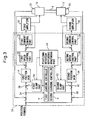
- Fig. 1 is a block diagram of a control device 2 according to a first embodiment of the invention.
- Control device 2 is used for rotating a crankpin 8 by means of first and second electric motors 10 and 12.
- Control device 2 periodically outputs a command for controlling the electric motors.
- first electric motor 10 In relation to first electric motor 10, when a position command (or a movement command) output from a numeric control device (not shown) is input to control device 2, a first position gain 14 outputs a speed command. Next, a first speed control part 16 outputs a torque command based on the speed command, a first current control part 18 outputs a voltage command based on the current command, and then a first amplifier 20 rotatably activates first electric motor 10.
- a first position detector 22 is attached to first electric motor 10 and a detected value from first position detector 22 is used for position feedback. Speed feedback and current feedback are also used for controlling the speed and the current of the electric motor, respectively.
- a second position gain 24 outputs a speed command.
- a second speed control part 26 outputs a torque command based on the speed command
- a second current control part 28 outputs a voltage command based on the current command
- a second amplifier 30 rotatably activates second electric motor 12.
- a second position detector 32 is attached to second electric motor 12 and a detected value from second position detector 32 is used for position feedback. Speed feedback and current feedback are also used for controlling the speed and the current of the electric motor, respectively.
- Control device 2 has a first positional deviation calculating part 34 for calculating a positional deviation of first electric motor 10, a first learning controller 4 for calculating an amount of correction of positional deviation based on the calculated positional deviation so that the positional deviation of the first electric motor is minimized, and a first positional deviation correcting part 36 for correcting the positional deviation of the first electric motor based on the calculated amount of correction of positional deviation.
- control device 2 has a second positional deviation calculating part 38 for calculating a positional deviation of second electric motor 12, a second learning controller 6 for calculating an amount of correction of positional deviation based on the calculated positional deviation so that the positional deviation of the second electric motor is minimized, and a second positional deviation correcting part 40 for correcting the positional deviation of the second electric motor based on the calculated amount of correction of positional deviation.
- First and second learning controllers 4 and 6 act independently each other so that the positional deviation of each electric motor is minimized, however, the learning controllers use the same parameter defining a response of learning control.
- each electric motor may have the same response, regardless of an imbalance in the load of each electric motor.
- a crankpin is held at both ends thereof and both ends are rotatably driven, even if the load applied to one electric motor is considerably larger than the load applied to another electric motor, according to the invention, by periodically repeating learning control, the response of each electric motor may finally converge on the predetermined value.
- each electric motor may have the same response, whereby a torsion of the workpiece may be avoided and rotational control with high accuracy may be achieved.
- Fig. 2 is a block diagram showing a preferred embodiment of each learning controller.
- Each of first and second learning controllers 4 and 6 has a low-pass filter 42, a memory 44 for storing periodic positional deviation data having the same period of time as the periodically repeated commands, a phase-lead compensator 46 for independently leading a phase of each electric motor based on the characteristic of each electric motor.
- a cut-off frequency of low-pass filter 42 is used to define a response of learning control, and the cut-off frequency of the low-pass filter of each learning controller is the same.
- a similar different response may occur due to an error in setting a control parameter for the electric motor. As the positional deviation may diverge in such cases, it is necessary to reduce a damage applied to the workpiece.
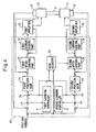
- a second embodiment as shown in Fig. 3 is intended to avoid the above disadvantages.
- control device 2A according to the second embodiment as shown in Fig. 3 is different from the first embodiment in that control device 2A has a monitoring part 48 for calculating and monitoring the difference between amounts of correction of positional deviation output from learning controllers 4 and 6, and first and second clamping parts 50 and 52 each for clamping the amount of correction of positional deviation output from each learning control part when the difference exceeds a predetermined range. Since the other components of control device 2A may be the same as those of control device 2 of the first embodiment, a detailed explanation thereof is omitted.
- monitoring part 48 and clamping parts 50, 52 Concrete functions of monitoring part 48 and clamping parts 50, 52 will be described below.
- M1 and M2 amounts of correction of first and second electric motors 10 and 12 calculated by first and second learning controllers 4 and 6 are referred to as M1 and M2, respectively.
- a monitoring level for the difference between the amounts of correction is referred to as Sa
- a disadvantageous load applied to the workpiece which may cause the distortion of the workpiece during a converging process of learning control, may be eliminated or reduced.
- the amount of correction when clamped, it generally takes longer time than in the first embodiment, to substantially eliminate the disadvantageous load. However, even in such a case, the disadvantageous load is ultimately eliminated.
- One possible way to reduce the above torque interference between the electric motors is to adjust a speed gain so that the response of each electric motor is equal to each other so as to improve the convergence performance of the deviation.
- each learning controller ultimately outputs an amount of correction so that the response of each electric motor coincides with a response predetermined in each learning controller.
- each electric motor may ultimately have the same response.
- it may take long time to make the response convergent since interference may occur between each electric motor because of the difference between the responses of the electric motors during the learning control.
- the second electric motor delays relative to the first electric motor during acceleration.
- an amount of correction is output in order to eliminate or reduce the delay.
- the amount of correction for the second electric motor is larger than that for the first electric motor.
- a control device 2B according to a third embodiment as shown in Fig. 4 has a gain adjuster 54 which is configured to automatically adjust a speed gain of one of the electric motors so that the difference between the amount of correction output by each learning controller, after the deviation sufficiently converges by learning control. Since the other components of control device 2B may be the same as those of the first embodiment, a detailed explanation thereof is omitted.
- Gain adjuster 54 calculates the difference between amounts of correction M1 and M2 of the positional deviation output by the first and second controllers, and automatically adjust the speed gain of the first or second electric motor (in the drawing, the second electric motor) so that the difference is decreased, preferably, minimized.
- the speed gain of the second electric motor includes an integral gain k1 and a proportional gain k2
- a formula for calculating gains k1(n) and k2(n) is described below.
- the expression "n” means a calculation result of the current sampling period
- the expression "n-1" means a calculation result of the previous sampling period.
- the character " ⁇ " is a constant which is experimentally or empirically determined.
- a second-order derivative Dr of the position command is used.
- k ⁇ 1 n k ⁇ 1 ⁇ n - 1 - ⁇ ⁇ Dr n ⁇ M ⁇ 1 n - M ⁇ 2 n
- k ⁇ 2 n k ⁇ 2 ⁇ n - 1 - ⁇ ⁇ Dr n ⁇ M ⁇ 1 n - M ⁇ 2 n
- the speed gain of each electric motor may be equivalent to each other, and thus the convergence rate of the learning control for driving the workpiece may be improved.
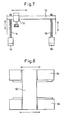
- Figs. 5 to 8 schematically show concrete examples to which the present invention may be applied.
- Fig. 5 shows a first mechanical constitution example, in which crankpin 8 is held at the both ends thereof and rotated by means of first and second electric motors 10 and 12, and then grinded by a grinder 56.
- Grinder 56 is configured to move relative to crankpin 8 by means of a linear motor 58.
- a stress may be applied to crankpin 8 if the response of each electric motor is different.
- the response of each electric motor may be equalized.
- Fig. 6 shows a second mechanical constitution example, in which a relatively large member or device 60 is moved in the vertical direction by means of a shaft 64 having a gear 62. Since device 60 is heavy, gear 62 is rotated by using two electric motors 66 and 68. In such a case, a stress may be applied to gear 62 if the response of each electric motor is different. However, according to the invention, the response of each electric motor may be equalized.
- Fig. 7 shows a third mechanical constitution example, in which a relatively large member or device 70 extending in the lateral direction (in the horizontal direction in Fig. 7 ) carries a heavy particle 72 such as an electric motor configured to move in the lateral direction.
- the horizontal balance of device 70 is maintained by means of an electric motor 76 having a shaft 74 and an electric motor 80 having a shaft 78.
- a load applied to electric motor 76 at the left side is larger than a load applied to electric motor 80 at the right side. According to the invention, even when the load imbalance exists, the response of each electric motor may be equalized.
- Fig. 8 shows a fourth mechanical constitution example, in which a table 82 is supported at both ends thereof by means of two linear motors 84 and 86, and then table 82 may be moved in the lateral direction.
- a stress may be applied to table 82 if the response of each linear motor is different.
- the response of each linear motor may be equalized and the stress applied to the table may be reduced.
- the control device of the present invention in the case that one object or workpiece is moved or driven by means of two electric motors, even when load imbalance exists between the electric motors, the response of each electric motor may be equalized, by independently arranging a learning controller on each electric motor, each learning having the same parameter defining the response of corresponding electric motor. Therefore, even when the workpiece has a low stiffness, a control operation with high accuracy may be carried out without generating significant deflection and distortion in the workpiece.
- a preferred embodiment of the learning controller is provided.
- the load may be reduced by providing the clamping part and the monitoring part for monitoring the difference of the amounts of correction of the positional deviation, to the control device of the invention.
- the convergence performance in the learning control may be improved.
Claims (3)
- Steuerungsvorrichtung (2) für Elektromotoren zum Bewegen eines zu bewegenden Objekts (8) unter Verwendung zweier Elektromotoren (10, 12) basierend auf sich periodisch wiederholenden Befehlen, wobei die Steuerungsvorrichtung aufweist:Positionsabweichungsberechnungsabschnitte (34, 38) zum Berechnen einer Positionsabweichung für jeden Elektromotor (10, 12);Lernsteuerabschnitte (4, 6) zum Berechnen eines Korrekturbetrags der Positionsabweichung derart, dass jede Positionsabweichung minimiert wird, die durch den Positionsabweichungsberechnungsabschnitt (34, 38) berechnet wird; undPositionsabweichungskorrekturabschnitte (36, 40) zum Korrigieren jeder Positionsabweichung basierend auf den Korrekturbetrag, der durch die Lernsteuerabschnitte (4, 6) berechnet wird,dadurch gekennzeichnet, dass jeder Lernsteuerabschnitt (4, 6) unabhängig von jedem Elektromotor (10, 12) angeordnet ist und ein Parameter für jeden eine Antwort auf die Lernsteuerung definierenden Lernsteuerabschnitt festgelegt wird, wobei die Parameter zueinander gleich sind,
und dass jeder Lernsteuerabschnitt (4, 6) aufweist:einen Tiefpassfilter (42), der die gleiche Grenzfrequenz aufweist;einen Speicher (44) zum Speichern der periodischen Positionsabweichungsdaten mit derselben Zeitspanne wie die periodisch wiederholten Befehle; undeinen Phasenführungskompensationsabschnitt (42) zum unabhängigen Führen einer Phase jedes Elektromotors basierend auf der Charakteristik jedes Elektromotors (10, 12). - Steuervorrichtung nach Anspruch 1, dadurch gekennzeichnet, dass die Steuervorrichtung ferner aufweist:einen Überwachungsabschnitt (48) zum Überwachen, ob die Differenz zwischen jedem Korrekturbetrag der Positionsabweichung, die von jedem Lernsteuerabschnitt (4, 6) ausgegeben wird, innerhalb eines vorbestimmten Bereichs liegt; undeinen Klemmabschnitt (50, 52) zum Klemmen einer Ausgabe jedes Lernsteuerabschnitts (4, 6), wenn die Differenz den vorbestimmten Bereich überschreitet.
- Steuervorrichtung nach Anspruch 1, dadurch gekennzeichnet, dass die Steuervorrichtung ferner einen Anstiegsanpassungsabschnitt (54) zum automatischen Anpassen eines Geschwindigkeitsanstiegs eines der Elektromotoren (10, 12) derart aufweist, dass die Differenz zwischen jedem Korrekturbetrag der Positionsabweichung, die von jedem Lernsteuerabschnitt (4, 6) ausgegeben werden, minimiert wird.
Applications Claiming Priority (1)
| Application Number | Priority Date | Filing Date | Title |
|---|---|---|---|
| JP2007274131A JP4323542B2 (ja) | 2007-10-22 | 2007-10-22 | 学習制御機能を備えた電動機の制御装置 |
Publications (2)
| Publication Number | Publication Date |
|---|---|
| EP2053477A1 EP2053477A1 (de) | 2009-04-29 |
| EP2053477B1 true EP2053477B1 (de) | 2012-07-18 |
Family
ID=39942756
Family Applications (1)
| Application Number | Title | Priority Date | Filing Date |
|---|---|---|---|
| EP08016377A Active EP2053477B1 (de) | 2007-10-22 | 2008-09-17 | Steuervorrichtung mit Lernfunktion für Elektromotoren |
Country Status (4)
| Country | Link |
|---|---|
| US (1) | US8305016B2 (de) |
| EP (1) | EP2053477B1 (de) |
| JP (1) | JP4323542B2 (de) |
| CN (1) | CN101419445B (de) |
Families Citing this family (19)
| Publication number | Priority date | Publication date | Assignee | Title |
|---|---|---|---|---|
| DE112012002234B4 (de) * | 2011-05-24 | 2017-08-17 | Mitsubishi Electric Corporation | Motorsteuerungsvorrichtung |
| JP5694111B2 (ja) * | 2011-09-30 | 2015-04-01 | 株式会社東芝 | プラント制御装置、プラント制御方法およびプログラム |
| JP5919070B2 (ja) * | 2012-04-06 | 2016-05-18 | オークマ株式会社 | 位置制御装置 |
| EP3829051B1 (de) * | 2014-02-25 | 2024-01-31 | Panasonic Intellectual Property Management Co., Ltd. | In einer elektromotorsteuerungsvorrichtung verwendetes steuerparametereinstellungsverfahren und elektromotorsteuerungsvorrichtung mit besagtem steuerparametereinstellungsverfahren |
| JP5873140B2 (ja) * | 2014-06-25 | 2016-03-01 | ファナック株式会社 | 同期制御装置 |
| JP5897662B2 (ja) * | 2014-07-30 | 2016-03-30 | ファナック株式会社 | 複数軸の加工精度を向上させるサーボモータの制御装置 |
| JP6564175B2 (ja) * | 2014-09-29 | 2019-08-21 | 川崎重工業株式会社 | ロボットの制御装置および制御方法 |
| JP6331225B2 (ja) * | 2015-08-19 | 2018-05-30 | 株式会社安川電機 | モータ制御装置、位置制御システム、及びモータ制御方法 |
| JP6544219B2 (ja) * | 2015-11-30 | 2019-07-17 | オムロン株式会社 | 制御装置 |
| JP6237938B1 (ja) * | 2016-10-18 | 2017-11-29 | 株式会社安川電機 | 多軸モータ制御システム、モータ制御装置、及びモータ制御方法 |
| JP7027808B2 (ja) * | 2016-11-11 | 2022-03-02 | 株式会社デンソー | 回転電機制御装置、および、これを用いた電動パワーステアリング装置 |
| EP3339185B1 (de) * | 2016-12-21 | 2019-05-15 | Airbus Defence and Space GmbH | Luftfahrzeugantriebsvorrichtung sowie damit versehenes luftfahrzeug |
| DE102017211061A1 (de) * | 2017-06-29 | 2019-01-03 | Siemens Aktiengesellschaft | Synchronisierungsverfahren zum Synchronisieren einer Mehrzahl von Aktoren sowie Vorrichtungen zu dessen Durchführung |
| JP6697491B2 (ja) | 2018-01-25 | 2020-05-20 | ファナック株式会社 | 機械学習装置、サーボモータ制御装置、サーボモータ制御システム、及び機械学習方法 |
| JP6698733B2 (ja) | 2018-04-06 | 2020-05-27 | ファナック株式会社 | モータエンコーダ及びセンサを用いて学習制御を行うロボットシステム |
| JP6841801B2 (ja) * | 2018-08-30 | 2021-03-10 | ファナック株式会社 | 機械学習装置、制御システム及び機械学習方法 |
| JP7199244B2 (ja) * | 2019-02-08 | 2023-01-05 | ミネベアミツミ株式会社 | モータ駆動制御装置及びモータの駆動制御方法 |
| JP7238525B2 (ja) * | 2019-03-25 | 2023-03-14 | 株式会社デンソー | モータ制御装置 |
| JP2022060029A (ja) * | 2020-10-02 | 2022-04-14 | 川崎重工業株式会社 | 駆動装置及び搬送装置 |
Family Cites Families (15)
| Publication number | Priority date | Publication date | Assignee | Title |
|---|---|---|---|---|
| US4094481A (en) * | 1977-06-30 | 1978-06-13 | Sperry Rand Corporation | Fail passive dual servo with continuous motor speed and acceleration and monitoring |
| US4206620A (en) * | 1979-01-12 | 1980-06-10 | Eaton-Leonard Corporation | Dual motor carriage drive |
| JPH0297291A (ja) * | 1988-09-30 | 1990-04-09 | Omron Tateisi Electron Co | モータの自動制御装置 |
| JP3010583B2 (ja) * | 1989-12-31 | 2000-02-21 | 株式会社エスジー | 複数軸の同調制御方式 |
| JPH0511853A (ja) * | 1991-06-28 | 1993-01-22 | Matsushita Electric Ind Co Ltd | 2軸同期駆動装置 |
| JPH05306758A (ja) | 1992-05-06 | 1993-11-19 | Mazda Motor Corp | 自動変速機の変速制御装置 |
| JP2574983B2 (ja) * | 1993-04-06 | 1997-01-22 | 本田技研工業株式会社 | マルチタスク制御システム |
| JPH09275695A (ja) * | 1996-04-02 | 1997-10-21 | Minolta Co Ltd | モータ制御装置 |
| JPH11305839A (ja) | 1998-04-21 | 1999-11-05 | Fanuc Ltd | 複数のサーボモータの制御方法 |
| JP3492583B2 (ja) * | 2000-03-27 | 2004-02-03 | ファナック株式会社 | サーボ制御装置 |
| JP2003200332A (ja) * | 2001-12-27 | 2003-07-15 | Fanuc Ltd | 歯車加工用制御装置 |
| JP3923047B2 (ja) * | 2003-03-04 | 2007-05-30 | ファナック株式会社 | 同期制御装置 |
| JP4299793B2 (ja) * | 2005-01-20 | 2009-07-22 | ファナック株式会社 | 制御装置 |
| JP4361071B2 (ja) | 2005-07-08 | 2009-11-11 | ファナック株式会社 | サーボ制御装置 |
| JP2007274131A (ja) | 2006-03-30 | 2007-10-18 | Yamaha Corp | 拡声システム及び集音装置 |
-
2007
- 2007-10-22 JP JP2007274131A patent/JP4323542B2/ja active Active
-
2008
- 2008-09-17 US US12/212,058 patent/US8305016B2/en active Active
- 2008-09-17 EP EP08016377A patent/EP2053477B1/de active Active
- 2008-09-19 CN CN2008101491664A patent/CN101419445B/zh active Active
Also Published As
| Publication number | Publication date |
|---|---|
| JP2009106034A (ja) | 2009-05-14 |
| CN101419445B (zh) | 2013-08-07 |
| JP4323542B2 (ja) | 2009-09-02 |
| EP2053477A1 (de) | 2009-04-29 |
| US8305016B2 (en) | 2012-11-06 |
| US20090102409A1 (en) | 2009-04-23 |
| CN101419445A (zh) | 2009-04-29 |
Similar Documents
| Publication | Publication Date | Title |
|---|---|---|
| EP2053477B1 (de) | Steuervorrichtung mit Lernfunktion für Elektromotoren | |
| EP1667001B1 (de) | Steuervorrichtung | |
| JP4813912B2 (ja) | 未加工品と工作機械の工具との間の相対運動の運動分割方法、および運動分割を実施するための工作機械 | |
| CN109664297B (zh) | 机器人的振动抑制方法、系统、装置及计算机可读存储器 | |
| US10007280B2 (en) | Apparatus and method for controlling and regulating a multi-element system | |
| Erkorkmaz et al. | High speed CNC system design. Part III: high speed tracking and contouring control of feed drives | |
| EP1291747B1 (de) | Positionierungs-servosteuerung | |
| JP4944806B2 (ja) | 位置制御装置 | |
| EP3118710B1 (de) | Füllschachtsteuerungsverfahren sowie arbeitsvorrichtung mit numerischer steuerung | |
| EP1143315A2 (de) | Servosteuerung | |
| US9304504B2 (en) | Servo controller for reducing interference between axes in machining | |
| Sencer et al. | Design and application of a sliding mode controller for accurate motion synchronization of dual servo systems | |
| Ishizaki et al. | Cross Coupling Controller for Accurate Motion Synchronization of Dual Servo Systems. | |
| EP3321755B1 (de) | Werkzeugmaschine und parameteranpassungsverfahren dafür | |
| JP4612032B2 (ja) | 工作機械用制御装置 | |
| US9501054B2 (en) | Motor control system compensating interference between axes | |
| JP4867105B2 (ja) | 数値制御装置 | |
| JP6620195B2 (ja) | モデルを利用した誤差補償付き被加工材の加工方法 | |
| JP2003005838A (ja) | サーボ制御方法 | |
| JP3943061B2 (ja) | サーボ制御装置 | |
| JP6068779B2 (ja) | 直進型及び回転型ロボットの制御装置 | |
| CN112039403A (zh) | 电动机控制装置和产业机械 | |
| JPH0922304A (ja) | 振動抑制装置 | |
| JPS63251108A (ja) | 重量バランス制御装置 | |
| KR20050067684A (ko) | 상한 돌기 방지를 위한 공작기계의 서보모터 속도루프게인류 제어장치 및 방법 |
Legal Events
| Date | Code | Title | Description |
|---|---|---|---|
| PUAI | Public reference made under article 153(3) epc to a published international application that has entered the european phase |
Free format text: ORIGINAL CODE: 0009012 |
|
| AK | Designated contracting states |
Kind code of ref document: A1 Designated state(s): AT BE BG CH CY CZ DE DK EE ES FI FR GB GR HR HU IE IS IT LI LT LU LV MC MT NL NO PL PT RO SE SI SK TR |
|
| AX | Request for extension of the european patent |
Extension state: AL BA MK RS |
|
| 17P | Request for examination filed |
Effective date: 20090428 |
|
| AKX | Designation fees paid |
Designated state(s): DE |
|
| 17Q | First examination report despatched |
Effective date: 20100520 |
|
| RAP1 | Party data changed (applicant data changed or rights of an application transferred) |
Owner name: FANUC CORPORATION |
|
| GRAP | Despatch of communication of intention to grant a patent |
Free format text: ORIGINAL CODE: EPIDOSNIGR1 |
|
| RIN1 | Information on inventor provided before grant (corrected) |
Inventor name: OKITA, TADASHI Inventor name: SONODA, NAOTO Inventor name: TOYOZAWA, YUKIO |
|
| GRAS | Grant fee paid |
Free format text: ORIGINAL CODE: EPIDOSNIGR3 |
|
| GRAA | (expected) grant |
Free format text: ORIGINAL CODE: 0009210 |
|
| AK | Designated contracting states |
Kind code of ref document: B1 Designated state(s): DE |
|
| REG | Reference to a national code |
Ref country code: DE Ref legal event code: R096 Ref document number: 602008017238 Country of ref document: DE Effective date: 20120913 |
|
| PLBE | No opposition filed within time limit |
Free format text: ORIGINAL CODE: 0009261 |
|
| STAA | Information on the status of an ep patent application or granted ep patent |
Free format text: STATUS: NO OPPOSITION FILED WITHIN TIME LIMIT |
|
| 26N | No opposition filed |
Effective date: 20130419 |
|
| REG | Reference to a national code |
Ref country code: DE Ref legal event code: R097 Ref document number: 602008017238 Country of ref document: DE Effective date: 20130419 |
|
| PGFP | Annual fee paid to national office [announced via postgrant information from national office to epo] |
Ref country code: DE Payment date: 20230802 Year of fee payment: 16 |