EP2053264B1 - Disk brake and method of producing the same - Google Patents
Disk brake and method of producing the same Download PDFInfo
- Publication number
- EP2053264B1 EP2053264B1 EP08017109.3A EP08017109A EP2053264B1 EP 2053264 B1 EP2053264 B1 EP 2053264B1 EP 08017109 A EP08017109 A EP 08017109A EP 2053264 B1 EP2053264 B1 EP 2053264B1
- Authority
- EP
- European Patent Office
- Prior art keywords
- cover member
- blind hole
- cylinder
- cylinder body
- projection
- Prior art date
- Legal status (The legal status is an assumption and is not a legal conclusion. Google has not performed a legal analysis and makes no representation as to the accuracy of the status listed.)
- Active
Links
Images


Classifications
-
- F—MECHANICAL ENGINEERING; LIGHTING; HEATING; WEAPONS; BLASTING
- F16—ENGINEERING ELEMENTS AND UNITS; GENERAL MEASURES FOR PRODUCING AND MAINTAINING EFFECTIVE FUNCTIONING OF MACHINES OR INSTALLATIONS; THERMAL INSULATION IN GENERAL
- F16D—COUPLINGS FOR TRANSMITTING ROTATION; CLUTCHES; BRAKES
- F16D55/00—Brakes with substantially-radial braking surfaces pressed together in axial direction, e.g. disc brakes
- F16D55/02—Brakes with substantially-radial braking surfaces pressed together in axial direction, e.g. disc brakes with axially-movable discs or pads pressed against axially-located rotating members
- F16D55/22—Brakes with substantially-radial braking surfaces pressed together in axial direction, e.g. disc brakes with axially-movable discs or pads pressed against axially-located rotating members by clamping an axially-located rotating disc between movable braking members, e.g. movable brake discs or brake pads
- F16D55/228—Brakes with substantially-radial braking surfaces pressed together in axial direction, e.g. disc brakes with axially-movable discs or pads pressed against axially-located rotating members by clamping an axially-located rotating disc between movable braking members, e.g. movable brake discs or brake pads with a separate actuating member for each side
-
- F—MECHANICAL ENGINEERING; LIGHTING; HEATING; WEAPONS; BLASTING
- F16—ENGINEERING ELEMENTS AND UNITS; GENERAL MEASURES FOR PRODUCING AND MAINTAINING EFFECTIVE FUNCTIONING OF MACHINES OR INSTALLATIONS; THERMAL INSULATION IN GENERAL
- F16D—COUPLINGS FOR TRANSMITTING ROTATION; CLUTCHES; BRAKES
- F16D55/00—Brakes with substantially-radial braking surfaces pressed together in axial direction, e.g. disc brakes
- F16D2055/0004—Parts or details of disc brakes
- F16D2055/0016—Brake calipers
- F16D2055/002—Brake calipers assembled from a plurality of parts
-
- F—MECHANICAL ENGINEERING; LIGHTING; HEATING; WEAPONS; BLASTING
- F16—ENGINEERING ELEMENTS AND UNITS; GENERAL MEASURES FOR PRODUCING AND MAINTAINING EFFECTIVE FUNCTIONING OF MACHINES OR INSTALLATIONS; THERMAL INSULATION IN GENERAL
- F16D—COUPLINGS FOR TRANSMITTING ROTATION; CLUTCHES; BRAKES
- F16D55/00—Brakes with substantially-radial braking surfaces pressed together in axial direction, e.g. disc brakes
- F16D2055/0075—Constructional features of axially engaged brakes
- F16D2055/0091—Plural actuators arranged side by side on the same side of the rotor
-
- F—MECHANICAL ENGINEERING; LIGHTING; HEATING; WEAPONS; BLASTING
- F16—ENGINEERING ELEMENTS AND UNITS; GENERAL MEASURES FOR PRODUCING AND MAINTAINING EFFECTIVE FUNCTIONING OF MACHINES OR INSTALLATIONS; THERMAL INSULATION IN GENERAL
- F16D—COUPLINGS FOR TRANSMITTING ROTATION; CLUTCHES; BRAKES
- F16D2121/00—Type of actuator operation force
- F16D2121/02—Fluid pressure
-
- F—MECHANICAL ENGINEERING; LIGHTING; HEATING; WEAPONS; BLASTING
- F16—ENGINEERING ELEMENTS AND UNITS; GENERAL MEASURES FOR PRODUCING AND MAINTAINING EFFECTIVE FUNCTIONING OF MACHINES OR INSTALLATIONS; THERMAL INSULATION IN GENERAL
- F16D—COUPLINGS FOR TRANSMITTING ROTATION; CLUTCHES; BRAKES
- F16D2125/00—Components of actuators
- F16D2125/02—Fluid-pressure mechanisms
- F16D2125/04—Cylinders
-
- F—MECHANICAL ENGINEERING; LIGHTING; HEATING; WEAPONS; BLASTING
- F16—ENGINEERING ELEMENTS AND UNITS; GENERAL MEASURES FOR PRODUCING AND MAINTAINING EFFECTIVE FUNCTIONING OF MACHINES OR INSTALLATIONS; THERMAL INSULATION IN GENERAL
- F16D—COUPLINGS FOR TRANSMITTING ROTATION; CLUTCHES; BRAKES
- F16D2250/00—Manufacturing; Assembly
- F16D2250/0061—Joining
- F16D2250/0076—Welding, brazing
-
- F—MECHANICAL ENGINEERING; LIGHTING; HEATING; WEAPONS; BLASTING
- F16—ENGINEERING ELEMENTS AND UNITS; GENERAL MEASURES FOR PRODUCING AND MAINTAINING EFFECTIVE FUNCTIONING OF MACHINES OR INSTALLATIONS; THERMAL INSULATION IN GENERAL
- F16D—COUPLINGS FOR TRANSMITTING ROTATION; CLUTCHES; BRAKES
- F16D2250/00—Manufacturing; Assembly
- F16D2250/0092—Tools or machines for producing linings
-
- Y—GENERAL TAGGING OF NEW TECHNOLOGICAL DEVELOPMENTS; GENERAL TAGGING OF CROSS-SECTIONAL TECHNOLOGIES SPANNING OVER SEVERAL SECTIONS OF THE IPC; TECHNICAL SUBJECTS COVERED BY FORMER USPC CROSS-REFERENCE ART COLLECTIONS [XRACs] AND DIGESTS
- Y10—TECHNICAL SUBJECTS COVERED BY FORMER USPC
- Y10T—TECHNICAL SUBJECTS COVERED BY FORMER US CLASSIFICATION
- Y10T29/00—Metal working
- Y10T29/49—Method of mechanical manufacture
- Y10T29/49826—Assembling or joining
Definitions
- the present invention provides a disk brake according to claim 1.
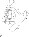
- Figs. 8 to 10 show one cover member 43 that is fitted to the opening 45 of the inner cylinder portion 21.
- the cover member 43 is, as shown in these figures, formed in a disk shape from an aluminum alloy or the like, and has a projection 60 in the center of one end surface thereof in the direction of thickness thereof (i.e. axial direction).
- the cover member 43 further has a blind hole 61 in the center of the other end surface thereof.
- the cover member 43 is fitted to the opening 45 such that the side thereof provided with the projection 60 faces inside the bore 26 of the inner cylinder portion 21.
- the projection 60 having a small area limits the retract position of the piston 17 accommodated in the bore 26 when the piston 17 is most retracted. Specifically, the projection 60 is provided for the following reason.
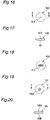
- the cover members 43 are welded to the openings 45 over the entire circumferences thereof, and, as shown in Fig. 11 , residual impressions 78 due to the friction stir welding process are formed on the end surface of the caliper body main part 46.
- the end surface of the caliper body main part 46 has somewhat undulating weld beads 77 formed around the outer peripheries of the cover members 43, but the residual impressions 78, which are relatively deep recesses, are formed only at the withdrawal points where the welding tool 71 is withdrawn from the caliper body main part 46.
- Each residual impression 78 consists of a center hole 79 corresponding to the tip shaft portion 73 of the welding tool 71 and a peripheral recess 80 corresponding to the large-diameter shaft portion 72 of the welding tool 71.
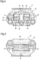
- the present invention is applied to a disk brake having a cylinder slidably accommodating a piston that presses a brake pad against a disk, in which the cylinder is formed from a plate-shaped cover member constituting the bottom of the cylinder and a cylinder body having an opening that is closed with the cover member, and in which the cover member is Joined to the cylinder body to close the opening.
- a projection is provided on one side of the cover member that faces inside the cylinder, and a blind hole is provided on the other side of the cover member. Therefore, the installed orientation of the cover member can be readily and accurately judged from the presence or absence of the blind hole after the cylinder bottom has been subjected to face cutting. In addition, the time required for the product inspection can be shortened.
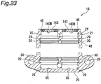
- friction stir welding is applied, as shown in Fig. 22 , to the joint interfaces between the cover members 43 and the respective peripheral walls of the openings 45. Thereafter, the circular arc of each weld bead 77 resulting from the friction stir welding and the position of the first projection 160A of the associated cover member 143 are compared with each other to evaluate whether or not the friction stir welding has been performed along an appropriate locus.
- the opening 45-side bottom surface of the semi-fabricated product of the caliper body 16 is subjected to face cutting to remove, as shown in Fig. 23 , the first projection 160A, which is located on the outer side of each cover member 143, from the bottom of the semi-fabricated caliper body 16, together with the weld beads 77 including burrs.
Landscapes
- Engineering & Computer Science (AREA)
- General Engineering & Computer Science (AREA)
- Mechanical Engineering (AREA)
- Braking Arrangements (AREA)
Applications Claiming Priority (1)
| Application Number | Priority Date | Filing Date | Title |
|---|---|---|---|
| JP2007274385A JP4832402B2 (ja) | 2007-10-22 | 2007-10-22 | ディスクブレーキおよびディスクブレーキの製造方法 |
Publications (2)
| Publication Number | Publication Date |
|---|---|
| EP2053264A1 EP2053264A1 (en) | 2009-04-29 |
| EP2053264B1 true EP2053264B1 (en) | 2020-01-01 |
Family
ID=40348091
Family Applications (1)
| Application Number | Title | Priority Date | Filing Date |
|---|---|---|---|
| EP08017109.3A Active EP2053264B1 (en) | 2007-10-22 | 2008-09-29 | Disk brake and method of producing the same |
Country Status (4)
| Country | Link |
|---|---|
| US (1) | US8807298B2 (enExample) |
| EP (1) | EP2053264B1 (enExample) |
| JP (1) | JP4832402B2 (enExample) |
| CN (1) | CN101418838B (enExample) |
Families Citing this family (13)
| Publication number | Priority date | Publication date | Assignee | Title |
|---|---|---|---|---|
| JP5292191B2 (ja) * | 2009-06-08 | 2013-09-18 | 日立オートモティブシステムズ株式会社 | ディスクブレーキおよびその製造方法 |
| JP5409144B2 (ja) * | 2009-06-30 | 2014-02-05 | 日立オートモティブシステムズ株式会社 | ディスクブレーキおよびその製造方法 |
| JP5802453B2 (ja) | 2010-10-29 | 2015-10-28 | 日立オートモティブシステムズ株式会社 | ディスクブレーキの製造方法 |
| US8789663B2 (en) * | 2011-08-26 | 2014-07-29 | Ashima Ltd. | Bicycle hydraulic brake clamp |
| CN104204594B (zh) * | 2012-04-07 | 2016-11-02 | 丰田自动车株式会社 | 摩擦制动装置 |
| JP6071132B2 (ja) * | 2013-03-28 | 2017-02-01 | Kyb株式会社 | 接合体 |
| CN104976250A (zh) * | 2014-04-05 | 2015-10-14 | 钱江帆 | 大制动力碟式刹车装置 |
| DE102016115176A1 (de) * | 2016-08-16 | 2018-02-22 | Bpw Bergische Achsen Kg | Verfahren zur Innenbearbeitung eines Bremssattels einer Scheibenbremse |
| GB2555482B (en) * | 2016-10-27 | 2021-12-01 | Alcon Components Ltd | Cooling ducts for disc brake caliper and method of manufacture thereof |
| CN107009095B (zh) * | 2017-04-08 | 2020-04-10 | 重庆川页科技发展有限公司 | 汽车制动盘底板的制作方法 |
| JP6746789B2 (ja) * | 2017-06-30 | 2020-08-26 | 日立オートモティブシステムズ株式会社 | ディスクブレーキ |
| CN114633081A (zh) * | 2022-04-20 | 2022-06-17 | 颍上县皖工精艺工量具制造有限公司 | 一种新型游尺加工工艺 |
| WO2024100929A1 (ja) * | 2022-11-07 | 2024-05-16 | 日立Astemo株式会社 | ディスクブレーキ及びキャリパボディ |
Family Cites Families (40)
| Publication number | Priority date | Publication date | Assignee | Title |
|---|---|---|---|---|
| US3424276A (en) * | 1967-03-03 | 1969-01-28 | Kelsey Hayes Co | Opposed piston disk brake |
| FR1553530A (enExample) * | 1967-07-12 | 1969-01-10 | ||
| US3490343A (en) * | 1967-10-12 | 1970-01-20 | Dayton Steel Foundry Co | Hydraulic disk brakes |
| JPS54129262A (en) * | 1978-03-30 | 1979-10-06 | Nissan Motor Co Ltd | Disc brake |
| JPS58150637A (ja) * | 1982-02-27 | 1983-09-07 | 大下 一義 | 可変断熱内装材 |
| DE3245157A1 (de) | 1982-12-07 | 1984-06-07 | Alfred Teves Gmbh, 6000 Frankfurt | Bremssattelgehaeuse, insbesondere fuer eine teilbelag-scheibenbremse eines kraftfahrzeuges und verfahren zur herstellung des gehaeuses |
| JPH11111246A (ja) * | 1997-08-06 | 1999-04-23 | Toshiba Corp | 密閉電池およびその製造方法 |
| DE68913201T2 (de) * | 1988-05-03 | 1994-07-28 | Ceram Eng Pty Ltd | Bremseinheit. |
| JP3264502B2 (ja) * | 1991-10-02 | 2002-03-11 | トキコ株式会社 | ディスクブレーキ |
| GB9125978D0 (en) * | 1991-12-06 | 1992-02-05 | Welding Inst | Hot shear butt welding |
| JPH0674262A (ja) * | 1992-08-28 | 1994-03-15 | Nippon Plast Co Ltd | 回転ダンパー |
| US5615754A (en) * | 1994-03-18 | 1997-04-01 | Tokico Ltd. | Disc brake |
| JPH0828614A (ja) * | 1994-07-19 | 1996-02-02 | Nisshinbo Ind Inc | ディスクブレーキ装置 |
| US5575358A (en) * | 1994-08-17 | 1996-11-19 | Kelsey-Hayes Company | Molded piston having metallic cover for disc brake assembly |
| JP3040670B2 (ja) * | 1994-08-22 | 2000-05-15 | ファナック株式会社 | レーザセンサを用いた溶接線追従方法及びロボット制御装置 |
| JPH08312696A (ja) * | 1995-05-17 | 1996-11-26 | Sumitomo Electric Ind Ltd | ディスクブレーキ |
| DE19626608B4 (de) * | 1996-07-02 | 2004-11-11 | Boehringer Werkzeugmaschinen Gmbh | Verfahren zur spanenden Bearbeitung |
| JP3568752B2 (ja) * | 1997-10-03 | 2004-09-22 | 住友電気工業株式会社 | マルチポット型ディスクブレーキ |
| US6175778B1 (en) * | 1998-06-03 | 2001-01-16 | Performance Friction Corporation | Computer vision-based rotor machining system apparatus and method |
| JP2000145836A (ja) * | 1998-11-06 | 2000-05-26 | Nissin Kogyo Co Ltd | 車両用ディスクブレーキのキャリパボディ |
| JP2000304029A (ja) * | 1999-04-21 | 2000-10-31 | Tokai Rubber Ind Ltd | ボールジョイント |
| JP2001027267A (ja) * | 1999-07-15 | 2001-01-30 | Sumitomo Electric Ind Ltd | キャリパボディ |
| JP3908417B2 (ja) * | 1999-08-19 | 2007-04-25 | 大和製罐株式会社 | 開口仮封止栓付缶 |
| JP2001107998A (ja) * | 1999-10-08 | 2001-04-17 | Nisshinbo Ind Inc | ディスクブレーキのシリンダ装置 |
| JP3575748B2 (ja) * | 2000-03-06 | 2004-10-13 | 株式会社日立製作所 | 摩擦攪拌接合方法 |
| JP4432266B2 (ja) * | 2001-02-27 | 2010-03-17 | 株式会社アドヴィックス | ディスクブレーキ |
| JP2002333043A (ja) * | 2001-05-10 | 2002-11-22 | Sumitomo Denko Brake Systems Kk | ディスクブレーキ |
| JP2003120729A (ja) * | 2001-10-12 | 2003-04-23 | Nissin Kogyo Co Ltd | 車両用ディスクブレーキのキャリパボディ |
| JP2003148524A (ja) * | 2001-11-14 | 2003-05-21 | Nissin Kogyo Co Ltd | 車両用ディスクブレーキのキャリパボディ |
| JP4590856B2 (ja) * | 2003-11-14 | 2010-12-01 | 新神戸電機株式会社 | 密閉型電池 |
| JP2005163809A (ja) * | 2003-11-28 | 2005-06-23 | Hitachi Ltd | ディスクブレーキ |
| DE102004001495A1 (de) * | 2004-01-09 | 2005-08-11 | Gustav Magenwirth Gmbh & Co. Kg | Bremszange und Verfahren zur Herstellung eines Gehäuses einer Bremszange |
| JP2007010136A (ja) * | 2005-02-07 | 2007-01-18 | Hitachi Ltd | シリンダ装置、ディスクブレーキおよびマスタシリンダ |
| US8672100B2 (en) * | 2005-02-07 | 2014-03-18 | Hitachi, Ltd. | Cylinder apparatus and disk brake |
| ITMI20060016A1 (it) | 2006-01-05 | 2007-07-06 | Sunstar Logistic Singapore Pte Ltd | Metodo di fabbricazione di pinze per freni a disco perfezionato |
| JP4864486B2 (ja) * | 2006-02-24 | 2012-02-01 | 日立オートモティブシステムズ株式会社 | ディスクブレーキの製造方法 |
| JP4828255B2 (ja) * | 2006-02-24 | 2011-11-30 | 日立オートモティブシステムズ株式会社 | ディスクブレーキ |
| JP4826942B2 (ja) * | 2006-03-31 | 2011-11-30 | 日立オートモティブシステムズ株式会社 | 電動ディスクブレーキ、及び電動ディスクブレーキの組立方法 |
| JP4449933B2 (ja) | 2006-03-31 | 2010-04-14 | ブラザー工業株式会社 | 電子証明書発行システム、電子証明書発行装置、通信装置、及び、プログラム |
| JP2008128294A (ja) * | 2006-11-17 | 2008-06-05 | Advics:Kk | 多ポット型ディスクブレーキ |
-
2007
- 2007-10-22 JP JP2007274385A patent/JP4832402B2/ja active Active
-
2008
- 2008-09-23 US US12/232,726 patent/US8807298B2/en active Active
- 2008-09-28 CN CN200810173762.6A patent/CN101418838B/zh active Active
- 2008-09-29 EP EP08017109.3A patent/EP2053264B1/en active Active
Non-Patent Citations (1)
| Title |
|---|
| None * |
Also Published As
| Publication number | Publication date |
|---|---|
| JP4832402B2 (ja) | 2011-12-07 |
| JP2009103187A (ja) | 2009-05-14 |
| US8807298B2 (en) | 2014-08-19 |
| CN101418838A (zh) | 2009-04-29 |
| CN101418838B (zh) | 2014-05-14 |
| EP2053264A1 (en) | 2009-04-29 |
| US20090101454A1 (en) | 2009-04-23 |
Similar Documents
| Publication | Publication Date | Title |
|---|---|---|
| EP2053264B1 (en) | Disk brake and method of producing the same | |
| US7950504B2 (en) | Disk brake | |
| CN101907139B (zh) | 盘式制动器及其制造方法 | |
| CN102537146B (zh) | 盘式制动器 | |
| EP1688207B1 (en) | Cylinder apparatus and disk brake | |
| JP2010014190A (ja) | フローティングブレーキディスク | |
| JP4294281B2 (ja) | 2ピースホイールの製造方法 | |
| JP2007285344A (ja) | ディスクブレーキ及びその製造方法 | |
| JP4339092B2 (ja) | キャリパボディの製造方法 | |
| JP5203152B2 (ja) | ディスクブレーキの製造方法 | |
| EP2270352B1 (en) | Disk brake | |
| JP2007225057A (ja) | ディスクブレーキ及びその製造方法 | |
| WO2024100929A1 (ja) | ディスクブレーキ及びキャリパボディ | |
| EP4470854A1 (en) | Brake apparatus for vehicle | |
| JP4823716B2 (ja) | ディスクブレーキ | |
| JP7045930B2 (ja) | ブーツの組み付け方法 | |
| KR200388904Y1 (ko) | 자동차 에이비에스용 센서링 | |
| JP2011137483A (ja) | ディスクブレーキ | |
| JP2012017816A (ja) | 車両のバックプレート取付フランジ |
Legal Events
| Date | Code | Title | Description |
|---|---|---|---|
| PUAI | Public reference made under article 153(3) epc to a published international application that has entered the european phase |
Free format text: ORIGINAL CODE: 0009012 |
|
| AK | Designated contracting states |
Kind code of ref document: A1 Designated state(s): AT BE BG CH CY CZ DE DK EE ES FI FR GB GR HR HU IE IS IT LI LT LU LV MC MT NL NO PL PT RO SE SI SK TR |
|
| AX | Request for extension of the european patent |
Extension state: AL BA MK RS |
|
| 17P | Request for examination filed |
Effective date: 20091029 |
|
| AKX | Designation fees paid |
Designated state(s): DE IT |
|
| 17Q | First examination report despatched |
Effective date: 20120731 |
|
| GRAP | Despatch of communication of intention to grant a patent |
Free format text: ORIGINAL CODE: EPIDOSNIGR1 |
|
| INTG | Intention to grant announced |
Effective date: 20190805 |
|
| GRAS | Grant fee paid |
Free format text: ORIGINAL CODE: EPIDOSNIGR3 |
|
| GRAA | (expected) grant |
Free format text: ORIGINAL CODE: 0009210 |
|
| AK | Designated contracting states |
Kind code of ref document: B1 Designated state(s): DE IT |
|
| RIN1 | Information on inventor provided before grant (corrected) |
Inventor name: NAGASAWA, JUNICHI Inventor name: NANRI, KEISUKE Inventor name: MATSUI, YOSHIMASA Inventor name: NOMURA, KIYOTAKA Inventor name: TAKAHASHI, JUN Inventor name: KOBAYASHI, YUICHI |
|
| REG | Reference to a national code |
Ref country code: DE Ref legal event code: R096 Ref document number: 602008061918 Country of ref document: DE |
|
| REG | Reference to a national code |
Ref country code: DE Ref legal event code: R097 Ref document number: 602008061918 Country of ref document: DE |
|
| PLBE | No opposition filed within time limit |
Free format text: ORIGINAL CODE: 0009261 |
|
| STAA | Information on the status of an ep patent application or granted ep patent |
Free format text: STATUS: NO OPPOSITION FILED WITHIN TIME LIMIT |
|
| 26N | No opposition filed |
Effective date: 20201002 |
|
| REG | Reference to a national code |
Ref country code: DE Ref legal event code: R081 Ref document number: 602008061918 Country of ref document: DE Owner name: HITACHI ASTEMO, LTD., HITACHINAKA-SHI, JP Free format text: FORMER OWNER: HITACHI, LTD., TOKYO, JP |
|
| PGFP | Annual fee paid to national office [announced via postgrant information from national office to epo] |
Ref country code: DE Payment date: 20250805 Year of fee payment: 18 |
|
| PGFP | Annual fee paid to national office [announced via postgrant information from national office to epo] |
Ref country code: IT Payment date: 20250825 Year of fee payment: 18 |