EP2052877B1 - Spannungsreduzierungssystem für Radnaben - Google Patents
Spannungsreduzierungssystem für Radnaben Download PDFInfo
- Publication number
- EP2052877B1 EP2052877B1 EP08251829A EP08251829A EP2052877B1 EP 2052877 B1 EP2052877 B1 EP 2052877B1 EP 08251829 A EP08251829 A EP 08251829A EP 08251829 A EP08251829 A EP 08251829A EP 2052877 B1 EP2052877 B1 EP 2052877B1
- Authority
- EP
- European Patent Office
- Prior art keywords
- hub
- circumference
- head
- wheel
- shank
- Prior art date
- Legal status (The legal status is an assumption and is not a legal conclusion. Google has not performed a legal analysis and makes no representation as to the accuracy of the status listed.)
- Active
Links
Images
Classifications
-
- B—PERFORMING OPERATIONS; TRANSPORTING
- B60—VEHICLES IN GENERAL
- B60B—VEHICLE WHEELS; CASTORS; AXLES FOR WHEELS OR CASTORS; INCREASING WHEEL ADHESION
- B60B3/00—Disc wheels, i.e. wheels with load-supporting disc body
- B60B3/02—Disc wheels, i.e. wheels with load-supporting disc body with a single disc body integral with rim
-
- B—PERFORMING OPERATIONS; TRANSPORTING
- B60—VEHICLES IN GENERAL
- B60B—VEHICLE WHEELS; CASTORS; AXLES FOR WHEELS OR CASTORS; INCREASING WHEEL ADHESION
- B60B27/00—Hubs
-
- B—PERFORMING OPERATIONS; TRANSPORTING
- B60—VEHICLES IN GENERAL
- B60B—VEHICLE WHEELS; CASTORS; AXLES FOR WHEELS OR CASTORS; INCREASING WHEEL ADHESION
- B60B3/00—Disc wheels, i.e. wheels with load-supporting disc body
- B60B3/14—Attaching disc body to hub ; Wheel adapters
- B60B3/16—Attaching disc body to hub ; Wheel adapters by bolts or the like
-
- Y—GENERAL TAGGING OF NEW TECHNOLOGICAL DEVELOPMENTS; GENERAL TAGGING OF CROSS-SECTIONAL TECHNOLOGIES SPANNING OVER SEVERAL SECTIONS OF THE IPC; TECHNICAL SUBJECTS COVERED BY FORMER USPC CROSS-REFERENCE ART COLLECTIONS [XRACs] AND DIGESTS
- Y10—TECHNICAL SUBJECTS COVERED BY FORMER USPC
- Y10T—TECHNICAL SUBJECTS COVERED BY FORMER US CLASSIFICATION
- Y10T29/00—Metal working
- Y10T29/53—Means to assemble or disassemble
- Y10T29/53448—Vehicle wheel
Definitions
- the present invention relates generally to a wheel hub stress reduction system which retains wheels on vehicles, such as semis or tractor-trailer trucks, and more particularly to a system employing a contoured connector which mates with a contoured hole defined by a vehicle hub, and to a method of reducing stress on a wheel hub, according to the preamble of claim 1, 9.
- FIG. 8 is a sectional view of a radial portion of a generally bell-shaped wheel hub H attached in a conventional manner to a vehicle axle (not shown).
- a connector such as a stud or bolt B extends through a bored cylindrical hole C defined by a mounting flange D of hub H extending from an interior surface E to an exterior surface F. While only a single bolt B is shown for simplicity, typically a plurality of holes C are equally spaced around the periphery of the hub mounting flange D, each receiving a bolt B, with the number and size of bolts and the bolt pitch circle diameter, depending upon the load rating of the vehicle.
- EP - 1 500 524-A2 provides an example of a conventional wheel support bearing assembly.
- the bolts B are used to secure together the hub H, sometimes a brake drum G, and a wheel W upon which is mounted a tire T.
- the bolts B each have a head J at one end, and a threaded portion K at the opposite end.
- a wheel nut L engages the bolt threaded portion K to secure the wheel W to the hub H.
- the bolt B has a serrated shoulder portion M which is typically press-fit into cylindrical hole C to affix the bolt to hub H.
- the bolt head J has undersurface N, which is substantially perpendicular to a longitudinal axis P of bolt B, and is seated substantially flat against the hub interior surface E.
- wheel nut L When mounting wheel W to hub H, wheel nut L is tightened onto the bolt B, which .imparts a tensile stress to the hub H in a direction perpendicular to axis P, and a compressive stress perpendicular to undersurface N.
- the tensile stress commonly occurs in a most critical region of the hub H, along a curved transition between mounting flange D and the barrel portion of hub H at a location radially inward from where material has been removed to form the holes C.
- the tensile stress may be represented in vector format as a arrow R having a force directed as indicated by the direction of the arrow, and a magnitude represented by the length of the arrow.
- This tensile stress is imparted to the hub H by the undersurface N of the bolt head J.
- a compressive stress is imparted by surface N, indicated by arrow S.
- a vehicle hub H is typically subjected to two types of stress which limit service life: (1) the mean tensile stress imparted by tightening the wheel nuts, which has the effect of drawing the hub interior surface E down into hole C; (2) fatigue stress caused by a cyclic load generated when the hub rotates under load such as by cornering on turns.
- the residual tensile stress when added to the cyclic stresses, has a negative impact on the service life of the hub H.
- JP 2004-052 787 discloses a disk rotor mounting wherein a through hole and the head of a bolt pressed into the through hole are provided with tapered faces.
- One aspect of the present invention is directed to a wheel hub stress reduction system for retaining a wheel on a vehicle using wheel nuts as defined by claim 1.
- the system includes a hub moon having a mounting portion defining a plurality of holes, and a plurality of threaded connectors each received by one of the holes.
- a maximum tensile stress region is produced in the hub when said connector is tensioned by a wheel nut threadably engaged therewith.
- the maximum tensile stress region lies beyond a hub radius which bisects said one of the holes.
- Another aspect of the present invention is directed to a method of reducing stress on a wheel hub retaining a wheel on a vehicle using wheel nuts as defined by claim 11.
- each of the plurality of holes has a first circumference; each hub seating surface has a second circumference greater than said first circumference; and each head contact surface has a third circumference sized for a contact fit with said second circumference of said associated hub seating surface when tightened by said wheel nut.
- each of the plurality holes has a first circumference; each hub seating surface has a second circumference at the hub interior surface which is greater than said first circumference, with the seating surface gradually tapering in circumference between said first and second circumferences; and each head contact surface gradually tapers in circumference for a contact fit with said associated tapering hub seating surface when tightened by said wheel nut.
- each of the plurality of holes has a first circumference; each hub seating surface has a second circumference greater than said first circumference; and each spacer member contact surface has a third circumference sized for a contact fit with said second circumference of said associated hub seating surface when tightened by said wheel nut.
- each of the plurality of holes has a first circumference; each hub seating surface has a second circumference at the hub interior surface which is greater than said first circumference, with the seating surface gradually tapering in circumference between said first and second circumferences; and each spacer member contact surface gradually tapers in circumference for a contact fit with said associated tapering hub seating surface when tightened by said wheel nut.
- Each connector comprises an elongate shank having a threaded portion at one end and a head at an opposing end thereof, and a spacer member adjacent an undersurface of the head, wherein said contact surface comprises an exterior surface of the spacer member, said exterior surface having a contour; the forming step comprises forming said contoured seating surface to mate with the spacer member contoured contact surface; and said tensioning comprises tightening the wheel nut on the threaded portion of an associated connector and mating together the spacer member contoured contact surface and the hub contoured seating surface.
- said securing comprises serrating the shoulder portion to secure the spacer member on the shank.
- the method further comprises press-fitting the shoulder portion of each shank into said associated hole in the hub mounting portion.
- each hole has a first circumference; each associated head seat has a second circumference greater than the first circumference; and each head contact surface has a third circumference selected to mate with the head seat at the second circumference.
- each head seat tapers in circumference between the first and second circumferences; and each head surface comprises a tapered contact surface.
- each head seat has an exposed surface which projects beyond said hub interior surface.
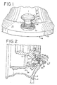
- FIGS. 1 through 3 illustrate a wheel hub stress reduction system 10 provided for reference purposes only.
- system 10 includes a roughly bell-shaped wheel hub 12 having a barrel portion which attaches to an axle by bearings (not shown).
- a wheel bolt 20 is illustrated with the shank 22 having a serrated shoulder 24 at one end, and a threaded portion 25 at an opposing end.
- the serrated shoulder 24 may be press fit into a cylindrical hole 14 of the hub mounting flange 15.
- the bolt shank 22 extends through a hole 26 defined by the brake drum G and a hole 28 defined by wheel W.
- a wheel nut L threadably engages the bolt threaded portion 25 to mount the tire T on hub 12.
- the bolt 20 has a head 30 with an undersurface 32 serving as a contact surface which has a contour centered about a longitudinal axis. 34 of the bolt.
- Typically a plurality of holes 14 are equally spaced around the periphery of the hub mounting flange 15, each receiving a bolt 20, with the number of bolts depending upon the load rating of the vehicle.
- the hub mounting flange 15 defines a head seat 35 having a diameter greater than the cylindrical hole 14.
- the illustrated seat 35 has a contour which mates the bolt head undersurface 32, here shown as mating tapered or frusto-conical (also known as a "frustum” or “frustrum”) shapes.
- the bolt head undersurface 32 has an angle ⁇ ("phi") with respect to the bolt longitudinal axis 34, as indicated between the dashed lines 34 and 36, with dashed line 36 indicating a slope angle of the head undersurface 32 and head seat 35.
- this slope angle labeled ⁇ ("phi") is about 45°, although any angle selected in the range of 20° to 80° may be used.
- the effect on performance of using the illustrated tapered head 32 and tapered seat 35 is discussed below with respect to FIG. 6 .
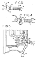
- FIGS. 4 and 5 illustrate an embodiment of a connector 40 according to the present invention.
- the connector 40 includes a hub bolt or bolt 41 having a shank 42.
- the shank 42 has a non threaded portion 44 at one end which may be optionally serrated to carry a plurality of serrations 45, and a threaded portion 46 at the opposing end.
- the bolt 41 has a longitudinal axis 48 upon which is centered a head 50 having an undersurface 52.
- the bolt head undersurface 52 has an angle ⁇ ("theta") with respect to the longitudinal axis 48, as indicated between dashed lines 48 and 54, with the dashed line 54 being coplanar with undersurface 52.
- angle ⁇ is about 90° so the head undersurface 52 is substantially perpendicular to the longitudinal axis 48, as is illustrated for the prior art bolt B of FIG. 8 discussed in the Background section above.
- the connector 40 includes a spacer member or washer 55 preferably sized to seat against the entire undersurface 52 of bolt head 50.
- the washer 55 has a triangular cross-section, illustrated as a right triangle to fit adjacent the mutually perpendicular interface of the head undersurface 52 and the periphery of shoulder 44.
- a remaining exposed surface 56 of washer 55 serves as a contact surface for connector 40.
- the contact surface 56 is selected to be at angle ⁇ ("phi") with respect to the longitudinal axis 48, as indicated in FIG. 4 between dashed lines 48 and 58.
- the angle ⁇ may be selected as described above with respect to bolt 20 of FIGS. 1-3 , allowing connector 40, comprising bolt 41 and washer 55, to be substituted for bolt 20.
- the connector 40 may be constructed in a variety of different ways.
- bolt 41 may be formed by cold heading or otherwise forming shoulder 44 and head 50 preferably from a steel material.
- the spacer member or washer 55 may be formed from a steel material in a stamping operation or other forming operation.
- the bolt 41 is formed by cold heading and washer 55 is formed by stamping.
- the washer 55 is mounted on the bolt shank 42 and seated against the head undersurface 52.
- the washer 55 may be held in place in a variety of different ways, yielding what is known as a captured washer.
- the serrations 45 may be formed on shoulder 44.
- the ridges of serrations 45 provide shank 41 with an outer diameter which is greater than the outer diameter of shoulder 44, and greater than the inner diameter of washer 55 to secure the washer to bolt 41.
- the threads 46 may be formed on shank 41 either before, after, or during formation of the serrations 45.
- the washer 55 may be compressed or pre-loaded to secure the washer against the head undersurface 52.
- serrations 45 and threads 46 may be formed either before or after washer 55 is installed on bolt 41.
- FIG. 5 illustrates an embodiment of a wheel hub stress reduction system 60 according to the present invention employing a connector 40.
- the connector 40 is substituted for bolt 20 to couple together hub 12, brake housing G, and wheel W, using wheel nut L to mount a tire T on a vehicle.
- the interface surface 56 of washer 55 rests against the tapered head seat 35.
- washer 55 in connector 40 which moves or floats on a shank shoulder 44, which allows connector 40 to compensate for nonconcentricities of either the bolt head 50 or the cylindrical hub hole 14.
- the captured washer 55 promotes full contact of the seating surfaces 52 and 55 at all times during tightening of the wheel nut L.
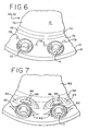
- FIGS. 6 and 7 are stress diagrams comparing the tensile stress imparted to a wheel hub 15 using either wheel hub stress reduction system 10 or 60 ( FIG. 6 ), with the tensile stress imparted to a wheel hub H using the prior art system discussed in the Background Section ( FIG. 7 ) for one specific case.
- FIG. 7 represents a typical case, and it has been found that the results are similar for other hub shapes.
- FIG. 6 illustrates a stress pattern 70 produced by stress reduction system 10 or 60.
- the stress pattern 70 shows different stress levels 72, 74, 75, 76 and 78, representing increasing levels of stress.
- FIG. 7 illustrates a stress pattern 80 on hub H produced by prior art bolts B.
- the stress pattern 80 shows different stress levels 82, 84, 85, 86 and 88 which represent increasing levels of stress.
- FIGS. 6 and 7 do not address the fatigue or cyclic stresses, only the mean tensile stress generated by tightening wheel nut L when mounting tire T on a vehicle.
- the prior art stress pattern of FIG. 7 shows regions of little or no stress in the barrel portion 82 of the generally bell-shaped hub H, and in pairs of triangular shaped regions extending from opposing sides of each bolt hole C.
- regions of extremely high stress 86 and 88 occurred tangentially along the inboard portion of each of bolt holes C.
- Transitional regions of stress 84 and 85 lie between the extremely high stress regions 86, 88 and the little or no stress regions 82.
- FIG. 6 also has regions of little or no stress in the barrel portion of hub 12 and extending circumferentially between each of the bolt holes 14.
- the highest areas of stress 78 are pairs of small diamond shaped regions located on opposing sides of each hole 14 and lying in an annular band region encircling hub 12. Transitional regions of stress 74, 75 and 76 lie between stress regions 72 and 78.
- the highest levels of tensile stress 78 in stress reduction systems 10, 60 are roughly half of the highest stress levels 86, 88 experienced using a prior art hub H and bolt B design.
- the location of the highest stress levels is vastly improved using stress reduction systems 10, 60 over that of the prior art hub H and bolt B assembly of FIGS. 7 and 8 .
- the extremely high tensile stress 86, 88 occurs in a critical region of the hub H. This critical region is located along a curved transition between mounting flange D and the barrel portion of hub H, and at locations inboard from where material has been removed to form the holes C. The curved transition and the material removal each inherently weaken the hub in the critical region.
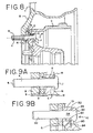
- FIG. 9A shows the resultant tensile stress as vector R imparted by the flat undersurface N and bolt head J in a radial direction.
- FIG. 9B illustrates the effect of using a contoured seat 35 with a contoured contact surface 32 or 56, but for simplicity only system 10 is illustrated.
- the contoured seat 35 is assumed to be in full contact with the bolt head contact surface 32 or 56.
- the total force imparted by bolt head 30 is represented by a vector 90 having a direction which is normal to, or perpendicular to, the contoured seat 32.
- the wheel nuts L in FIGS. 9A and 9B are each tightened with the same torque, the magnitude of the forces represented by vector S and vector 92 are equal, and thus, vectors S and 92 have the same length.
- Each head has an exposed surface which projects beyond said hub interior surface. As seen in FIG.
- each head seat has a first diameter at the interior surface and each head may have a second diameter greater than the first diameter wherein each head has an exposed surface which projects beyond said hub interior surface.
- each of the holes 14 has a first circumference
- each seating surface 35 has a second circumference greater than the first circumference
- each head contact surface 32 or 56 has a third circumference sized for a contact fit with said second circumference of said associated hub seating surface 35 when tightened by said wheel nut.
- the first diameter may be greater than the second diameter wherein the head has an exposed surface between the hub interior surface and hub exterior surface.
- the exposed surface is recessed below the hub interior surface.
- vector 90 has a vertical component shown as vector 92 and a horizontal component shown as vector 94.
- the terms “horizontal” and “vertical” are relative terms with respect to the view of FIG. 9B . These results were verified by the test data shown in FIGS. 6 and 7 for the maximum stress levels 78 and 86, 88, respectively.
- the horizontal stress vector 94 may impart a residual compressive stress in the critical region of hub 12.
- the horizontal stress vector 94 may also be responsible for moving the location of the highest stress levels 86, 88 in FIG. 7 to the location of the highest stress levels 78 in FIG. 6 , which is out of a critical region.
- the tensile stress reduction systems 10, 60 use a shape where the stud head 30, 50 is an angular design or taper that is seated in a countersunk hole 14, 35.
- This concept produces a lower tensile stress 78 in the critical region of the hub 12 because the forces from the stud mounting torque are directed normal to the connector contact surface 32, 56, instead of perpendicular to the prior art head undersurface N.
- This normal direction of the force indicated by vector 90 lowers the mean tensile force of the prior art system, indicated by the vector R, and may impart a residual compressive stress indicated by vector 94 in the critical region of hub 12.
- the shape of connector 20 has benefit as a monolithic one piece stud design.
- the two-piece assembled design 40 comprising stud 42 with captured washer 55 promotes full contact of contact surfaces 32, 56 with the contoured seat 32 at all times during tightening.
Claims (13)
- Radnabenspannungsminderungssystem (10) zum Festhalten eines Rads (W) an einem Fahrzeug unter Verwendung von Radmuttern (L), umfassend:eine Nabe (12) mit einem Befestigungsteil (15), der mehrere Löcher (14) definiert, die einen ersten Umfang aufweisen; undmehrere Gewindeverbinder (40), die jeweils durch eines der Löcher (14) aufgenommen werden;wobei:der Nabenbefestigungsteil (15) eine Innen- und eine Außenfläche (16, 18) umfasst, die einander gegenüberliegen und mehrere sich dazwischen erstreckende Löcher (14) aufweisen; undjeder Gewindeverbinder (40) einen Kopf (50), der an der Nabeninnenfläche (16) festgehalten wird, und einen mit einem Gewinde versehenen Teil (46), der sich über die Nabenaußenfläche (18) hinaus erstreckt, um die Radnabe (L) in Eingriff zu nehmen, umfasst;die Nabeninnenfläche (16) eine konturierte Sitzfläche (35) definiert, die einen zweiten Umfang an der Nabeninnenfläche (16) aufweist, der größer ist als der erste Umfang, wobei sich der Umfang der Sitzfläche (35) zwischen dem ersten und dem zweiten Umfang allmählich verjüngt; undjeder Verbinder (40) einen länglichen Schaft (42) umfasst, der den an einem Ende ausgebildeten Kopf (50) und einen mit einem Gewinde versehenen Teil (46) an einem gegenüberliegenden Ende des Schafts umfasst, wobei der Schaft (42) einen Schulterteil (44) neben dem Kopfteil aufweist, wobei die Außenfläche des Schulterteils mehrere daran ausgebildete Kerbverzahnungen (45) aufweist;wobei die Kerbverzahnungen (45) eine Presspassung mit den Nabenlöchern (14) bei Einführung dort hinein bilden;dadurch gekennzeichnet, dassjeder Verbinder (40) ein Abstandselement (55) umfasst, das den Schaft (42) neben dem Kopf (50) umgibt, wobei eine freiliegende Fläche des Abstandselements (55) eine Kontaktfläche (56) bereitstellt, die konturiert ist, um bei Festziehen durch die Radmutter (L) an einer zugehörigen Nabensitzfläche (35) anzuliegen, wobei sich der Umfang der Kontaktfläche (56) bei Festziehen durch die Radmutter (L) für einen Kontaktsitz mit der zugehörigen sich verjüngenden Nabensitzfläche (35) allmählich verjüngt, um einen Bereich mit maximaler Zugspannung in der Nabe (12) zu erzeugen, wenn die Gewindeverbinder (40) durch eine Radmutter (L), die mit ihm in Gewindeeingriff steht, angezogen werden, wobei der Bereich mit maximaler Zugspannung hinter einem Nabenradius liegt, der das eine der Löcher (14) halbiert.
- System nach Anspruch 1, wobei:sich das Abstandselement (55) neben einer Unterseite (52) des Kopfs (50) befindet; unddie Kerbverzahnungen (45) das Abstandselement (55) neben der Kopfunterseite (52) befestigen.
- System (10) nach Anspruch 1, wobei:die Kopfsitze (35) jeweils von der Innenfläche (16) ausgespart sind und ein zugehöriges Loch (14) der mehreren Löcher (14) umgeben; unddie mehreren Verbinder (40) jeweils mit Presspassung in ein zugehöriges Loch (14) der mehreren Löcher (14) eingepasst sind, wobei jeder Verbinder (40) einen mit einem Gewinde versehenen Teil (46), der sich über die Außenfläche (18) hinaus erstreckt, um eine Radmutter (L) in Eingriff zu nehmen, und eine Kontaktfläche (56),die unter der Innenfläche (16) ausgespart ist, aufweist, wobei die Kontaktfläche (56) an dem Kopfsitz (35) anliegt.
- System nach Anspruch 1, wobei:jedes Loch (14) einen ersten Umfang aufweist;jeder zugehörige Kopfsitz (35) einen zweiten Umfang aufweist, der größer ist als der erste Umfang; undjede freiliegende Abstandselementkontaktfläche (56) einen dritten Umfang aufweist, der zum Zusammenfügen mit dem Kopfsitz (35) am zweiten Umfang ausgewählt ist.
- System nach Anspruch 4, wobei:sich der Umfang jedes Kopfsitzes (35) zwischen dem ersten und dem zweiten Umfang verjüngt; undjede freiliegende Abstandselementkontaktfläche (56) eine sich verjüngende Kontaktfläche aufweist.
- System nach einem der Ansprüche 3 bis 5, wobei:jeder Kopfsitz (35) eine kegelstumpfförmige Aussparung umfasst, die sich von der Innenfläche (16) zu dem zugehörigen Loch (14) verjüngt; und jede Kontaktfläche (56) des Verbinders (40) eine Kegelstumpfform umfasst.
- System nach einem der Ansprüche 3 bis 6, wobei:jeder Kopfsitz (35) einen ersten Durchmesser an der Innenfläche (16) aufweist; undjeder Kopf (50) einen zweiten Durchmesser aufweist, der größer ist als der erste Durchmesser.
- System nach einem der Ansprüche 3 bis 7, wobei:jeder Kopf (50) eine freiliegende Fläche zwischen der Nabeninnenfläche (16) und der Außenfläche (18) aufweist.
- Verfahren zur Minderung von Spannung an einer Radnabe (12), die unter Verwendung von Radmuttern (L) ein Rad (W) an einem Fahrzeug festhält, umfassend:Ausbilden mehrerer Löcher (14) durch einen Befestigungsteil (15) der Radnabe (12), wobei jedes der mehreren Löcher (14) einen ersten Umfang aufweist;Ausbilden einer konturierten Sitzfläche (35) für jedes zugehörige Loch (14), wobei jede Sitzfläche (35) einen zweiten Umfang an der Nabeninnenfläche (16) aufweist, der größer ist als der erste Umfang und sich zwischen dem ersten und dem zweiten Umfang allmählich verjüngt; dadurch gekennzeichnet, dass das Verfahren weiterhin die folgenden Schritte umfasst:Einführen eines mehrerer Gewindeverbinder (40) durch ein zugehöriges Loch (14) der mehreren Löcher (14), wobei jeder Verbinder (40) ein Abstandselement (55) mit einer Kontaktfläche (56) enthält, deren Umfang sich für einen Kontaktsitz mit der Sitzfläche (35) des zugehörigen Lochs (14) beim Festziehen durch eine Radmutter (L) allmählich verjüngt;Anziehen jedes eingeführten Verbinders (40) mit einer damit in Gewindeeingriff stehenden Radmutter (L);Anordnen der sich verjüngenden Kontaktfläche (56) jedes eingeführten Verbinders (40) und des Abstandselements (44) an der konturierten Sitzfläche (35) des zugehörigen Lochs (14), um nach dem Anziehen einen Bereich mit maximaler Zugspannung in der Nabe (12) zu erzeugen, wobei der Bereich mit maximaler Zugspannung hinter einem Nabenradius liegt, der das eine der Löcher (14) halbiert.
- Verfahren zur Minderung von Spannung nach Anspruch 9, wobei das Ausbilden Folgendes umfasst:Ausbilden jedes Lochs (14) mit einem ersten Umfang zwischen der Innen- und Außenfläche (16, 18) der Nabe des Befestigungsteils (15); undAusbilden jeder konturierten Sitzfläche (35) neben der Nabeninnenfläche (16) mit einem zweiten Umfang, der größer ist als der erste Umfang und im Wesentlichen konzentrisch dazu verläuft.
- Verfahren zur Minderung von Spannung nach Anspruch 9, wobei:jedes Abstandselement (55) einen Querschnitt in Form eines allgemein rechtwinkligen Dreiecks aufweist, der eine erste Schenkelfläche neben dem Schaft, eine zweite Schenkelfläche neben der Kopfunterseite (52) und eine Hypotenusefläche, die die äußere konturierte Kontaktfläche (56) bildet, umfasst; unddas Ausbilden Konturieren jeder Sitzfläche (35) als eine Kegelstumpfform umfasst.
- Verfahren zur Minderung von Spannung nach Anspruch 11, wobei:jedes Abstandselement (55) einen Querschnitt in Form eines allgemein gleichschenkligen, rechtwinkligen Dreiecks aufweist; unddas Ausbilden Konturieren jeder Sitzfläche (35) als eine rechtwinklige Kegelstumpfform mit einem Winkel von ca. 45° zwischen einer konischen Fläche und einer Basis der Form umfasst.
- Verfahren zur Minderung von Spannung nach einem der Ansprüche 9 bis 12, das weiterhin Konstruieren des Gewindeverbinders (40) umfasst, wobei das Konstruieren Folgendes umfasst:Bereitstellen eines Schafts (42) mit einem ersten und einem zweiten Ende, die sich gegenüberliegen;Ausbilden eines Kopfs (50) an dem ersten Ende des Schafts;Versehen eines Teils des Schafts (42) neben dem zweiten Ende mit einem Gewinde;Versehen des Schafts (42) mit einem Schulterteil (44) neben dem Kopf (50);Anbringen eines Abstandselements (55) an dem Schaft (42) neben dem Kopf (50); undnach dem Anbringen Befestigen des Abstandselements (55) an dem Schaft (42).
Applications Claiming Priority (1)
| Application Number | Priority Date | Filing Date | Title |
|---|---|---|---|
| US11/907,726 US20090096276A1 (en) | 2007-10-16 | 2007-10-16 | Wheel hub stress reduction system |
Publications (2)
| Publication Number | Publication Date |
|---|---|
| EP2052877A1 EP2052877A1 (de) | 2009-04-29 |
| EP2052877B1 true EP2052877B1 (de) | 2012-05-23 |
Family
ID=40225898
Family Applications (1)
| Application Number | Title | Priority Date | Filing Date |
|---|---|---|---|
| EP08251829A Active EP2052877B1 (de) | 2007-10-16 | 2008-05-27 | Spannungsreduzierungssystem für Radnaben |
Country Status (7)
| Country | Link |
|---|---|
| US (2) | US20090096276A1 (de) |
| EP (1) | EP2052877B1 (de) |
| JP (1) | JP2009096467A (de) |
| CN (1) | CN101412345B (de) |
| BR (1) | BRPI0803422A2 (de) |
| CA (1) | CA2636141A1 (de) |
| MX (1) | MX2008012656A (de) |
Families Citing this family (8)
| Publication number | Priority date | Publication date | Assignee | Title |
|---|---|---|---|---|
| JP2011058594A (ja) * | 2009-09-14 | 2011-03-24 | Beta Titanium:Kk | ホイール締結部品 |
| CN102555662A (zh) * | 2011-12-31 | 2012-07-11 | 重庆长安汽车股份有限公司 | 一种车轮安装结构 |
| MX2014000444A (es) * | 2013-01-11 | 2014-08-28 | Webb Wheel Products Inc | Cubo con piloto de tambor. |
| FR3025455B1 (fr) * | 2014-09-08 | 2017-12-15 | Peugeot Citroen Automobiles Sa | Moyeu d’essieu de vehicule a reserve elastique pour la solidarisation d’une roue a voile a zones de passage de vis sensiblement planes |
| JP6359742B1 (ja) | 2017-09-28 | 2018-07-18 | リンテックス株式会社 | 車両用ホイールディスクおよび車両用ディスクホイール |
| US10688825B2 (en) | 2017-10-26 | 2020-06-23 | Consolidated Metco, Inc. | Wheel retention system |
| CN109538615A (zh) * | 2018-12-07 | 2019-03-29 | 保定长安客车制造有限公司 | 一种大锥面车轮螺母的防松防断裂结构 |
| DE102019122279A1 (de) * | 2019-06-04 | 2020-12-10 | Schaeffler Technologies AG & Co. KG | Verbindungselement mit einem Gewinde aufweisenden Verbindungsteil |
Family Cites Families (28)
| Publication number | Priority date | Publication date | Assignee | Title |
|---|---|---|---|---|
| JPS5499201U (de) * | 1977-12-24 | 1979-07-13 | ||
| DE2931400C2 (de) * | 1979-07-31 | 1981-10-01 | Mannesmann Kronprinz Ag, 5650 Solingen | Nutzfahrzeugrad für Einzel- und Zwillingsanordnung |
| JPS59179701U (ja) * | 1983-05-19 | 1984-12-01 | 井関農機株式会社 | 車輪のホイルデイスク |
| US4621961A (en) * | 1985-02-28 | 1986-11-11 | Bulent Gulistan | Captive panel fastener |
| JPH03272828A (ja) * | 1990-03-23 | 1991-12-04 | Honda Motor Co Ltd | 繊維強化複合材の圧縮締結部構造 |
| US5326206A (en) * | 1993-04-19 | 1994-07-05 | Northrop Corporation | Method for compensating for bolt hole misalignment and bolt assemblies therefor |
| US5583983A (en) * | 1994-11-17 | 1996-12-10 | Objectware, Inc. | Multi-platform object-oriented software development and deployment system |
| CZ291096B6 (cs) * | 1995-02-08 | 2002-12-11 | Mannesmann Aktiengesellschaft | Vozidlové kolo a způsob jeho výroby |
| US6149244A (en) * | 1998-05-29 | 2000-11-21 | Consolidated Metco Inc. | Wheel hub assembly and method of installing a hub on an axle |
| IT1305152B1 (it) * | 1998-11-02 | 2001-04-10 | Skf Ind Spa | Viti prigioniere di tipo perfezionato per il collegamento di unaruota e di un elemento frenante al mozzo della ruota di un autoveicolo |
| US6866457B2 (en) * | 2001-04-05 | 2005-03-15 | Industrial And Automotive Fasteners, L.L.C. | Decorative capped wheel nut or bolt assembly and method |
| JP4911333B2 (ja) * | 2001-07-18 | 2012-04-04 | 株式会社ジェイテクト | 車輪用軸受装置における車輪取付け構造 |
| JP4013675B2 (ja) * | 2002-07-16 | 2007-11-28 | 株式会社ジェイテクト | 転がり軸受装置 |
| JP4085888B2 (ja) * | 2003-05-22 | 2008-05-14 | 日産自動車株式会社 | 車軸ユニット |
| JP3905497B2 (ja) * | 2003-06-23 | 2007-04-18 | 株式会社杉浦製作所 | ホイールナット及びホイールボルト |
| CN1576061A (zh) * | 2003-07-25 | 2005-02-09 | Ntn株式会社 | 车轮用轴承装置 |
| US7117322B2 (en) * | 2003-09-08 | 2006-10-03 | International Business Machines Corporation | Method, system, and program for retention management and protection of stored objects |
| US7044563B2 (en) * | 2003-11-07 | 2006-05-16 | Nsk Corporation | Wheel supporting roller bearing unit and manufacturing method of the same |
| JP2005226789A (ja) * | 2004-02-16 | 2005-08-25 | Isuzu Motors Ltd | トルクリミッター付き締結部材 |
| CN100532134C (zh) * | 2004-03-22 | 2009-08-26 | 韦伯车轮产品有限公司 | 具有改良的导向结构的轮毂及其制造方法 |
| US8108429B2 (en) * | 2004-05-07 | 2012-01-31 | Quest Software, Inc. | System for moving real-time data events across a plurality of devices in a network for simultaneous data protection, replication, and access services |
| JP2005324598A (ja) * | 2004-05-12 | 2005-11-24 | Ntn Corp | 車輪用軸受装置およびハブボルト |
| JP4410701B2 (ja) * | 2005-03-01 | 2010-02-03 | 株式会社杉浦製作所 | ホイールボルト及びその製造方法 |
| EP1762401B1 (de) * | 2005-09-07 | 2009-04-22 | Aktiebolaget SKF | Verbesserte Bolzenfestlegung für die Lagerung eines Rads auf einer Radnabe |
| DE102005061389A1 (de) * | 2005-12-22 | 2007-08-23 | Schaeffler Kg | Radnabe mit axialen Ausnehmungen zwischen den Löchern für Radschrauben |
| US8170985B2 (en) * | 2006-01-31 | 2012-05-01 | Emc Corporation | Primary stub file retention and secondary retention coordination in a hierarchical storage system |
| US20090144341A1 (en) * | 2007-12-03 | 2009-06-04 | Apple Inc. | Ad Hoc Data Storage Network |
| US8365241B1 (en) * | 2008-06-09 | 2013-01-29 | Symantec Corporation | Method and apparatus for archiving web content based on a policy |
-
2007
- 2007-10-16 US US11/907,726 patent/US20090096276A1/en not_active Abandoned
-
2008
- 2008-05-27 EP EP08251829A patent/EP2052877B1/de active Active
- 2008-06-18 CN CN200810128920.6A patent/CN101412345B/zh active Active
- 2008-06-25 CA CA002636141A patent/CA2636141A1/en not_active Abandoned
- 2008-07-10 BR BRPI0803422-2A patent/BRPI0803422A2/pt not_active Application Discontinuation
- 2008-10-01 MX MX2008012656A patent/MX2008012656A/es active IP Right Grant
- 2008-10-15 JP JP2008266741A patent/JP2009096467A/ja active Pending
-
2010
- 2010-08-16 US US12/806,526 patent/US20100308643A1/en not_active Abandoned
Also Published As
| Publication number | Publication date |
|---|---|
| CA2636141A1 (en) | 2009-04-16 |
| CN101412345A (zh) | 2009-04-22 |
| US20100308643A1 (en) | 2010-12-09 |
| BRPI0803422A2 (pt) | 2009-11-17 |
| JP2009096467A (ja) | 2009-05-07 |
| EP2052877A1 (de) | 2009-04-29 |
| US20090096276A1 (en) | 2009-04-16 |
| CN101412345B (zh) | 2010-11-03 |
| MX2008012656A (es) | 2009-05-08 |
Similar Documents
| Publication | Publication Date | Title |
|---|---|---|
| EP2052877B1 (de) | Spannungsreduzierungssystem für Radnaben | |
| US4717299A (en) | Wheel nut assemblies | |
| US4958944A (en) | Bearing for wheel mount | |
| US20020012486A1 (en) | Wheel-support rolling bearing unit and a method manufacturing the same | |
| JP3902708B2 (ja) | トルク角制限ホイールナット | |
| US20230391139A1 (en) | Reusable rim for non-pneumatic tires | |
| EP2666647A1 (de) | Kugellagervorrichtung für ein fahrzeugrad | |
| US8469461B2 (en) | Universal wheel hub | |
| JP4628766B2 (ja) | 車輪用軸受装置 | |
| EP3324059B1 (de) | Mutternsicherungssystem | |
| CN104669929A (zh) | 一种改进的分体式车轮 | |
| EP3715244B1 (de) | Schraubverbindung für radanordnungen | |
| AU2018355420B2 (en) | Wheel retention system | |
| JP2006076346A (ja) | 車輪用軸受装置 | |
| US20040070260A1 (en) | Wheel hub assemblies | |
| EP1844951A1 (de) | Selbstverriegelender Nippel und Radspeiche | |
| JP3434618B2 (ja) | 大、中型軽合金ホイール | |
| JP2006118548A (ja) | 車輪用軸受装置 | |
| JP2006001414A (ja) | 牽引車用車輪および牽引車 | |
| MXPA00010664A (en) | Dual wheel mounting system |
Legal Events
| Date | Code | Title | Description |
|---|---|---|---|
| PUAI | Public reference made under article 153(3) epc to a published international application that has entered the european phase |
Free format text: ORIGINAL CODE: 0009012 |
|
| AK | Designated contracting states |
Kind code of ref document: A1 Designated state(s): AT BE BG CH CY CZ DE DK EE ES FI FR GB GR HR HU IE IS IT LI LT LU LV MC MT NL NO PL PT RO SE SI SK TR |
|
| AX | Request for extension of the european patent |
Extension state: AL BA MK RS |
|
| 17P | Request for examination filed |
Effective date: 20091007 |
|
| 17Q | First examination report despatched |
Effective date: 20091105 |
|
| AKX | Designation fees paid |
Designated state(s): AT BE BG CH CY CZ DE DK EE ES FI FR GB GR HR HU IE IS IT LI LT LU LV MC MT NL NO PL PT RO SE SI SK TR |
|
| GRAP | Despatch of communication of intention to grant a patent |
Free format text: ORIGINAL CODE: EPIDOSNIGR1 |
|
| GRAS | Grant fee paid |
Free format text: ORIGINAL CODE: EPIDOSNIGR3 |
|
| GRAA | (expected) grant |
Free format text: ORIGINAL CODE: 0009210 |
|
| AK | Designated contracting states |
Kind code of ref document: B1 Designated state(s): AT BE BG CH CY CZ DE DK EE ES FI FR GB GR HR HU IE IS IT LI LT LU LV MC MT NL NO PL PT RO SE SI SK TR |
|
| REG | Reference to a national code |
Ref country code: GB Ref legal event code: FG4D |
|
| REG | Reference to a national code |
Ref country code: CH Ref legal event code: EP |
|
| REG | Reference to a national code |
Ref country code: AT Ref legal event code: REF Ref document number: 558895 Country of ref document: AT Kind code of ref document: T Effective date: 20120615 |
|
| REG | Reference to a national code |
Ref country code: IE Ref legal event code: FG4D |
|
| REG | Reference to a national code |
Ref country code: DE Ref legal event code: R096 Ref document number: 602008015827 Country of ref document: DE Effective date: 20120726 |
|
| REG | Reference to a national code |
Ref country code: NL Ref legal event code: VDEP Effective date: 20120523 |
|
| REG | Reference to a national code |
Ref country code: LT Ref legal event code: MG4D Effective date: 20120523 |
|
| PG25 | Lapsed in a contracting state [announced via postgrant information from national office to epo] |
Ref country code: SE Free format text: LAPSE BECAUSE OF FAILURE TO SUBMIT A TRANSLATION OF THE DESCRIPTION OR TO PAY THE FEE WITHIN THE PRESCRIBED TIME-LIMIT Effective date: 20120523 Ref country code: FI Free format text: LAPSE BECAUSE OF FAILURE TO SUBMIT A TRANSLATION OF THE DESCRIPTION OR TO PAY THE FEE WITHIN THE PRESCRIBED TIME-LIMIT Effective date: 20120523 Ref country code: CY Free format text: LAPSE BECAUSE OF FAILURE TO SUBMIT A TRANSLATION OF THE DESCRIPTION OR TO PAY THE FEE WITHIN THE PRESCRIBED TIME-LIMIT Effective date: 20120523 Ref country code: IS Free format text: LAPSE BECAUSE OF FAILURE TO SUBMIT A TRANSLATION OF THE DESCRIPTION OR TO PAY THE FEE WITHIN THE PRESCRIBED TIME-LIMIT Effective date: 20120923 Ref country code: NO Free format text: LAPSE BECAUSE OF FAILURE TO SUBMIT A TRANSLATION OF THE DESCRIPTION OR TO PAY THE FEE WITHIN THE PRESCRIBED TIME-LIMIT Effective date: 20120823 Ref country code: LT Free format text: LAPSE BECAUSE OF FAILURE TO SUBMIT A TRANSLATION OF THE DESCRIPTION OR TO PAY THE FEE WITHIN THE PRESCRIBED TIME-LIMIT Effective date: 20120523 |
|
| REG | Reference to a national code |
Ref country code: AT Ref legal event code: MK05 Ref document number: 558895 Country of ref document: AT Kind code of ref document: T Effective date: 20120523 |
|
| PG25 | Lapsed in a contracting state [announced via postgrant information from national office to epo] |
Ref country code: LV Free format text: LAPSE BECAUSE OF FAILURE TO SUBMIT A TRANSLATION OF THE DESCRIPTION OR TO PAY THE FEE WITHIN THE PRESCRIBED TIME-LIMIT Effective date: 20120523 Ref country code: HR Free format text: LAPSE BECAUSE OF FAILURE TO SUBMIT A TRANSLATION OF THE DESCRIPTION OR TO PAY THE FEE WITHIN THE PRESCRIBED TIME-LIMIT Effective date: 20120523 Ref country code: GR Free format text: LAPSE BECAUSE OF FAILURE TO SUBMIT A TRANSLATION OF THE DESCRIPTION OR TO PAY THE FEE WITHIN THE PRESCRIBED TIME-LIMIT Effective date: 20120824 Ref country code: PT Free format text: LAPSE BECAUSE OF FAILURE TO SUBMIT A TRANSLATION OF THE DESCRIPTION OR TO PAY THE FEE WITHIN THE PRESCRIBED TIME-LIMIT Effective date: 20120924 Ref country code: SI Free format text: LAPSE BECAUSE OF FAILURE TO SUBMIT A TRANSLATION OF THE DESCRIPTION OR TO PAY THE FEE WITHIN THE PRESCRIBED TIME-LIMIT Effective date: 20120523 |
|
| PG25 | Lapsed in a contracting state [announced via postgrant information from national office to epo] |
Ref country code: BE Free format text: LAPSE BECAUSE OF FAILURE TO SUBMIT A TRANSLATION OF THE DESCRIPTION OR TO PAY THE FEE WITHIN THE PRESCRIBED TIME-LIMIT Effective date: 20120523 Ref country code: MC Free format text: LAPSE BECAUSE OF NON-PAYMENT OF DUE FEES Effective date: 20120531 |
|
| REG | Reference to a national code |
Ref country code: CH Ref legal event code: PL |
|
| PG25 | Lapsed in a contracting state [announced via postgrant information from national office to epo] |
Ref country code: NL Free format text: LAPSE BECAUSE OF FAILURE TO SUBMIT A TRANSLATION OF THE DESCRIPTION OR TO PAY THE FEE WITHIN THE PRESCRIBED TIME-LIMIT Effective date: 20120523 Ref country code: RO Free format text: LAPSE BECAUSE OF FAILURE TO SUBMIT A TRANSLATION OF THE DESCRIPTION OR TO PAY THE FEE WITHIN THE PRESCRIBED TIME-LIMIT Effective date: 20120523 Ref country code: CH Free format text: LAPSE BECAUSE OF NON-PAYMENT OF DUE FEES Effective date: 20120531 Ref country code: CZ Free format text: LAPSE BECAUSE OF FAILURE TO SUBMIT A TRANSLATION OF THE DESCRIPTION OR TO PAY THE FEE WITHIN THE PRESCRIBED TIME-LIMIT Effective date: 20120523 Ref country code: DK Free format text: LAPSE BECAUSE OF FAILURE TO SUBMIT A TRANSLATION OF THE DESCRIPTION OR TO PAY THE FEE WITHIN THE PRESCRIBED TIME-LIMIT Effective date: 20120523 Ref country code: SK Free format text: LAPSE BECAUSE OF FAILURE TO SUBMIT A TRANSLATION OF THE DESCRIPTION OR TO PAY THE FEE WITHIN THE PRESCRIBED TIME-LIMIT Effective date: 20120523 Ref country code: LI Free format text: LAPSE BECAUSE OF NON-PAYMENT OF DUE FEES Effective date: 20120531 Ref country code: EE Free format text: LAPSE BECAUSE OF FAILURE TO SUBMIT A TRANSLATION OF THE DESCRIPTION OR TO PAY THE FEE WITHIN THE PRESCRIBED TIME-LIMIT Effective date: 20120523 Ref country code: AT Free format text: LAPSE BECAUSE OF FAILURE TO SUBMIT A TRANSLATION OF THE DESCRIPTION OR TO PAY THE FEE WITHIN THE PRESCRIBED TIME-LIMIT Effective date: 20120523 |
|
| REG | Reference to a national code |
Ref country code: IE Ref legal event code: MM4A |
|
| PG25 | Lapsed in a contracting state [announced via postgrant information from national office to epo] |
Ref country code: PL Free format text: LAPSE BECAUSE OF FAILURE TO SUBMIT A TRANSLATION OF THE DESCRIPTION OR TO PAY THE FEE WITHIN THE PRESCRIBED TIME-LIMIT Effective date: 20120523 Ref country code: IT Free format text: LAPSE BECAUSE OF FAILURE TO SUBMIT A TRANSLATION OF THE DESCRIPTION OR TO PAY THE FEE WITHIN THE PRESCRIBED TIME-LIMIT Effective date: 20120523 |
|
| PLBE | No opposition filed within time limit |
Free format text: ORIGINAL CODE: 0009261 |
|
| STAA | Information on the status of an ep patent application or granted ep patent |
Free format text: STATUS: NO OPPOSITION FILED WITHIN TIME LIMIT |
|
| REG | Reference to a national code |
Ref country code: FR Ref legal event code: ST Effective date: 20130307 |
|
| GBPC | Gb: european patent ceased through non-payment of renewal fee |
Effective date: 20120823 |
|
| PG25 | Lapsed in a contracting state [announced via postgrant information from national office to epo] |
Ref country code: FR Free format text: LAPSE BECAUSE OF NON-PAYMENT OF DUE FEES Effective date: 20120723 Ref country code: ES Free format text: LAPSE BECAUSE OF FAILURE TO SUBMIT A TRANSLATION OF THE DESCRIPTION OR TO PAY THE FEE WITHIN THE PRESCRIBED TIME-LIMIT Effective date: 20120903 Ref country code: IE Free format text: LAPSE BECAUSE OF NON-PAYMENT OF DUE FEES Effective date: 20120527 |
|
| 26N | No opposition filed |
Effective date: 20130226 |
|
| REG | Reference to a national code |
Ref country code: DE Ref legal event code: R097 Ref document number: 602008015827 Country of ref document: DE Effective date: 20130226 |
|
| PG25 | Lapsed in a contracting state [announced via postgrant information from national office to epo] |
Ref country code: GB Free format text: LAPSE BECAUSE OF NON-PAYMENT OF DUE FEES Effective date: 20120823 Ref country code: MT Free format text: LAPSE BECAUSE OF FAILURE TO SUBMIT A TRANSLATION OF THE DESCRIPTION OR TO PAY THE FEE WITHIN THE PRESCRIBED TIME-LIMIT Effective date: 20120523 Ref country code: BG Free format text: LAPSE BECAUSE OF FAILURE TO SUBMIT A TRANSLATION OF THE DESCRIPTION OR TO PAY THE FEE WITHIN THE PRESCRIBED TIME-LIMIT Effective date: 20120823 |
|
| PG25 | Lapsed in a contracting state [announced via postgrant information from national office to epo] |
Ref country code: TR Free format text: LAPSE BECAUSE OF FAILURE TO SUBMIT A TRANSLATION OF THE DESCRIPTION OR TO PAY THE FEE WITHIN THE PRESCRIBED TIME-LIMIT Effective date: 20120523 |
|
| PG25 | Lapsed in a contracting state [announced via postgrant information from national office to epo] |
Ref country code: LU Free format text: LAPSE BECAUSE OF NON-PAYMENT OF DUE FEES Effective date: 20120527 |
|
| PG25 | Lapsed in a contracting state [announced via postgrant information from national office to epo] |
Ref country code: HU Free format text: LAPSE BECAUSE OF FAILURE TO SUBMIT A TRANSLATION OF THE DESCRIPTION OR TO PAY THE FEE WITHIN THE PRESCRIBED TIME-LIMIT Effective date: 20080527 |
|
| REG | Reference to a national code |
Ref country code: DE Ref legal event code: R082 Ref document number: 602008015827 Country of ref document: DE |
|
| PGFP | Annual fee paid to national office [announced via postgrant information from national office to epo] |
Ref country code: DE Payment date: 20230419 Year of fee payment: 16 |