EP2050666B1 - Brennstoffeinfüllstruktur für einen Brennstofftank - Google Patents
Brennstoffeinfüllstruktur für einen Brennstofftank Download PDFInfo
- Publication number
- EP2050666B1 EP2050666B1 EP08161310.1A EP08161310A EP2050666B1 EP 2050666 B1 EP2050666 B1 EP 2050666B1 EP 08161310 A EP08161310 A EP 08161310A EP 2050666 B1 EP2050666 B1 EP 2050666B1
- Authority
- EP
- European Patent Office
- Prior art keywords
- plate portion
- fuel
- level plate
- filler component
- fuel filler
- Prior art date
- Legal status (The legal status is an assumption and is not a legal conclusion. Google has not performed a legal analysis and makes no representation as to the accuracy of the status listed.)
- Not-in-force
Links
Images

Classifications
-
- B—PERFORMING OPERATIONS; TRANSPORTING
- B62—LAND VEHICLES FOR TRAVELLING OTHERWISE THAN ON RAILS
- B62J—CYCLE SADDLES OR SEATS; AUXILIARY DEVICES OR ACCESSORIES SPECIALLY ADAPTED TO CYCLES AND NOT OTHERWISE PROVIDED FOR, e.g. ARTICLE CARRIERS OR CYCLE PROTECTORS
- B62J35/00—Fuel tanks specially adapted for motorcycles or engine-assisted cycles; Arrangements thereof
-
- B—PERFORMING OPERATIONS; TRANSPORTING
- B29—WORKING OF PLASTICS; WORKING OF SUBSTANCES IN A PLASTIC STATE IN GENERAL
- B29C—SHAPING OR JOINING OF PLASTICS; SHAPING OF MATERIAL IN A PLASTIC STATE, NOT OTHERWISE PROVIDED FOR; AFTER-TREATMENT OF THE SHAPED PRODUCTS, e.g. REPAIRING
- B29C49/00—Blow-moulding, i.e. blowing a preform or parison to a desired shape within a mould; Apparatus therefor
- B29C49/20—Blow-moulding, i.e. blowing a preform or parison to a desired shape within a mould; Apparatus therefor of articles having inserts or reinforcements ; Handling of inserts or reinforcements
- B29C2049/2017—Blow-moulding, i.e. blowing a preform or parison to a desired shape within a mould; Apparatus therefor of articles having inserts or reinforcements ; Handling of inserts or reinforcements outside the article
-
- B—PERFORMING OPERATIONS; TRANSPORTING
- B29—WORKING OF PLASTICS; WORKING OF SUBSTANCES IN A PLASTIC STATE IN GENERAL
- B29C—SHAPING OR JOINING OF PLASTICS; SHAPING OF MATERIAL IN A PLASTIC STATE, NOT OTHERWISE PROVIDED FOR; AFTER-TREATMENT OF THE SHAPED PRODUCTS, e.g. REPAIRING
- B29C49/00—Blow-moulding, i.e. blowing a preform or parison to a desired shape within a mould; Apparatus therefor
- B29C49/20—Blow-moulding, i.e. blowing a preform or parison to a desired shape within a mould; Apparatus therefor of articles having inserts or reinforcements ; Handling of inserts or reinforcements
- B29C2049/2021—Inserts characterised by the material or type
- B29C2049/2047—Tubular inserts, e.g. tubes
Definitions
- the present invention relates to a resin fuel tank used in a motorcycle and the like, and more particularly, to a fuel filler structure of the resin fuel tank.
- a fuel tank molded entirely of a resin, and having a metallic level plate inserted in a fuel filler thereof is publicly known.
- a metallic level plate in a fuel filler made of a resin improves toughness against falling down, but requires a structure for preventing looseness or fuel leakage.
- the structure for preventing fuel leakage requires, in addition to a packing of a fuel cap, a dedicated seal to be provided between a level plate and an upstanding portion, as well as a pressing cap for fixing the level plate. This results in an increase in the number of components and complicated structure. Also, since the level plate is provided separately from the upstanding portion, precise positioning of the level plate is burdensome. An object of the present invention is to solve such problem.
- An aspect of the present invention is a fuel filler structure of a fuel tank, including: an upstanding portion provided integrally to a resin fuel tank molded by blow molding, the upstanding portion standing upright in a cylindrical form; and a fuel filler provided in the upstanding portion.
- the fuel filler structure is further defined in that the upstanding portion is formed by insert molding of a separate fuel filler component in an integral manner at the time of the blow molding of the tank, and the fuel filler component integrally includes a level plate portion extending downward below an upper surface of the tank.
- the fuel filler component is fabricated of a resin material by injection molding, and a metallic ring is cast into the fuel filler component during the injection molding.
- the fuel filler component integrated with the level plate portion is formed in advance separately from the fuel tank.
- the fuel filler component is integrated into the inside of the upstanding portion by insert molding at the time of molding the fuel tank. Accordingly, the need for a pressing cap for securing, and a seal is eliminated.
- This allows the level plate to be formed in a simple structure with no looseness occurring, as well as achieves precise positioning of the level plate.
- the metallic ring is inserted into the fuel filler component, thereby enhancing toughness against falling down.
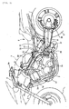
- Fig. 1 is a side view of a motorcycle provided with a fuel tank according to the present invention.
- a power unit 3 is disposed between a front wheel 1 and a rear wheel 2 and supported by a vehicle body frame 4.
- Reference numeral 5 denotes a front fork
- 6 denotes a handlebar
- 7 denotes a tank cover
- 8 denotes a seat
- 9 denotes a rear arm.
- Grips 6a of the handlebar 6 are located above the top of the tank cover 7, and extend long rearward to reach positions above the bank space between a front cylinder 3a and a rear cylinder 3b.
- the vehicle body frame 4 includes: a head pipe 10 supporting the front wheel 1 with the front fork 5 in between; main pipes 11 extending rearward above the power unit 3 from the head pipe 10; center pipes 12 disposed vertically behind the power unit 3; down pipes 13 extending downward in front of the power unit 3 from the head pipe 10; and lower pipes 14 disposed in the front-rear direction below the power unit 3. These pipes are continuously connected with each other so as to form a loop in which the power unit 3 is supported.
- Seat rails 15 extend rearward, and substantially horizontally, each from a vicinity of the connecting portion of the main pipe 11 and the center pipe 12.
- the vehicle body frame 4 is provided with back stays 16 connecting obliquely between the center pipes 12 and the seat rails 15.
- the front fork 5 is rotatably supported by the head pipe 10.
- the main pipes 11 are connected at the front end portions thereof to the head pipe 10, while the down pipes 13 are connected at the upper end portions thereof to the head pipe 10.
- An air cleaner 17 is supported, behind the head pipe 10, and in vicinities of the front end portions of the main pipes 11.
- a first fuel tank 20 is supported, behind the air cleaner 17, by the intermediate portions, in the front-rear direction, of the main pipes 11, and by the front portions of the seat rails 15.
- a second fuel tank 21 is supported by the seat rails 15 behind and below the first fuel tank 20.
- the second fuel tank 21 is housed in a space surrounded by the center pipes 12, the seat rails 15, and the back stays 16.
- the front portion of the second fuel tank 21 vertically overlaps a part of the first fuel tank 20.
- Each center pipe 12 is provided with, at a shoulder portion in an upper portion thereof, a stay 22 projecting upward and rearward, the shoulder portion being in a vicinity of a part at which the center pipe 12 is bent forward to be connected with the main pipe 11.
- a cushion unit 23 constituting a rear suspension is supported, at the upper portion thereof, by the stay 22.
- the stay 22 is disposed to be offset to the left of the vehicle body.
- the cushion unit 23 is slanted downward and extends rearward on the left side of the vehicle body, and is supported, at the lower end portion thereof, by the intermediate portion of the rear arm 9.
- the power unit 3 includes a water-cooled, four-cycle, V engine having the front cylinder 3a and the rear cylinder 3b.
- the first fuel tank 20 is located above the rear-bank cylinder 3b.
- a radiator 24 is supported by the down pipes 13.
- Reference numeral 25 denotes a pivot shaft, which is provided at the intermediate portions, in the vertical direction, of the center pipes 12.
- the rear arm 9 is vertically swingably supported, at the front end portion thereof, by the pivot shaft 25 provided at the intermediate portions, in the vertical direction, of the center pipes 12.
- the rear arm 9 supports, only at the right side of the rear end portion thereof, the rear wheel 2, like a cantilever.
- the drive system of the rear wheel 2 is a shaft drive system.
- the rotational output of the power unit 3 is transmitted via a shaft drive mechanism 27 to a gear box 28 formed in a left portion of the rear end portion of the rear arm 9, so that the rear wheel 2 rotates.
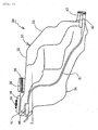
- Fig. 2 is a side view of the first fuel tank 20
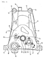
- Fig. 3 is a plan view thereof.
- the first fuel tank 20 is wholly formed by blow molding using an appropriate thermoplastic resin made of polyethylene or the like, and has a hollow main body 30 and a flange 31 formed on, and project from, all the periphery of the side surface of the main body 30.
- the main body 30 includes, in the upper portion thereof, a flat portion 32 and a back face portion 33 slanted downward, and includes, in the lower portion thereof, a bottom portion 34 slanted downward substantially as a whole.
- a cylindrical upstanding portion 35 is formed integrally at the center of the flat portion 32.
- the upstanding portion 35 has a male thread 36 formed therearound, and has the upper end portion opened to serve as an opening portion 37 of a fuel filler (see Fig. 3 ).
- a breather portion 38 is provided on the right side of the front portion of the flat portion 32, and has a breather tube 39 projecting to the left of the vehicle body.
- a nozzle 40 projecting rearward is integrally formed behind the breather portion 38, and to the right of the upstanding portion 35.
- the nozzle 40 is an air bleed hole and communicates with the second fuel tank 21 via an unillustrated tube.
- a mounting hole 41 for mounting a fuel sensor (not illustrated) is provided in the left side of the front portion of the flat portion 32 and has a mounting seat 42 provided therearound, on which the unillustrated fuel sensor is mounted.
- the main body 30 has a pipe 43 formed to project rearward at the rear end portion thereof, and connected with the second fuel tank 21 with an unillustrated hose so as to allow the fuel in the first fuel tank 20 to be dropped into the second fuel tank 21.
- the flange 31 provided around the main body 30 has front and rear, right and left corner portions projecting outward to form front mounting portions 44 and rear mounting portions 45.
- the front mounting portions 44 are bolted, with oval holes 46 formed therein, to the upper surfaces of the main pipes 11, while the rear mounting portions 45 are bolted, with circular holes 47 formed therein, to the upper surfaces of the front portions of the seat rails 15 for installation on the frame.
- the mounting of the first fuel tank 20 is adjusted with the front mounting portions 44.
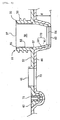
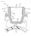
- Fig. 4 shows an enlarged cross-sectional view of the fuel filler part with a fuel cap 50 attached thereto.
- Fig. 5 shows a cross-sectional view taken along the line 5-5 in Fig. 3 .
- Fig. 6 shows a fuel filler component in blow-molding.
- the upstanding portion 35 is formed of a fuel filler component 51 integrally formed with the flat portion 32. In other words, a portion protruding upward from the flat portion 32 of the fuel filler component 51 serves as the upstanding portion 35.
- the fuel filler component 51 is formed by injection molding or the like using polyethylene resin or the like in advance separately from the fuel tank.
- a plate portion 52 forming a part of the flat portion 32 is integrally formed on the side surface of the fuel filler component 51, and extends substantially horizontally.
- a part, located below the plate portion 52, of the fuel filler component 51 forms a level plate portion 53 extending downward while being tapered downward.
- a lower opening 54 is formed in the lower end portion of the level plate portion 53 so as to communicate with the inside of the first fuel tank 20.
- a cylindrical member 55 made of an appropriate metal such as iron is integrated on the inner circumferential side of the fuel filler component 51 by insert molding.
- the cylindrical member 55 has a cylindrical shape being tapered downward, and upper and lower opening edges thereof are rolled outward to form opening portions 56, 57.
- the opening portions 56 and 57 bite into the thick wall of the fuel filler component 51, thereby reinforcing the integration of the fuel filler component 51 and the cylindrical member 55.
- the cylindrical member 55 is exposed at the intermediate portion thereof on the inner circumferential surface of the fuel filler component 51.
- the fuel filler component 51 has a hole penetrating therethrough in the axial direction thereof. The hole forms a fuel filler 58 and the upper end portion of the hole forms the opening portion 37 of the fuel filler.
- a part, below the plate portion 52, of the fuel filler component 51 is integrated with an upper wall 60 of the first fuel tank 20.
- the upper wall 60 underlies the plate portion 52 and forms the flat portion 32 together with the plate portion 52.
- a part of the upper wall 60 forms an outer level plate portion 61 overlapping the outer side of the level plate portion 53.
- the level plate portion 53 and the outer level plate portion 61 are integrated to form a level plate 70.
- a lower opening 62 is formed in the lower end portion of the outer level plate portion 61. The lower opening 62 is closed immediately after the blow molding, and the closed part is cut off together with a bottom portion, which is also closed, of the fuel filler component 51, so that the lower openings 54 and 62 are simultaneously formed.
- a male thread 63 is formed on a part, above the plate portion 52, of the fuel filler component 51, that is, on the outer circumferential part of the upstanding portion 35.
- An outer cylindrical portion 64 of the fuel cap 50 overlaps the outer side of the upstanding portion 35, so as to be fastened with a female thread 65 formed on the inner circumferential surface of the outer cylindrical portion 64.
- the upper portion of the outer cylindrical portion 64 forms a ceiling portion 66 where an inner cylindrical portion 67, which is inserted into the fuel filler 58, is integrally formed.
- a packing 68 is disposed in a region surrounded by the ceiling portion 66 and the outer cylindrical portion 64, so that the opening portion 56 of the cylindrical member 55 is in contact with the packing 68 for sealing. In this way, a gap between the ceiling portion 66 and the upper end of the upstanding portion 35 is sealed.
- Reference numeral 69 denotes a vent hole.
- the plate portion 52 is integrated with the mounting seat 42 and the mounting hole 41 for mounting the fuel sensor.
- the mounting seat 42 is provided to surround the mounting hole 41 for the fuel sensor, and integrated with an insert nut 71 provided therein by insert molding.
- the upper wall 60 overlaps, and is integrated with, a part, where the mounting hole 41 is provided, of the plate portion 52 from below.
- An opening 72 matching the mounting hole 41 is formed at the position, corresponding to the mounting hole 41, in the upper wall 60 so as to be integrated with the mounting hole 41.
- Reference symbol H in the figure indicates the height of the level plate 70, while the horizontal line L at the lower end portion of the outer level plate portion 61 indicates the fluid level at the time when the fuel tank is filled up.
- Fig. 6 is a view for describing the insert molding for the upstanding portion 35.
- the fuel filler component 51 is set in an unillustrated mold in advance, and then, a parison 73 is expanded in the mold. A part of the expanded parison 73 thus overlaps the outer side of the level plate portion 53 so as to be tightly integrated with, the outer side, as the outer level plate portion 61.
- the level plate portion 53 has no opening portion formed at a bottom portion 54a thereof.
- the outer level plate portion 61 integrated after the blow molding is also integrate with a bottom portion 62a which corresponds to the lower opening 62 and which is cut off after the blow molding.
- the upper wall 60 overlaps the lower side of the plate portion 52 so as to be tightly integrated with the lower side.
- the mounting hole 41 (see Fig. 5 ) is also not formed.
- the bottom portion 54a of the level plate portion 53 and the bottom portion 62a of the outer level plate 61 which are integrated with each other after the blow molding, are cut off together by blanking or the like, so that the lower openings 54 and 62 are formed.
- the plate portion 52 and the upper wall 60 are cut off together at the portions thereof corresponding to the mounting hole 41 by blanking or the like, so that the mounting hole 41 and the opening 72 are formed (see Fig. 5 ).
- any special fixing member or seal is unnecessary to be provided for the level plate 70.
- the packing 69 provided between the upstanding portion 35 and the fuel cap 50 suffice for sealing, leading to reduction in the number of components, and to a simple structure.
- cylindrical member 55 made of a metal is integrated, by insert molding, in only the part, above the plate portion 52, of the fuel filler component 51 corresponding to the upstanding portion 35. Accordingly, the toughness against falling down is improved, as well as the integration by the insert molding prevents looseness from occurring.
Landscapes
- Engineering & Computer Science (AREA)
- Mechanical Engineering (AREA)
- Manufacturing & Machinery (AREA)
- Cooling, Air Intake And Gas Exhaust, And Fuel Tank Arrangements In Propulsion Units (AREA)
- Details Of Rigid Or Semi-Rigid Containers (AREA)
- Blow-Moulding Or Thermoforming Of Plastics Or The Like (AREA)
Claims (7)
- Brennstofftankstruktur, die aufweist:einen Kunstharzbrennstofftank (20), der durch Blasformung geformt ist;einen aufrechten Abschnitt (35), der integriert mit dem Kunstharzbrennstofftank (20) bereitgestellt ist, wobei der aufrechte Abschnitt (35) in einer zylindrischen Form aufrecht steht; undeinen Brennstofffüller (58), der in dem aufrechten Abschnitt (35) bereitgestellt ist, wobeider aufrechte Abschnitt (35) zur Zeit der Blasformung des Brennstofftanks (20) durch Umspritzen einer separaten Brennstofffüllerkomponente (51) in einer integralen Weise ausgebildet wird, unddie Brennstofffüllerkomponente (51) einen Niveauplattenabschnitt (53), der sich von einer oberen Oberfläche des Tanks (20) nach unten erstreckt, integral umfasst,wobei ein Plattenabschnitt (52) auf einer Seitenoberfläche der Brennstofffüllerkomponente (51) integral ausgebildet ist und sich im Wesentlichen horizontal erstreckt, und der Teil, der sich unter dem Plattenabschnitt (52) der Füllerkomponente (51) befindet, den Niveauplattenabschnitt (53) bildet, der sich nach unten erstreckt und sich nach unten verjüngt,dadurch gekennzeichnet, dass ein Teil einer oberen Wand (60) des Brennstofftanks (20) einen äußeren Niveauplattenabschnitt (61) bildet, der nur die Außenseite des Niveauplattenabschnitts (53) überlappt, um fest damit integriert zu sein, wobei der Niveauplattenabschnitt (53) und der äußere Niveauplattenabschnitt (61) integriert sind, um eine Niveauplatte (70) zu bilden, undwobei die obere Wand (60) unter dem Plattenabschnitt (52) liegt und zusammen mit dem Plattenabschnitt (52) einen flachen Abschnitt (32) aus einem hohlen Hauptkörper (30) des Brennstofftanks (20) bildet.
- Brennstofftankstruktur nach Anspruch 1, wobei
die Brennstofffüllerkomponente (51) durch Spritzgießen aus einem Kunstharzmaterial hergestellt ist, und
ein Metallring (55) während des Spritzgießens nur in dem Teil oberhalb des Plattenabschnitts (52) der Brennstofffüllerkomponente (51) entsprechend dem aufrechten Abschnitt (35) in die Brennstofffüllerkomponente (51) gegossen wird. - Brennstofftankstruktur nach Anspruch 2, wobei
der Metallring (55) eine zylindrische Form hat, die sich nach unten verjüngt, und obere und untere Öffnungsränder davon nach außen gerollt sind, um Öffnungsabschnitte (56, 57) zu bilden, wobei die Öffnungsabschnitte (56, 57) in die dicke Wand der Brennstofffüllerkomponente (51) greifen, wodurch die Integration der Brennstofffüllerkomponente (51) und des Metallrings (55) verstärkt wird, wobei der Metallring (55) an seinem Zwischenabschnitt auf der Innenumfangsoberfläche der Brennstofffiillerkomponente (51) freiliegt. - Brennstofftankstruktur nach einem der vorhergehenden Ansprüche, wobei der Plattenabschnitt (52) mit einem Montagesitz (42) und einem Montageloch (41) zum Montieren eines Brennstoffsensors integriert ist,
wobei der Montagesitz (42) derart bereitgestellt ist, dass er das Montageloch (41) für den Brennstoffsensor umgibt, und mit einer Einsatzmutter (71) integriert ist, die durch Umspritzen bereitgestellt wird,
wobei die obere Wand (60) einen Teil des Plattenabschnitts (52), wo das Montageloch (41) bereitgestellt ist, von unten überlappt und damit integriert ist, und
wobei eine Öffnung (72), die zu dem Montageloch (41) passt, an der Position, die dem Montageloch (41) entspricht, in der oberen Wand (60) ausgebildet ist, um mit dem Montageloch (41) integriert zu sein. - Brennstofftankstruktur nach einem der vorhergehenden Ansprüche, wobei nach dem Blasformen eine tiefere Öffnung (54) in dem unteren Endabschnitt des Niveauplattenabschnitts (53) ausgebildet wird und eine tiefere Öffnung (62) in dem unteren Endabschnitt des äußeren Niveauplattenabschnitts (61) ausgebildet wird, um mit dem Inneren des Brennstofftanks (20) in Verbindung zu stehen.
- Verfahren zur Herstellung einer Brennstofftankstruktur, das die folgenden Schritte aufweist:- Härten einer Brennstofffüllerkomponente (51) in einer Form, wobei ein Plattenabschnitt (52) auf der Seitenoberfläche der Brennstofffüllerkomponente (51) integral ausgebildet wird und sich im Wesentlichen horizontal erstreckt, und der Teil, der sich unter dem Plattenabschnitt (52) der Füllerkomponente (51) befindet, integral einen Niveauplattenabschnitt (53) bildet, der sich nach unten erstreckt und sich nach unten verjüngt,- Ausdehnen eines Vorformlings (73) in der Form durch Blasformen des Vorformlings, so dass somit ein Teil des ausgedehnten Vorformlings (73) die Außenseite des Niveauplattenabschnitts (53) überlappt, um als ein äußerer Niveauplattenabschnitt (61) fest mit der Außenseite des Niveauplattenabschnitts (53) integriert zu werden, wobei der äußere Niveauplattenabschnitt (61) ein Teil einer oberen Wand (60) des auf diese Art blasgeformten Kunstharzbrennstofftanks (20) ist und nur die Außenseite des Niveauplattenabschnitts (53) überlappt, wobei der Niveauplattenabschnitt (53) und der äußere Niveauplattenabschnitt (61) integriert sind, um eine Niveauplatte (70) zu bilden, wobei die obere Wand (60) unter dem Plattenabschnitt (52) liegt und zusammen mit dem Plattenabschnitt (52) einen flachen Abschnitt (32) eines hohlen Hauptkörpers (30) des Brennstofftanks (20) bildet, wobei zur Zeit der Blasformung des Brennstofftanks (20) ein aufrechter Abschnitt (35) durch das Umspritzen der getrennten Brennstofffüllerkomponente (51) in einer integralen Weise ausgebildet wird, wobei der aufrechte Abschnitt (35) in einer zylindrischen Form aufrecht steht und ein Brennstofffüller (58) in dem aufrechten Abschnitt (35) bereitgestellt ist,- gleichzeitiges Ausbilden einer tieferen Öffnung (54) in dem unteren Endabschnitt des Niveauplattenabschnitts (53) und einer tieferen Öffnung (62) in dem unteren Endabschnitt des äußeren Niveauplattenabschnitts (61) durch gemeinsames Durchtrennen eines unteren Abschnitts (54a) des Niveauplattenabschnitts (53) und eines unteren Abschnitts (62a) der äußeren Niveauplatte (61), die nach der Blasformung miteinander integriert werden, um mit dem Inneren des Brennstofftanks (20) in Verbindung zu stehen.
- Verfahren nach Anspruch 6, wobei die Brennstofffüllerkomponente (51) vor dem Schritt des Härtens der Brennstofffüllerkomponente (51) in der Form durch Spritzgießen aus einem Kunstharzmaterial hergestellt wird, wobei während des Spritzgießens ein Metallring (55) nur in dem Teil oberhalb des Plattenabschnitts (52) der Brennstofffüllerkomponente (51), der dem aufrechten Abschnitt (35) entspricht, in die Brennstofffüllerkomponente (51) gegossen wird.
Applications Claiming Priority (1)
| Application Number | Priority Date | Filing Date | Title |
|---|---|---|---|
| JP2007273221A JP5005496B2 (ja) | 2007-10-19 | 2007-10-19 | 燃料タンクの注入口構造 |
Publications (2)
| Publication Number | Publication Date |
|---|---|
| EP2050666A1 EP2050666A1 (de) | 2009-04-22 |
| EP2050666B1 true EP2050666B1 (de) | 2015-12-09 |
Family
ID=39869975
Family Applications (1)
| Application Number | Title | Priority Date | Filing Date |
|---|---|---|---|
| EP08161310.1A Not-in-force EP2050666B1 (de) | 2007-10-19 | 2008-07-29 | Brennstoffeinfüllstruktur für einen Brennstofftank |
Country Status (5)
| Country | Link |
|---|---|
| US (1) | US20090101642A1 (de) |
| EP (1) | EP2050666B1 (de) |
| JP (1) | JP5005496B2 (de) |
| CN (1) | CN101412417B (de) |
| BR (1) | BRPI0804343B1 (de) |
Families Citing this family (9)
| Publication number | Priority date | Publication date | Assignee | Title |
|---|---|---|---|---|
| US20090107565A1 (en) * | 2007-10-29 | 2009-04-30 | Textron Inc. | Fuel Tank |
| US20090127805A1 (en) * | 2007-11-20 | 2009-05-21 | Eaton Corporation | Assembly for Sealing a Component and Method |
| JP5160247B2 (ja) * | 2008-01-17 | 2013-03-13 | 本田技研工業株式会社 | 燃料タンク及び燃料ポンプ取付構造 |
| CN102050014B (zh) * | 2010-12-27 | 2013-04-17 | 东风汽车公司 | 汽车油箱加油管总成 |
| JP6464690B2 (ja) * | 2014-11-17 | 2019-02-06 | スズキ株式会社 | 樹脂製燃料タンクの給油口構造 |
| DE102015202940A1 (de) * | 2015-02-18 | 2016-08-18 | Kautex Textron Gmbh & Co. Kg | Verfahren zum Extrusionsblasformen eines Behälters aus thermoplastischem Kunststoff sowie extrusionsblasgeformter Behälter |
| WO2019107185A1 (ja) | 2017-11-30 | 2019-06-06 | 本田技研工業株式会社 | 樹脂製タンク |
| CN111405999B (zh) * | 2017-11-30 | 2023-03-17 | 本田技研工业株式会社 | 树脂制箱 |
| WO2019188212A1 (ja) | 2018-03-30 | 2019-10-03 | 本田技研工業株式会社 | 樹脂製タンクおよび樹脂製タンクの製造方法 |
Citations (5)
| Publication number | Priority date | Publication date | Assignee | Title |
|---|---|---|---|---|
| JPS613521A (ja) * | 1984-06-18 | 1986-01-09 | Oki Electric Ind Co Ltd | 光パルス発生器 |
| JPH06143393A (ja) * | 1992-05-29 | 1994-05-24 | Kyoraku Co Ltd | 容器のブロー成形方法 |
| US5752553A (en) * | 1996-11-13 | 1998-05-19 | Ford Motor Company | Fuel tank filler pipe |
| EP1081034A2 (de) * | 1999-09-02 | 2001-03-07 | Honda Giken Kogyo Kabushiki Kaisha | Kraftstofftankstruktur für Fahrzeug |
| EP1190884A2 (de) * | 2000-09-20 | 2002-03-27 | Toyoda Gosei Co., Ltd. | Kraftstoffeinfüllstutzen |
Family Cites Families (19)
| Publication number | Priority date | Publication date | Assignee | Title |
|---|---|---|---|---|
| DE2210693A1 (de) * | 1972-03-06 | 1973-09-13 | Daimler Benz Ag | Durch blasen hergestellter kunststoffteil |
| JPS6220719A (ja) * | 1985-07-22 | 1987-01-29 | Nissan Motor Co Ltd | 燃料タンク |
| JP2580124B2 (ja) * | 1986-04-28 | 1997-02-12 | ヤマハ発動機株式会社 | 樹脂製タンクのフィラー取付部構造 |
| US5158200A (en) * | 1989-03-29 | 1992-10-27 | State Industries, Inc. | Tank connector construction and method of fabrication |
| DE4205332A1 (de) * | 1992-02-21 | 1993-08-26 | Audi Ag | Verbindung eines anschlusselementes aus metall mit einem blasgeformten behaelter aus kunststoff |
| JPH08198161A (ja) | 1995-01-23 | 1996-08-06 | Suzuki Motor Corp | 小型車両用の樹脂製燃料タンクの注入口装置 |
| JP3746833B2 (ja) * | 1996-04-23 | 2006-02-15 | 本田技研工業株式会社 | 樹脂製燃料タンクの注油口取付け構造及び同液面計ユニット取付け構造 |
| US6193924B1 (en) * | 1996-08-28 | 2001-02-27 | Moeller Marine Products | Storage tank assembly |
| US6296014B1 (en) * | 1999-01-12 | 2001-10-02 | Toyoda Gosei Co., Ltd. | Check valve and fuel tank with check valve attached thereto |
| JP2001113963A (ja) * | 1999-10-15 | 2001-04-24 | Honda Motor Co Ltd | 樹脂製燃料タンク |
| FR2801003B1 (fr) * | 1999-11-12 | 2002-09-06 | Plastic Omnium Cie | Procede pour realiser une enveloppe soufflee munie d'une embouchure apte a recevoir une conduite, insert destine a etre surmoule par soufflage d'une paraison et enveloppe soufflee comportant un tel insert surmoule |
| EP1197373A2 (de) * | 2000-10-10 | 2002-04-17 | Horie Kinzoku Kogyo Kabushiki Kaisha | Mit einem Plastikkraftstofftank verbundene Plastikteile |
| JP2002339825A (ja) * | 2001-03-16 | 2002-11-27 | Tokai Rubber Ind Ltd | 燃料タンクへの筒状体取付構造 |
| US7128346B2 (en) * | 2002-03-15 | 2006-10-31 | Tokai Rubber Industries, Ltd. | Structure for connecting tubular member to fuel tank |
| JP3689389B2 (ja) * | 2002-06-17 | 2005-08-31 | 本田技研工業株式会社 | 鞍乗型車両 |
| US6834771B2 (en) * | 2002-10-28 | 2004-12-28 | Kyosan Denki Co., Ltd. | Resin component welding structure |
| US8381928B2 (en) * | 2004-06-04 | 2013-02-26 | Ti Group Automotive Systems, L.L.C. | Multilayer fuel tank with a seam having an overlay for reducing vapor permeation |
| JP4660156B2 (ja) * | 2004-10-26 | 2011-03-30 | 株式会社パイオラックス | 燃料逆流防止バルブ |
| JP2007302156A (ja) * | 2006-05-12 | 2007-11-22 | Yanmar Co Ltd | エンジン用燃料タンク |
-
2007
- 2007-10-19 JP JP2007273221A patent/JP5005496B2/ja not_active Expired - Fee Related
-
2008
- 2008-07-29 EP EP08161310.1A patent/EP2050666B1/de not_active Not-in-force
- 2008-09-15 US US12/210,631 patent/US20090101642A1/en not_active Abandoned
- 2008-10-15 CN CN2008101661985A patent/CN101412417B/zh not_active Expired - Fee Related
- 2008-10-16 BR BRPI0804343-4A patent/BRPI0804343B1/pt not_active IP Right Cessation
Patent Citations (5)
| Publication number | Priority date | Publication date | Assignee | Title |
|---|---|---|---|---|
| JPS613521A (ja) * | 1984-06-18 | 1986-01-09 | Oki Electric Ind Co Ltd | 光パルス発生器 |
| JPH06143393A (ja) * | 1992-05-29 | 1994-05-24 | Kyoraku Co Ltd | 容器のブロー成形方法 |
| US5752553A (en) * | 1996-11-13 | 1998-05-19 | Ford Motor Company | Fuel tank filler pipe |
| EP1081034A2 (de) * | 1999-09-02 | 2001-03-07 | Honda Giken Kogyo Kabushiki Kaisha | Kraftstofftankstruktur für Fahrzeug |
| EP1190884A2 (de) * | 2000-09-20 | 2002-03-27 | Toyoda Gosei Co., Ltd. | Kraftstoffeinfüllstutzen |
Also Published As
| Publication number | Publication date |
|---|---|
| JP5005496B2 (ja) | 2012-08-22 |
| CN101412417A (zh) | 2009-04-22 |
| JP2009101748A (ja) | 2009-05-14 |
| US20090101642A1 (en) | 2009-04-23 |
| BRPI0804343B1 (pt) | 2019-06-25 |
| CN101412417B (zh) | 2011-03-09 |
| EP2050666A1 (de) | 2009-04-22 |
| BRPI0804343A2 (pt) | 2009-06-16 |
Similar Documents
| Publication | Publication Date | Title |
|---|---|---|
| EP2050666B1 (de) | Brennstoffeinfüllstruktur für einen Brennstofftank | |
| US8726888B2 (en) | Atmosphere-opening structure for canister of vehicle | |
| US8215677B2 (en) | Arrangement structure for canister of saddle type vehicle | |
| JP5160247B2 (ja) | 燃料タンク及び燃料ポンプ取付構造 | |
| US9199684B2 (en) | Straddle type vehicle | |
| EP2176115B1 (de) | Rollerartiges fahrzeug | |
| US11124061B2 (en) | Tank cap structure and saddle-type vehicle | |
| EP2258610B1 (de) | Sattelfahrzeug | |
| JP4991346B2 (ja) | 自動二輪車の燃料タンク | |
| JP5604124B2 (ja) | 自動二輪車 | |
| EP2246244B1 (de) | Zweirädriges kraftfahrzeug | |
| JP2018086908A (ja) | 鞍乗型車両 | |
| JP2009166753A (ja) | 燃料タンク,該燃料タンクを備えた自動二輪車及び該燃料タンクの製造方法 | |
| JP2007302156A (ja) | エンジン用燃料タンク | |
| AU2013209327B2 (en) | Resin tank structure for vehicle | |
| JP4015418B2 (ja) | スクータ型自動二輪車 | |
| JP4509012B2 (ja) | エアクリーナ装置及びその製造方法 | |
| JP3041820B2 (ja) | 自動二,三輪車のハンドルカバー | |
| JP6980632B2 (ja) | 鞍乗型車両 | |
| JP7566167B2 (ja) | タンクカバーシール構造 | |
| US12441426B2 (en) | Fuel tank | |
| JP2016094146A (ja) | 樹脂製燃料タンクの給油口構造およびその製造方法 | |
| JP2002349379A (ja) | 自動二輪車 | |
| JPH07246972A (ja) | 車両用燃料タンク | |
| JP6218765B2 (ja) | 鞍乗り型車両の給油部ドレン構造 |
Legal Events
| Date | Code | Title | Description |
|---|---|---|---|
| PUAI | Public reference made under article 153(3) epc to a published international application that has entered the european phase |
Free format text: ORIGINAL CODE: 0009012 |
|
| 17P | Request for examination filed |
Effective date: 20080729 |
|
| AK | Designated contracting states |
Kind code of ref document: A1 Designated state(s): AT BE BG CH CY CZ DE DK EE ES FI FR GB GR HR HU IE IS IT LI LT LU LV MC MT NL NO PL PT RO SE SI SK TR |
|
| AX | Request for extension of the european patent |
Extension state: AL BA MK RS |
|
| 17Q | First examination report despatched |
Effective date: 20090921 |
|
| AKX | Designation fees paid |
Designated state(s): DE FR IT |
|
| GRAP | Despatch of communication of intention to grant a patent |
Free format text: ORIGINAL CODE: EPIDOSNIGR1 |
|
| INTG | Intention to grant announced |
Effective date: 20150724 |
|
| GRAS | Grant fee paid |
Free format text: ORIGINAL CODE: EPIDOSNIGR3 |
|
| GRAA | (expected) grant |
Free format text: ORIGINAL CODE: 0009210 |
|
| AK | Designated contracting states |
Kind code of ref document: B1 Designated state(s): DE FR IT |
|
| REG | Reference to a national code |
Ref country code: DE Ref legal event code: R096 Ref document number: 602008041508 Country of ref document: DE |
|
| REG | Reference to a national code |
Ref country code: FR Ref legal event code: PLFP Year of fee payment: 9 |
|
| PGFP | Annual fee paid to national office [announced via postgrant information from national office to epo] |
Ref country code: FR Payment date: 20160613 Year of fee payment: 9 |
|
| REG | Reference to a national code |
Ref country code: DE Ref legal event code: R097 Ref document number: 602008041508 Country of ref document: DE |
|
| PLBE | No opposition filed within time limit |
Free format text: ORIGINAL CODE: 0009261 |
|
| STAA | Information on the status of an ep patent application or granted ep patent |
Free format text: STATUS: NO OPPOSITION FILED WITHIN TIME LIMIT |
|
| REG | Reference to a national code |
Ref country code: DE Ref legal event code: R084 Ref document number: 602008041508 Country of ref document: DE |
|
| PGFP | Annual fee paid to national office [announced via postgrant information from national office to epo] |
Ref country code: IT Payment date: 20160720 Year of fee payment: 9 Ref country code: DE Payment date: 20160726 Year of fee payment: 9 |
|
| 26N | No opposition filed |
Effective date: 20160912 |
|
| REG | Reference to a national code |
Ref country code: DE Ref legal event code: R119 Ref document number: 602008041508 Country of ref document: DE |
|
| REG | Reference to a national code |
Ref country code: FR Ref legal event code: ST Effective date: 20180330 |
|
| PG25 | Lapsed in a contracting state [announced via postgrant information from national office to epo] |
Ref country code: DE Free format text: LAPSE BECAUSE OF NON-PAYMENT OF DUE FEES Effective date: 20180201 |
|
| PG25 | Lapsed in a contracting state [announced via postgrant information from national office to epo] |
Ref country code: FR Free format text: LAPSE BECAUSE OF NON-PAYMENT OF DUE FEES Effective date: 20170731 |
|
| PG25 | Lapsed in a contracting state [announced via postgrant information from national office to epo] |
Ref country code: IT Free format text: LAPSE BECAUSE OF NON-PAYMENT OF DUE FEES Effective date: 20170729 |