EP2042946A2 - Zeigerpositionserkennungsgerät und Vorrichtung mit diesem Gerät - Google Patents
Zeigerpositionserkennungsgerät und Vorrichtung mit diesem Gerät Download PDFInfo
- Publication number
- EP2042946A2 EP2042946A2 EP08016786A EP08016786A EP2042946A2 EP 2042946 A2 EP2042946 A2 EP 2042946A2 EP 08016786 A EP08016786 A EP 08016786A EP 08016786 A EP08016786 A EP 08016786A EP 2042946 A2 EP2042946 A2 EP 2042946A2
- Authority
- EP
- European Patent Office
- Prior art keywords
- wheel
- center
- aperture
- light
- seconds
- Prior art date
- Legal status (The legal status is an assumption and is not a legal conclusion. Google has not performed a legal analysis and makes no representation as to the accuracy of the status listed.)
- Granted
Links
- 238000001514 detection method Methods 0.000 claims abstract description 561
- 230000000903 blocking effect Effects 0.000 claims description 114
- 240000005860 Portulaca grandiflora Species 0.000 claims description 3
- 238000004519 manufacturing process Methods 0.000 abstract description 10
- 238000000034 method Methods 0.000 description 83
- 238000012986 modification Methods 0.000 description 26
- 230000004048 modification Effects 0.000 description 26
- 230000002411 adverse Effects 0.000 description 2
- 230000003287 optical effect Effects 0.000 description 2
- 239000002131 composite material Substances 0.000 description 1
- 238000010586 diagram Methods 0.000 description 1
- 239000011521 glass Substances 0.000 description 1
- 238000010408 sweeping Methods 0.000 description 1
Images


Classifications
-
- G—PHYSICS
- G04—HOROLOGY
- G04C—ELECTROMECHANICAL CLOCKS OR WATCHES
- G04C3/00—Electromechanical clocks or watches independent of other time-pieces and in which the movement is maintained by electric means
- G04C3/14—Electromechanical clocks or watches independent of other time-pieces and in which the movement is maintained by electric means incorporating a stepping motor
-
- G—PHYSICS
- G04—HOROLOGY
- G04D—APPARATUS OR TOOLS SPECIALLY DESIGNED FOR MAKING OR MAINTAINING CLOCKS OR WATCHES
- G04D7/00—Measuring, counting, calibrating, testing or regulating apparatus
- G04D7/04—Measuring, counting, calibrating, testing or regulating apparatus for gearwork
Definitions
- the present invention relates to a hand position detecting device which detects the rotational positions of seconds, center and hour hands and electronic apparatus including the detecting device.
- a hand position detecting device which detects the rotational positions of hands of a timepiece is known, as disclosed by Japanese Published Unexamined Application 2000-162336 .
- This device comprises a first drive system in which a first drive motor transmits its rotation to a seconds wheel which in turn causes a seconds hand to sweep around a dial, a second drive system in which a second drive motor transmits its rotations to the center and hour wheels to cause the center and hour hands, respectively, to sweep around the dial.
- This device also includes a photosensor which when the seconds, center and hour wheels of the first and second drive systems are rotated after pointing to the same direction on the same axis, optically detects, with the aid of a light emission element and a photodetection element included in the photosensor, a first light-passing aperture, a second light-passing aperture and a third light-passing aperture provided in the seconds, center and hour wheels, respectively, such that the respective rotational positions of the seconds, center and hour wheels and hence the seconds, center and hour hands are determined based on detected signals from the photosensor.
- the second drive system comprises a third wheel with 10 light-passing apertures arranged along the periphery of the third wheel at angular intervals of 36 degrees.
- the third wheel transmits rotation of the second drive motor to the center wheel, and a minute wheel which transmits rotation of the center wheel to the hour wheel.
- the center wheel has three arcuate apertures disposed along the periphery thereof. More specifically, a first and a second one of the apertures are spaced 30 degrees apart from each other; the second and a third one are also spaced 30 degrees apart from each other; and the third and first ones are spaced 60 degrees apart from each other.
- a light blocking area "A formed between the first and second apertures is wider than a light blocking area B provided between the first and second apertures or between the second and third apertures.
- the hour wheel also has three arcuate apertures arranged along the periphery thereof. More particularly, a first and a second one of the apertures are spaced by a central angle of 45 degrees; the second and a third one are spaced by a central angle of 60 degrees; and the third and first apertures are spaced by a central angle of 30 degrees.
- a light blocking area C formed between the third and first arcuate apertures is narrower than a light blocking area D provided between the first and second apertures; and a light blocking area E provided between the second and third apertures is wider than D.
- a detected pattern for the center wheel outputted by the photodetection element comprises a pattern of repeated images of a pair of parallel narrower light blocking area B and a wider light blocking area A.
- a detected pattern for the hour wheel comprises a pattern of repeated images of the light blocking areas C, D and E spaced a predetermined interval one from another.
- a pattern of combined images of the light blocking areas D, B and A, a pattern of combined three images of the light blocking areas E, B and A, and a pattern of combined images of the light blocking areas C, B and A appear repeatedly at predetermined intervals.
- the times when these patterns were produced have been stored: for example, 4 o'clock when the pattern of combined images of the light blocking areas D, B and A was produced; 8 o'clock when the pattern of combined images of the light blocking areas E, B and A was produced; and 12 o'clock when the pattern of combined images of the light blocking areas C, B, and A was produced.
- these three kinds of detection patterns can not be detected accurately depending on the manufacturing accuracy of the light blocking areas of the center and hour wheels, and the assembling accuracy of the third, center and hour wheels.
- the rotational positions of the center and hour hands can be misunderstood.
- the present invention provides a hand position detecting device comprising: a seconds wheel having an aperture provided at a predetermined position therein; a center wheel disposed on the same axis as the seconds wheel and having a circular aperture provided at a predetermined position provided thereon; an hour wheel disposed on the same axis as the seconds and center wheels and having eleven circular apertures provided thereon at angular intervals of 30 degrees starting at a predetermined position provided thereon along the periphery thereof; an intermediate wheel having an aperture which can align with the aperture in the center wheel; aperture detecting means including a light emission element and a photodetection element provided in a spaced relationship at a predetermined detection position for detecting whether light emitted by the light emission element has passed through the apertures in the seconds, center, hour and intermediate wheels, thereby determining the respective rotational positions of the seconds, center and hour wheels; and center hand position detecting means for rotating the center wheel one step at a time in a predetermined direction to a position wheel
- the present invention provides an electronic apparatus comprising: the last-mentioned hand position detecting device; and an hour, a center and a seconds hand to be driven by the hour, center and seconds wheels, respectively, of the hand position detecting device.
- the center wheel when the center wheel is rotated one step at a time in the predetermined direction to the position where the apertures in the center and intermediate wheels align and the aperture detecting means detects light, the position of the center is presumed to be its reference position. It is necessary to ascertain that it is really the reference position. To this end, the center wheel is returned a predetermined number of steps or more necessary for the center wheel to move substantially completely away from the position where the aperture detecting means detected light. Then, the center wheel is further rotated one step at a time in the predetermined direction to the position where the aperture detecting means detected the light, thereby causing the aperture detecting means to try to detect light again at the position.
- the aperture detecting means detects the light again, the position of the aperture in the center wheel is determined as the predetermined position in the center wheel.
- the position of the center hand is determined accurately in a short time without being misunderstood.
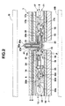
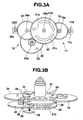
- This wristwatch comprises a watch module 1 of FIGS. 1 and 2 , which in turn comprises a seconds hand 2, a center hand 3 and an hour hand 4 which sweep around a dial 5 to indicate time and is encased within a case TK with glass G on top of the case and with a case back UB.
- the watch module 1 has an upper housing 6 and a lower housing 7 between which a watch movement 8 is provided.
- the dial 5 is provided on top of the upper housing 6 through a solar panel 9.
- a circuit board 10 is provided within the lower housing 7.
- the watch movement 8 comprises a first driving system 11 which drives the seconds hand 2 and a second driving system 12 which drives the center and hour hands 3 and 4, and a detection unit 13 that detects the rotational positions of the seconds, center and hour hands 2, 3 and 4.
- the first and second driving systems 11 and 12 are attached to a main plate 14, a train wheel bridge 15 and a center wheel bridge 16 between the upper and lower housings 6 and 7.
- the first driving system 11 comprises a first stepping motor 17, a fifth wheel 18 rotated by the first stepping motor 17, a fourth or seconds (hand) wheel 20 which is rotated by the fifth wheel 18.
- the seconds hand 2 is attached to a seconds hand shaft 20a ( FIG. 4 ).
- the first stepping motor 17 comprises a coil block 17a, a stator 17b and a rotor 17c. When a required current flows through the coil block 17a, a magnetic field will be produced, thereby rotating the rotor 17c 180 degrees at a time.
- the fifth wheel 18 rotates, meshing with a pinion 17d of the rotor 17c of the first stepping motor 17.
- the seconds wheel 20 rotates, meshing with a pinion 18a of the fifth wheel 18.
- a seconds hand shaft 20a extends upward through aligned apertures 5a in the seconds wheel 20, upper housing 6, solar panel 9 and dial 5.
- the seconds hand 2 is attached to a top of the seconds hand shaft 20a.
- the seconds wheel 20 has three different light-passing apertures 21a, 21b and 21c (For brevity of explanation, any of these apertures 21a, 21b and 21c can be described merely as 20).
- the second driving system 12 comprises a second stepping motor 22, an intermediate wheel 23 which is rotated by the second stepping motor 22, a third wheel 24 which is rotated by the intermediated wheel 23, a second or center (hand) wheel 25 rotated by the third wheel 24, a minute wheel 26 which is rotated by the center wheel 25, and an hour (hand) wheel 27 which is rotated by the minute wheel 26.
- the center hand 3 is attached to a shaft 25a of the center wheel 25 and the hour hand 4 to a shaft 27a of the hour wheel 27.
- the second stepping motor 22 comprises a coil block 22a, a stator 22b and a rotor 22c.
- a magnetic field will be produced, thereby rotating the rotor 22c 180 degrees at a time.
- the intermediate wheel 23 rotates, meshing with a pinion 22d of the second stepping motor rotor 22c.
- the intermediate wheel 23 has a circular light-passing aperture 30.
- the third wheel 24 rotates, meshing with a pinion 23a of the intermediate wheel 23 while the center wheel 25 rotates, meshing with a pinion 24a of the third wheel 24.
- the center wheel 25 has at its center an upright hollow cylindrical shaft 25a through which a shaft 20a of the seconds wheel 20 extends rotatably.
- the center hand shaft 25a extends upward through common apertures 5a provided in the upper housing 6, solar panel 9 and dial 5.
- the center hand 3 is attached to the center hand shaft 25a such that the center wheel 25 is disposed on the same axis as the seconds wheel 20 above the same.
- the center wheel 25 has a light-passing aperture 28.
- the minute wheel 26 rotates, meshing with a pinion 25a of the center wheel 25.
- the hour wheel 27 rotates, meshing with a pinion 26a of the minute wheel 26.
- the hour wheel 27 has at its center an upward protruding hollow cylindrical shaft 27a through which the shaft 25a of the center wheel 25 in turn extends rotatably.
- the hour hand shaft 27a extends upward through the apertures 5a provided in the upper housing 6, solar panel 9 and dial 5.
- the hour hand 4 is attached to top of the hour hand shaft 27a such that the hour wheel 27 is disposed on the same axis as the center wheel 25.
- the hour wheel 27 has a plurality of circular light-passing apertures 29 provided at predetermined intervals along the periphery thereof.
- FIG. 6 shows details of components of each of the first and second driving systems 11 and 12, the drive conditions of the components, etc.
- the rotor pinion 17d of the first driving system 17 rotates 180 degrees or one step per pulse.
- the fifth wheel 18 rotates 36 degrees per pulse (or per step of the rotor 17c rotation).
- the seconds wheel 20 rotates 6 degree per pulse (or per step of the rotor 17c rotation) and hence makes one rotation with 60 pulses (or in 60 steps of the rotor 17c rotation).
- the pinion 22d of the rotor 22 of the second driving system 12 rotates 180 degrees or one step per pulse.
- the intermediate wheel 23 rotates 30 degrees per pulse (or per step of the rotor 22c rotation), thereby making one rotation with 12 pulses (in 12 steps of the rotor 22c rotation).
- the third wheel 24 rotates 4 degrees per pulse (or per step of the rotor 22c rotation).
- the center wheel 25 rotates one degree per pulse (or per step of the rotor 22c rotation), and makes one rotation with 360 pulses (in 360 steps of the rotor 22c rotation).
- the minute wheel 26 rotates 1/3 degrees per pulse (per step of the rotor 22c rotation).
- the hour wheel 27 rotates 1/12 degrees per pulse (per step of the rotor 22c rotation) and hence makes one rotation with 4320 pulses (in 4320 steps of the rotor 22c rotation).
- the detection unit 13 comprises a light emission element 31, which includes a light emitting diode, and a photodetection element 32, which includes a phototransistor.
- the light emission element 31 and the photodetection element 32 are attached to the upper housing 6 and the circuit board 10, respectively.
- the arrangement is such that when one of the light-passing apertures 21a, 21b and 21c in the seconds wheel 20; the aperture 28 in the center 25; a relevant one of the apertures 29 in the hour wheel 27; and the aperture 30 in the intermediate wheel 23, respectively, align wholly or partially with an optical path or detection position P, which is set at an 0-o'clock 00-minute 00-secnd position in this embodiment, between the light emission and detection elements 31 and 32, the photodetection element 32 detects light from the light emission element 31 through those apertures, thereby detecting the respective rotational positions of the seconds, center and hour wheels 20, 25 and 27.
- the position of the optical path or detection position P is not limited to the specified example, but may be another position such as, for example, an 11-hour 55-minute position.
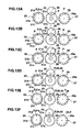
- the aperture 21a is provided as a circular one at a reference or 00-second position in the seconds wheel 20
- the apertures 21b and 21c are provided as arcuate ones on the opposite sides of the circular aperture 21a along the periphery of the seconds wheel 20 so as to be spaced by first and second light blocking areas 21d and 21e of different lengths, respectively, from the circular aperture 21a.
- a third light blocking area 21f formed between the arcuate apertures 21b and 21c is on the same diameter of the seconds wheel 20 as the circular aperture 21a.
- the seconds wheel 20 has a diameter of approximately 3 to 4 mm.
- Its circular aperture 21a has a diameter of approximately 0.4 to 0.5 mm or approximately 12 degrees indicative of an angle of the circular aperture 21a, as viewed from the center of the seconds wheel 20.
- the first arcuate aperture 21b extends between an approximately 48° or 8-second position and an approximately 168° or 28-second position in a counterclockwise direction from the circular aperture 21a on the same circumference of a circle as the circular aperture 21a. As shown in FIG.
- the second arcuate aperture 21c extends between an approximately 192° or 32-second position and an approximately 300° or 50-second position in the counterclockwise direction from the center of the aperture 21a on the same circumference of a circle as the circular aperture 21a.
- the first light blocking area 21d present in the counterclockwise direction from the reference or 0° position which is the center of the circular aperture 21a extends through an angular extent which is approximately three times 12 degrees indicative of the angle of the circular aperture 21a, as viewed from the center of the seconds wheel 20, or a net angular extent of approximately 36 degrees between the reference or 0° position which is the center of the circular aperture 21a and an approximately 48° or 8-second position as viewed in the counterclockwise direction.
- the second light blocking area 21e is longer by an angular extent corresponding to approximately the angle of the circular aperture 21a as viewed from the center of the seconds wheel 20 than the first light blocking area 21d. That is, the second light blocking area 21e extends through an angular extent of approximately 4 times the angle of the circular aperture 21a as viewed from the center of the seconds wheel 20, or through a net angular extent of approximately 48 degrees from the center of the circular aperture 21a (or the reference or 0-degree position) to an approximately 60 degree or 50-second position in the clockwise direction. As shown in FIG.
- the third light blocking area 21f is provided between the arcuate aperture 21b and 21c and has an angular extent of substantially the angle of the circular aperture 21a, as viewed from the center of the seconds wheel 20.
- the third light blocking area 21f is also on the same diameter of the seconds wheel 20 as the aperture 21a.
- the first light blocking area 21d is the same diameter of the seconds wheel 20 as part of the arcuate aperture 21c.
- the second light blocking area 21e is on the same diameter of the seconds wheel 20 as part of the arcuate aperture 21b.
- the third blocking area 21f is on the same diameter of the seconds wheel 20 as the circular aperture 21a.
- the detection unit 13 While the seconds wheel 20 rotates around a center axis thereof 2 steps, 12 degrees or 2 seconds at a time until it rotates 60 steps, 360 degrees or 60 seconds in total, the detection unit 13 detects light or apertures at intervals of 2 seconds, thereby producing a detected pattern shown in FIG. 8 . More particularly, when the seconds wheel 20 is at the position of 0 seconds or degrees, the detection unit 13 detects the circular aperture 21a. When the seconds wheel 20 rotates from a 2-second position or 12° position to a 6-second position or 36° position, the first light blocking area 21d blocks the detection position P or light path in the detection unit 13, and hence three non-detection events where the detection unit 13 cannot detect light occur successively.
- the detection unit 13 detects light or the arcuate aperture 21b continuously.
- the third light blocking area 21f blocks the detection position P, and hence the detection unit 13 cannot detect apertures.
- the detection unit 13 detects light or the arcuate aperture 21b continuously.
- the light blocking area 21e blocks the detection position P, and hence four non-detection events occur successively to the detection unit 13.
- the aperture 28 in the center wheel 25 is a circular one provided at a reference or 00-minute or 0° position in the center wheel 25.
- the aperture 28 has substantially the same size as the circular one 21a in the seconds wheel 20 and is provided on the same circumference of a circle as the circular aperture 21a in the seconds wheel 20.
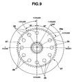
- the hour wheel 27 has the 11 circular light-passing apertures 29 arranged at angular intervals of 30° along the periphery thereof, starting at a reference, 00-o'clock or 0° position therein.
- a light blocking area 29a is provided in the hour wheel 27 between the aperture at the reference position and the eleventh aperture (i, e. at the one o'clock position in FIG. 9 ).
- the apertures 29 in the hour wheel 27 are provided at respective angular positions of 0, 30, 60, 90, 120, 150, 180, 210, 240, 270 and 300° in the counterclockwise direction or at positions of 0, 1, 2, 3, 4, 5, 6, 7, 8, 9 and 10 o'clock with a 00-o'clock or 0° position as a reference position in the hour wheel 27 in the clockwise direction (in FIG. 9 , in the counterclockwise direction).
- the fourth light blocking area 29a is provided at an 11 o'clock position (or a one o'clock position in FIG. 9 ).
- These circular apertures 29 in the hour wheel 27 have substantially the same size as the aperture 21a in the seconds wheel 20.
- the aperture 30 in the intermediate wheel 23 can align with the aperture 28 in the center wheel 25 and has substantially the same size as the apertures 21a and 28 in the seconds and center wheels 20 and 25.
- the aperture 30 is provided at such a position in the intermediate wheel 23 that when the aperture 28 in the center wheel 25 aligns with the detection position P, the aperture 30 aligns with the aperture 28 in the center wheel 25.
- the detection unit 13 tries to detect light at each of the 0, 1, 2, ... and 11 o'clock.
- the intermediate, center and hour wheels 23, 25 and 27 of the second driving system 12 rotate 30°, 1° and (1/12)°, respectively, in one step or a half rotation of the rotor 22c.
- the arrangement is such that at each of the time o'clock excluding the 11 o'clock, the apertures 28 and 30 in the center and intermediate wheels 25 and 23 and a relevant one of the apertures 29 in the hour wheel 27 align all at the detection position P.
- the seconds wheel 20 of the first driving system 11 rotates 6 degrees (or a half rotation of the rotor 17c) per step.
- Each time the seconds wheel 20 rotates 60 steps or seconds its aperture 21a aligns with the detection position P.
- the aperture 21a aligns with the apertures 28, 30 and a relevant one of the apertures 29.
- the detection units 13 detects the driving positions of the seconds, center and hour hands 2, 3 and 4 as follows: when the seconds, center and hour hands 2, 3 and 4 point to the same direction at the 12 o'clock position (the top position in FIG. 5 ), a relevant one of the apertures 21a, 21b and 21c in the seconds wheel 20, the aperture 28 in the center wheel 25, a relevant one of the apertures 29 in the hour wheel 29 and an intermediate wheel 23 align wholly or partially with the detection position P in FIG. 5 and a light beam from the light emission element 31 should be detected through these apertures by the photodetection element 32.
- the detection unit 13 tries to detect light at every two steps (or seconds) of the seconds wheel 20 rotation.
- the detection unit 13 tries to detect light at each step of rotation of each of these wheels.
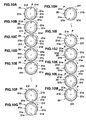
- FIGS. 10A to 10M description will be made of a basic seconds hand position detecting method for detecting a reference or 00-second position in the seconds wheel 20.
- the minute, hour and intermediate wheels 25, 27 and 23 of the second driving system 12 should be neglected.
- FIGS. 10A to 10M each show a relationship between the detection position P of the detection unit 13 and a rotational angular position of the seconds wheel 20 when the same rotates two steps (or a rotational angle of 12 degrees) at a time.
- the basic method is achieved by detecting the reference or 00-second position in the seconds wheel 20 of FIG. 10A where the aperture 21a in the seconds wheel 20 aligns with the detection position P. In this state, the detection unit 13 can detect light.
- the aperture 21a in the seconds wheel 20 moves clockwise away from the detection position P and the first light blocking area 21d covers the detection position P, as shown in FIG. 10B .
- the detection unit 13 cannot detect light, as shown at a 2-second position in FIG. 8 .
- the third light blocking area 21d blocks the detection position P.
- the detection unit 13 cannot detect light and three non-detection events occur successively, as shown at 3 to 6 second positions in FIG. 8 .
- the detection unit 13 can detect light.
- the detection unit 13 can detect light continuously, as shown at 10 to 28 second positions in FIG. 8 .
- the detection unit 13 detects light continuously.
- the detection unit 13 can not detect light, as shown at a 52-second position in FIG. 8 .
- the detection unit 13 cannot detect light.
- four non-detection events occur successively.
- the aperture 21a in the seconds wheel 20 aligns with the detection position P, as shown in FIG. 10A .
- the detection unit 13 detects light.
- the detection unit 13 can detect light. In the states of FIGS. 10B to 10D , the detection unit 13 can not detect light successively three times. In the states of FIGS. 10E and 10F , the detection unit 13 can detect light successively. In the state of FIG. 10G , the detection unit 13 cannot detect light. In the states of FIGS. 10H and 10I , the detection unit 13 can detect light successively. In the states of FIGS. 10J to 10M , the detection unit 13 can not detect light successively four times.
- the detection unit 13 cannot detect light in both the states of FIGS. 10B to 10D and FIGS. 10J to 10M .
- the detection unit 13 tries to detect light once every two steps, in the former state three non-detection events occur successively whereas in the latter case four non-detection events occur successively. It will be known that the former and latter cases are different in the number of successive non-detection events. By counting this number of successive non-detections, the reference position in the seconds wheel 20 can be located as follows.
- the detection unit 13 tries to detect light.
- the aperture 21a aligns with the detection position P.
- the reference or 00-second position in the seconds wheel 20 has aligned with the detection position P.
- the detection unit 13 can detect light.
- the conditions of four successive non-detection events are not met and it will be known that the reference position in the seconds wheel 20 has not aligned with the detection position P. This is the basic position detecting process for detecting the reference position in the seconds wheel 20.
- FIGS. 11A to 11P description will be made of a basic hour and minute position detecting process for detecting the respective reference positions in the hour and minute wheels 27 and 25.
- the seconds wheel 20 in the first driving system is ignored.
- FIGS. 11A to 11M illustrate that the center wheel 25 has rotated one step or degree at a time, thereby causing the intermediate wheel 23 to make one rotation.
- FIGS. 11M to 11N illustrate that the center wheel 25 has rotated 360 steps or degrees, thereby rotating the hour wheel 27 by 30 degrees.
- FIG. 11N to 11O show that the hour wheel 27 has rotated 9 hours from the state of FIG. 11N (or 10 hours in all).
- FIGS. 11O to 11P show that the hour wheel 27 has rotated one more hour (or 11 hours in all).
- Both the reference or 0-o'clock and 00-minute positions in the center and hour wheels 25 and 27 can be detected best in the state of FIG. 11A .
- the reference position of the aperture 28 in the center wheel 25 is a 00-minute position and the reference position of the relevant one of the apertures 29 in the hour wheel 27 is a 0-o'clock position.
- it is required to detect the reference positions in the center and hour wheels 25 and 27 which align with the detection position P and the aperture 30 in the intermediate wheel 23.
- the intermediate wheel 23 rotates 30 degrees, its aperture 30 moves counterclockwise away from the detection position P, and then the intermediate wheel 23 covers the detection position P, as shown in FIG. 11B .
- the center wheel 25 rotates clockwise one degree, and its aperture 28 moves slightly, but not completely, away from the detection position P in the detection unit 13 and hence the detection unit 13 can still detect light.
- the intermediate wheel 23 rotates 180 degrees clockwise, its aperture 30 rotates counterclockwise 180 degrees away from the detection position P, and thus the intermediate wheel 23 continues to cover the detection position P, as shown in FIG. 11G .
- the center wheel 25 rotates 6 degrees clockwise and its aperture 28 moves a half of its size away from the detection position P, but the detection unit 13 still detects light ( FIG. 25 ).
- the intermediate wheel 23 rotates 360 degrees and its aperture 30 aligns with the detection position P, as shown in FIG. 11M .
- the aperture 28 in the center wheel 25 is substantially completely offset from and aligns hardly with the detection position P.
- the center wheel 25 covers the detection position P, which can not detect light.
- the hour wheel 27 rotates only one degree, the circular aperture 29 at the reference position in the hour wheel 27 is only slightly offset from the detection position P and the detection unit 13 can still detect light.
- the center wheel 25 rotates 360 steps or makes one rotation clockwise from the state of FIG. 11A
- the apertures 28 and 30 in the minute and intermediate wheel 25 and 23 align with the detection position P, as shown in FIG. 11N .
- the hour wheel 27 has rotated 30 degrees clockwise from the state of FIG. 11A ; the aperture 29 at the reference position in the hour wheel 27 has moved away from the detection position P; a second left aperture from the aperture 29 at the reference position aligns with the detection position P; and hence the detection unit 13 can detect light.
- the center wheel 25 rotates 9 hours (or 10 hours in all) from this state
- the apertures 28 and 30 in the minute and intermediate wheels 25 and 23 align with the detection position P, as shown in FIG. 11O .
- the hour wheel 27 has rotated 300 degrees.
- an eleventh aperture present counterclockwise from the aperture 29 at the reference position aligns with the position P and the detection unit 13 can detect light.
- the apertures 28 and 30 in the minute and intermediate wheels 25 and 23 align with the detection position P, as shown in FIG. 11P .
- the hour wheel 27 has rotated 330 degrees; the eleventh aperture from the aperture 29 at the reference position has moved away from the detection position P; and the light blocking area 29a in the hour wheel 27 covers the detection position P.
- the detection unit 13 cannot detect light. That is, it can be said that the hour wheel 27 is at an 11-o'clock 00minute position.
- the apertures 28 and 30 in the center and intermediate wheels 25 and 23 align with the detection position P, as shown in FIG. 11A .
- the hour wheel 27 has rotated 360 degrees; the light blocking area 29a of the hour wheel 27 has moved away from the detection position P; and the aperture 29 at the 0-o'clock position in the hour wheel 27 aligns with the detection position P.
- the hour wheel 27 returns to the state of FIG. 11A .
- the rotational amount per step of the center wheel 25 is very small or one degree, it is not enough for the rotational amount per step of the center wheel 25 to cause the aperture 28 to move completely away from the detection position P, and the reference position in the center wheel 25 can not be detected accurately.
- the intermediate wheel 23 rotates 30 degrees per one step. Thus, even when the rotational amount per step of the center wheel 25 is small, the rotational amount of the intermediate wheel 23 is large enough to cover the detection position P.
- the center wheel 25 rotates 12 degrees.
- the aperture 28 in the center wheel 25 moves completely away from the detection position P and hence the center wheel 25 covers the detection position P.
- the detection unit 13 cannot detect light.
- the detection unit 13 can detect light in spite of the rotational position of the hour wheel 27 excluding the 11 o'clock position.
- the hour wheel 27 rotates 30 degrees at a time.
- the rotational position of the hour wheel 27 can be detected if the detection unit 13 tries to detect light only when the center wheel 25 makes one rotation.
- the detection unit 13 cannot detect light because the light blocking area 29a in the hour wheel 27 has covered the detection position P, as shown in FIG. 11P .
- the reference position in the hour wheel 27 at this time is specified as an "11-o'clock 00-minute position".
- the aperture 29 at the reference or 0-o'clock position in the hour wheel 27 aligns with the detection position P and the detection unit 13 can detect light. That aperture 29 in the hour wheel 27 at this time is at the reference or 0-o'clock 00-minute position.
- the detection unit 13 tries to detect light. Then, when the position in the hour wheel 25 ( FIG. 11A ) where the detection unit 13 can detect light is found by rotating the center wheel 25 further 360 degrees from the position where the detection unit 13 can not detect light ( FIG. 11P ), it can be specified as the reference or 0-o'clock 00 minute position in the hour wheel 27.
- This process comprises a seconds hand position detecting operation to be performed when any of the apertures 21a, 21b and 21c in the seconds wheel 20 is offset from the detection position P, an hour/minute hand position detecting process to be performed when the aperture 28 in the center wheel 25 or a relevant one of the apertures 29 in the hour wheel 27 is offset from the detection position P, and a combination of the seconds hand position detecting operation and hour/minute hand position detecting process to be performed when one of the apertures 21a, 21b and 21c in the seconds wheel 20, the aperture 28 in the center wheel 25 and a relevant one of the apertures 29 in the hour wheel 27 are all offset from the detection position P.
- the detection unit 13 can not detect light, and this state is counted as one non-detection event.
- the number of these non-detection events is sequentially counted up and then when the detection unit 13 detects light, the count obtained so far is cleared.
- the seconds wheel 20 is rotated further two steps, thereby causing the detection unit 13 to try to detect light.
- FIG. 12B if at this time the detection unit 13 can not detect light, it is determined that another non-detection event has occurred and hence is counted. Then, the seconds wheel 20 is rotated further two steps from this state, thereby causing the detection unit 13 to try to detect light. If the detection unit 13 detects light at this time, as shown in FIG. 12C , non-detection events do not occur successively, and the counted number of non-detection events obtained so far is cleared.
- the detection unit 12 tries to detect light each time the seconds wheel 20 is rotated two steps.
- FIG. 12D at this time, when a state where the detection unit 13 cannot detect light occurs after the detection unit 13 has successfully detected light successively so far, this state is counted again as one non-detection event. Then, light detection is tried each time the seconds wheel 20 is rotated two steps. At this time, four non-detection events occur successively in which the detection unit 13 cannot detect light, as shown in FIG. 12E .
- the detection unit 13 can detect light in next two steps, it can be said that the aperture 21a in the seconds wheel 20 has aligned with the detection position P. Thus, it will be known that the position of the aperture 21a is its reference position, as shown in FIG. 12F .
- the basic seconds wheel position detecting method involves the fact that if the detection unit 13 tries to detect light, encounters four non-detection events successively and detects light in next two steps, the position of the aperture in the seconds wheel 20 at this time is a reference position in the seconds wheel 20. In view of this method, in the state of FIG. 13B , four non-detection events have occurred successively. Thus, if the detection unit 13 detects light in next two steps, it can be said that the reference position in the seconds wheel 20 at this time has aligned wit the detection position P. However, as shown in FIG. 13C , the apertures 28 and 29 in the center and hour wheels 25 and 27 are offset from the detection position P even when the seconds wheel 20 is rotated two steps. Thus, the detection unit 13 cannot detect light.
- the detection unit 13 cannot detect light successively five times once each time the seconds wheel 20 rotates two steps, it is known that either the aperture 28 in the center wheels 25 or any of the apertures 29 in hour wheel 27 is offset from the detection position P. In this state, it is unknown whether the aperture 21 in the seconds wheel 10 aligns wholly or partially with the detection position P.
- the seconds wheel 20 is rotated one step at a time, thereby causing the detection unit 13 to detect light. Therefore, when the state of the center and hour wheels 25 and 27 changes from that of FIG. 13C to that of FIG. 13D , the apertures 28 and 30 in the center and intermediate wheels 25 and 23 align with the detection position P and a relevant one of the apertures 29 in the hour wheel 27 also aligns with the detection position P. Thus, the detection unit 13 can detect light.
- the detection unit 13 can detect light.
- a basic seconds position detecting process for detecting the reference position in the seconds wheel 20 is tried by moving the seconds wheel 20 to the position of FIG. 13E where the reference or 00-second position in the seconds wheel 20 aligns with the detection position P.
- the respective reference positions in the seconds and center wheels 20 and 25 are at a 00-minute and 00-second position, which occurs at 0 o'clock, 00 minutes, 00 seconds.
- the respective apertures 29 in the hour wheel 27 align sequentially with the detection position P.
- the detection unit 13 can detect light.
- the center wheel 25 is further rotated 360 degrees from the state or 11 o'clock position where the detection unit 13 cannot detect light
- the reference or 0-o'clock position in the hour wheel 27 aligns with the detection position P.
- the respective reference positions in all the seconds, center and hour wheels 20, 25 and 27 are at the 0-o'clock 00-minute 00-second position which aligns with the detection position P.
- FIGS. 14A to 14F description will be made of a three-hand position detecting process for detecting the three-hand positions when any of the apertures 21, 28 and 29 in the seconds, center and hour wheels 20, 25 and 27 is offset from the detection position P.
- the rotational positions of these wheels 20, 25 and 27 are unknown.
- a basic seconds hand position detecting process for detecting the reference position of the seconds wheel 20 will be tried by rotating the seconds wheel 20 two steps at a time from the state of FIG. 14A .
- FIG. 14B at this time even when the aperture 21 in the seconds wheel 20 aligns wholly or partially with the detection position P, the detection unit 13 cannot detect light if none of the apertures 28 and 29 in the center and hour wheels 25 and 27 aligns with the detection position P.
- the conditions for detecting the reference position in the seconds wheel are that the detection unit 13 tries to detect light each time the seconds wheel 20 rotates two steps at a time, encounters four successive non-detection events, and then detects light successfully in next two steps.
- the reference position in the seconds wheel 20 at this time aligns with the detection position P and is detected.
- FIG. 14C if the detection unit 13 cannot detect light even when the seconds wheel 20 rotates in the next two steps, it is determined that any of the apertures 28 and 29 in the center and hour wheels 25 and 27 is offset from the detection position P. At this time, it is also unknown whether the aperture 21 in the seconds wheel 20 has aligned with the detection position P.
- the aperture 21 necessarily aligns wholly or partially with detection position P, as shown in FIG. 14E , which is assumed so.
- the center wheel 25 is again rotated one step at a time, thereby causing the detection unit 13 to detect light.
- the aperture 28 in the center wheel 25 aligns with detection position P, thereby causing the detection unit 13 to detect light, it can be said that the reference or 00-minute position in the center wheel 25 is as shown in FIG. 14F . If appropriate operations as bring about the states of FIGS. 13E and 13F sequentially following the state of FIG. 13D are performed, all the reference positions in the seconds, center and hour wheel 20, 25 and 27 align.
- FIG. 15A shows that the apertures 21a and 28 in the seconds and center wheels 20 and 25, a relevant (for example, third) one of the apertures 29 in the hour wheel 27 and the aperture 30 in the intermediate wheel 23 align with the detection position P at a particular, for example, 2 o'clock in the normal hand driving operation. From this state, the seconds wheel 20 rotates one step (or 6 degrees) at a time. Thus, the aperture 21a in the seconds wheel 20 does not completely move away from the detection position P and the detection unit 13 can detect light.
- the aperture 21a in the seconds wheel 20 moves completely away from the detection position P and the first light blocking area 21d covers the detection position P, as shown in FIG. 15B . Even if the detection unit 13 tries to detect light at this time, the detection unit 13 cannot detect light. Thus, this non-detection event is counted.
- the seconds wheel 20 rotates one step at a time and the detection unit 13 tries to detect light each time.
- the first light blocking area 21d of the seconds wheel 20 continuously covers the detection unit 13, as shown at 4- and 6-second positions in FIGS. 15C and 15D , respectively.
- FIGS. 15B to 15D three non-detection events occurs successively.
- the arcuate aperture 21b in the seconds wheel 20 aligns with the detection position P, thereby causing the detection unit 13 to detect light, and the aperture 21a at the reference position in the seconds wheel 20 is at an 8-second position.
- the detection unit 13 tries to detect light.
- the seconds hand 2 is at the 8-second position. This indicates that the seconds hand 2 sweeps around exactly.
- the arcuate aperture 21b in the seconds wheel 20 aligns with the detection position P and the detection unit 13 can detect light, as shown in FIG. 15F .
- the center wheel 25 rotates one step or degree and the intermediate wheel 23 rotates one step or 30 degrees.
- the aperture 28 in the center wheel 25 is not completely offset from the detection position P
- the aperture 30 in the intermediate wheel 23 is completely offset from the detection position P, thereby causing the intermediate wheel 23 to cover the detection unit 13.
- hand setting in the usual hand driving operation is required to be performed in 10 seconds from the related time o'clock.
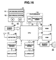
- the circuit configuration of this wristwatch comprises a CPU 35 which controls the whole circuit, a ROM 36 which has stored predetermined programs, a RAM 37 which stores data to be processed, an oscillator 38 which generates a pulse signal to operate the CPU 35, a frequency divider 39 which converts the pulse signal generated by the oscillator 38 to an appropriate frequency to operate the CPU 35, a watch movement 8 which causes the seconds, center and hour hands 2, 3 and 4 to sweep around the dial, and the detection unit 13 which comprises a light emission element 31 and a photodetection element 32 which detects light from the light emission element 31. While in this specification, various controlling and processing operations which are performed by the CPU 5 are indicated, the CPU 35 is not especially described conspicuously.
- the circuit further comprises a power supply 40 which includes a solar panel 9, and a battery to supply power, an antenna 41 which receives a standard radio wave, a wave detector 42 which detects the received standard radio wave, an illuminator 43 which illuminates time indications, a driver 44 which drives the illuminator 43, a speaker 45 which emanates sound and a buzzer circuit 46 which drives the speaker 45.
- a power supply 40 which includes a solar panel 9, and a battery to supply power
- an antenna 41 which receives a standard radio wave
- a wave detector 42 which detects the received standard radio wave
- an illuminator 43 which illuminates time indications
- a driver 44 which drives the illuminator 43
- a speaker 45 which emanates sound
- a buzzer circuit 46 which drives the speaker 45.
- This process includes detecting the reference or 00-second position in the seconds wheel 20 where the aperture 21a in the seconds wheel 20 aligns with the detection position P, as shown in FIG. 10A .
- the apertures 28 and 30 in the center and intermediate wheels 25 and 23 and a relevant one of the apertures 29 in the hour wheel 27 have aligned with the detection position P and that these wheels are at a stop.
- step S1 the counted number of non-detection events which the detection unit 13 has encountered so far is cleared, thereby resetting a non-detection flag bit to 0 (step S1).
- step S2 the motors 11 and 12 of the watch movement 8 are driven, thereby rotating the seconds wheel 20 two steps or 12 degrees (step S2).
- step S3 the light emission element 31 of the detection unit 13 is caused to emit light (step S3) and then it is determined whether the photodetection element 32 has detected light from the light emission element 31 or whether the detection unit 13 has detected light.
- the photodetection element 32 detects no light from the light emission element 31. This non-detection event is counted, thereby setting the non-detection flag bit to "1" (step S5). Then, it is determined whether four non-detection events have occurred successively to the detection unit 13 (step S6).
- the detection unit 13 since in the state of FIG. 10G the light blocking area 21f of the seconds wheel 20 covers the detection position P, the detection unit 13 does not detect light. Then, when the seconds wheel 20 rotates two steps, the arcuate aperture 21c in the seconds wheel 20 aligns partially with the detection position P, and the detection unit 13 detects light. Also at this time, the control returns to the step S2 to repeat the steps S1 to S4.
- the control passes to an hour and center hand detecting process which will be described next.
- the seconds wheel 20 is rotated two steps (step S7), the light emission element 31 is caused to emit light (step S8), and then it is determined whether the photodetection unit 32 has received light from the light emission element 31 (step S9). If the photodetection unit 32 has received light from the light emission element 31, it can be said that the aperture 21a in the seconds wheel 20 has aligned with the detection position P. Thus, it is determined that the reference or 00-second position in the seconds wheel 20 has been detected. Then, a hand position correction process is performed, thereby returning the seconds, center and hour hands 2, 3, and 4 to the current time (step S10), and thus the watch is returned to its usual hand driving operation, thereby terminating this process.
- step S9 it is assumed that the respective apertures 28 and 30 in the center and intermediate wheel 25 and 23 and a relevant one of the apertures 29 in the hour wheel 27 have aligned with the detection position P and are at a stop there.
- the detection unit 13 necessarily detects light.
- the detection unit 13 will detect no light.
- FIG. 18 description will be made of a basic center hand position detecting process for detecting a reference position of the center hand 3 of the hand type wristwatch, which involves detecting a reference or 00-minute position in the center wheel 25 which has aligned with the detection position P along with the apertures 28 and 30 in the center and intermediate wheels 25 and 23, as shown in FIG. 11A .
- a relevant one of the apertures 29 in the hour wheel 27 has also aligned with the detection position P.
- step S12 the center wheel 25 is rotated clockwise one step or degree (step S12), the light emission element 31 is caused to emit light (step S13), and then it is determined whether the photodetection element 32 has received light from the light emission element 31 (step S14). If not, the control repeats the steps S12 to S14 until the seconds wheel 25 is rotated 360 degrees or one hour (step S15).
- the detection unit 13 detects light even when the center wheel 25 rotates 360 degrees (or one hour), it is determined that the aperture 21 in the seconds wheel 20 is offset from the detection position P.
- the seconds wheel 20 is rotated 30 steps (or 180 degrees), thereby causing the aperture 21 in the seconds wheel 20 to align wholly or partially with the detection position P (step S16).
- the steps S12 to S15 are repeated until the seconds wheel 25 is rotated 360 degrees again from this state.
- the detection unit 13 detects light in step S14, it is determined that the reference position in the center wheel 25 has aligned with the detection position P. At this time, it is necessary to confirm whether this determination is correct.
- the center and intermediate wheels 25 and 23 are rotated such that when the intermediate wheel 23 makes one rotation to return to the detection position P and the center wheel 25 is rotated 12 steps to move away 12 degrees from the detection position P, the photodetection element 32 can detect light through the apertures 28 and 30 in the center and intermediate wheels 25 and 23 from the light emission element 31 if there are errors in the manufacture or assembly of the center and intermediate wheels 25 and 23.
- the center wheel 25 is returned or reversely rotated 12 steps or more from the rotational position thereof where the detection unit 13 detected light in step S14, or 12 degrees or more enough for the aperture 28 in the center wheel 25 to move substantially completely away from the detection position P (step S17).
- the aperture 28 in the center wheel 25 should be completely offset from the detection position P.
- the center wheel 25 is again rotated clockwise one step at a time from the position to which the center wheel 25 was returned (step S18), the light emission element 31 is caused to emit light (step S19), and then it is determined whether the photodetection element 32 has detected light from the light emission element 31 or whether the detection unit 13 has detected light (step S20).
- step S20 Unless the detection unit 13 detects light in step S20, the steps S18 to S20 are repeated until the center wheel 25 is rotated 12 steps or more (step S21). At this time, the detection unit 13 should detect light necessarily. Otherwise, an error display is performed (step S22). If the detection unit 13 detects light in step S20, it is determined that the position of the aperture 28 in the center wheel 25 where the detection unit 13 detected light this time is the reference or 00-minute position in the center wheel 25 (step S23). Then, this process is terminated.
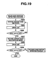
- FIG. 19 description will be made of a basic hour hand position detecting process for detecting a reference position of the hour hand 4 of the wristwatch.
- This process involves detecting a reference or 0-o'clock position in the hour wheel 27 as shown in FIG. 11A where the aperture 29 at the reference position in the hour wheel 27 and the apertures 28 and 30 in the center and intermediate wheels 25 and 23 align with the detection position P.
- the reference position in the center wheel 25 has aligned wholly or partially with the detection position P and that the aperture 21 in the seconds wheel 20 has aligned with the detection point P.
- the center wheel 25, where its aperture 28 has aligned with the detection position P is rotated 360 degrees, thereby rotating the hour wheel 27 by 30 degrees (step S24).
- the light emission element 31 of the detection unit 13 is then caused to emit light (step S25), and then it is determined whether the photodetection element 32 has received light from the light emission element 31. That is, it is determined whether one of the apertures 29 in the hour wheel 27 has aligned with the detection position P and the detection unit 13 has detected light (step S26).
- the hour wheel 27 has 11 circular apertures 29 therein provided at angular intervals of 30 degrees along the circumference thereof with the fourth light blocking area 29a at the 11 o'clock position.
- the respective apertures 29 in the hour wheel 27 sequentially align with the detection position P and the detection unit 13 detects light, excluding at the fourth light blocking area 29a at the 11 o'clock position, as shown in FIGS. 11N and 11O .
- step S26 when the detection unit 13 detects light in step S26, the control returns to step S24 to repeat the steps S24 to S26 until the fourth light blocking area 29a of the hour wheel 27 covers the detection position P, thereby disabling the detection unit 13 from detecting light after the respective apertures 29 in the hour wheel 27 sequentially align with the detection position P.
- step S27 if the detection unit 13 detects no light due to the fourth light blocking area 29a of the hour wheel 27 covering the detection position P, it is determined that the hour wheel 27 is at its 11 o'clock position, and the center wheel 25 is rotated further 360 degrees, thereby rotating the hour wheel 27 further 30 degrees (step S27). Then, the light emission element 31 is caused to emit light (step S28), and then it is determined whether the photodetection element 32 has detected light from the light emission element 31 and hence whether the detection unit 13 has detected light (step S29).
- step S29 a relevant one of the apertures 29 at the 0-o'clock position in the hour wheel 27 aligns necessarily with the detection position P and the detection unit 13 detects light.
- the reference or 0-o'clock position in the hour wheel 27 has aligned with the detection position P, and then this process is terminated.
- the aperture 21 in the seconds wheel 20 has aligned wholly or partially with the detection position P.
- the detection unit 13 should necessarily detect light. Otherwise, it is determined that the aperture 21 in the seconds wheel 20 has not aligned with the detection position P. Then, the control returns to the seconds hand position detecting process.
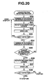
- FIGS. 20 to 23 description will be made of a basic 3-hand position detecting process for detecting the reference positions of the seconds, center and hour hands 2, 3 and 4 of the wristwatch.
- This process involves a combination of the seconds hand position detecting process and the hour and center hand position detecting process.
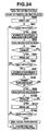
- FIG. 20 shows steps S30 to S38 of the seconds hand position detecting subprocess.
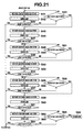
- FIG. 21 shows steps S41 to S66 of the center hand position detecting subprocess.
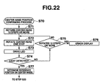
- FIG. 22 show steps S70 to S77 of the center hand position detecting subprocess.
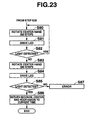
- FIG. 23 show steps S80 to S87 of the hour hand position detecting subprocess.
- the seconds hand position detecting process of FIG. 20 is performed because none of the positions of the seconds, center and hour hands 2, 3 and 4 is known. To this end, the number of non-detection events having occurred to the detection unit 13 so far is cleared, thereby resetting the non-detection flag bit to 0 (step S30).
- the seconds wheel 20 is rotated two steps (step S31). Then, the light emission element 31 is caused to emit light (step S32). Then, it is determined whether the photodetection element 32 has detected light from the light emission element 31 and hence whether the detection unit 13 has detected light (step S33).
- step S33 When the detection unit 13 detects light in step S33, all the apertures 21, 28 and 30 in the seconds, center and intermediate wheels 20, 25 and 23 and a relevant one of the apertures 29 in the hour wheel 27 have aligned accidentally with the detection position P. At this time, the reference 00-minute position in the center wheel 25 has aligned with the detection position P, but the rotational positions of the seconds and hour wheels 20 and 27 are unknown. Thus, first, the rotational position of the seconds wheel 20 is detected. To this end, the steps S30 to S33 are repeated until any one of the light blocking areas 21d to 21f in the seconds wheel 20 covers the detection position P, thereby disabling the detection unit 13 from detecting light.
- step S33 When one of the light blocking areas 21d to 21f in the seconds wheel 20 covers the detection position P, thereby disabling the detection unit 13 from detecting light in step S33, a non-detection event occurring to the detection unit 13 is counted by a counter (not shown) which may be included in the CPU 35 and the non-detection flag bit is set to 1 (step S34). Then, it is determined whether four non-detection events have occurred successively (step S35). Then, the steps S31 to S35 are repeated until in step S35 four non-detection events occur successively to the detection unit 13 due to the light blocking area 21e in the seconds wheel 20 covering the detection position P.
- the seconds wheel 20 is rotated two steps (step S36), and the light emission element 31 is caused to emit light (step S37). Then, it is determined whether the photodetection element 32 has detected light from the light emission element 31, and hence whether the detection unit 13 has detected light (step S38).
- step S38 If the detection unit 13 has detected light in step S38, it is determined that the reference or 00-minute position in the center wheel 25 has aligned with the detection position P, and that the aperture 28 in the center wheel 25, a relevant one of the apertures 29 in the hour wheel 27, and the aperture 21a in the seconds wheel 20 have aligned with the detection position P. Thus, it is determined that the respective reference positions in the seconds and center wheels 20 and 25 are at the 00-minute 00-second position. Then, the control passes to an hour hand position detecting process in step S80.
- step S38 When in step S38 the detection unit 13 has detected no light, five non-detection events occur successively to the detection unit 13 even when the circular aperture 21a in the seconds wheel 20 has aligned with the detection position P, as shown in FIG. 14B . Thus, it is determined that one of the apertures 28 and 30 in the center and intermediate wheels 25 and 23 and a relevant one of the apertures 29 in the hour wheel 29 is offset from the detection position P. Then, the control passes to step S41 in FIG. 21 to perform the center hand position detecting process.
- the center wheel 25 is rotated one step or degree in step S41; the light emission element 31 is caused to emit light (step S42); and then it is determined whether the photodetection element 32 has detected light from the light emission element 31, and hence whether the detection unit 13 has detected light (step S43). Otherwise, the center wheel 25 is rotated one step at a time, and then it is determined whether the seconds wheel 25 has rotated 360 degrees (step S44). Otherwise, the steps S41 to S43 are repeated until the center wheel 25 makes one rotation.
- step S43 When the detection unit 13 has detected light in step S43, it will be known that the apertures 21, 28 and 30 in the seconds, center and intermediate wheels 20, 25 and 23 and a relevant one of the apertures 29 in the hour wheel 27 have all aligned wholly or partially with the detection position P. It will also be known that before the center wheel 25 starts to be rotated in the step S41, the apertures in the center and hour wheels 25 and 27 were offset from the detection position P. Since it is assumed that the detection unit 13 has now detected light, it is determined that the reference or 00-minute position in the center wheel 25 has aligned with the detection position P. Then the control passes to step S70 to perform a center hand position confirming process to confirm whether this determination is correct.
- step S44 If the detection unit 13 detects no light even when the center wheel 25 is rotated 360 degrees in step S44, it is determined that as shown in FIG. 14D that the apertures 21 align neither wholly nor partially with the detection position P. Thus, the seconds wheel 20 is rotated 30 steps or 180 degrees (step S45), and the light emission element 31 is caused to emit light (step S46). Then, it is determined whether the photodetection element 32 has received light from the light emission element 31, and hence whether the detection unit 13 has detected light (step S47).
- the detection unit 13 When in the step S47 the detection unit 13 has detected light, it will be known that the apertures 21, 28 and 30 in the seconds, center and intermediate wheels 20, 25 and 23, and a relevant one of the apertures 29 in the hour wheel 27 have aligned wholly or partially with detection position P, and that before the seconds wheel 20 starts to be rotated in the step S45 the seconds wheel 20 was offset from the detection position P. Also in this case, since it is assumed that in the step S47 the detection unit 13 has detected light, it is determined that the reference or 00-minute position in the center wheel 25 has aligned with the detection position P and then the control passes to step the center hand position confirming process in the step S70.
- step S48 the center wheel 25 is rotated one step (step S48).
- step S49 the light emission element 31 is caused to emit light
- step S50 it is determined whether the photodetection element 32 has detected light from the light emission element 31, and hence whether the detection unit 13 has detected light
- step S50 the center wheel 25 is rotated one step at a time, and then it is determined whether the center wheel 25 has rotated 360 degrees (step S51). Otherwise, the steps S48 to S51 are repeated until the center wheel 25 makes one rotation.
- the detection unit 13 detects light in the step S50, it will be known that the apertures 21, 28 and 30 in the seconds, center and intermediate wheels 20, 25 and 23, and a relevant one of the apertures 29 in the hour wheel 27 have all aligned wholly or partially with the detection position P, and that before the center wheel 25 started to rotate in the step S50 the aperture in the center wheel 25 was offset from the detection position P. Since it is assumed that the detection unit 13 has now detected light in the step S50, it is determined that the reference or 00-minute position in the center wheel 25 has aligned with the detection position P. Then, the control passes to the step S70 for the center hand position confirming process.
- the detection unit 13 detects no light in the step S50 even when the center wheel 25 is rotated 360 degrees in the step S51, then it is determined that any of the apertures 29 in the hour wheel 27 is offset from the detection position P and that the light blocking area 29a in the hour wheel 27 covers the detection position P even when the apertures 21, 28 and 30 in the seconds, center and intermediate wheels 20, 25 and 23 align wholly or partially with the detection position P, as shown in FIG. 11P .
- the seconds wheel 20 is rotated 30 steps or 180 degrees (step S52), and the light emission element 31 is caused to emit light (step S53). Then, it is determined whether the photodetection element 32 has detected light, and hence whether the detection unit 13 has detected light (step S54).
- the apertures 21 and 28 in the seconds and center wheels 20 and 25, a relevant one of the apertures 29 in the hour wheel 27 and the aperture 30 in the intermediate wheel 23 have all aligned wholly or partially with the detection position P; that the light blocking area 29a of the hour wheel 27 does not cover the detection position P; and that before the seconds wheel 20 started to be rotated in the step S52, the aperture 21 in the seconds wheel 20 was offset from the detection position P. Also, since it is assumed that the detection unit 13 has detected light, it is determined that at this time the reference or 00-minute position in the center wheel 25 has aligned with the detection position P. Then, the control passes to the step S70 for the center hand position confirming process.
- step S54 When the detection unit 13 does not detect light in the step S54, it is determined that the fourth light blocking are 29a of the hour wheel 27 blocks the detection position P, as shown in FIG. 11P .
- the center wheel 25 is rotated one step (step S55), and the light emission element 31 is caused to emit light (step S56). Then, it is determined whether the photodetection element 32 has detected light from the light emission element 31, and hence whether the detection unit 13 has detected light (step S57). Otherwise, the center wheel 25 is rotated one step at a time, and it is determined whether the center wheel 25 has been rotated 360 degrees (step S58). Otherwise, then the steps S55 to S57 are repeated until the center wheel 25 makes one rotation.
- the apertures 21 and 28 in the seconds and center wheels 20 and 25, a relevant one of the apertures 29 in the hour wheel 27 and the aperture 30 in the intermediate wheel 23 align all wholly or partially with the detection position P.
- the light blocking area 29a of the hour wheel 27 does not block the detection position P and before the center wheel 25 started to be rotated in the step S55, the aperture 28 in the center wheel 25 was offset from the detection position P. Since it is now assumed that in the step S47 the detection unit 13 has detected light, it is determined that the reference or 00-minute position in the center wheel 25 has aligned with the detection position P. Then, the control passes to the step S70 for the center hand position confirming process.
- step S57 If the detection unit 13 has detected no light in the step S57 even when the center wheel 25 is rotated 360 degrees in step S58, it is conjectured that the light blocking area 29 of the hour wheel 27 blocks the detection position P and hence that the hour wheel 27 is at the 11-o'clock position.
- the seconds wheel 20 is rotated 30 steps or 180 degrees (step S59); the light emission element 31 is caused to emit light (step S60); and then it is determined whether the photodetection element 32 has detected light from the light emission element 31 and hence whether the detection unit 13 has detected light (step S61).
- the aperture 21 and 28 in the seconds and center wheels 20 and 25, a relevant one of apertures 29 in the hour wheel 27, and the aperture 30 in the intermediate wheel 23 have all aligned wholly or partially with the detection position P.
- the hour wheel 27 is not at the 11-o'clock position and that before the seconds wheel 20 started to be rotated in the step S59 the aperture in the seconds wheel 20 was offset from the detection position P.
- the detection unit 13 since it is now assumed that the detection unit 13 has detected light, it is determined that the reference or 00-minute position in the center wheel 25 has aligned with the detection position P. Then the control passes to the step S70 for the center hand position confirming process.
- the detection unit 13 detects no light, it is determined that the light blocking area 29a of the hour wheel 27 blocks the detection position P.
- the center wheel 25 is rotated one step (step S62).
- the light emission element 31 is caused to emit light (step S63) and it is determined whether the photodetection element 32 has received light from the light emission element 31 and hence whether the detection unit 13 has detected light (step S64).
- step S65 If at this time the detection unit 13 detects no light, the center wheel 25 is rotated one step at a time and then it is determined whether the center wheel 25 has rotated 360 degrees (step S65). Otherwise, the steps S62 to S64 are repeated until the center wheel 25 rotates 360 degrees. If the detection unit 13 detects no light even when the steps S62 to S64 are repeated, an error is displayed (step S66). When in the step S64 the detection unit 13 detects light, it is determined that the reference or 0-o'clock and 00-minute positions in the hour and center wheels 27 and 25, respectively, align with the detection position P. Then, the control passes to the step S70 for the center hand position confirming process.
- the center wheel 25 is returned a predetermined number of steps or more from the position where the detection unit 13 has detected light, or 12 steps or more or a rotational angle of 12 degrees or more enough for the aperture 28 in the seconds wheel 25 to be substantially completely offset from the detection position P (step S71).
- the center wheel 25 is further rotated again one step in the clockwise direction from the position to which the center wheel 25 was returned (step S72).
- the light emission element 31 is caused to emit light (step S73) and it is determined whether the photodetection element 32 has detected light from the light emission element 31 and hence whether the detection unit 13 has detected light (step S74).
- step S74 Unless the detection unit 13 detects light in the step S74, the steps S72 and S73 are repeated until the center wheel 25 is rotated by 12 steps or more (step S75). In the step S74 the detection unit 13 should necessarily detects light. However, otherwise, an error is displayed (step S76). If in the step S74 the detection unit 13 detects light, it is determined that the position of the aperture 28 in the center wheel 25 which has aligned at this time with the detection position P is the reference or 00-minute position in the center wheel 25 (step S77).
- step S80 the reference positions in the seconds and center wheels 20 and 25 have aligned with the detection position P.
- the center wheel 25 is rotated 360 degrees, thereby rotating the hour wheel 27 by 30 degrees.
- the light emission element 31 is caused to emit light (step S81), and it is determined whether the photodetection element 32 has detected light from the light emission element 31 and hence whether the detection unit 13 has detected light (step S82).
- the control returns to the step S80 to repeat the steps S80 to S82 until the light blocking area 29a at the 11-o'clock position in the hour wheel 27 covers the detection position P.
- the detection unit 13 detect light, it is determined that the light blocking area 29a of the hour wheel 27 has blocked the detection position P and that the hour wheel 27 has aligned at the 11-o'clock position with the detection position P.
- the center wheel 25 is again rotated 360 degrees, thereby rotating the hour wheel 27 30 degrees (step S83). Then, the light emission element 31 is caused to emit light (step S84). It is then determined whether the photodetection element 32 has detected light from the light emission element 31 and hence whether the detection unit 13 has detected light (step S85). If the photodetection element 32 has detected light from the light emission element 31 and the detection unit 13 has detected light, it is determined that the reference positions in all the seconds, center and hour wheels 20, 25 and 27 are at the 0-o'clock 00-minute and 00-second position which has aligned wholly or partially with the detection position P.
- step S86 the seconds, center and hour hands 2, 3 and 4 are set to the exact current time (step S86) and then switched over to the usual driving operation, thereby terminating this process.
- step S85 the detection unit 13 should necessarily detect light. Otherwise, an error is displayed (step S87).
- a hand position confirming process to confirm whether the seconds, center and hour hands 2, 3 and 4 are set correctly at a respective one of the time o'clock in the usual hand driving operation.
- the detection unit 13 tries to detect light at the respective one of those o'clock excluding the 11 and 23 o'clock.
- the hour hand 4 is regarded as being set correctly.
- the hand position confirming process starts at each of 0-22 o'clock excluding 11 and 23 o'clock. Then, the light emission element 31 is caused to emit light (step S90). Then, it is determined whether the photodetection element 32 has detected light from the light emission element 31 and hence whether the detection unit 13 has detected light (step S91). Otherwise, it is determined that at least one of the seconds, center and hour hands 2, 3 and 4 is fast or slow and then the control passes to the three-hand position detecting process.
- the detection unit 13 detects light, it is determined that one of the apertures 21a, 21b and 21c in the seconds wheel 20 aligns wholly or partially with the detection position P. Then, the counted number of non-detection events having occurred to the detection unit 13 so far is cleared, thereby resetting the non-detection flag bit to zero (step S92). Then, the seconds wheel 20 rotates one step or 6 degrees in the usual manner, thereby causing the seconds hand 2 to sweep around in the usual manner (step S93). Then, it is determined whether the seconds wheel 20 has rotated two steps or 12 degrees (step S94). When the seconds wheel 20 rotates only one step or 6 degrees, the circular aperture 21a in the seconds wheel 20 does not completely move away from the detection position P. Thus, the detection 13 tries to detect light each time the seconds wheel 20 rotates two steps.
- the seconds hand 2 is caused to sweep around one step (or 6 degrees) at a time in the usual manner until the seconds wheel 20 rotates two steps, whereupon the light emission element 31 is caused to emit light (step S95). Then, it is determined whether the photodetection element 32 has detected light from the light emission element 31 and hence whether the detection unit 13 has detected light (S96). When at this time the detection unit 13 detects light, a relevant one of the apertures 21a, 21b and 21c in the seconds wheel 20 has aligned wholly or partially with the detection position P. Hence it is determined that the seconds wheel 20 was not set exactly before the step S93 and then the control passes to the three-hand position detecting process.
- step S96 the detection unit 13 detects no light, it is determined that as shown in FIG. 15B , one of the blocking areas 21d to 21f of the seconds wheel 20 has blocked the detection position P. Thus, this non-detection event is counted and the non-detection flag bit is set to 1 (step S97). Then, it is determined whether non-detection events have occurred three times successively (step S98). Otherwise, the control returns to the step S93 to cause the seconds hand 2 to sweep around in the usual manner to repeat the steps S93 to S97.
- step S98 If in the step S98 three non-detection events have occurred successively when 6 seconds have elapsed from the related time o'clock, for example, from the state of FIG. 15B to that of 15D, it is determined that one of the light blocking areas 21d and 21e of the seconds wheel 20 has blocked the detection position P. Thus, the seconds wheel 20 is rotated one step or 6 degrees, thereby causing the seconds hand 2 to sweep around in the usual manner (step S99). It is then determined whether the seconds wheel 20 has rotated two steps (steps S100). Otherwise, the seconds hand 2 is caused to sweep around in the usual manner until the seconds wheel 20 rotates two steps.
- the light emission element 31 is caused to emit light (step S101). Then, it is determined whether the photodetection element 32 has detected light from the light emission element 31 and hence whether the detection unit 13 has detected light when 8 seconds have elapsed from the related o'clock (step S102). Otherwise, it is determined that the light blocking area 21e of the seconds wheel 20 has blocked the detection position P and hence that the seconds wheel 20 is not set exactly. Thus, the control passes to the three-hand position detecting process. As shown in FIG. 15E , when in the step S102 the detection unit 13 detects light, the aperture 21b in the seconds wheel 20 has aligned partially with the detection position P. Thus, it is determined that the seconds wheel 20 is set correctly in time. Then, the seconds wheel 20 is switched over to the usual sweeping operation. Then, this process is terminated.
- the detection unit 13 tries to detect whether light has passed through the apertures 21, 28 and 30 in the seconds, center, and intermediate wheels 20, 25 and 23 and a relevant one of the apertures 29 in the hour wheel 27 to determine their respective rotational positions.
- the center wheel 25 is returned a predetermined number of steps (for example, 12 steps) or more from its position where the apertures 28 and 30 in the center and intermediate wheels 25 and 23 have aligned with the detection position P.
- the center wheel 25 is then rotated one step at a time again from the position to which the center wheel 25 is returned to the position where the detection unit 13 detected light first, thereby trying to detect light there.
- the position in the center wheel 25 where the detection unit 13 detected light first is determined as the reference position in the center wheel 25 (CPU 35, steps S12 to S23, S71 to S77). Thus, the reference position in the center wheel 25 is determined accurately.
- the center wheel 25 rotates one step at a time in the predetermined direction to the position where the apertures 28 and 30 in the center and intermediate wheels 25 and 23 align with the detection unit 13, which then detects light, the position of the aperture,28 in the center wheel 25 is presumed to be the reference position in the center wheel 25. It is, however, necessary to ascertain that it is really the reference position.
- the center wheel 25 is returned a predetermined number of (12) steps or more necessary for the aperture in the center wheel 25 to move substantially completely away from the position where the detection unit 13 detected light; and then, the center wheel 25 is further rotated one step at a time in the predetermined direction to the position where the detection unit 13 detected the light first, thereby causing the detection unit 13 to try to detect light at that position. If the detection unit 13 detects the light, that position in the center wheel 25 is determined as the reference position in the center wheel. Thus, even if the center and intermediate wheels 25 and 23 contain assembling or manufacturing errors in the apertures 28 and 30 therein, the rotational position of the center hand 3 is determined accurately in a short time without being misunderstood.
- the center wheel 25 is returned the predetermined number of (12) steps or more necessary for the aperture 28 in the center wheel 25 to move substantially completely away from the position where the detection unit 13 detected light (CPU 35, steps S17, S71). Then, the center wheel 25 is again rotated one step at a time in the predetermined direction from the position where the center wheel 25 was returned to the position where the detection unit 13 detected light first and when the detection unit 13 detected light at the last-mentioned position, this position is determined as the reference position in the center wheel 25 (CPU 35, steps S18 to S23, S72 to S77).
- the rotational position of the center hand 3 is determined accurately in a short time without being misunderstood.
- the aperture 28 in the center wheel 25 sequentially aligns with a respective one of the 11 apertures 29 in the hour wheel 27, thereby causing the detection unit 13 to detect light.
- the position of the aperture in the hour wheel 25 where the detection unit 13 detected light is determined as the time o'clock position in the hour wheel 25 (CPU 35, steps S24 to S26, S80 to S82).
- the position of the aperture in the hour wheel 27 at this time is determined as the reference position in the hour wheel 27 (CPU 35, steps S26 to S29, S82 to S85).
- the reference position in the hour wheel 27 is detected easily and securely.
- the position of an area 29a of the hour wheel 27 which covers the detection unit 13, thereby disabling the detection unit 13 from detecting light is determined as an eleven o'clock position 30 degrees before the reference or 0-o'clock position in the hour wheel 27, thereby causing the detection unit 13 to detect no light.
- the 11 o'clock position in the hour wheel 27 can be specified rapidly and surely.
- the position of the relevant aperture in the hour wheel 27 is specified as the reference or 0-o'clock position in the hour wheel 27. That is, the reference position in the hour wheel 27 can be determined exactly and securely (CPU 35, steps S26, S82).
- the seconds wheel 20 has the circular aperture 21a provided at its reference position, two arcuate apertures 21b and 21c provided on the opposite sides of the circular aperture 21 spaced by corresponding arcuate light blocking areas 21d and 21e of different lengths, respectively.
- the number of non-detection events the detection unit 13 encounters differs between the light blocking areas 21d and 21e.
- the number of non-detection events the detection unit 13 has encountered due to the light blocking area 21e between the arcuate and circular apertures 21c and 21a is counted.
- the rotational position of the seconds hand 2 at this time is determined as the reference or 00-second position of the seconds hand 2.
- the rotational position of the seconds wheel 20 is detected accurately and surely.
- the seconds wheel 20 is rotated a predetermined angle, for example, 6 degrees, every second or step to cause the seconds hand 2 to sweep around (CPU 35, steps S93, S99).
- the detection unit 13 can encounter successive non-detection events due to the light blocking area 21d when the detection unit 13 tries to detect light or the arcuate aperture 21b in the seconds wheel 20.
- the detection unit 13 detects light after the number of successive non-detection events the detection unit 13 has encountered is smaller (3) than that (4) due to the light blocking area 21e, it is determined that the seconds hand 2 is exactly set (CPU 35, steps S90 to S102).
- the aperture 28 in the center wheel 25 and a relevant one of the apertures 29 in the hour wheel 27 are offset from the detection position P when the number of successive non-detection events the detection unit 13 encountered exceeds a predetermined number, for example 4 (CPU 35, steps S7 to S9, S36 to S38).
- a predetermined number for example 4 (CPU 35, steps S7 to S9, S36 to S38).
- the seconds wheel 20 is rotated 180 degrees such that one of these apertures aligns wholly or partially with the detection position P (CPU 35, steps S45 to S47, S52 to S54, S59 to S61).
- the detection unit 13 does not detect light even when the seconds wheel 20 rotates 180 degrees from the state where the detection unit 13 detects no light in order to detect the respective rotational positions of the seconds and hour wheels 25 and 27, the user can rapidly determine by rotating the seconds wheel 20 by 180 degrees that one of the center and hour wheels 25 and 27 is offset from the detection position P. This greatly reduces time required for detecting the position of each of the center and hour wheels 25 and 27.
- the first light blocking area 21d is on the same diameter of the seconds wheel 20 as part of the arcuate aperture 21c.
- the second light blocking area 21e is on the same diameter of the seconds wheel 20 as part of the arcuate aperture 21b.
- the third light blocking area 21f is on the same diameter of the seconds wheel 20 as the aperture 21a.
- the center wheel 25 is rotated one step at a time in a predetermined direction to a position where the aperture 28 in the center wheel 25 aligns with the aperture 30 in the intermediate wheel 23, thereby causing the detection unit 13 to detect light passing through the aligning apertures 28 and 30 in the center and intermediate wheels 25 and 23; the center wheel 25 is returned a predetermined number of (12) steps or more necessary for the aperture in the center wheel 25 to move substantially completely away from the position where the detection unit 13 detected light; then the center wheel 25 is further rotated one step at a time in the predetermined direction to the position where the detection unit 13 detected the light first, thereby causing the detection unit 13 to try to detect light at that position; and when the detection unit 13 detects light again, the position in the center wheel 25 where the detection unit 13 detected the light last is determined as the reference position in the center wheel 25.
- a modification of the center hand position detecting process for example, shown in FIG. 26 may be used.
- the detection unit 13 detects no light even when the seconds wheel 25 rotates 360 degrees, it is determined that any of the apertures 21a, 21b and 21c in the seconds wheel 20 aligns neither wholly nor partially with the detection position P.
- the seconds wheel 20 is further rotated 30 steps or 180 degrees, thereby causing a relevant one of the apertures 21a, 21b and 21c in the seconds wheel 20 to align wholly or partially with the detection position P (step S116).
- the control returns to the step S110, thereby clearing the counter which has counted the number of steps the center wheel 25 counted so far to 0.
- the steps S111 to S115 are repeated until the center wheel 25 rotates one step at a time, thereby rotating the center wheel 25 by 360 degrees or one hour.
- step S114 When the detection unit 13 detects light in the step S114, it is determined that the reference or 00-minute position in the center wheel 25 has aligned with the detection position P, and then the number of steps of the center wheel 25 counted so far is recorded in the RAM 37. Then, it is determined whether the number of steps counted is within a predetermined number of (12) steps (S ⁇ 12) (step S117).
- the center wheel 25 rotates 12 steps, its aperture 28 is substantially completely offset from the detection position P, but the detection unit 13 can detect light due to manufacturing errors involving, for example, the assembly of the wristwatch.
- the center wheel 25 is returned counterclockwise 12 steps or degrees or more from the position of the center wheel 25 where the detection unit 13 detected light in the step S117 (step S118), thereby moving the aperture 28 in the center wheel 25 substantially completely away from the detection position P.
- the center wheel 25 is again rotated clockwise one step from the position to which the center wheel 25 was returned (step S119).
- the light emission element 31 is caused to emit light (step S120), and then it is determined whether the photodetection unit 32 has detected light from the light emission element 31 and hence whether the detection unit 13 has detected light (step S121).
- step S121 Unless in the step S121 the detection unit 13 detects light, the steps S118 to S121 are repeated until the center wheel 25 rotates 12 steps or more (step S122). When the center wheel 25 rotates 12 steps in the step S122, the detection unit 13 should necessarily detect light in the step S121. Otherwise, an error is displayed (step S123). If the detection unit 13 detects light in the step S121, it is determined that the position of the aperture 28 in the center wheel 25 at this time is the reference or 00-minute position in the center wheel 25 (step S124), thereby terminating this process.
- the position of the aperture 28 in the center wheel 25 where the detection unit 13 detected light in the step S114 is determined as the reference or 00-minute position in the center wheel 25 in the step S124 by omitting the center hand position confirming process involving the steps S118 to S122, thereby terminating this process.
- the number of steps each of which the center wheel 25 rotates at a time is counted (CPU 35, step S112); the number of steps is stored, each of which the center wheel 25 has been rotated at a time until the detection unit 13 detects light (RAM 37); and the counter is reset when the detection unit 13 detects no light even when the center wheel 25 makes one rotation (CPU 35, steps S115 to S116).
- the seconds wheel 20 blocks or covers the detection position P and the detection unit 13 detects no aperture 28 in the seconds wheel 25
- the number of steps counted so far is cleared so as to allow to correctly counting the number of steps each of which the center wheel 25 has been rotated at a time.
- it can be determined whether the counted number of steps stored indicates the predetermined number of steps.
- the position of the aperture in the center wheel 25 where the detection unit 13 detected light is determined as the reference position in the center wheel 25 (CPU 35, step S117), by omitting the center hand returning process and the center hand position determining process, when the number of steps stored in the RAM 37 is a predetermined number of (12) steps or more.
- the apertures 30 and 28 in the intermediate and center wheels 23 and 25 have aligned with the detection potion P after the intermediate wheel 23 has made one rotation or more and the aperture 28 in the center wheel 25 has been rotated 12 degrees or more.
- the seconds wheel 20 is illustrated as having arcuate light-passing apertures 21b and 21c, the seconds wheel 20 may be constructed as shown in a first modification in FIG. 27 . More particularly, in the seconds wheel 20, the arcuate aperture 21b is divided into shorter arcuate apertures 40a, 40b and the arcuate aperture 21c into shorter arcuate apertures 41a, 41b.
- the arcuate aperture 40a adjacent to the circular aperture 21a in the counterclockwise direction extends from approximately 48 degrees to approximately 96 degrees counterclockwise from the center of the circular aperture 21a, or through a net angular extent of approximately 60 degrees which is 5 times an angle of the circular aperture 21a as viewed from the center of the seconds wheel 20.
- the arcuate aperture 40b also extends from approximately 120 degrees to approximately 168 degrees counterclockwise from the center of the circular aperture 21a, or through a net angular extent of approximately 60 degrees which is 5 times the angle of the circular aperture 21a as viewed from the center of the seconds wheel 20.
- a fifth light blocking area 42 in the seconds wheel 20 is provided between the arcuate apertures 40a and 40b so as to be partially on the same diameter as the arcuate aperture 41a.
- the arcuate aperture 41a adjacent to the circular aperture 21a in the clockwise direction extends from approximately 60 degrees to approximately 96 degrees clockwise from the center of the aperture 21a, or through a net angular extent of approximately 48 degrees which is 4 times an angle of the circular aperture 21a as viewed from the center of the seconds wheel 20.
- the arcuate aperture 41b extends from approximately 120 degrees to approximately 168 degrees clockwise from the center of the circular aperture 21a along the periphery of the seconds wheel 20, or through a net angular extent of approximately 60 degrees which is approximately 5 times the angle of the circular aperture 21a as viewed from the center of the seconds wheel 20.
- a sixth light blocking area 43 is provided between the arcuate apertures 41a and 41b in the seconds wheel 20 so as to be partially on the same diameter of the seconds wheel 20 as the arcuate aperture 40a.
- a first light blocking area 21d is provided between the circular aperture 21a and the arcuate aperture 40a.
- a second light blocking area 21e is provided between the circular aperture 21a and the arcuate aperture 41a.
- a third light blocking area 21f is provided between the arcuate apertures 40b and 41b so as to be on the same diameter of the seconds wheel 20 as the circular aperture 21a.
- the first light blocking area 21d is provided so as to extend through approximately 48 degrees counterclockwise from the center of the circular aperture 21a, or through a net angular extent of approximately 36 degrees which is approximately 3 times the angle of the circular aperture 21a, as viewed from the center of the seconds wheel 20.
- the first light blocking area 21d also is on the same diameter of the seconds wheel 20 as part of the arcuate aperture 41b.
- the second light blocking area 21e extends through approximately 60 degrees clockwise from the center of the circular aperture 21a, or through a net angular extent of approximately 48 degrees which is approximately 4 times the angle of the circular aperture 21a, as viewed from the center of the seconds wheel 20.
- the second light blocking area 21e also is on the same diameter of the seconds wheel 20 as the arcuate aperture 40b.
- Each of the light blocking areas 21f, 42 and 43 is substantially the same size as the circular aperture 21a.
- the light blocking area 21f is on the same diameter of the seconds wheel 20 the circular aperture 21a; the light blocking area 42 is on the same diameter of the seconds wheel 20 as part of the arcuate aperture 41a; and the light blocking area 43 is on the same diameter of the seconds wheel 20 as part of the arcuate aperture 40a.
- the arrangement is such that when the seconds wheel 20 rotates 30 steps or 180 degrees from a state in which a relevant one of the light blocking areas 21d, 21f, 42 and 43 has covered the detection position P, a relevant one of the circular aperture 21a and the arcuate apertures 40a, 40b, 41a and 41b aligns wholly or partially with the detection position P.
- this modification produces similar advantages to those produced by the previous embodiment.
- the light blocking area 42 is provided between the arcuate apertures 40a and 40b and the light blocking area 43 between the arcuate apertures 41a and 41b.
- the first light blocking area 21d between the arcuate aperture 21b and the circular aperture 21a is illustrated as extending through approximately 48 degrees from the center of the circular aperture 21a, or through a net angular extent of approximately 36 degrees which is approximately 3 times the angle of the circular aperture 21a as viewed from the center of the seconds wheel 20.
- the second light blocking area 21e between the circular aperture 21a and the arcuate aperture 21c is illustrated as extending through approximately 60 degrees from the center of the circular aperture 21a, or through a net angular extent of approximately 48 degrees which is approximately 4 times the angle of the circular aperture 21a, as viewed from the center of the seconds wheel 20.
- a second modification of the seconds wheel 20 as shown in FIG. 28 may be employed.
- a first light blocking area 21d between the second arcuate aperture 21b and the circular aperture 21a extends through approximately 36 degrees counterclockwise from the center of the circular aperture 21a, or through a net angular extent of approximately 24 degrees which is approximately twice the angle of the circular aperture 21a.
- a second light blocking area 21e between the third arcuate aperture 21c and the circular aperture 21a extends through approximately 48 degrees counterclockwise from the center of the circular aperture 21a, or through a net angular extent of approximately 36 degrees which is approximately 3 times the angle of the circular aperture 21a as viewed from the center of the seconds wheel 20.
- the second modification has the arcuate aperture 21b which is divided into shorter arcuate apertures 40a and 40b with a fifth light blocking area 42 in between.
- the aperture 40a extends from approximately 36 degrees to approximately 96 degrees counterclockwise from the center of the circular aperture 21a, or longer toward to the circular aperture 21a by a net angular extent of the angle of the circular aperture 21a as viewed from the center of the seconds wheel 20 than the arcuate aperture 21b in the first modification.
- the second modification has the arcuate aperture 21c which is divided into shorter arcuate apertures 41a and 41b with a fourth light blocking area 43 in between.
- the aperture 41a extends from approximately 264 degrees to approximately 312 degrees counterclockwise from the center of the circular aperture 21a, or longer toward the circular aperture 21a by a net angular extent of the angle of the circular aperture 21a as viewed from the center of the seconds wheel 20 than the arcuate aperture 21b in the first modification.
- the first light blocking area 21d between the arcuate aperture 21b and the circular hole 21a is on the same diameter of the seconds wheel 20 as part of the arcuate aperture 41b.
- the second light blocking area 21e between the arcuate aperture 21c and the circular hole 21a is on the same diameter of the seconds wheel 20 as the arcuate aperture 40b.
- the arcuate aperture 21f is on the same diameter of the seconds wheel 20 as the circular aperture 21a;
- the arcuate aperture 42 is on the same diameter of the seconds wheel 20 as the arcuate aperture 41a;
- the arcuate aperture 43 is on the same diameter of the seconds wheel 20 as the circular aperture 41a.
- This modification is fabricated such that when the seconds wheel 20 rotates 30 steps or 180 degrees, from the state in which one of the light blocking areas 21d, 21f, 42 and 43 has aligned wholly or partially with the detection position P of the detection unit 13, a relevant one of the circular aperture 21a and the arcuate apertures 40a, 40b, 41a and 41b aligns wholly or partially with the detection position P.
- this modification also produces advantages similar to those produced by the embodiment and first modification as well as the following additional advantages.
- the first light blocking area 21d between the arcuate aperture 21b and the circular aperture 21a is provided so as to extend through approximately 36 degrees from the center of the circular aperture 21a, or through a net angular extent of approximately 24 degrees which is approximately twice the angle of the circular aperture 21a, as viewed from the center of the seconds wheel 20.
- the seconds wheel 20 rotates one step or 6 degrees at a time and the seconds hand 2 sweeps around in the usual manner.
- the first light blocking area 21d passes through the detection position P.
- the arcuate aperture 40a aligns partially with the detection position P.
- the rotational position of the seconds wheel 20 can be confirmed in 6 seconds after the first light blocking area 21d has passed the detection position P. Therefore, when the watch hands should be set within 60 minutes from the related time o'clock, it is confirmed more quickly in this modification than in the above-mentioned embodiment whether the seconds hand 2 is set correctly in the usual driving operation.
- the light blocking area 21e between the arcuate aperture 21c and the circular aperture 21a is provided so as to extend through approximately 48 degrees from the center of the circular aperture 21a, or through a net angular extent of approximately 36 degrees which is approximately three times the angle of the circular aperture 21a as viewed from the center of the seconds wheel 20.
- the number of successive non-detection events the detection unit 13 has encountered due to the second blocking area 21e blocking the detection position P is counted by rotating the seconds wheel 20 two steps or 12 degrees at a time.
- the position of that aperture in the seconds wheel 20 is determined as its reference or 00-second position.
- the reference position of the seconds hand 2 is detected more quickly than in the embodiment.
- the apertures 21a, 28 and 29 provided in the seconds, center and hour wheels 20, 25 and 27 are illustrated as circular, they may be of another form such as square, trapezoidal or polygonal. While in the above embodiment the hand position detecting process is illustrated as performed by using the apertures 21a and 28 provided at 00-second and 00-minute positions in the seconds and center wheels 20 and 25, respectively, and a relevant one of the eleven apertures 29 provided at angular intervals of 30 degrees in the hour wheel 27, the apertures 21a and 28 in the seconds and center wheels 20 and 25 may be provided, for example, at 55-second and 55-minute positions in the seconds and center wheels 20 and 25, respectively, and the relevant one of the eleven apertures 29 in the hour wheel 27 may be provided at an 11-o'clock 55-minute position in the hour wheel 27.
- hand-type wristwatches While in the above embodiment and modifications the hand-type wristwatches according to the present invention are illustrated, the invention is applicable to other hand-type timepieces such as travelers' clocks or watches, alarm clocks, table or desk clocks, wall clocks, etc.
Landscapes
- Physics & Mathematics (AREA)
- General Physics & Mathematics (AREA)
- Electromechanical Clocks (AREA)
Applications Claiming Priority (1)
| Application Number | Priority Date | Filing Date | Title |
|---|---|---|---|
| JP2007253536A JP4488049B2 (ja) | 2007-09-28 | 2007-09-28 | 針位置検出装置 |
Publications (3)
| Publication Number | Publication Date |
|---|---|
| EP2042946A2 true EP2042946A2 (de) | 2009-04-01 |
| EP2042946A3 EP2042946A3 (de) | 2009-04-08 |
| EP2042946B1 EP2042946B1 (de) | 2010-11-24 |
Family
ID=40329293
Family Applications (1)
| Application Number | Title | Priority Date | Filing Date |
|---|---|---|---|
| EP08016786A Active EP2042946B1 (de) | 2007-09-28 | 2008-09-24 | Zeigerpositionserkennungsgerät und Vorrichtung mit diesem Gerät |
Country Status (6)
| Country | Link |
|---|---|
| US (1) | US7859952B2 (de) |
| EP (1) | EP2042946B1 (de) |
| JP (1) | JP4488049B2 (de) |
| KR (1) | KR100985631B1 (de) |
| CN (1) | CN101398664B (de) |
| DE (1) | DE602008003635D1 (de) |
Cited By (1)
| Publication number | Priority date | Publication date | Assignee | Title |
|---|---|---|---|---|
| EP2333622A3 (de) * | 2009-12-10 | 2011-09-14 | Casio Computer Co., Ltd. | Zeigerpositionserkennungsvorrichtung und elektronische Uhr |
Families Citing this family (16)
| Publication number | Priority date | Publication date | Assignee | Title |
|---|---|---|---|---|
| DE602008004039D1 (de) | 2007-09-28 | 2011-02-03 | Casio Computer Co Ltd | Zeigerpositionserkennungsgerät und Vorrichtung mit diesem Gerät |
| JP4596002B2 (ja) | 2007-12-25 | 2010-12-08 | カシオ計算機株式会社 | 針位置検出装置および針位置検出方法 |
| JP4623140B2 (ja) * | 2008-05-28 | 2011-02-02 | カシオ計算機株式会社 | 針位置検出装置および針位置検出制御方法 |
| JP4730397B2 (ja) * | 2008-05-30 | 2011-07-20 | カシオ計算機株式会社 | 針位置検出装置 |
| KR101495078B1 (ko) * | 2008-08-01 | 2015-02-24 | 삼성전자주식회사 | 지침 표시 장치 |
| JP5150604B2 (ja) * | 2008-12-10 | 2013-02-20 | ローム アンド ハース カンパニー | 水素ガスの生成方法 |
| CN102213945B (zh) | 2010-04-12 | 2013-05-22 | 卡西欧计算机株式会社 | 电子表 |
| JP4947180B2 (ja) * | 2010-04-12 | 2012-06-06 | カシオ計算機株式会社 | 電子時計 |
| JP2016206057A (ja) * | 2015-04-24 | 2016-12-08 | セイコーエプソン株式会社 | 電子時計 |
| JP6755714B2 (ja) * | 2015-08-21 | 2020-09-16 | セイコーインスツル株式会社 | ムーブメントおよび電子時計 |
| JP6546037B2 (ja) * | 2015-08-21 | 2019-07-17 | セイコーインスツル株式会社 | ムーブメントおよび電子時計 |
| JP6546036B2 (ja) * | 2015-08-21 | 2019-07-17 | セイコーインスツル株式会社 | ムーブメントおよび電子時計 |
| US9971310B2 (en) * | 2015-08-21 | 2018-05-15 | Seiko Instruments Inc. | Movement and electronic timepiece |
| CN107577136A (zh) * | 2017-10-30 | 2018-01-12 | 东莞市创葆电子科技有限公司 | 一种智能手表的齿轮箱 |
| JP7205073B2 (ja) * | 2018-04-23 | 2023-01-17 | セイコーエプソン株式会社 | 電子時計 |
| CN109581855B (zh) * | 2018-12-26 | 2020-08-25 | 厦门理工学院 | 一种钟表自动装拨钮分针机 |
Citations (1)
| Publication number | Priority date | Publication date | Assignee | Title |
|---|---|---|---|---|
| JP2000162336A (ja) | 1998-11-30 | 2000-06-16 | Rhythm Watch Co Ltd | 自動修正時計 |
Family Cites Families (25)
| Publication number | Priority date | Publication date | Assignee | Title |
|---|---|---|---|---|
| US4358753A (en) * | 1981-03-16 | 1982-11-09 | Rockwell International Corporation | High resolution shaft position encoder |
| DE3510861C2 (de) | 1984-11-09 | 1986-09-25 | Gebrüder Junghans GmbH, 7230 Schramberg | Anzeigestellungs-Detektionseinrichtung für eine Uhr, insbesondere eine Funkuhr |
| JP2564739B2 (ja) | 1992-09-08 | 1996-12-18 | 株式会社精工舎 | 時 計 |
| JP2648079B2 (ja) | 1993-01-26 | 1997-08-27 | リズム時計工業株式会社 | 電波修正時計 |
| US5640007A (en) * | 1995-06-21 | 1997-06-17 | Limitorque Corporation | Optical encoder comprising a plurality of encoder wheels |
| JPH09166671A (ja) * | 1995-09-28 | 1997-06-24 | Helmut Hechinger Gmbh & Co | 時計針の位置決め装置 |
| CN1133867C (zh) * | 1996-05-24 | 2004-01-07 | 精工爱普生株式会社 | 位置检测装置、位置检测方法、计时装置及电子机器 |
| JP3328518B2 (ja) * | 1996-11-06 | 2002-09-24 | セイコークロック株式会社 | 時計機械体 |
| JP3481878B2 (ja) | 1999-02-25 | 2003-12-22 | リズム時計工業株式会社 | 時刻信号中継装置および時刻修正システム |
| US6414908B1 (en) * | 2000-08-21 | 2002-07-02 | Seiko Instruments Inc. | Electronic clock and pointer position detecting method |
| JP2002071847A (ja) | 2000-08-31 | 2002-03-12 | Rhythm Watch Co Ltd | 自動修正時計 |
| JP2002107465A (ja) | 2000-09-29 | 2002-04-10 | Rhythm Watch Co Ltd | 自動修正時計 |
| JP3715216B2 (ja) | 2001-05-21 | 2005-11-09 | 彭光中 | ラジオ・クロック時刻合わせの定位方法 |
| JP3853609B2 (ja) | 2001-05-31 | 2006-12-06 | リズム時計工業株式会社 | 自動修正時計 |
| JP3872688B2 (ja) | 2001-12-26 | 2007-01-24 | リズム時計工業株式会社 | 自動修正時計 |
| TW558676B (en) * | 2002-08-02 | 2003-10-21 | Chih-Hao Yiu | Device for detecting angular position |
| TW558677B (en) * | 2002-08-02 | 2003-10-21 | Chih-Hao Yiu | Device for detecting angular position |
| US6804173B2 (en) * | 2002-10-28 | 2004-10-12 | Chih Hao Yiu | Rotary members for timepiece having reflector sheets |
| JP2004184088A (ja) | 2002-11-29 | 2004-07-02 | Rhythm Watch Co Ltd | モータ駆動回路、および電波修正時計 |
| JP2004257816A (ja) | 2003-02-25 | 2004-09-16 | Seiko Epson Corp | 電子制御式機械時計 |
| JP4643941B2 (ja) | 2004-07-30 | 2011-03-02 | ジェコー株式会社 | 回転位置検出機構及び計時装置 |
| US7154818B2 (en) * | 2004-10-12 | 2006-12-26 | Ele Gancy Tleleancy Co., Ltd. | Radio controlled clock movement control system |
| JP4337716B2 (ja) | 2004-11-29 | 2009-09-30 | セイコーエプソン株式会社 | 電子機器、電子機器の指示部材位置検出方法、電子機器の指示部材位置検出プログラム、記録媒体 |
| CN2874568Y (zh) * | 2005-04-27 | 2007-02-28 | 成厚权 | 指针式电波钟表分针位置检测装置 |
| DE602008004039D1 (de) | 2007-09-28 | 2011-02-03 | Casio Computer Co Ltd | Zeigerpositionserkennungsgerät und Vorrichtung mit diesem Gerät |
-
2007
- 2007-09-28 JP JP2007253536A patent/JP4488049B2/ja active Active
-
2008
- 2008-09-23 US US12/235,916 patent/US7859952B2/en active Active
- 2008-09-24 EP EP08016786A patent/EP2042946B1/de active Active
- 2008-09-24 DE DE602008003635T patent/DE602008003635D1/de active Active
- 2008-09-26 KR KR1020080094464A patent/KR100985631B1/ko active IP Right Grant
- 2008-09-26 CN CN2008101663834A patent/CN101398664B/zh active Active
Patent Citations (1)
| Publication number | Priority date | Publication date | Assignee | Title |
|---|---|---|---|---|
| JP2000162336A (ja) | 1998-11-30 | 2000-06-16 | Rhythm Watch Co Ltd | 自動修正時計 |
Cited By (2)
| Publication number | Priority date | Publication date | Assignee | Title |
|---|---|---|---|---|
| EP2333622A3 (de) * | 2009-12-10 | 2011-09-14 | Casio Computer Co., Ltd. | Zeigerpositionserkennungsvorrichtung und elektronische Uhr |
| US8467274B2 (en) | 2009-12-10 | 2013-06-18 | Casio Computer Co., Ltd | Hand position detecting device and electronic timepiece |
Also Published As
| Publication number | Publication date |
|---|---|
| US20090086580A1 (en) | 2009-04-02 |
| JP2009085674A (ja) | 2009-04-23 |
| CN101398664B (zh) | 2011-03-16 |
| US7859952B2 (en) | 2010-12-28 |
| KR100985631B1 (ko) | 2010-10-05 |
| EP2042946A3 (de) | 2009-04-08 |
| DE602008003635D1 (de) | 2011-01-05 |
| EP2042946B1 (de) | 2010-11-24 |
| CN101398664A (zh) | 2009-04-01 |
| JP4488049B2 (ja) | 2010-06-23 |
| KR20090033074A (ko) | 2009-04-01 |
Similar Documents
| Publication | Publication Date | Title |
|---|---|---|
| EP2042946B1 (de) | Zeigerpositionserkennungsgerät und Vorrichtung mit diesem Gerät | |
| EP2042947B1 (de) | Zeigerpositionserkennungsgerät und Vorrichtung mit diesem Gerät | |
| EP2128720B1 (de) | Zeigerpositionserkennungsvorrichtung und Zeigerpositionssteuerverfahren | |
| EP2075653B1 (de) | Anzeigestellungs-Detektionsgerät und Anzeigestellungs-Detektionsverfahren | |
| EP2128721B1 (de) | Zeigerpositionsbestimmungsvorrichtung | |
| JP4650472B2 (ja) | 針位置検出装置 | |
| JP5190702B2 (ja) | 針位置処理制御装置 | |
| JP5141677B2 (ja) | 針位置検出装置及び指針式時計 | |
| JP4993006B2 (ja) | 針位置検出装置及び針位置検出方法 | |
| JP4556980B2 (ja) | 針位置検出装置 | |
| JP5182348B2 (ja) | 針位置検出装置および針位置検出制御方法 | |
| JP4983902B2 (ja) | 針位置検出装置 | |
| JP4998179B2 (ja) | 針位置検出装置 | |
| JP5163322B2 (ja) | 貫通状態判別装置および電子時計 | |
| JP2011180087A (ja) | 針位置検出装置 |
Legal Events
| Date | Code | Title | Description |
|---|---|---|---|
| PUAI | Public reference made under article 153(3) epc to a published international application that has entered the european phase |
Free format text: ORIGINAL CODE: 0009012 |
|
| PUAL | Search report despatched |
Free format text: ORIGINAL CODE: 0009013 |
|
| 17P | Request for examination filed |
Effective date: 20080924 |
|
| AK | Designated contracting states |
Kind code of ref document: A2 Designated state(s): AT BE BG CH CY CZ DE DK EE ES FI FR GB GR HR HU IE IS IT LI LT LU LV MC MT NL NO PL PT RO SE SI SK TR |
|
| AX | Request for extension of the european patent |
Extension state: AL BA MK RS |
|
| AK | Designated contracting states |
Kind code of ref document: A3 Designated state(s): AT BE BG CH CY CZ DE DK EE ES FI FR GB GR HR HU IE IS IT LI LT LU LV MC MT NL NO PL PT RO SE SI SK TR |
|
| AX | Request for extension of the european patent |
Extension state: AL BA MK RS |
|
| 17Q | First examination report despatched |
Effective date: 20090803 |
|
| AKX | Designation fees paid |
Designated state(s): DE FR GB |
|
| GRAP | Despatch of communication of intention to grant a patent |
Free format text: ORIGINAL CODE: EPIDOSNIGR1 |
|
| GRAS | Grant fee paid |
Free format text: ORIGINAL CODE: EPIDOSNIGR3 |
|
| GRAA | (expected) grant |
Free format text: ORIGINAL CODE: 0009210 |
|
| AK | Designated contracting states |
Kind code of ref document: B1 Designated state(s): DE FR GB |
|
| REG | Reference to a national code |
Ref country code: GB Ref legal event code: FG4D |
|
| REF | Corresponds to: |
Ref document number: 602008003635 Country of ref document: DE Date of ref document: 20110105 Kind code of ref document: P |
|
| PLBE | No opposition filed within time limit |
Free format text: ORIGINAL CODE: 0009261 |
|
| STAA | Information on the status of an ep patent application or granted ep patent |
Free format text: STATUS: NO OPPOSITION FILED WITHIN TIME LIMIT |
|
| 26N | No opposition filed |
Effective date: 20110825 |
|
| REG | Reference to a national code |
Ref country code: DE Ref legal event code: R097 Ref document number: 602008003635 Country of ref document: DE Effective date: 20110825 |
|
| REG | Reference to a national code |
Ref country code: FR Ref legal event code: PLFP Year of fee payment: 9 |
|
| REG | Reference to a national code |
Ref country code: FR Ref legal event code: PLFP Year of fee payment: 10 |
|
| REG | Reference to a national code |
Ref country code: FR Ref legal event code: PLFP Year of fee payment: 11 |
|
| PGFP | Annual fee paid to national office [announced via postgrant information from national office to epo] |
Ref country code: GB Payment date: 20230803 Year of fee payment: 16 |
|
| PGFP | Annual fee paid to national office [announced via postgrant information from national office to epo] |
Ref country code: FR Payment date: 20230808 Year of fee payment: 16 Ref country code: DE Payment date: 20230802 Year of fee payment: 16 |