EP2042437A1 - Dispositif d'étiquetage - Google Patents
Dispositif d'étiquetage Download PDFInfo
- Publication number
- EP2042437A1 EP2042437A1 EP20070017190 EP07017190A EP2042437A1 EP 2042437 A1 EP2042437 A1 EP 2042437A1 EP 20070017190 EP20070017190 EP 20070017190 EP 07017190 A EP07017190 A EP 07017190A EP 2042437 A1 EP2042437 A1 EP 2042437A1
- Authority
- EP
- European Patent Office
- Prior art keywords
- machine according
- rotating
- vacuum roller
- labeling
- labeling machine
- Prior art date
- Legal status (The legal status is an assumption and is not a legal conclusion. Google has not performed a legal analysis and makes no representation as to the accuracy of the status listed.)
- Granted
Links
- 238000002372 labelling Methods 0.000 title claims abstract description 60
- 238000005520 cutting process Methods 0.000 claims abstract description 65
- 238000012545 processing Methods 0.000 claims abstract description 3
- 239000003292 glue Substances 0.000 claims description 35
- 238000004026 adhesive bonding Methods 0.000 claims description 20
- 229910052782 aluminium Inorganic materials 0.000 claims description 9
- XAGFODPZIPBFFR-UHFFFAOYSA-N aluminium Chemical compound [Al] XAGFODPZIPBFFR-UHFFFAOYSA-N 0.000 claims description 9
- 239000000463 material Substances 0.000 claims description 8
- 239000000853 adhesive Substances 0.000 claims description 5
- 230000001070 adhesive effect Effects 0.000 claims description 5
- 238000010438 heat treatment Methods 0.000 claims description 3
- 229910000831 Steel Inorganic materials 0.000 claims description 2
- 239000010959 steel Substances 0.000 claims description 2
- 229910003460 diamond Inorganic materials 0.000 claims 1
- 239000010432 diamond Substances 0.000 claims 1
- 229910001220 stainless steel Inorganic materials 0.000 claims 1
- 239000010935 stainless steel Substances 0.000 claims 1
- 230000002093 peripheral effect Effects 0.000 description 8
- 238000011161 development Methods 0.000 description 5
- 230000008901 benefit Effects 0.000 description 4
- 230000008859 change Effects 0.000 description 3
- 238000013461 design Methods 0.000 description 3
- 238000000034 method Methods 0.000 description 3
- 230000008569 process Effects 0.000 description 3
- 238000012546 transfer Methods 0.000 description 3
- 238000004140 cleaning Methods 0.000 description 2
- 229910052751 metal Inorganic materials 0.000 description 2
- 239000002184 metal Substances 0.000 description 2
- 230000009467 reduction Effects 0.000 description 2
- 239000004831 Hot glue Substances 0.000 description 1
- 230000015572 biosynthetic process Effects 0.000 description 1
- 238000012937 correction Methods 0.000 description 1
- 230000008878 coupling Effects 0.000 description 1
- 238000010168 coupling process Methods 0.000 description 1
- 238000005859 coupling reaction Methods 0.000 description 1
- 230000007423 decrease Effects 0.000 description 1
- 239000011521 glass Substances 0.000 description 1
- 239000012943 hotmelt Substances 0.000 description 1
- 238000005192 partition Methods 0.000 description 1
- 238000004080 punching Methods 0.000 description 1
- 238000000926 separation method Methods 0.000 description 1
- 239000000725 suspension Substances 0.000 description 1
- 230000001360 synchronised effect Effects 0.000 description 1
- 238000011144 upstream manufacturing Methods 0.000 description 1
- 238000004804 winding Methods 0.000 description 1
Images


Classifications
-
- B—PERFORMING OPERATIONS; TRANSPORTING
- B65—CONVEYING; PACKING; STORING; HANDLING THIN OR FILAMENTARY MATERIAL
- B65C—LABELLING OR TAGGING MACHINES, APPARATUS, OR PROCESSES
- B65C9/00—Details of labelling machines or apparatus
- B65C9/08—Label feeding
- B65C9/18—Label feeding from strips, e.g. from rolls
- B65C9/1803—Label feeding from strips, e.g. from rolls the labels being cut from a strip
- B65C9/1815—Label feeding from strips, e.g. from rolls the labels being cut from a strip and transferred by suction means
- B65C9/1819—Label feeding from strips, e.g. from rolls the labels being cut from a strip and transferred by suction means the suction means being a vacuum drum
-
- B—PERFORMING OPERATIONS; TRANSPORTING
- B65—CONVEYING; PACKING; STORING; HANDLING THIN OR FILAMENTARY MATERIAL
- B65C—LABELLING OR TAGGING MACHINES, APPARATUS, OR PROCESSES
- B65C9/00—Details of labelling machines or apparatus
- B65C9/08—Label feeding
- B65C9/18—Label feeding from strips, e.g. from rolls
- B65C9/1803—Label feeding from strips, e.g. from rolls the labels being cut from a strip
- B65C9/183—Label feeding from strips, e.g. from rolls the labels being cut from a strip and transferred by gripping means or feeding rollers
-
- B—PERFORMING OPERATIONS; TRANSPORTING
- B65—CONVEYING; PACKING; STORING; HANDLING THIN OR FILAMENTARY MATERIAL
- B65C—LABELLING OR TAGGING MACHINES, APPARATUS, OR PROCESSES
- B65C9/00—Details of labelling machines or apparatus
- B65C9/08—Label feeding
- B65C9/18—Label feeding from strips, e.g. from rolls
- B65C9/1803—Label feeding from strips, e.g. from rolls the labels being cut from a strip
- B65C2009/1834—Details of cutting means
- B65C2009/1838—Cutting drum
- B65C2009/1842—Temperature control
-
- B—PERFORMING OPERATIONS; TRANSPORTING
- B65—CONVEYING; PACKING; STORING; HANDLING THIN OR FILAMENTARY MATERIAL
- B65C—LABELLING OR TAGGING MACHINES, APPARATUS, OR PROCESSES
- B65C9/00—Details of labelling machines or apparatus
- B65C9/08—Label feeding
- B65C9/18—Label feeding from strips, e.g. from rolls
- B65C9/1803—Label feeding from strips, e.g. from rolls the labels being cut from a strip
- B65C2009/1834—Details of cutting means
- B65C2009/1857—Details of cutting means two co-acting knifes
-
- Y—GENERAL TAGGING OF NEW TECHNOLOGICAL DEVELOPMENTS; GENERAL TAGGING OF CROSS-SECTIONAL TECHNOLOGIES SPANNING OVER SEVERAL SECTIONS OF THE IPC; TECHNICAL SUBJECTS COVERED BY FORMER USPC CROSS-REFERENCE ART COLLECTIONS [XRACs] AND DIGESTS
- Y10—TECHNICAL SUBJECTS COVERED BY FORMER USPC
- Y10T—TECHNICAL SUBJECTS COVERED BY FORMER US CLASSIFICATION
- Y10T156/00—Adhesive bonding and miscellaneous chemical manufacture
- Y10T156/12—Surface bonding means and/or assembly means with cutting, punching, piercing, severing or tearing
- Y10T156/1317—Means feeding plural workpieces to be joined
- Y10T156/1322—Severing before bonding or assembling of parts
- Y10T156/1339—Delivering cut part in sequence to serially conveyed articles
-
- Y—GENERAL TAGGING OF NEW TECHNOLOGICAL DEVELOPMENTS; GENERAL TAGGING OF CROSS-SECTIONAL TECHNOLOGIES SPANNING OVER SEVERAL SECTIONS OF THE IPC; TECHNICAL SUBJECTS COVERED BY FORMER USPC CROSS-REFERENCE ART COLLECTIONS [XRACs] AND DIGESTS
- Y10—TECHNICAL SUBJECTS COVERED BY FORMER USPC
- Y10T—TECHNICAL SUBJECTS COVERED BY FORMER US CLASSIFICATION
- Y10T83/00—Cutting
- Y10T83/465—Cutting motion of tool has component in direction of moving work
- Y10T83/4766—Orbital motion of cutting blade
- Y10T83/4795—Rotary tool
- Y10T83/483—With cooperating rotary cutter or backup
Definitions
- the invention relates to a labeling machine according to the preamble of claim 1.
- endless label tapes are usually used that have been wound onto a roll core into a label roll.
- This type of labeling allows a possible uninterrupted labeling, as well as several label rolls are mounted in a memory, which are then transferred seamlessly into the labeling when needed. This allows high-speed labeling operations.
- the labeling device is known DE202005002793U1 which, inter alia, provides a high speed cutter for endless label belts from roll processing labeling machines, the cutter comprising a rotating vacuum roll and a rotating separator.
- the vacuum roll and the separating element are each equipped with their own drives.
- this device has the disadvantage that the wear of the cutting element attached to the cutting tools is very high, since the cooperating elements expand in high-speed operation and thus the set tolerances can no longer be met.
- Containers can u. a. Cans, PET bottles, glass bottles, cans, jars or tubs.
- the preferably designed as a rotary labeller has preferably a linear container feed, at the end of a Einteilschnecke or a Einteilstern (eg sawtooth star) provides for the division-oriented feeding of the container to the Etikettier Scheme.
- a transfer element to the container removal area.
- the labeling area can be designed differently. It is possible, for example, for the items to be labeled Support plates, such as turntables are or that they are ground-free, for example, hung at the mouth or transported seized.
- the labeling unit for wrap-around labels consists of at least one label roll, a label feeder, a cutting device, a gripper cylinder and a gluing unit, wherein the label strip to be separated from the label roll is withdrawn and fed via the label feed the vacuum roller and the cutting device.
- the transport of the label strip on the vacuum roller preferably takes place without slippage, but in certain cases (eg for cutting position correction), it can also be carried out with slippage.
- the label tape which is located on the vacuum roller, is severed by the cutting device.
- the thus isolated labels are handed over to the gripper cylinder, which provides them with a start and end adhesive strip or a more or less completely formed glue film when passing the gluing unit.
- the gripper cylinder passes the label to the article to be labeled, the label being wound up by the self-rotation of the article. Then the EndleimstMail is glued to the article or overlapping with the label.
- the cutting device is preferably formed by a rotating vacuum roller and a rotating separating element, wherein the separating element has at least one separating tool on its circumference.
- the cutting tool is preferably a cutting tool, in particular a cutting blade, wherein the formation of the cutting tool can also be carried out as a punching tool.
- the cutting device is preferably held by a carrying device which has at least one bottom part and a Cover part has.
- the carrying device is designed such that the vacuum roller and the rotating separating element are mounted directly or indirectly in the carrying device. Between the bottom part and the lid part connecting elements can be attached, which provide a mechanical, non-positive coupling.
- the bottom part and the lid part are preferably each formed in one piece and have an average thermal expansion coefficient which is approximately equal. There is often talk here of the mean thermal expansion coefficient. This refers to the effective coefficient of thermal expansion that actually exists. It may be, for example, that the bottom part is constructed of different materials, each having different coefficients of expansion. With the mean coefficient of thermal expansion, therefore, the practically existing extent of the various materials, for example the bottom part, should be indicated.
- the support means is formed so that its average coefficient of thermal expansion corresponds to the average coefficient of thermal expansion of the vacuum roller and the rotating separating element.
- the bottom part and the cover part of the support device made of the same material, so that this results in an approximately equal coefficient of thermal expansion.
- the support device and the vacuum roller and the cutting blade are constructed of the same basic materials, thereby resulting in an approximately equal coefficient of thermal expansion.
- a preferred material for said parts is aluminum.
- the cylindrical basic structure of the vacuum roller consists mainly of aluminum as well as the rotating partition, this does not mean that the addressed elements consist only of aluminum.
- Another embodiment of the invention is that the separating element, the vacuum roller and the supporting device made of steel, so that here there is a substantially equal coefficient of thermal expansion.
- counter-elements are mounted on the vacuum roller, with which the cutting tool for cutting the label can be brought into contact, wherein the counter-elements are formed of metal strips.
- the cutting operation of the label is carried out by the contact of separating tool and counter element.
- the metal strips are preferably introduced into the vacuum cylinder so that they do not protrude from the cylinder surface.
- the rotating separating element has at least two separating tools, but preferably exactly two separating tools for severing the label.
- the rotational speed of the separator decreases with the same performance of the labeling, since from one label cut to the next no 360 ° rotation, but with two cutting tools a rotation of 180 ° and four cutting tools only a rotation of the separating element of 90 ° must be made.
- the rotating vacuum roller contains two counter-elements, on which the cutting tool can perform the cut through the label.
- the cutting tool can perform the cut through the label.
- the rotating vacuum roller contains two counter-elements, on which the cutting tool can perform the cut through the label.
- the rotating vacuum roller contains two counter-elements, on which the cutting tool can perform the cut through the label.
- the rotating vacuum roller contains two counter-elements, on which the cutting tool can perform the cut through the label.
- the rotating vacuum roller is located on the rotating vacuum roller at least four, more preferably exactly four counter-elements.
- the counter-elements integrated in the manner in the rotating vacuum roller that three counter-elements each with a distance of 120 ° and that the fourth counter-element is attached to any of the three counter-elements with a distance of 180 °, so there is the advantage that with a rotating vacuum roll can be produced label lengths that correspond to the simple circumference, two-thirds of the circumference, one and a half times the circumference or
- a particularly flexible arrangement with respect to the lengths of label to be produced arises when the entire circumference of the vacuum roller is designed as a counter element, i. the surface material of the vacuum roller corresponds to that of the counter-elements.
- the cutting tool can be engaged at any position with the rotating vacuum roll for the purpose of cutting. An alignment of the vacuum roller to the cutting tool is therefore not necessary.
- both the rotating vacuum roller and the rotating separating element are each equipped with their own motor drive, with the drive particularly preferably being a servo drive.
- the drive particularly preferably being a servo drive.
- the equipment of the separating element and the vacuum roller, each with its own drive has the advantage that as flexible as possible adapted to the present situation cutting process can be used. If e.g. the separating element has two separating tools, but one is worn, so it is possible to rotate the separator from one to the next cut by 360 °, so that the worn cutting tool is no longer used. This is advantageous because then a change of the separating element can be made when the machine is serviced anyway. Additional interruptions can thus be minimized to a necessary level.
- the peripheral speeds of the separating element and the vacuum roller which may well differ during a revolution, so matched to one another that they are the same at the time of cutting the label.
- the rotating separating element has one or two separating tools on its circumference, then it preferably has a substantially diamond-shaped shape, at the flattened pointed ends of which or the separating tools are attached.
- This embodiment has the advantage that at high peripheral speed of the separating element low masses must be moved.
- the rotating separator more as two separating tools, for example four, the rotating separating element can be formed, for example, as a substantially rectangular structure, on the flattened edges of which the separating tools are respectively fastened.
- Another possible arrangement consists in the cylindrical configuration of the separating element, on the lateral surface of which the separating tools are fastened.
- the cutting tool is preferably spring-mounted in the separating element.
- the gluing unit belonging to the labeling unit of the labeling machine consists at least of a tank, a heater, a glue roller and an adhesive strip, wherein the gluing unit is designed as a complete structural unit which can be exchanged as a whole.
- This hotmelt unit which can be replaced as a whole, has the advantage that, when the label adhesive is changed, the cleaning of the tank, the glue roller and the glue bar as well as the cleaning of the adhesive guides can only take place after removal of the gluing unit from the labeling unit, whereby the downtime of the labeling machine can be considerably reduced ,
- the gluing unit is fastened with the aid of quick-release elements on the labeling unit, whereby an even faster changing process is made possible.
- FIG. 1 shows a schematic plan view of a labeling machine, which allows a continuous high-performance application of wrap-around labels on a single-line row continuously supplied bottles 10.
- the bottles 10 transporting elements moving through the machine are continuously drivable with respect to each other in terms of speed and position.
- a labeling unit 12 for applying wrap-around labels.
- the labeling unit 12 has two label roll receptacles 14 with an intermediate splicing station 15, a cutting device 1, a gluing unit 17 and a gripper cylinder 7 for transferring a pre-cut label glued to its leading and trailing edges onto a bottle 10 passing by.
- a brought up by the feed conveyor 24 bottle 10 is introduced in connection with the laterally arranged Einteilschnecke 23 positionally correct in the inlet starwheel 25 and pushed by this in cooperation with the opposite guide arc 22 in continuous motion on a turntable 26 of the rotating carousel 27.
- the bottle 10 is rotatably clamped by an unillustrated, relative to the turntable 26 controlled raised and lowered centering axially on the turntable 26 with this and brought by the orbital motion of the carousel 27 tangentially to the gripper cylinder 17 of the labeling unit 12.
- the label tape is withdrawn controlled from one of the label tape rolls 14 and guided past a print mark or print image sensor which is not shown here, and cut into the printed image or the cut marks in the cutting device 1 connected to the sensor.
- the separated label which is located during the cutting process with the printed image to the outside on the rotating vacuum roller 2, after the separation process with the passed vacuum-operated gripper cylinder 7, from where it is guided past the glue roller 18 with the back to the outside and is provided with a glue strip at the beginning and at the end.
- This provided with the beginning or EindleimstMail label is tangentially the carousel 27 on which the bottles 10 are supplied.
- the initial glue strip is brought into contact with the bottle 10 and by rotating the bottle 10 about its own axis the label is wound up, whereby the end glue strip is glued either overlapping or edge to edge with the beginning of the label.
- the described attachment of the label takes place during a continuous forward movement of the carousel 27th
- the labeled bottle 10 After passing through the labeling unit 12 and after completion of the winding process, the labeled bottle 10 reaches the outlet starwheel 8 in the further course and is transferred to the outlet conveyor 9.
- FIG. 2 shows a detailed view of the cutting device 1 of the labeling unit 12.
- the label tape which is subtracted from the label tape rolls 14, the cutter 1 is fed tangentially in the direction of arrow 31 of the vacuum roller 2.
- the peripheral speed of the rotating vacuum roller 2 is equal to the feed speed of the label tape, so that the transport of the label tape on the vacuum roller 2 is frictionally without slippage.
- a print-image or cut-mark sensor not shown here, scans the label tape with respect to the points to be cut and forwards its information directly to the drive unit of the separating element 3 and / or the vacuum roller 2.
- a program control can determine the time of cutting and thus the Set peripheral speed of the separating element 3 and / or the vacuum roller 2.
- the peripheral speed of the cutting tool 4 in the rotating separator 3 is equal to the peripheral speed of the vacuum roller 2 and thus also the transport speed of the label tape.
- the bottom part 29 of the cutting device 1 can be seen, wherein the parts mainly made of aluminum separating element 3 and vacuum roller 2 are rotatably mounted in the bottom part 29.
- the connecting elements 30a serve to connect the bottom part 29 and the lid part 30, not shown here, to each other.
- the aluminum components in the cutting device 1 heat up, resulting in thermal expansion.
- the diameter Dv of the vacuum roller 2 becomes the same as the diameter Dt of the separating element 3.
- the support means 28 is also made of aluminum, so that for the bottom part 29 due to the approximately equal thermal expansion coefficient results in an expansion in the direction of A1 and A2, which approximately eliminates the reduction in distance between the vacuum roller 2 and 3 separating.
- the lid part, not shown here, which is also made of aluminum is also made of aluminum.
- FIG. 3 shows a perspective view of the cutting device 1 of the labeling unit 12.
- the zu cutting label tape is fed to the vacuum roller 2 in the direction of the arrow 31.
- the vacuum roller 2 and the separating element 3 are driven by their own drive units, in which case only the motor drive unit 5 of the separating element 3 is shown, in such a way that the separating tool 4 engages with the counter element 6 on the vacuum roller 2 at the time of cutting the label , wherein at this moment the peripheral speed of the separating element 3 and the vacuum roller 2 are the same.
- the cutting tool 4 is resiliently mounted in the separating element 3 in order to be able to separate wear-resistant for the separating tool and gently for the label when engaging with the counter-element 6.
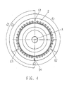
- Fig. 4 shows a schematic plan view of a vacuum roller 2, wherein in the lateral surface of the vacuum roller 2, the counter-elements 61, 62, 63 and 64 are introduced parallel to the axis of rotation A of the vacuum roller 2.
- the distance of the counter-elements 61, 62 and 63 to each other is chosen so that they enclose an angle of 120 ° (63 ⁇ , 62 ⁇ , 61 ⁇ ).
- the fourth counter element 64 is also introduced parallel to the axis of rotation of the vacuum roller A in the lateral surface of the vacuum roller 2, wherein the fourth counter element 64 with the counter element 61 forms an angle 64 ⁇ of 180 °.
- the loadable gripper cylinders 7 may be those which either two corresponding to the circumference of the vacuum roller labels, or three the two-fold the circumference of the vacuum roller corresponding, or four four and a half times the circumference of the vacuum roller corresponding, or six corresponding to the one-and-a-half perimeter of the vacuum roller labels can accommodate.
- Fig. 5 shows a schematic plan view of the cutting device 1 and the gluing unit 17.
- the withdrawn from the label tape rolls 14 label tape is fed via the guide roller 20 and the roller pair 19 of the cutting device 1.
- the label tape is on the vacuum roller 2, which rotates in the direction of the arrow 33, and is cut by the separating element 3 according to the Thomasmarken- or printed image.
- a gluing unit 17 is required.
- the gluing unit 17 consists of a glue tank 36, a glue heating 37, a gluing bar 38, an glue pump 40 and quick-action clamping elements 39.
- the hot glue added to the glue tank 36 and liquefied via the glue heating 37 is thus pumped out of the glue tank 36 via the glue pump 40 and the glue roller 18 fed to the lateral surface.
- the glue bar 38 is delivered to the glue roller 18 so close that during the rotation of the glue roller 18 it removes the superfluous glue and only a thin glue film remains on the jacket surface of the glue roller 18.
- the glue remaining on the glue bar 38 is supplied to the glue tank 36 again, thus creating a glue circulation.
- the gluing unit base plate 16 can be attached as a whole to the labeling unit 12. For this purpose, it is applied to two strips of the labeling unit 12, not shown here, and fastened with a quick-release element 39 on one of these two strips. By releasing the quick-release element 39, the gluing unit base plate 16 with all its components can be removed from the labeling unit and replaced by another gluing unit.
Priority Applications (6)
| Application Number | Priority Date | Filing Date | Title |
|---|---|---|---|
| DE200750003415 DE502007003415D1 (de) | 2007-09-03 | 2007-09-03 | Etikettiervorrichtung |
| EP20070017190 EP2042437B1 (fr) | 2007-09-03 | 2007-09-03 | Dispositif d'étiquetage |
| JP2008225045A JP2009057113A (ja) | 2007-09-03 | 2008-09-02 | 全周ラベル貼り装置 |
| CN201410141091.0A CN103910106A (zh) | 2007-09-03 | 2008-09-03 | 标签机 |
| CNA2008102158739A CN101407256A (zh) | 2007-09-03 | 2008-09-03 | 标签机 |
| US12/203,637 US8763666B2 (en) | 2007-09-03 | 2008-09-03 | All-round labelling apparatus |
Applications Claiming Priority (1)
| Application Number | Priority Date | Filing Date | Title |
|---|---|---|---|
| EP20070017190 EP2042437B1 (fr) | 2007-09-03 | 2007-09-03 | Dispositif d'étiquetage |
Publications (2)
| Publication Number | Publication Date |
|---|---|
| EP2042437A1 true EP2042437A1 (fr) | 2009-04-01 |
| EP2042437B1 EP2042437B1 (fr) | 2010-04-07 |
Family
ID=38983317
Family Applications (1)
| Application Number | Title | Priority Date | Filing Date |
|---|---|---|---|
| EP20070017190 Active EP2042437B1 (fr) | 2007-09-03 | 2007-09-03 | Dispositif d'étiquetage |
Country Status (5)
| Country | Link |
|---|---|
| US (1) | US8763666B2 (fr) |
| EP (1) | EP2042437B1 (fr) |
| JP (1) | JP2009057113A (fr) |
| CN (2) | CN103910106A (fr) |
| DE (1) | DE502007003415D1 (fr) |
Cited By (6)
| Publication number | Priority date | Publication date | Assignee | Title |
|---|---|---|---|---|
| EP2196397A2 (fr) | 2008-12-12 | 2010-06-16 | Krones AG | Dispositif et procédé d'application d'étiquettes mises à disposition en tant que matériaux pour rouleaux sur des récipients |
| EP2279954A2 (fr) | 2009-07-29 | 2011-02-02 | Krones AG | Dispositif de coupe et procédé de coupe pour couper des étiquettes et dispositif d'étiquetage |
| DE102009040346A1 (de) | 2009-09-09 | 2011-03-10 | Krones Ag | Etikettiervorrichtung und Etikettierverfahren zum Etikettieren von Behältnissen sowie Anlage zur Behandlung von Behältnissen |
| WO2012090233A1 (fr) * | 2010-12-30 | 2012-07-05 | Sidel S.P.A. | Groupe d'étiquetage |
| WO2017205195A1 (fr) * | 2016-05-24 | 2017-11-30 | The Procter & Gamble Company | Enclume rotative |
| US11292016B2 (en) | 2018-03-16 | 2022-04-05 | The Procter & Gamble Company | Nozzle assembly used to manufacture absorbent articles |
Families Citing this family (8)
| Publication number | Priority date | Publication date | Assignee | Title |
|---|---|---|---|---|
| DE102011004976B4 (de) * | 2011-03-02 | 2023-09-07 | Krones Aktiengesellschaft | Etikettiervorrichtung und Etikettierverfahren |
| ITTO20110444A1 (it) * | 2011-05-19 | 2012-11-20 | Tecnau Srl | "equipaggiamento per perforazioni trasversali di lunghezze variabili su moduli continui in movimento" |
| CN102975917A (zh) * | 2012-11-30 | 2013-03-20 | 吴江忆久纺织有限公司 | 一种纺织用贴标签装置 |
| CN103395274B (zh) * | 2013-07-31 | 2015-05-06 | 苏州凯蒂亚半导体制造设备有限公司 | 滚筒式贴合机的胶粘膜贴合装置 |
| CN104723653B (zh) * | 2015-04-03 | 2017-01-04 | 苏州博众精工科技有限公司 | 一种撕手机保护膜机构 |
| CN109367943B (zh) * | 2018-12-03 | 2023-09-01 | 上海金自天正信息技术有限公司 | 一种机器人手持式钢坯贴标装置、系统以及方法 |
| CN110902066B (zh) * | 2019-12-04 | 2024-03-12 | 长春知和智能包装设备有限公司 | 重桶旋转式贴标机 |
| CN111332574A (zh) * | 2020-03-10 | 2020-06-26 | 深圳通达电子有限公司 | 一种自动贴码扫码的系统 |
Citations (4)
| Publication number | Priority date | Publication date | Assignee | Title |
|---|---|---|---|---|
| EP0943404A2 (fr) * | 1998-03-17 | 1999-09-22 | Mitsubishi Heavy Industries, Ltd. | Dispositif de lubrification pour machines rotatives d'estampage |
| US20010054343A1 (en) * | 2000-06-27 | 2001-12-27 | Sasib Labeling Machinery S.P.A. | Cutting roller in a labeling machine with the continuous introduction of a reeled film of labels |
| DE69822238T2 (de) | 1997-03-18 | 2005-04-14 | Sig Alfa S.P.A. | Schneidevorrichtung für eine Etikettiermaschine |
| DE202005002793U1 (de) | 2005-02-22 | 2005-04-21 | Krones Ag | Rundumetikettiervorrichtung |
Family Cites Families (10)
| Publication number | Priority date | Publication date | Assignee | Title |
|---|---|---|---|---|
| US3767514A (en) * | 1972-01-25 | 1973-10-23 | F Blossom | Labeling and feeding machine |
| US3977617A (en) * | 1973-07-12 | 1976-08-31 | Salmon Marion B | Film winding and perforating apparatus |
| US5711199A (en) * | 1997-01-06 | 1998-01-27 | The Coe Manufacturing Company | Clipping trash gate for trimming strip of sheet material |
| US6173633B1 (en) * | 1999-04-09 | 2001-01-16 | Mclaughlin James | Variable length rotary cutting system |
| JP3381845B2 (ja) * | 1999-07-08 | 2003-03-04 | 日立金属株式会社 | 被削性に優れた低熱膨張鋳鋼 |
| US6347657B1 (en) * | 1999-09-08 | 2002-02-19 | B & H Manufacturing Company, Inc. | Lightweight vacuum drum |
| GB9921463D0 (en) * | 1999-09-11 | 1999-11-10 | Molins Plc | Cutting apparatus |
| US7299729B2 (en) * | 2001-05-23 | 2007-11-27 | Cox William A | Rotary die module |
| JP4618408B2 (ja) * | 2004-05-31 | 2011-01-26 | 東洋製罐株式会社 | ロータリーカッター |
| US20070044613A1 (en) * | 2005-09-01 | 2007-03-01 | Robert Cohn | Rotary cutting device |
-
2007
- 2007-09-03 EP EP20070017190 patent/EP2042437B1/fr active Active
- 2007-09-03 DE DE200750003415 patent/DE502007003415D1/de active Active
-
2008
- 2008-09-02 JP JP2008225045A patent/JP2009057113A/ja active Pending
- 2008-09-03 CN CN201410141091.0A patent/CN103910106A/zh active Pending
- 2008-09-03 US US12/203,637 patent/US8763666B2/en active Active
- 2008-09-03 CN CNA2008102158739A patent/CN101407256A/zh active Pending
Patent Citations (4)
| Publication number | Priority date | Publication date | Assignee | Title |
|---|---|---|---|---|
| DE69822238T2 (de) | 1997-03-18 | 2005-04-14 | Sig Alfa S.P.A. | Schneidevorrichtung für eine Etikettiermaschine |
| EP0943404A2 (fr) * | 1998-03-17 | 1999-09-22 | Mitsubishi Heavy Industries, Ltd. | Dispositif de lubrification pour machines rotatives d'estampage |
| US20010054343A1 (en) * | 2000-06-27 | 2001-12-27 | Sasib Labeling Machinery S.P.A. | Cutting roller in a labeling machine with the continuous introduction of a reeled film of labels |
| DE202005002793U1 (de) | 2005-02-22 | 2005-04-21 | Krones Ag | Rundumetikettiervorrichtung |
Cited By (11)
| Publication number | Priority date | Publication date | Assignee | Title |
|---|---|---|---|---|
| EP2196397A2 (fr) | 2008-12-12 | 2010-06-16 | Krones AG | Dispositif et procédé d'application d'étiquettes mises à disposition en tant que matériaux pour rouleaux sur des récipients |
| DE102008061976A1 (de) * | 2008-12-12 | 2010-06-17 | Krones Ag | Vorrichtung und Verfahren zum Anbringen von als Rollenmaterial zur Verfügung gestellter Etiketten auf Behälter |
| EP2279954A2 (fr) | 2009-07-29 | 2011-02-02 | Krones AG | Dispositif de coupe et procédé de coupe pour couper des étiquettes et dispositif d'étiquetage |
| DE102009035269A1 (de) | 2009-07-29 | 2011-02-03 | Krones Ag | Schneideinrichtung und Schneidverfahren zum Schneiden von Etiketten sowie Etikettiervorrichtung |
| US9003935B2 (en) | 2009-07-29 | 2015-04-14 | Krones Ag | Cutting device and cutting method for cutting labels, and labelling apparatus |
| DE102009040346A1 (de) | 2009-09-09 | 2011-03-10 | Krones Ag | Etikettiervorrichtung und Etikettierverfahren zum Etikettieren von Behältnissen sowie Anlage zur Behandlung von Behältnissen |
| EP2295326A1 (fr) | 2009-09-09 | 2011-03-16 | Krones AG | Dispositif d'étiquetage et procédé d'étiquetage pour étiqueter des récipients |
| US9598199B2 (en) | 2009-09-09 | 2017-03-21 | Krones Ag | Labelling apparatus and labelling process for the labelling of containers as well as plant for the treatment of containers |
| WO2012090233A1 (fr) * | 2010-12-30 | 2012-07-05 | Sidel S.P.A. | Groupe d'étiquetage |
| WO2017205195A1 (fr) * | 2016-05-24 | 2017-11-30 | The Procter & Gamble Company | Enclume rotative |
| US11292016B2 (en) | 2018-03-16 | 2022-04-05 | The Procter & Gamble Company | Nozzle assembly used to manufacture absorbent articles |
Also Published As
| Publication number | Publication date |
|---|---|
| JP2009057113A (ja) | 2009-03-19 |
| US20090071608A1 (en) | 2009-03-19 |
| US8763666B2 (en) | 2014-07-01 |
| CN103910106A (zh) | 2014-07-09 |
| DE502007003415D1 (de) | 2010-05-20 |
| CN101407256A (zh) | 2009-04-15 |
| EP2042437B1 (fr) | 2010-04-07 |
Similar Documents
| Publication | Publication Date | Title |
|---|---|---|
| EP2042437B1 (fr) | Dispositif d'étiquetage | |
| DE202005002793U1 (de) | Rundumetikettiervorrichtung | |
| EP2505507B1 (fr) | Dispositif destinés à l'application de colle | |
| DE60131885T2 (de) | Vorschubsystem für bahnförmiges material und vorrichtung zum auftragen von bahnförmigem material | |
| EP3044103B1 (fr) | Dispositif pour le nettoyage d'un rouleau d'encollage d'une unité d'étiquetage | |
| EP2279954B1 (fr) | Dispositif de coupe et procédé de coupe pour couper des étiquettes et dispositif d'étiquetage | |
| WO2017001075A1 (fr) | Rouleau encolleur à zone d'encollage limitée | |
| EP3237290B1 (fr) | Dispositif et procede pour l'etiquetage des paquets seuls | |
| EP2495179A2 (fr) | Dispositif d'étiquetage | |
| EP2229324B1 (fr) | Procédé d'étiquetage de récipients et poste d'étiquetage | |
| EP3533719B1 (fr) | Dispositif d'étiquetage destiné à l'application des étiquettes sur des récipients | |
| DE102007009484A1 (de) | Etikettieraggregat sowie Etikettiermaschine | |
| EP1724196B1 (fr) | Machine d'étiquetage pour récipients | |
| DE19716079A1 (de) | Verfahren zum Etikettieren von Behältern, insbesondere Flaschen, sowie Etikettiermaschine | |
| DE102010000182A1 (de) | Leimwalze zum Auftrag von Leim auf Etiketten, Verfahren zum Etikettieren von Artikeln und Herstellungsverfahren für eine Leimwalze | |
| DE102015212143A1 (de) | Vorrichtung und Verfahren zum Etikettieren von Behältern | |
| DE69933546T2 (de) | Verarbeitung von zuschnitten bei der herstellung von verpackungen | |
| EP2196397A2 (fr) | Dispositif et procédé d'application d'étiquettes mises à disposition en tant que matériaux pour rouleaux sur des récipients | |
| EP0135935B1 (fr) | Machine à envelopper | |
| EP3919397B1 (fr) | Cylindre segmenté de transfert de vide | |
| EP0014858B1 (fr) | Procédé et dispositif pour appliquer des rubans d'ouverture ou analogues sur une feuille de matériau d'empaquetage | |
| WO2017025218A1 (fr) | Procédé et dispositif pour raccorder des étiquettes tubulaires | |
| EP2743195A1 (fr) | Étiqueteuse à colle humide | |
| DE19821253A1 (de) | Beleimungsstation für eine Etikettiermaschine sowie Etikettiermaschine | |
| DE3242927C2 (de) | Etikettiervorrichtung |
Legal Events
| Date | Code | Title | Description |
|---|---|---|---|
| PUAI | Public reference made under article 153(3) epc to a published international application that has entered the european phase |
Free format text: ORIGINAL CODE: 0009012 |
|
| 17P | Request for examination filed |
Effective date: 20080227 |
|
| AK | Designated contracting states |
Kind code of ref document: A1 Designated state(s): AT BE BG CH CY CZ DE DK EE ES FI FR GB GR HU IE IS IT LI LT LU LV MC MT NL PL PT RO SE SI SK TR |
|
| AX | Request for extension of the european patent |
Extension state: AL BA HR MK RS |
|
| GRAP | Despatch of communication of intention to grant a patent |
Free format text: ORIGINAL CODE: EPIDOSNIGR1 |
|
| GRAS | Grant fee paid |
Free format text: ORIGINAL CODE: EPIDOSNIGR3 |
|
| AKX | Designation fees paid |
Designated state(s): DE FR GB IT |
|
| GRAA | (expected) grant |
Free format text: ORIGINAL CODE: 0009210 |
|
| AK | Designated contracting states |
Kind code of ref document: B1 Designated state(s): DE FR GB IT |
|
| REG | Reference to a national code |
Ref country code: GB Ref legal event code: FG4D Free format text: NOT ENGLISH |
|
| REF | Corresponds to: |
Ref document number: 502007003415 Country of ref document: DE Date of ref document: 20100520 Kind code of ref document: P |
|
| PLBE | No opposition filed within time limit |
Free format text: ORIGINAL CODE: 0009261 |
|
| STAA | Information on the status of an ep patent application or granted ep patent |
Free format text: STATUS: NO OPPOSITION FILED WITHIN TIME LIMIT |
|
| 26N | No opposition filed |
Effective date: 20110110 |
|
| GBPC | Gb: european patent ceased through non-payment of renewal fee |
Effective date: 20110903 |
|
| PG25 | Lapsed in a contracting state [announced via postgrant information from national office to epo] |
Ref country code: GB Free format text: LAPSE BECAUSE OF NON-PAYMENT OF DUE FEES Effective date: 20110903 |
|
| REG | Reference to a national code |
Ref country code: FR Ref legal event code: PLFP Year of fee payment: 10 |
|
| REG | Reference to a national code |
Ref country code: FR Ref legal event code: PLFP Year of fee payment: 11 |
|
| REG | Reference to a national code |
Ref country code: FR Ref legal event code: PLFP Year of fee payment: 12 |
|
| P01 | Opt-out of the competence of the unified patent court (upc) registered |
Effective date: 20230523 |
|
| PGFP | Annual fee paid to national office [announced via postgrant information from national office to epo] |
Ref country code: IT Payment date: 20230810 Year of fee payment: 17 |
|
| PGFP | Annual fee paid to national office [announced via postgrant information from national office to epo] |
Ref country code: FR Payment date: 20230808 Year of fee payment: 17 Ref country code: DE Payment date: 20230802 Year of fee payment: 17 |