EP2042437A1 - Labelling device - Google Patents
Labelling device Download PDFInfo
- Publication number
- EP2042437A1 EP2042437A1 EP20070017190 EP07017190A EP2042437A1 EP 2042437 A1 EP2042437 A1 EP 2042437A1 EP 20070017190 EP20070017190 EP 20070017190 EP 07017190 A EP07017190 A EP 07017190A EP 2042437 A1 EP2042437 A1 EP 2042437A1
- Authority
- EP
- European Patent Office
- Prior art keywords
- machine according
- rotating
- vacuum roller
- labeling
- labeling machine
- Prior art date
- Legal status (The legal status is an assumption and is not a legal conclusion. Google has not performed a legal analysis and makes no representation as to the accuracy of the status listed.)
- Granted
Links
- 238000002372 labelling Methods 0.000 title claims abstract description 60
- 238000005520 cutting process Methods 0.000 claims abstract description 65
- 238000012545 processing Methods 0.000 claims abstract description 3
- 239000003292 glue Substances 0.000 claims description 35
- 238000004026 adhesive bonding Methods 0.000 claims description 20
- 229910052782 aluminium Inorganic materials 0.000 claims description 9
- XAGFODPZIPBFFR-UHFFFAOYSA-N aluminium Chemical compound [Al] XAGFODPZIPBFFR-UHFFFAOYSA-N 0.000 claims description 9
- 239000000463 material Substances 0.000 claims description 8
- 239000000853 adhesive Substances 0.000 claims description 5
- 230000001070 adhesive effect Effects 0.000 claims description 5
- 238000010438 heat treatment Methods 0.000 claims description 3
- 229910000831 Steel Inorganic materials 0.000 claims description 2
- 239000010959 steel Substances 0.000 claims description 2
- 229910003460 diamond Inorganic materials 0.000 claims 1
- 239000010432 diamond Substances 0.000 claims 1
- 229910001220 stainless steel Inorganic materials 0.000 claims 1
- 239000010935 stainless steel Substances 0.000 claims 1
- 230000002093 peripheral effect Effects 0.000 description 8
- 238000011161 development Methods 0.000 description 5
- 230000008901 benefit Effects 0.000 description 4
- 230000008859 change Effects 0.000 description 3
- 238000013461 design Methods 0.000 description 3
- 238000000034 method Methods 0.000 description 3
- 230000008569 process Effects 0.000 description 3
- 238000012546 transfer Methods 0.000 description 3
- 238000004140 cleaning Methods 0.000 description 2
- 229910052751 metal Inorganic materials 0.000 description 2
- 239000002184 metal Substances 0.000 description 2
- 230000009467 reduction Effects 0.000 description 2
- 239000004831 Hot glue Substances 0.000 description 1
- 230000015572 biosynthetic process Effects 0.000 description 1
- 238000012937 correction Methods 0.000 description 1
- 230000008878 coupling Effects 0.000 description 1
- 238000010168 coupling process Methods 0.000 description 1
- 238000005859 coupling reaction Methods 0.000 description 1
- 230000007423 decrease Effects 0.000 description 1
- 239000011521 glass Substances 0.000 description 1
- 239000012943 hotmelt Substances 0.000 description 1
- 238000005192 partition Methods 0.000 description 1
- 238000004080 punching Methods 0.000 description 1
- 238000000926 separation method Methods 0.000 description 1
- 239000000725 suspension Substances 0.000 description 1
- 230000001360 synchronised effect Effects 0.000 description 1
- 238000011144 upstream manufacturing Methods 0.000 description 1
- 238000004804 winding Methods 0.000 description 1
Images


Classifications
-
- B—PERFORMING OPERATIONS; TRANSPORTING
- B65—CONVEYING; PACKING; STORING; HANDLING THIN OR FILAMENTARY MATERIAL
- B65C—LABELLING OR TAGGING MACHINES, APPARATUS, OR PROCESSES
- B65C9/00—Details of labelling machines or apparatus
- B65C9/08—Label feeding
- B65C9/18—Label feeding from strips, e.g. from rolls
- B65C9/1803—Label feeding from strips, e.g. from rolls the labels being cut from a strip
- B65C9/1815—Label feeding from strips, e.g. from rolls the labels being cut from a strip and transferred by suction means
- B65C9/1819—Label feeding from strips, e.g. from rolls the labels being cut from a strip and transferred by suction means the suction means being a vacuum drum
-
- B—PERFORMING OPERATIONS; TRANSPORTING
- B65—CONVEYING; PACKING; STORING; HANDLING THIN OR FILAMENTARY MATERIAL
- B65C—LABELLING OR TAGGING MACHINES, APPARATUS, OR PROCESSES
- B65C9/00—Details of labelling machines or apparatus
- B65C9/08—Label feeding
- B65C9/18—Label feeding from strips, e.g. from rolls
- B65C9/1803—Label feeding from strips, e.g. from rolls the labels being cut from a strip
- B65C9/183—Label feeding from strips, e.g. from rolls the labels being cut from a strip and transferred by gripping means or feeding rollers
-
- B—PERFORMING OPERATIONS; TRANSPORTING
- B65—CONVEYING; PACKING; STORING; HANDLING THIN OR FILAMENTARY MATERIAL
- B65C—LABELLING OR TAGGING MACHINES, APPARATUS, OR PROCESSES
- B65C9/00—Details of labelling machines or apparatus
- B65C9/08—Label feeding
- B65C9/18—Label feeding from strips, e.g. from rolls
- B65C9/1803—Label feeding from strips, e.g. from rolls the labels being cut from a strip
- B65C2009/1834—Details of cutting means
- B65C2009/1838—Cutting drum
- B65C2009/1842—Temperature control
-
- B—PERFORMING OPERATIONS; TRANSPORTING
- B65—CONVEYING; PACKING; STORING; HANDLING THIN OR FILAMENTARY MATERIAL
- B65C—LABELLING OR TAGGING MACHINES, APPARATUS, OR PROCESSES
- B65C9/00—Details of labelling machines or apparatus
- B65C9/08—Label feeding
- B65C9/18—Label feeding from strips, e.g. from rolls
- B65C9/1803—Label feeding from strips, e.g. from rolls the labels being cut from a strip
- B65C2009/1834—Details of cutting means
- B65C2009/1857—Details of cutting means two co-acting knifes
-
- Y—GENERAL TAGGING OF NEW TECHNOLOGICAL DEVELOPMENTS; GENERAL TAGGING OF CROSS-SECTIONAL TECHNOLOGIES SPANNING OVER SEVERAL SECTIONS OF THE IPC; TECHNICAL SUBJECTS COVERED BY FORMER USPC CROSS-REFERENCE ART COLLECTIONS [XRACs] AND DIGESTS
- Y10—TECHNICAL SUBJECTS COVERED BY FORMER USPC
- Y10T—TECHNICAL SUBJECTS COVERED BY FORMER US CLASSIFICATION
- Y10T156/00—Adhesive bonding and miscellaneous chemical manufacture
- Y10T156/12—Surface bonding means and/or assembly means with cutting, punching, piercing, severing or tearing
- Y10T156/1317—Means feeding plural workpieces to be joined
- Y10T156/1322—Severing before bonding or assembling of parts
- Y10T156/1339—Delivering cut part in sequence to serially conveyed articles
-
- Y—GENERAL TAGGING OF NEW TECHNOLOGICAL DEVELOPMENTS; GENERAL TAGGING OF CROSS-SECTIONAL TECHNOLOGIES SPANNING OVER SEVERAL SECTIONS OF THE IPC; TECHNICAL SUBJECTS COVERED BY FORMER USPC CROSS-REFERENCE ART COLLECTIONS [XRACs] AND DIGESTS
- Y10—TECHNICAL SUBJECTS COVERED BY FORMER USPC
- Y10T—TECHNICAL SUBJECTS COVERED BY FORMER US CLASSIFICATION
- Y10T83/00—Cutting
- Y10T83/465—Cutting motion of tool has component in direction of moving work
- Y10T83/4766—Orbital motion of cutting blade
- Y10T83/4795—Rotary tool
- Y10T83/483—With cooperating rotary cutter or backup
Definitions
- the invention relates to a labeling machine according to the preamble of claim 1.
- endless label tapes are usually used that have been wound onto a roll core into a label roll.
- This type of labeling allows a possible uninterrupted labeling, as well as several label rolls are mounted in a memory, which are then transferred seamlessly into the labeling when needed. This allows high-speed labeling operations.
- the labeling device is known DE202005002793U1 which, inter alia, provides a high speed cutter for endless label belts from roll processing labeling machines, the cutter comprising a rotating vacuum roll and a rotating separator.
- the vacuum roll and the separating element are each equipped with their own drives.
- this device has the disadvantage that the wear of the cutting element attached to the cutting tools is very high, since the cooperating elements expand in high-speed operation and thus the set tolerances can no longer be met.
- Containers can u. a. Cans, PET bottles, glass bottles, cans, jars or tubs.
- the preferably designed as a rotary labeller has preferably a linear container feed, at the end of a Einteilschnecke or a Einteilstern (eg sawtooth star) provides for the division-oriented feeding of the container to the Etikettier Scheme.
- a transfer element to the container removal area.
- the labeling area can be designed differently. It is possible, for example, for the items to be labeled Support plates, such as turntables are or that they are ground-free, for example, hung at the mouth or transported seized.
- the labeling unit for wrap-around labels consists of at least one label roll, a label feeder, a cutting device, a gripper cylinder and a gluing unit, wherein the label strip to be separated from the label roll is withdrawn and fed via the label feed the vacuum roller and the cutting device.
- the transport of the label strip on the vacuum roller preferably takes place without slippage, but in certain cases (eg for cutting position correction), it can also be carried out with slippage.
- the label tape which is located on the vacuum roller, is severed by the cutting device.
- the thus isolated labels are handed over to the gripper cylinder, which provides them with a start and end adhesive strip or a more or less completely formed glue film when passing the gluing unit.
- the gripper cylinder passes the label to the article to be labeled, the label being wound up by the self-rotation of the article. Then the EndleimstMail is glued to the article or overlapping with the label.
- the cutting device is preferably formed by a rotating vacuum roller and a rotating separating element, wherein the separating element has at least one separating tool on its circumference.
- the cutting tool is preferably a cutting tool, in particular a cutting blade, wherein the formation of the cutting tool can also be carried out as a punching tool.
- the cutting device is preferably held by a carrying device which has at least one bottom part and a Cover part has.
- the carrying device is designed such that the vacuum roller and the rotating separating element are mounted directly or indirectly in the carrying device. Between the bottom part and the lid part connecting elements can be attached, which provide a mechanical, non-positive coupling.
- the bottom part and the lid part are preferably each formed in one piece and have an average thermal expansion coefficient which is approximately equal. There is often talk here of the mean thermal expansion coefficient. This refers to the effective coefficient of thermal expansion that actually exists. It may be, for example, that the bottom part is constructed of different materials, each having different coefficients of expansion. With the mean coefficient of thermal expansion, therefore, the practically existing extent of the various materials, for example the bottom part, should be indicated.
- the support means is formed so that its average coefficient of thermal expansion corresponds to the average coefficient of thermal expansion of the vacuum roller and the rotating separating element.
- the bottom part and the cover part of the support device made of the same material, so that this results in an approximately equal coefficient of thermal expansion.
- the support device and the vacuum roller and the cutting blade are constructed of the same basic materials, thereby resulting in an approximately equal coefficient of thermal expansion.
- a preferred material for said parts is aluminum.
- the cylindrical basic structure of the vacuum roller consists mainly of aluminum as well as the rotating partition, this does not mean that the addressed elements consist only of aluminum.
- Another embodiment of the invention is that the separating element, the vacuum roller and the supporting device made of steel, so that here there is a substantially equal coefficient of thermal expansion.
- counter-elements are mounted on the vacuum roller, with which the cutting tool for cutting the label can be brought into contact, wherein the counter-elements are formed of metal strips.
- the cutting operation of the label is carried out by the contact of separating tool and counter element.
- the metal strips are preferably introduced into the vacuum cylinder so that they do not protrude from the cylinder surface.
- the rotating separating element has at least two separating tools, but preferably exactly two separating tools for severing the label.
- the rotational speed of the separator decreases with the same performance of the labeling, since from one label cut to the next no 360 ° rotation, but with two cutting tools a rotation of 180 ° and four cutting tools only a rotation of the separating element of 90 ° must be made.
- the rotating vacuum roller contains two counter-elements, on which the cutting tool can perform the cut through the label.
- the cutting tool can perform the cut through the label.
- the rotating vacuum roller contains two counter-elements, on which the cutting tool can perform the cut through the label.
- the rotating vacuum roller contains two counter-elements, on which the cutting tool can perform the cut through the label.
- the rotating vacuum roller contains two counter-elements, on which the cutting tool can perform the cut through the label.
- the rotating vacuum roller is located on the rotating vacuum roller at least four, more preferably exactly four counter-elements.
- the counter-elements integrated in the manner in the rotating vacuum roller that three counter-elements each with a distance of 120 ° and that the fourth counter-element is attached to any of the three counter-elements with a distance of 180 °, so there is the advantage that with a rotating vacuum roll can be produced label lengths that correspond to the simple circumference, two-thirds of the circumference, one and a half times the circumference or
- a particularly flexible arrangement with respect to the lengths of label to be produced arises when the entire circumference of the vacuum roller is designed as a counter element, i. the surface material of the vacuum roller corresponds to that of the counter-elements.
- the cutting tool can be engaged at any position with the rotating vacuum roll for the purpose of cutting. An alignment of the vacuum roller to the cutting tool is therefore not necessary.
- both the rotating vacuum roller and the rotating separating element are each equipped with their own motor drive, with the drive particularly preferably being a servo drive.
- the drive particularly preferably being a servo drive.
- the equipment of the separating element and the vacuum roller, each with its own drive has the advantage that as flexible as possible adapted to the present situation cutting process can be used. If e.g. the separating element has two separating tools, but one is worn, so it is possible to rotate the separator from one to the next cut by 360 °, so that the worn cutting tool is no longer used. This is advantageous because then a change of the separating element can be made when the machine is serviced anyway. Additional interruptions can thus be minimized to a necessary level.
- the peripheral speeds of the separating element and the vacuum roller which may well differ during a revolution, so matched to one another that they are the same at the time of cutting the label.
- the rotating separating element has one or two separating tools on its circumference, then it preferably has a substantially diamond-shaped shape, at the flattened pointed ends of which or the separating tools are attached.
- This embodiment has the advantage that at high peripheral speed of the separating element low masses must be moved.
- the rotating separator more as two separating tools, for example four, the rotating separating element can be formed, for example, as a substantially rectangular structure, on the flattened edges of which the separating tools are respectively fastened.
- Another possible arrangement consists in the cylindrical configuration of the separating element, on the lateral surface of which the separating tools are fastened.
- the cutting tool is preferably spring-mounted in the separating element.
- the gluing unit belonging to the labeling unit of the labeling machine consists at least of a tank, a heater, a glue roller and an adhesive strip, wherein the gluing unit is designed as a complete structural unit which can be exchanged as a whole.
- This hotmelt unit which can be replaced as a whole, has the advantage that, when the label adhesive is changed, the cleaning of the tank, the glue roller and the glue bar as well as the cleaning of the adhesive guides can only take place after removal of the gluing unit from the labeling unit, whereby the downtime of the labeling machine can be considerably reduced ,
- the gluing unit is fastened with the aid of quick-release elements on the labeling unit, whereby an even faster changing process is made possible.
- FIG. 1 shows a schematic plan view of a labeling machine, which allows a continuous high-performance application of wrap-around labels on a single-line row continuously supplied bottles 10.
- the bottles 10 transporting elements moving through the machine are continuously drivable with respect to each other in terms of speed and position.
- a labeling unit 12 for applying wrap-around labels.
- the labeling unit 12 has two label roll receptacles 14 with an intermediate splicing station 15, a cutting device 1, a gluing unit 17 and a gripper cylinder 7 for transferring a pre-cut label glued to its leading and trailing edges onto a bottle 10 passing by.
- a brought up by the feed conveyor 24 bottle 10 is introduced in connection with the laterally arranged Einteilschnecke 23 positionally correct in the inlet starwheel 25 and pushed by this in cooperation with the opposite guide arc 22 in continuous motion on a turntable 26 of the rotating carousel 27.
- the bottle 10 is rotatably clamped by an unillustrated, relative to the turntable 26 controlled raised and lowered centering axially on the turntable 26 with this and brought by the orbital motion of the carousel 27 tangentially to the gripper cylinder 17 of the labeling unit 12.
- the label tape is withdrawn controlled from one of the label tape rolls 14 and guided past a print mark or print image sensor which is not shown here, and cut into the printed image or the cut marks in the cutting device 1 connected to the sensor.
- the separated label which is located during the cutting process with the printed image to the outside on the rotating vacuum roller 2, after the separation process with the passed vacuum-operated gripper cylinder 7, from where it is guided past the glue roller 18 with the back to the outside and is provided with a glue strip at the beginning and at the end.
- This provided with the beginning or EindleimstMail label is tangentially the carousel 27 on which the bottles 10 are supplied.
- the initial glue strip is brought into contact with the bottle 10 and by rotating the bottle 10 about its own axis the label is wound up, whereby the end glue strip is glued either overlapping or edge to edge with the beginning of the label.
- the described attachment of the label takes place during a continuous forward movement of the carousel 27th
- the labeled bottle 10 After passing through the labeling unit 12 and after completion of the winding process, the labeled bottle 10 reaches the outlet starwheel 8 in the further course and is transferred to the outlet conveyor 9.
- FIG. 2 shows a detailed view of the cutting device 1 of the labeling unit 12.
- the label tape which is subtracted from the label tape rolls 14, the cutter 1 is fed tangentially in the direction of arrow 31 of the vacuum roller 2.
- the peripheral speed of the rotating vacuum roller 2 is equal to the feed speed of the label tape, so that the transport of the label tape on the vacuum roller 2 is frictionally without slippage.
- a print-image or cut-mark sensor not shown here, scans the label tape with respect to the points to be cut and forwards its information directly to the drive unit of the separating element 3 and / or the vacuum roller 2.
- a program control can determine the time of cutting and thus the Set peripheral speed of the separating element 3 and / or the vacuum roller 2.
- the peripheral speed of the cutting tool 4 in the rotating separator 3 is equal to the peripheral speed of the vacuum roller 2 and thus also the transport speed of the label tape.
- the bottom part 29 of the cutting device 1 can be seen, wherein the parts mainly made of aluminum separating element 3 and vacuum roller 2 are rotatably mounted in the bottom part 29.
- the connecting elements 30a serve to connect the bottom part 29 and the lid part 30, not shown here, to each other.
- the aluminum components in the cutting device 1 heat up, resulting in thermal expansion.
- the diameter Dv of the vacuum roller 2 becomes the same as the diameter Dt of the separating element 3.
- the support means 28 is also made of aluminum, so that for the bottom part 29 due to the approximately equal thermal expansion coefficient results in an expansion in the direction of A1 and A2, which approximately eliminates the reduction in distance between the vacuum roller 2 and 3 separating.
- the lid part, not shown here, which is also made of aluminum is also made of aluminum.
- FIG. 3 shows a perspective view of the cutting device 1 of the labeling unit 12.
- the zu cutting label tape is fed to the vacuum roller 2 in the direction of the arrow 31.
- the vacuum roller 2 and the separating element 3 are driven by their own drive units, in which case only the motor drive unit 5 of the separating element 3 is shown, in such a way that the separating tool 4 engages with the counter element 6 on the vacuum roller 2 at the time of cutting the label , wherein at this moment the peripheral speed of the separating element 3 and the vacuum roller 2 are the same.
- the cutting tool 4 is resiliently mounted in the separating element 3 in order to be able to separate wear-resistant for the separating tool and gently for the label when engaging with the counter-element 6.
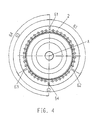
- Fig. 4 shows a schematic plan view of a vacuum roller 2, wherein in the lateral surface of the vacuum roller 2, the counter-elements 61, 62, 63 and 64 are introduced parallel to the axis of rotation A of the vacuum roller 2.
- the distance of the counter-elements 61, 62 and 63 to each other is chosen so that they enclose an angle of 120 ° (63 ⁇ , 62 ⁇ , 61 ⁇ ).
- the fourth counter element 64 is also introduced parallel to the axis of rotation of the vacuum roller A in the lateral surface of the vacuum roller 2, wherein the fourth counter element 64 with the counter element 61 forms an angle 64 ⁇ of 180 °.
- the loadable gripper cylinders 7 may be those which either two corresponding to the circumference of the vacuum roller labels, or three the two-fold the circumference of the vacuum roller corresponding, or four four and a half times the circumference of the vacuum roller corresponding, or six corresponding to the one-and-a-half perimeter of the vacuum roller labels can accommodate.
- Fig. 5 shows a schematic plan view of the cutting device 1 and the gluing unit 17.
- the withdrawn from the label tape rolls 14 label tape is fed via the guide roller 20 and the roller pair 19 of the cutting device 1.
- the label tape is on the vacuum roller 2, which rotates in the direction of the arrow 33, and is cut by the separating element 3 according to the Thomasmarken- or printed image.
- a gluing unit 17 is required.
- the gluing unit 17 consists of a glue tank 36, a glue heating 37, a gluing bar 38, an glue pump 40 and quick-action clamping elements 39.
- the hot glue added to the glue tank 36 and liquefied via the glue heating 37 is thus pumped out of the glue tank 36 via the glue pump 40 and the glue roller 18 fed to the lateral surface.
- the glue bar 38 is delivered to the glue roller 18 so close that during the rotation of the glue roller 18 it removes the superfluous glue and only a thin glue film remains on the jacket surface of the glue roller 18.
- the glue remaining on the glue bar 38 is supplied to the glue tank 36 again, thus creating a glue circulation.
- the gluing unit base plate 16 can be attached as a whole to the labeling unit 12. For this purpose, it is applied to two strips of the labeling unit 12, not shown here, and fastened with a quick-release element 39 on one of these two strips. By releasing the quick-release element 39, the gluing unit base plate 16 with all its components can be removed from the labeling unit and replaced by another gluing unit.
Landscapes
- Labeling Devices (AREA)
Abstract
Description
Die Erfindung betrifft eine Etikettiermaschine nach dem Oberbegriff des Anspruchs 1.The invention relates to a labeling machine according to the preamble of
Für Etikettiervorgänge in hohen Leistungsbereichen werden meist Endlosetikettenbänder verwendet, die auf einen Rollenkern aufgewickelt zu einer Etikettrolle geworden sind. Diese Art der Etikettierung ermöglicht ein möglichst unterbrechungsfreies Etikettieren, da auch mehrere Etikettenrollen in einem Speicher anbringbar sind, die dann im Bedarf nahtlos in die Etikettiermaschine überführt werden. Dadurch sind Hochgeschwindigkeitsetikettiervorgänge möglich.For high-performance labeling applications, endless label tapes are usually used that have been wound onto a roll core into a label roll. This type of labeling allows a possible uninterrupted labeling, as well as several label rolls are mounted in a memory, which are then transferred seamlessly into the labeling when needed. This allows high-speed labeling operations.
Bekannt ist zum Beispiel die Etikettiervorrichtung der
Diese Vorrichtung weist aber den Nachteil auf, dass der Verschleiß der am Trennelement angebrachten Schneidwerkzeuge sehr hoch ist, da sich im Hochgeschwindigkeitsbetrieb die Zusammenwirkenden Elemente ausdehnen und somit die eingestellten Toleranzen nicht mehr eingehalten werden können.For example, the labeling device is known
However, this device has the disadvantage that the wear of the cutting element attached to the cutting tools is very high, since the cooperating elements expand in high-speed operation and thus the set tolerances can no longer be met.
Bekannt ist außerdem die
Es ist deshalb Aufgabe der vorliegenden Erfindung, eine Hochgeschwindigkeitsetikettiermaschine bereitzustellen, die mit einfachem konstruktivem Aufwand während des gesamten Betriebes ein gutes Etikettierergebnis realisiert.It is therefore an object of the present invention to provide a high-speed labeling, which realizes a good Etikettierergebnis with simple design effort throughout the operation.
Die Aufgabe wird gelöst durch das Kennzeichen des Anspruchs 1. Mit einer erfindungsgemäßen Etikettiermaschine sind alle wie auch immer gearteten Behälter, die mit einem Etikett von der Rolle versehen werden sollen, bearbeitbar. Behälter können u. a. Dosen, PET-Flaschen, Glasflaschen, Büchsen, Gläser oder Kübel sein.The object is achieved by the characterizing part of
Die vorzugsweise als Rundläufer ausgebildete Etikettiermaschine weist vorzugsweise eine lineare Behälterzuführung auf, an deren Ende eine Einteilschnecke oder ein Einteilstern (z.B. Sägezahnstern) für die teilungsgerechte Zuführung der Behälter zum Etikettierbereich sorgt. Nach der Übergabe der Behälter an den Etikettierbereich, wo eine Etikettierung durch das beigestellte Etikettieraggregat erfolgt, werden sie durch ein Transferelement an den Behälterabfuhrbereich übergeben. Der Etikettierbereich kann verschieden ausgebildet sein. Es ist z.B. möglich, dass die Gegenstände zur Etikettierung auf Unterstützungstellern, wie z.B. Drehtellern stehen oder dass sie Bodenfrei z.B. an der Mündung aufgehängt bzw. ergriffen transportiert werden. Das Etikettieraggregat für Rundumetiketten besteht aus mindestens einer Etikettenrolle, einer Etikettenzuführung, einer Schneideinrichtung, einem Greiferzylinder und einem Leimwerk, wobei das zu vereinzelnde Etikettenband von der Etikettenrolle abgezogen und über die Etikettenzuführung der Vakuumwalze und der Schneideinrichtung zugeführt wird. Der Transport des Etikettenbandes auf der Vakuumwalze erfolgt vorzugsweise ohne Schlupf, kann aber in bestimmten Fällen (z.B. zur Schnittpositionskorrektur) auch mit Schlupf durchgeführt werden. Das Etikettenband, das sich auf der Vakuumwalze befindet, wird von der Schneideinrichtung durchtrennt. Die auf diese Weise vereinzelten Etiketten werden dem Greiferzylinder übergeben, der sie bei der Vorbeiführung am Leimwerk mit einem Anfangs- und Endklebestreifen oder einem mehr oder weniger komplett ausgebildeten Leimfilm versieht. Der Greiferzylinder übergibt das Etikett an den zu etikettierenden Gegenstand wobei das Etikett durch die Eigenrotation des Gegenstandes aufgewickelt wird. Alsdann wird der Endleimstreifen mit dem Gegenstand bzw. überlappend mit dem Etikett verklebt.The preferably designed as a rotary labeller has preferably a linear container feed, at the end of a Einteilschnecke or a Einteilstern (eg sawtooth star) provides for the division-oriented feeding of the container to the Etikettierbereich. After the transfer of the containers to the labeling area, where labeling is carried out by the provided labeling unit, they are transferred by a transfer element to the container removal area. The labeling area can be designed differently. It is possible, for example, for the items to be labeled Support plates, such as turntables are or that they are ground-free, for example, hung at the mouth or transported seized. The labeling unit for wrap-around labels consists of at least one label roll, a label feeder, a cutting device, a gripper cylinder and a gluing unit, wherein the label strip to be separated from the label roll is withdrawn and fed via the label feed the vacuum roller and the cutting device. The transport of the label strip on the vacuum roller preferably takes place without slippage, but in certain cases (eg for cutting position correction), it can also be carried out with slippage. The label tape, which is located on the vacuum roller, is severed by the cutting device. The thus isolated labels are handed over to the gripper cylinder, which provides them with a start and end adhesive strip or a more or less completely formed glue film when passing the gluing unit. The gripper cylinder passes the label to the article to be labeled, the label being wound up by the self-rotation of the article. Then the Endleimstreifen is glued to the article or overlapping with the label.
Die Schneideinrichtung wird vorzugsweise durch eine rotierende Vakuumwalze und ein rotierendes Trennelement gebildet, wobei das Trennelement an dessen Umfang mindestens ein Trennwerkzeug besitzt. Bei dem Trennwerkzeug handelt es sich vorzugsweise um ein Schneidwerkzeug, insbesondere um ein Schneidmesser wobei die Ausbildung des Trennwerkzeugs auch als Stanzwerkzeug vorgenommen werden kann.The cutting device is preferably formed by a rotating vacuum roller and a rotating separating element, wherein the separating element has at least one separating tool on its circumference. The cutting tool is preferably a cutting tool, in particular a cutting blade, wherein the formation of the cutting tool can also be carried out as a punching tool.
Die Schneideinrichtung wird vorzugsweise von einer Trageinrichtung gehalten, die zumindest ein Bodenteil und ein Deckelteil aufweist. Gemäß einer bevorzugten Weiterbildung der Erfindung ist die Trageinrichtung so ausgestaltet, dass die Vakuumwalze und das rotierende Trennelement direkt oder indirekt in der Trageinrichtung gelagert sind. Zwischen dem Bodenteil und dem Deckelteil können Verbindungselemente angebracht sein, die eine mechanische, kraftschlüssige Kopplung bereitstellen. Der Bodenteil und der Deckelteil sind vorzugsweise jeweils einstückig ausgebildet und haben einen mittleren Wärmeausdehnungskoeffizienten, der in Etwa gleich ist. Es ist hier des Öfteren die Rede vom mittleren Wärmeausdehnungskoeffizienten. Gemeint ist damit der effektive Wärmeausdehnungskoeffizient der tatsächlich vorliegt. Es kann z.B. sein, dass der Bodenteil aus verschiedenen Materialien aufgebaut ist, die jeweils unterschiedliche Ausdehnungskoeffizienten aufweisen. Mit dem mittleren Wärmeausdehnungskoeffizienten soll daher die praktisch vorliegende Ausdehnung der verschiedenen Materialen z.B. des Bodenteils angegeben werden.The cutting device is preferably held by a carrying device which has at least one bottom part and a Cover part has. According to a preferred development of the invention, the carrying device is designed such that the vacuum roller and the rotating separating element are mounted directly or indirectly in the carrying device. Between the bottom part and the lid part connecting elements can be attached, which provide a mechanical, non-positive coupling. The bottom part and the lid part are preferably each formed in one piece and have an average thermal expansion coefficient which is approximately equal. There is often talk here of the mean thermal expansion coefficient. This refers to the effective coefficient of thermal expansion that actually exists. It may be, for example, that the bottom part is constructed of different materials, each having different coefficients of expansion. With the mean coefficient of thermal expansion, therefore, the practically existing extent of the various materials, for example the bottom part, should be indicated.
Vorzugsweise ist die Trageinrichtung so ausgebildet, dass ihr mittlerer Wärmeausdehnungskoeffizient dem mittleren Wärmeausdehnungskoeffizienten der Vakuumwalze und des rotierenden Trennelements entspricht. Gemäß einer weiteren bevorzugten Weiterbildung der Erfindung sind der Bodenteil und der Deckelteil der Trageinrichtung aus dem gleichen Material, sodass sich dadurch ein in etwa gleicher Wärmeausdehnungskoeffizient ergibt. Noch bevorzugter sind die Trageinrichtung und die Vakuumwalze und das Schneidmesser aus dem gleichen Grundmaterialien aufgebaut, sodass sich dadurch ein in etwa gleicher Wärmeausdehnungskoeffizient ergibt. Ein bevorzugtes Material für die genannten Teile ist Aluminium. Vorzugsweise besteht die zylindrische Grundstruktur der Vakuumwalze also hauptsächlich aus Aluminium genauso wie das rotierende Trennelement, wobei dies nicht bedeutet, dass die angesprochenen Elemente nur aus Aluminium bestehen.Preferably, the support means is formed so that its average coefficient of thermal expansion corresponds to the average coefficient of thermal expansion of the vacuum roller and the rotating separating element. According to a further preferred embodiment of the invention, the bottom part and the cover part of the support device made of the same material, so that this results in an approximately equal coefficient of thermal expansion. More preferably, the support device and the vacuum roller and the cutting blade are constructed of the same basic materials, thereby resulting in an approximately equal coefficient of thermal expansion. A preferred material for said parts is aluminum. Preferably, therefore, the cylindrical basic structure of the vacuum roller consists mainly of aluminum as well as the rotating partition, this does not mean that the addressed elements consist only of aluminum.
Eine andere Ausführungsform der Erfindung besteht darin, dass das Trennelement, die Vakuumwalze sowie die Trageinrichtung aus Stahl bestehen, sodass auch hier ein im Wesentlichen gleicher Wärmeausdehnungskoeffizient vorliegt.Another embodiment of the invention is that the separating element, the vacuum roller and the supporting device made of steel, so that here there is a substantially equal coefficient of thermal expansion.
Gemäß einer weiteren bevorzugten Weiterbildung sind auf der Vakuumwalze Gegenelemente angebracht, mit denen das Trennwerkzeug zum Durchtrennen des Etiketts in Kontakt bringbar ist, wobei die Gegenelemente von Metallleisten gebildet werden. Der Schneidvorgang des Etiketts wird durch den Kontakt von Trennwerkzeug und Gegenelement durchgeführt. Die Metallleisten sind vorzugsweise so in den Vakuumzylinder eingebracht, dass sie nicht aus der Zylinderoberfläche herausstehen.According to a further preferred development counter-elements are mounted on the vacuum roller, with which the cutting tool for cutting the label can be brought into contact, wherein the counter-elements are formed of metal strips. The cutting operation of the label is carried out by the contact of separating tool and counter element. The metal strips are preferably introduced into the vacuum cylinder so that they do not protrude from the cylinder surface.
Nach einer bevorzugten Weiterbildung der Erfindung besitzt das rotierende Trennelement mindestens zwei Trennwerkzeuge, vorzugsweise jedoch genau zwei Trennwerkzeuge zum Durchtrennen des Etiketts. Bei mehr als einem Trennwerkzeug, das am rotierenden Trennelement befestigt ist, sinkt die Rotationsgeschwindigkeit des Trennelements bei gleicher Leistung des Etikettieraggregats, da von einem Etikettenschnitt zum nächsten keine 360°-Drehung, sondern bei zwei Trennwerkzeugen eine Rotation von 180° und bei vier Trennwerkzeugen nur eine Rotation des Trennelements von 90° vorgenommen werden muss.According to a preferred embodiment of the invention, the rotating separating element has at least two separating tools, but preferably exactly two separating tools for severing the label. With more than one cutting tool, which is attached to the rotating separator, the rotational speed of the separator decreases with the same performance of the labeling, since from one label cut to the next no 360 ° rotation, but with two cutting tools a rotation of 180 ° and four cutting tools only a rotation of the separating element of 90 ° must be made.
Vorzugsweise enthält die rotierende Vakuumwalze zwei Gegenelemente, an denen das Trennwerkzeug den Schnitt durch das Etikett vollziehen kann. Gemäß einer bevorzugten Weiterbildung der Erfindung befinden sich auf der rotierenden Vakuumwalze mindestens vier besonders bevorzugt genau vier Gegenelemente. Sind die Gegenelemente in der Weise in die rotierende Vakuumwalze integriert, dass drei Gegenelemente mit je einem Abstand von 120° und dass das vierte Gegenelement zu einem beliebigen der drei Gegenelemente mit einem Abstand von 180° angebracht ist, so ergibt sich der Vorteil, dass mit einer rotierenden Vakuumwalze Etikettenlängen produziert werden können, die dem einfachen Umfang, dem zweidrittelfachen Umfang, dem einhalbfachen Umfang oder dem eindrittelfachen Umfang der Vakuumwalze entsprechen.Preferably, the rotating vacuum roller contains two counter-elements, on which the cutting tool can perform the cut through the label. According to a preferred Development of the invention are located on the rotating vacuum roller at least four, more preferably exactly four counter-elements. Are the counter-elements integrated in the manner in the rotating vacuum roller that three counter-elements each with a distance of 120 ° and that the fourth counter-element is attached to any of the three counter-elements with a distance of 180 °, so there is the advantage that with a rotating vacuum roll can be produced label lengths that correspond to the simple circumference, two-thirds of the circumference, one and a half times the circumference or one-and-a-half times the circumference of the vacuum roller.
Es sind aber auch andere Anordnungen der Gegenelemente denkbar, wie z.B. die äquidistante Anordnung von sechs Gegenelementen, sodass sie sich jeweils in einem Abstand von 60° zueinander befinden.However, other arrangements of the counter elements are conceivable, such as e.g. the equidistant arrangement of six counter-elements so that they are each at a distance of 60 ° to each other.
Eine bezüglich der zu erstellenden Etikettenlängen besonders flexible Anordnung ergibt sich, wenn der gesamte Umfang der Vakuumwalze als Gegenelement ausgebildet ist, d.h. dass das Oberflächenmaterial der Vakuumwalze dem der Gegenelemente entspricht. Dadurch kann das Trennwerkzeug an jeder beliebigen Stelle mit der rotierenden Vakuumwalze zum Zweck des Schneidens in Eingriff gebracht werden. Eine Ausrichtung der Vakuumwalze zum Trennwerkzeug ist somit nicht nötig.A particularly flexible arrangement with respect to the lengths of label to be produced arises when the entire circumference of the vacuum roller is designed as a counter element, i. the surface material of the vacuum roller corresponds to that of the counter-elements. Thereby, the cutting tool can be engaged at any position with the rotating vacuum roll for the purpose of cutting. An alignment of the vacuum roller to the cutting tool is therefore not necessary.
Gemäß einer besonders bevorzugten Weiterbildung ist sowohl die rotierende Vakuumwalze als auch das rotierende Trennelement je mit einem eigenen motorischen Antrieb ausgestattet, wobei sich bei dem Antrieb besonders bevorzugt um einen Servoantrieb handelt. Durch diese Ausgestaltung ist es möglich, sowohl synchrone als auch asynchrone Bewegungsmuster sowohl der Vakuumwalze als auch des Trennelements zu erzeugen, womit eine größtmögliche Flexibilität bezüglich der Länge der zu erstellenden Etiketten erreicht wird. Für bestimmte Anwendungen kann es ausreichen, die beiden motorischen Antriebe als Schrittmotoren auszubilden.According to a particularly preferred development, both the rotating vacuum roller and the rotating separating element are each equipped with their own motor drive, with the drive particularly preferably being a servo drive. This configuration makes it possible to have both synchronous and asynchronous To generate movement pattern of both the vacuum roller and the separating element, whereby a maximum of flexibility in terms of the length of the labels to be created is achieved. For certain applications, it may be sufficient to design the two motor drives as stepper motors.
Die Ausstattung des Trennelements und der Vakuumwalze mit je einem eigenen Antrieb hat den Vorteil, dass möglichst flexibel ein der vorliegenden Situation angepasstes Schneidverfahren zur Anwendung kommen kann. Wenn z.B. das Trennelement zwei Trennwerkzeuge aufweist, eines aber verschlissen ist, so ist es möglich, das Trennelement von einem zum nächsten Schnitt um 360° zu drehen, damit das verschlissene Trennwerkzeug nicht mehr zum Einsatz kommt. Dies ist vorteilhaft, da dann ein Wechsel des Trennelements vorgenommen werden kann, wenn die Maschine sowieso gewartet wird. Zusätzliche Unterbrechungen können somit auf ein notwendiges Maß minimiert werden.The equipment of the separating element and the vacuum roller, each with its own drive has the advantage that as flexible as possible adapted to the present situation cutting process can be used. If e.g. the separating element has two separating tools, but one is worn, so it is possible to rotate the separator from one to the next cut by 360 °, so that the worn cutting tool is no longer used. This is advantageous because then a change of the separating element can be made when the machine is serviced anyway. Additional interruptions can thus be minimized to a necessary level.
Gemäß einer bevorzugten Weiterbildung der Erfindung werden die Umfangsgeschwindigkeiten des Trennelements und der Vakuumwalze, die sich während einer Umdrehung durchaus unterscheiden können, so aufeinander abgestimmt, dass sie sich zum Zeitpunkt des Schneidens des Etiketts gleichen.According to a preferred embodiment of the invention, the peripheral speeds of the separating element and the vacuum roller, which may well differ during a revolution, so matched to one another that they are the same at the time of cutting the label.
Besitzt das rotierende Trennelement ein bzw. zwei Trennwerkzeuge an dessen Umfang, so weist es vorzugsweise eine im wesentlichen rautenförmige Gestalt auf, an deren abgeflachten spitzen Enden das bzw. die Trennwerkzeuge befestigt sind. Diese Ausgestaltung hat den Vorteil, dass bei hoher Umfangsgeschwindigkeit des Trennelements geringe Massen bewegt werden müssen. Hat das rotierende Trennelement mehr als zwei Trennwerkzeuge, z.B. vier, so kann das rotierende Trennelement z.B. als ein im wesentlichen rechteckförmiges Gebilde ausgeformt sein, an dessen abgeflachten Kanten jeweils die Trennwerkzeuge befestigt sind. Eine weitere mögliche Anordnung besteht in der zylinderförmigen Ausgestaltung des Trennelements, an dessen Mantelfläche die Trennwerkzeuge befestigt sind.If the rotating separating element has one or two separating tools on its circumference, then it preferably has a substantially diamond-shaped shape, at the flattened pointed ends of which or the separating tools are attached. This embodiment has the advantage that at high peripheral speed of the separating element low masses must be moved. Does the rotating separator more as two separating tools, for example four, the rotating separating element can be formed, for example, as a substantially rectangular structure, on the flattened edges of which the separating tools are respectively fastened. Another possible arrangement consists in the cylindrical configuration of the separating element, on the lateral surface of which the separating tools are fastened.
Um den Verschleiß der Trennwerkzeuge beim Durchtrennen des Etiketts durch den Kontakt mit der Vakuumwalze zu minimieren, ist das Trennwerkzeug im Trennelement vorzugsweise federnd gelagert.In order to minimize the wear of the cutting tools when cutting the label by the contact with the vacuum roll, the cutting tool is preferably spring-mounted in the separating element.
Nach einer besonders bevorzugten Weiterbildung der Erfindung besteht das zum Etikettieraggregat der Etikettiermaschine gehörige Leimwerk zumindest aus einem Tank, einer Heizung, einer Leimwalze und einer Leimleiste, wobei das Leimwerk als eine komplette Baueinheit ausgebildet ist, die als Ganzes gewechselt werden kann. Dieses als Ganzes wechselbares Heißleimwerk hat den Vorteil, dass bei einem Wechsel des Etikettenklebstoffes die Reinigung des Tanks, der Leimwalze und der Leimleiste sowie die Reinigung der Klebstoffführungen erst nach der Abnahme des Leimwerks vom Etikettieraggregat erfolgen kann, womit die Stillstandzeiten der Etikettiermaschine erheblich reduziert werden können. Vorzugsweise wird das Leimwerk mit Hilfe von Schnellspannelementen am Etikettieraggregat befestigt, wodurch ein noch schnellerer Wechselvorgang ermöglicht wird.According to a particularly preferred development of the invention, the gluing unit belonging to the labeling unit of the labeling machine consists at least of a tank, a heater, a glue roller and an adhesive strip, wherein the gluing unit is designed as a complete structural unit which can be exchanged as a whole. This hotmelt unit, which can be replaced as a whole, has the advantage that, when the label adhesive is changed, the cleaning of the tank, the glue roller and the glue bar as well as the cleaning of the adhesive guides can only take place after removal of the gluing unit from the labeling unit, whereby the downtime of the labeling machine can be considerably reduced , Preferably, the gluing unit is fastened with the aid of quick-release elements on the labeling unit, whereby an even faster changing process is made possible.
Nachfolgend wird ein bevorzugtes Ausführungsbeispiel anhand der Figuren erläutert. Es zeigt:
- Fig. 1
- eine schematische Draufsicht auf eine Etikettiermaschine,
- Fig. 2
- eine schematische Draufsicht auf eine Schneideinrichtung einer solchen Etikettiermaschine,
- Fig. 3
- eine schematische perspektivische Ansicht der Schneideinrichtung,
- Fig. 4
- eine schematische Draufsicht auf eine Vakuumwalze in einer Etikettiermaschine,
- Fig. 5
- eine schematische Draufsicht auf ein Leimwerk und eine Schneideinrichtung.
- Fig. 1
- a schematic plan view of a labeling machine,
- Fig. 2
- a schematic plan view of a cutting device of such a labeling machine,
- Fig. 3
- a schematic perspective view of the cutting device,
- Fig. 4
- a schematic plan view of a vacuum roller in a labeling machine,
- Fig. 5
- a schematic plan view of a gluing unit and a cutting device.
Sie verfügt über einen Zulaufförderer 24, ein Einlaufsternrad 25 mit vorgeordneter Einteilschnecke 23, einen Führungsbogen 22, ein Karussell 27 mit einer Vielzahl von in gleichmäßigen Abständen auf einem gemeinsamen Teilkreis angeordneten Drehtellern 26, ein Auslaufsternrad 8 und einen Auslaufförderer 9. Die genannten, die Flaschen 10 durch die Maschine bewegenden Transportelemente sind geschwindigkeitsund stellungssynchron zueinander kontinuierlich antreibbar.It has a
Im Umlaufbereich zwischen dem Einlaufsternrad 25 und dem Auslaufsternrad 8 befindet sich an der äußeren Periferie des Karussells 27 ein Etikettieraggregat 12 zum Aufbringen von Rundumetiketten. Das Etikettieraggregat 12 verfügt über zwei Etikettenrollenaufnahmen 14 mit einer dazwischenliegenden Anspleißstation 15, eine Schneideinrichtung 1, ein Leimwerk 17 und einen Greiferzylinder 7 zum Übertragen eines vorgeschnittenen, an seiner vor- und nachlaufenden Kante beleimten Etiketts auf eine vorbeilaufende Flasche 10.In the circulation area between the
Der Etikettiervorgang einer Flasche 10 läuft im Einzelnen wie folgt ab:The labeling process of a bottle 10 proceeds in detail as follows:
Eine vom Zulaufförderer 24 herangeführte Flasche 10 wird in Verbindung mit der seitlich angeordneten Einteilschnecke 23 stellungsgerecht in das Einlaufsternrad 25 eingeführt und von diesem in Zusammenarbeit mit dem gegenüberliegenden Führungsbogen 22 in kontinuierlicher Bewegung auf einen Drehteller 26 des rotierenden Karussells 27 übergeschoben. Dort wird die Flasche 10 von einer nicht dargestellten, relativ zum Drehteller 26 gesteuerten heb- und senkbaren Zentrierglocke axial auf dem Drehteller 26 mit diesem drehbar eingespannt und durch die Umlaufbewegung des Karussells 27 tangential an den Greiferzylinder 17 des Etikettieraggregats 12 herangeführt.A brought up by the
Dazu zeitlich parallel verlaufend wird von einer der Etikettenbandrollen 14 das Etikettenband gesteuert abgezogen und an einem hier nicht gezeigten Druckmarken bzw. Druckbild erkennenden Sensor vorbeigeführt und in der mit dem Sensor verbundenen Schneideinrichtung 1 dem Druckbild bzw. den Schnittmarken entsprechend geschnitten. Das abgetrennte Etikett, das sich während des Schneidvorgangs mit dem Druckbild nach außen auf der rotierenden Vakuumwalze 2 befindet, wird nach dem Trennvorgang an den mit vakuumbetriebenen Greiferzylinder 7 übergeben, von wo aus es an der Leimwalze 18 mit der Rückseite nach außen vorbeigeführt und mit je einem Leimstreifen am Anfang und am Ende versehen wird. Dieses mit dem Anfangs- bzw. Eindleimstreifen versehenen Etikett wird tangential dem Karussell 27, auf dem sich die Flaschen 10 befinden, zugeführt. Der Anfangsleimstreifen wird mit der Flasche 10 in Berührung gebracht und durch Drehung der Flasche 10 um ihre eigene Achse wird das Etikett aufgewickelt, wobei der Endleimstreifen entweder überlappend oder Kante an Kante mit dem Anfang des Etiketts verklebt wird. Das geschilderte Anbringen des Etiketts erfolgt während einer kontinuierlichen Vorwärtsbewegung des Karussells 27.For this purpose, running in parallel, the label tape is withdrawn controlled from one of the label tape rolls 14 and guided past a print mark or print image sensor which is not shown here, and cut into the printed image or the cut marks in the
Nach dem Passieren des Etikettieraggregats 12 und nach Abschluss des Aufwickelvorgangs erreicht die etikettierte Flasche 10 im weiteren Verlauf das Auslaufsternrad 8 und wird an den Auslaufförderer 9 übergeben.After passing through the
Diese Etikettenstücke werden an den Greiferzylinder 7, der sich in Richtung des Pfeils 35 dreht, übergeben. Der Greiferzylinder 7, der die Etiketten mittels Vakuum an seiner Umfangfläche hält, weist an seiner Mantelfläche Erhebungen auf, die jeweils den Anfang bzw. das Ende des Etikettenstücks aufnehmen. Aus dieser Tatsache ergibt sich, dass bei verschiedenen Etikettenlängen andere Greiferzylinder 7 eingesetzt werden müssen, um die Erhebungen auf die Etikettenlängen abzustimmen.These label pieces are transferred to the
Bei der Vorbeibewegung der Etikettenstücke, die sich am Greiferzylinder befinden, an der Leimwalze führen die genannten Erhebungen dazu, dass jeweils der Anfang und das Ende des Etikettenstücks an die Leimwalze gedrückt werden und somit einen Leimstreifen aufnehmen. Diese Leimstreifen werden zur Verklebung der Etikettenstücke an dem zu etikettierenden Gegenstand benötigt. Die Übergabe des mit Leimstreifen versehenen Etikettenstücks erfolgt an der Stelle, an der der Drehteller 26 in
Um das Etikettenstück wie soeben beschrieben mit Leimstreifen versehen zu können, wird ein Leimwerk 17 benötigt. Das Leimwerk 17 besteht aus einem Leimtank 36, einer Leimheizung 37, einer Leimleiste 38, einer Leimpumpe 40 und Schnellspannelementen 39. Der in den Leimtank 36 gegebene und über die Leimheizung 37 verflüssigte und somit verarbeitbare Heißleim wird über die Leimpumpe 40 aus dem Leimtank 36 gepumpt und der Leimwalze 18 an deren Mantelfläche zugeführt. Die Leimleiste 38 ist der Leimwalze 18 so nahe zugestellt, dass diese bei der Rotation der Leimwalze 18 den überflüssigen Leim abzieht und nur ein dünner Leimfilm auf der Mantelfläche der Leimwalze 18 verbleibt. Der an der Leimleiste 38 verbleibende Leim wird dem Leimtank 36 erneut zugeführt, womit ein Leimkreislauf entsteht.In order to be able to provide the label piece with glue strips as just described, a gluing
Die zum Leimwerk 17 gehörenden, soeben beschriebenen Komponenten, sind auf einer Leimwerksgrundplatte 16 angebracht. Die Leimwerksgrundplatte 16 ist als ganzes an das Etikettieraggregat 12 anbringbar. Dazu wird sie an zwei hier nicht gezeigte Leisten des Etikettieraggregats 12 angelegt, und mit einem Schnellspannelement 39 an einer dieser beiden Leisten befestigt. Durch Lösen des Schnellspannelements 39 kann die Leimwerksgrundplatte 16 mit all seinen Komponenten vom Etikettieraggregat entfernt und durch ein anderes Leimwerk ausgetauscht werden.Belonging to the gluing
Claims (16)
Priority Applications (6)
| Application Number | Priority Date | Filing Date | Title |
|---|---|---|---|
| DE200750003415 DE502007003415D1 (en) | 2007-09-03 | 2007-09-03 | labeling |
| EP20070017190 EP2042437B1 (en) | 2007-09-03 | 2007-09-03 | Labelling device |
| JP2008225045A JP2009057113A (en) | 2007-09-03 | 2008-09-02 | Apparatus for sticking label on whole circumference |
| CNA2008102158739A CN101407256A (en) | 2007-09-03 | 2008-09-03 | Labelling device |
| CN201410141091.0A CN103910106A (en) | 2007-09-03 | 2008-09-03 | Labelling machine |
| US12/203,637 US8763666B2 (en) | 2007-09-03 | 2008-09-03 | All-round labelling apparatus |
Applications Claiming Priority (1)
| Application Number | Priority Date | Filing Date | Title |
|---|---|---|---|
| EP20070017190 EP2042437B1 (en) | 2007-09-03 | 2007-09-03 | Labelling device |
Publications (2)
| Publication Number | Publication Date |
|---|---|
| EP2042437A1 true EP2042437A1 (en) | 2009-04-01 |
| EP2042437B1 EP2042437B1 (en) | 2010-04-07 |
Family
ID=38983317
Family Applications (1)
| Application Number | Title | Priority Date | Filing Date |
|---|---|---|---|
| EP20070017190 Active EP2042437B1 (en) | 2007-09-03 | 2007-09-03 | Labelling device |
Country Status (5)
| Country | Link |
|---|---|
| US (1) | US8763666B2 (en) |
| EP (1) | EP2042437B1 (en) |
| JP (1) | JP2009057113A (en) |
| CN (2) | CN101407256A (en) |
| DE (1) | DE502007003415D1 (en) |
Cited By (6)
| Publication number | Priority date | Publication date | Assignee | Title |
|---|---|---|---|---|
| EP2196397A2 (en) | 2008-12-12 | 2010-06-16 | Krones AG | Device and method for applying labels available as roll material to containers |
| EP2279954A2 (en) | 2009-07-29 | 2011-02-02 | Krones AG | Cutting device, method for cutting labels and labelling device |
| DE102009040346A1 (en) | 2009-09-09 | 2011-03-10 | Krones Ag | Labeling device and labeling method for labeling containers and equipment for treating containers |
| WO2012090233A1 (en) * | 2010-12-30 | 2012-07-05 | Sidel S.P.A. | Labelling group |
| WO2017205195A1 (en) * | 2016-05-24 | 2017-11-30 | The Procter & Gamble Company | Rotary anvil |
| US11292016B2 (en) | 2018-03-16 | 2022-04-05 | The Procter & Gamble Company | Nozzle assembly used to manufacture absorbent articles |
Families Citing this family (8)
| Publication number | Priority date | Publication date | Assignee | Title |
|---|---|---|---|---|
| DE102011004976B4 (en) * | 2011-03-02 | 2023-09-07 | Krones Aktiengesellschaft | Labeling device and labeling method |
| ITTO20110445A1 (en) * | 2011-05-19 | 2012-11-20 | Tecnau Srl | "EQUIPMENT FOR TRANSVERSAL PERFORATION OF VARIABLE LENGTHS, HIGH SPEED, ON CONTINUOUS MODULES IN MOTION" |
| CN102975917A (en) * | 2012-11-30 | 2013-03-20 | 吴江忆久纺织有限公司 | Labeling device for textiles |
| CN103395274B (en) * | 2013-07-31 | 2015-05-06 | 苏州凯蒂亚半导体制造设备有限公司 | Gluing film laminating device of drum type laminating machine |
| CN104723653B (en) * | 2015-04-03 | 2017-01-04 | 苏州博众精工科技有限公司 | One tears safeguard film for cellular phone mechanism |
| CN109367943B (en) * | 2018-12-03 | 2023-09-01 | 上海金自天正信息技术有限公司 | Robot hand-held billet labeling device, system and method |
| CN110902066B (en) * | 2019-12-04 | 2024-03-12 | 长春知和智能包装设备有限公司 | Heavy barrel rotary type labeling machine |
| CN111332574A (en) * | 2020-03-10 | 2020-06-26 | 深圳通达电子有限公司 | System for automatically pasting and scanning codes |
Citations (4)
| Publication number | Priority date | Publication date | Assignee | Title |
|---|---|---|---|---|
| EP0943404A2 (en) * | 1998-03-17 | 1999-09-22 | Mitsubishi Heavy Industries, Ltd. | Lubricating system for rotary die cutters |
| US20010054343A1 (en) * | 2000-06-27 | 2001-12-27 | Sasib Labeling Machinery S.P.A. | Cutting roller in a labeling machine with the continuous introduction of a reeled film of labels |
| DE69822238T2 (en) | 1997-03-18 | 2005-04-14 | Sig Alfa S.P.A. | Cutting device for a labeling machine |
| DE202005002793U1 (en) | 2005-02-22 | 2005-04-21 | Krones Ag | Labeling machine for containers such as jars, cans and bottles comprises a cutting unit formed by a rotating vacuum roll and a rotating separation element with at least one separation tool |
Family Cites Families (10)
| Publication number | Priority date | Publication date | Assignee | Title |
|---|---|---|---|---|
| US3767514A (en) * | 1972-01-25 | 1973-10-23 | F Blossom | Labeling and feeding machine |
| US3977617A (en) * | 1973-07-12 | 1976-08-31 | Salmon Marion B | Film winding and perforating apparatus |
| US5711199A (en) * | 1997-01-06 | 1998-01-27 | The Coe Manufacturing Company | Clipping trash gate for trimming strip of sheet material |
| US6173633B1 (en) * | 1999-04-09 | 2001-01-16 | Mclaughlin James | Variable length rotary cutting system |
| JP3381845B2 (en) * | 1999-07-08 | 2003-03-04 | 日立金属株式会社 | Low thermal expansion cast steel with excellent machinability |
| US6347657B1 (en) * | 1999-09-08 | 2002-02-19 | B & H Manufacturing Company, Inc. | Lightweight vacuum drum |
| GB9921463D0 (en) * | 1999-09-11 | 1999-11-10 | Molins Plc | Cutting apparatus |
| US7299729B2 (en) * | 2001-05-23 | 2007-11-27 | Cox William A | Rotary die module |
| JP4618408B2 (en) * | 2004-05-31 | 2011-01-26 | 東洋製罐株式会社 | Rotary cutter |
| US20070044613A1 (en) * | 2005-09-01 | 2007-03-01 | Robert Cohn | Rotary cutting device |
-
2007
- 2007-09-03 DE DE200750003415 patent/DE502007003415D1/en active Active
- 2007-09-03 EP EP20070017190 patent/EP2042437B1/en active Active
-
2008
- 2008-09-02 JP JP2008225045A patent/JP2009057113A/en active Pending
- 2008-09-03 CN CNA2008102158739A patent/CN101407256A/en active Pending
- 2008-09-03 CN CN201410141091.0A patent/CN103910106A/en active Pending
- 2008-09-03 US US12/203,637 patent/US8763666B2/en active Active
Patent Citations (4)
| Publication number | Priority date | Publication date | Assignee | Title |
|---|---|---|---|---|
| DE69822238T2 (en) | 1997-03-18 | 2005-04-14 | Sig Alfa S.P.A. | Cutting device for a labeling machine |
| EP0943404A2 (en) * | 1998-03-17 | 1999-09-22 | Mitsubishi Heavy Industries, Ltd. | Lubricating system for rotary die cutters |
| US20010054343A1 (en) * | 2000-06-27 | 2001-12-27 | Sasib Labeling Machinery S.P.A. | Cutting roller in a labeling machine with the continuous introduction of a reeled film of labels |
| DE202005002793U1 (en) | 2005-02-22 | 2005-04-21 | Krones Ag | Labeling machine for containers such as jars, cans and bottles comprises a cutting unit formed by a rotating vacuum roll and a rotating separation element with at least one separation tool |
Cited By (11)
| Publication number | Priority date | Publication date | Assignee | Title |
|---|---|---|---|---|
| EP2196397A2 (en) | 2008-12-12 | 2010-06-16 | Krones AG | Device and method for applying labels available as roll material to containers |
| DE102008061976A1 (en) * | 2008-12-12 | 2010-06-17 | Krones Ag | Apparatus and method for attaching labels provided as roll material to containers |
| EP2279954A2 (en) | 2009-07-29 | 2011-02-02 | Krones AG | Cutting device, method for cutting labels and labelling device |
| DE102009035269A1 (en) | 2009-07-29 | 2011-02-03 | Krones Ag | Cutting device and cutting method for cutting labels and labeling device |
| US9003935B2 (en) | 2009-07-29 | 2015-04-14 | Krones Ag | Cutting device and cutting method for cutting labels, and labelling apparatus |
| DE102009040346A1 (en) | 2009-09-09 | 2011-03-10 | Krones Ag | Labeling device and labeling method for labeling containers and equipment for treating containers |
| EP2295326A1 (en) | 2009-09-09 | 2011-03-16 | Krones AG | Labelling machine and method for placing labels on containers |
| US9598199B2 (en) | 2009-09-09 | 2017-03-21 | Krones Ag | Labelling apparatus and labelling process for the labelling of containers as well as plant for the treatment of containers |
| WO2012090233A1 (en) * | 2010-12-30 | 2012-07-05 | Sidel S.P.A. | Labelling group |
| WO2017205195A1 (en) * | 2016-05-24 | 2017-11-30 | The Procter & Gamble Company | Rotary anvil |
| US11292016B2 (en) | 2018-03-16 | 2022-04-05 | The Procter & Gamble Company | Nozzle assembly used to manufacture absorbent articles |
Also Published As
| Publication number | Publication date |
|---|---|
| CN101407256A (en) | 2009-04-15 |
| DE502007003415D1 (en) | 2010-05-20 |
| EP2042437B1 (en) | 2010-04-07 |
| CN103910106A (en) | 2014-07-09 |
| JP2009057113A (en) | 2009-03-19 |
| US8763666B2 (en) | 2014-07-01 |
| US20090071608A1 (en) | 2009-03-19 |
Similar Documents
| Publication | Publication Date | Title |
|---|---|---|
| EP2042437B1 (en) | Labelling device | |
| DE202005002793U1 (en) | Labeling machine for containers such as jars, cans and bottles comprises a cutting unit formed by a rotating vacuum roll and a rotating separation element with at least one separation tool | |
| EP2505507B1 (en) | Method for applying glue | |
| EP2001749B1 (en) | Vacuum drum for attaching wraparound labels to bottles or the like containers | |
| EP2229324B1 (en) | Method for labeling containers and labeling station | |
| DE9016591U1 (en) | Device for equipping containers with labels | |
| EP3237290B1 (en) | Apparatus and method for labelling of single packages | |
| EP3044103B1 (en) | Device for cleaning a glue roller of a labelling station | |
| EP2279954B1 (en) | Cutting device, method for cutting labels and labelling device | |
| WO2017001075A1 (en) | Glue roller with delimited gluing region | |
| EP2495179A2 (en) | Labelling device | |
| EP3919397B1 (en) | Segmented vacuum transfer cylinder | |
| DE102007009484A1 (en) | Labeling unit for e.g. processing strip-shaped label material, has drive for vacuum cylinder and blade carrier, such that knife and counter blade cooperated with cylinder surface of cylinder has same peripheral speed at time of cutting | |
| EP1724196B1 (en) | Machine for labelling containers | |
| DE102010000182A1 (en) | Glue roller for applying glue on rear side of label, has multiple cavities that are extended in direction of glue roller axis and are formed at lateral area | |
| DE102015212143A1 (en) | Apparatus and method for labeling containers | |
| DE69933546T2 (en) | PROCESSING OF CUTTING IN THE MANUFACTURE OF PACKAGING | |
| EP2196397A2 (en) | Device and method for applying labels available as roll material to containers | |
| EP0135935B1 (en) | Wrapping machine | |
| EP0014858B1 (en) | Method and device for attaching tear strips or the like to a web of wrapping material | |
| WO2017025218A1 (en) | Method and device for joining label sleeves | |
| EP2743195A1 (en) | Wet glue labelling machine | |
| DE19821253A1 (en) | Bottle or can labeling machine with adhesive dispenser | |
| DE3242927C2 (en) | Labeling device | |
| DE20114368U1 (en) | Device for wrapping objects standing side by side |
Legal Events
| Date | Code | Title | Description |
|---|---|---|---|
| PUAI | Public reference made under article 153(3) epc to a published international application that has entered the european phase |
Free format text: ORIGINAL CODE: 0009012 |
|
| 17P | Request for examination filed |
Effective date: 20080227 |
|
| AK | Designated contracting states |
Kind code of ref document: A1 Designated state(s): AT BE BG CH CY CZ DE DK EE ES FI FR GB GR HU IE IS IT LI LT LU LV MC MT NL PL PT RO SE SI SK TR |
|
| AX | Request for extension of the european patent |
Extension state: AL BA HR MK RS |
|
| GRAP | Despatch of communication of intention to grant a patent |
Free format text: ORIGINAL CODE: EPIDOSNIGR1 |
|
| GRAS | Grant fee paid |
Free format text: ORIGINAL CODE: EPIDOSNIGR3 |
|
| AKX | Designation fees paid |
Designated state(s): DE FR GB IT |
|
| GRAA | (expected) grant |
Free format text: ORIGINAL CODE: 0009210 |
|
| AK | Designated contracting states |
Kind code of ref document: B1 Designated state(s): DE FR GB IT |
|
| REG | Reference to a national code |
Ref country code: GB Ref legal event code: FG4D Free format text: NOT ENGLISH |
|
| REF | Corresponds to: |
Ref document number: 502007003415 Country of ref document: DE Date of ref document: 20100520 Kind code of ref document: P |
|
| PLBE | No opposition filed within time limit |
Free format text: ORIGINAL CODE: 0009261 |
|
| STAA | Information on the status of an ep patent application or granted ep patent |
Free format text: STATUS: NO OPPOSITION FILED WITHIN TIME LIMIT |
|
| 26N | No opposition filed |
Effective date: 20110110 |
|
| GBPC | Gb: european patent ceased through non-payment of renewal fee |
Effective date: 20110903 |
|
| PG25 | Lapsed in a contracting state [announced via postgrant information from national office to epo] |
Ref country code: GB Free format text: LAPSE BECAUSE OF NON-PAYMENT OF DUE FEES Effective date: 20110903 |
|
| REG | Reference to a national code |
Ref country code: FR Ref legal event code: PLFP Year of fee payment: 10 |
|
| REG | Reference to a national code |
Ref country code: FR Ref legal event code: PLFP Year of fee payment: 11 |
|
| REG | Reference to a national code |
Ref country code: FR Ref legal event code: PLFP Year of fee payment: 12 |
|
| P01 | Opt-out of the competence of the unified patent court (upc) registered |
Effective date: 20230523 |
|
| PGFP | Annual fee paid to national office [announced via postgrant information from national office to epo] |
Ref country code: IT Payment date: 20230810 Year of fee payment: 17 |
|
| PGFP | Annual fee paid to national office [announced via postgrant information from national office to epo] |
Ref country code: DE Payment date: 20240730 Year of fee payment: 18 |
|
| PGFP | Annual fee paid to national office [announced via postgrant information from national office to epo] |
Ref country code: FR Payment date: 20240808 Year of fee payment: 18 |