EP2038944B1 - Dispositif à interrupteur de courant intégré pour éléments lithium-ion - Google Patents
Dispositif à interrupteur de courant intégré pour éléments lithium-ion Download PDFInfo
- Publication number
- EP2038944B1 EP2038944B1 EP07835857A EP07835857A EP2038944B1 EP 2038944 B1 EP2038944 B1 EP 2038944B1 EP 07835857 A EP07835857 A EP 07835857A EP 07835857 A EP07835857 A EP 07835857A EP 2038944 B1 EP2038944 B1 EP 2038944B1
- Authority
- EP
- European Patent Office
- Prior art keywords
- battery
- terminal
- conductive plate
- electrical communication
- electrode
- Prior art date
- Legal status (The legal status is an assumption and is not a legal conclusion. Google has not performed a legal analysis and makes no representation as to the accuracy of the status listed.)
- Not-in-force
Links
Images


Classifications
-
- H—ELECTRICITY
- H01—ELECTRIC ELEMENTS
- H01M—PROCESSES OR MEANS, e.g. BATTERIES, FOR THE DIRECT CONVERSION OF CHEMICAL ENERGY INTO ELECTRICAL ENERGY
- H01M50/00—Constructional details or processes of manufacture of the non-active parts of electrochemical cells other than fuel cells, e.g. hybrid cells
- H01M50/50—Current conducting connections for cells or batteries
- H01M50/572—Means for preventing undesired use or discharge
- H01M50/574—Devices or arrangements for the interruption of current
- H01M50/578—Devices or arrangements for the interruption of current in response to pressure
-
- H—ELECTRICITY
- H01—ELECTRIC ELEMENTS
- H01M—PROCESSES OR MEANS, e.g. BATTERIES, FOR THE DIRECT CONVERSION OF CHEMICAL ENERGY INTO ELECTRICAL ENERGY
- H01M10/00—Secondary cells; Manufacture thereof
- H01M10/04—Construction or manufacture in general
-
- H—ELECTRICITY
- H01—ELECTRIC ELEMENTS
- H01M—PROCESSES OR MEANS, e.g. BATTERIES, FOR THE DIRECT CONVERSION OF CHEMICAL ENERGY INTO ELECTRICAL ENERGY
- H01M10/00—Secondary cells; Manufacture thereof
- H01M10/05—Accumulators with non-aqueous electrolyte
- H01M10/052—Li-accumulators
-
- H—ELECTRICITY
- H01—ELECTRIC ELEMENTS
- H01M—PROCESSES OR MEANS, e.g. BATTERIES, FOR THE DIRECT CONVERSION OF CHEMICAL ENERGY INTO ELECTRICAL ENERGY
- H01M10/00—Secondary cells; Manufacture thereof
- H01M10/05—Accumulators with non-aqueous electrolyte
- H01M10/052—Li-accumulators
- H01M10/0525—Rocking-chair batteries, i.e. batteries with lithium insertion or intercalation in both electrodes; Lithium-ion batteries
-
- H—ELECTRICITY
- H01—ELECTRIC ELEMENTS
- H01M—PROCESSES OR MEANS, e.g. BATTERIES, FOR THE DIRECT CONVERSION OF CHEMICAL ENERGY INTO ELECTRICAL ENERGY
- H01M10/00—Secondary cells; Manufacture thereof
- H01M10/05—Accumulators with non-aqueous electrolyte
- H01M10/058—Construction or manufacture
-
- H—ELECTRICITY
- H01—ELECTRIC ELEMENTS
- H01M—PROCESSES OR MEANS, e.g. BATTERIES, FOR THE DIRECT CONVERSION OF CHEMICAL ENERGY INTO ELECTRICAL ENERGY
- H01M50/00—Constructional details or processes of manufacture of the non-active parts of electrochemical cells other than fuel cells, e.g. hybrid cells
- H01M50/10—Primary casings, jackets or wrappings of a single cell or a single battery
- H01M50/116—Primary casings, jackets or wrappings of a single cell or a single battery characterised by the material
- H01M50/117—Inorganic material
- H01M50/119—Metals
-
- H—ELECTRICITY
- H01—ELECTRIC ELEMENTS
- H01M—PROCESSES OR MEANS, e.g. BATTERIES, FOR THE DIRECT CONVERSION OF CHEMICAL ENERGY INTO ELECTRICAL ENERGY
- H01M50/00—Constructional details or processes of manufacture of the non-active parts of electrochemical cells other than fuel cells, e.g. hybrid cells
- H01M50/50—Current conducting connections for cells or batteries
- H01M50/572—Means for preventing undesired use or discharge
- H01M50/574—Devices or arrangements for the interruption of current
-
- H—ELECTRICITY
- H01—ELECTRIC ELEMENTS
- H01M—PROCESSES OR MEANS, e.g. BATTERIES, FOR THE DIRECT CONVERSION OF CHEMICAL ENERGY INTO ELECTRICAL ENERGY
- H01M2200/00—Safety devices for primary or secondary batteries
- H01M2200/10—Temperature sensitive devices
-
- H—ELECTRICITY
- H01—ELECTRIC ELEMENTS
- H01M—PROCESSES OR MEANS, e.g. BATTERIES, FOR THE DIRECT CONVERSION OF CHEMICAL ENERGY INTO ELECTRICAL ENERGY
- H01M2200/00—Safety devices for primary or secondary batteries
- H01M2200/20—Pressure-sensitive devices
-
- H—ELECTRICITY
- H01—ELECTRIC ELEMENTS
- H01M—PROCESSES OR MEANS, e.g. BATTERIES, FOR THE DIRECT CONVERSION OF CHEMICAL ENERGY INTO ELECTRICAL ENERGY
- H01M6/00—Primary cells; Manufacture thereof
- H01M6/42—Grouping of primary cells into batteries
-
- Y—GENERAL TAGGING OF NEW TECHNOLOGICAL DEVELOPMENTS; GENERAL TAGGING OF CROSS-SECTIONAL TECHNOLOGIES SPANNING OVER SEVERAL SECTIONS OF THE IPC; TECHNICAL SUBJECTS COVERED BY FORMER USPC CROSS-REFERENCE ART COLLECTIONS [XRACs] AND DIGESTS
- Y02—TECHNOLOGIES OR APPLICATIONS FOR MITIGATION OR ADAPTATION AGAINST CLIMATE CHANGE
- Y02E—REDUCTION OF GREENHOUSE GAS [GHG] EMISSIONS, RELATED TO ENERGY GENERATION, TRANSMISSION OR DISTRIBUTION
- Y02E60/00—Enabling technologies; Technologies with a potential or indirect contribution to GHG emissions mitigation
- Y02E60/10—Energy storage using batteries
-
- Y—GENERAL TAGGING OF NEW TECHNOLOGICAL DEVELOPMENTS; GENERAL TAGGING OF CROSS-SECTIONAL TECHNOLOGIES SPANNING OVER SEVERAL SECTIONS OF THE IPC; TECHNICAL SUBJECTS COVERED BY FORMER USPC CROSS-REFERENCE ART COLLECTIONS [XRACs] AND DIGESTS
- Y02—TECHNOLOGIES OR APPLICATIONS FOR MITIGATION OR ADAPTATION AGAINST CLIMATE CHANGE
- Y02P—CLIMATE CHANGE MITIGATION TECHNOLOGIES IN THE PRODUCTION OR PROCESSING OF GOODS
- Y02P70/00—Climate change mitigation technologies in the production process for final industrial or consumer products
- Y02P70/50—Manufacturing or production processes characterised by the final manufactured product
-
- Y—GENERAL TAGGING OF NEW TECHNOLOGICAL DEVELOPMENTS; GENERAL TAGGING OF CROSS-SECTIONAL TECHNOLOGIES SPANNING OVER SEVERAL SECTIONS OF THE IPC; TECHNICAL SUBJECTS COVERED BY FORMER USPC CROSS-REFERENCE ART COLLECTIONS [XRACs] AND DIGESTS
- Y10—TECHNICAL SUBJECTS COVERED BY FORMER USPC
- Y10T—TECHNICAL SUBJECTS COVERED BY FORMER US CLASSIFICATION
- Y10T29/00—Metal working
- Y10T29/49—Method of mechanical manufacture
- Y10T29/49002—Electrical device making
- Y10T29/49108—Electric battery cell making
Definitions
- Li-ion batteries in portable electronic devices typically undergo different charging, discharging and storage routines based on their use. Batteries that employ Li-ion cell chemistry may produce gas when they are improperly charged, shorted or exposed to high temperatures. This gas can be combustible and may compromise the reliability and safety of such batteries.
- a current interrupt device is typically employed to provide protection against any excessive internal pressure increase in a battery by interrupting the current path from the battery when pressure inside the battery is greater than a predetermined value.
- the CID typically includes first and second conductive plates in electrical communication with each other. The first and second conductive plates are, in turn, in electrical communication with an electrode and a terminal of the battery, respectively. The second conductive plate separates from (e.g., deforms away or is detached from) the first conductive plate of the CID when pressure inside the battery is greater than a predetermined value, whereby a current flow between the electrode and the terminal is interrupted.
- PTC positive thermal coefficient
- a battery comprising:
- At least a portion of the current interrupt device may be a component of the battery can.
- At least a portion of the current interrupt device may be a portion of the battery can.
- At least a portion of the current interrupt device may be coined or stamped at the battery can.
- the first terminal may be at the lid of the battery can or the bottom of the cell casing.
- the current interrupt device may be at the lid of the battery can.
- the battery may further include an end plate disposed over the second conductive plate and defining at least one hole through which the second conductive plate may be in fluid communication with the atmosphere outside the battery.
- the end plate may be a part of the lid of the battery can, and wherein the first and second conductive plates are within the battery can.
- At least one of the first and second conductive plates has at least one protrusion at which the first and second conductive plates are in electrical communication with each other.
- the current interrupt device preferably further includes an insulator between a portion of the first conductive plate and a portion of the second conductive plate.
- At least one of the first conductive plate and the insulator preferably includes at least one hole through which gas within the battery may be in fluid communication with the second conductive plate.
- the first and second conductive plates are preferably connected with each other through at least one weld or swage connection.
- the cell casing preferably includes at least one venting means through which gas within the cell can be released when pressure inside the battery may be greater than a predetermined value.
- the battery can includes aluminum.
- the cell casing of the battery can preferably has a prismatic cross-sectional shape.
- the capacity of the battery may be equal to or greater than about 3.3 Ah/cell.
- the battery may be rechargeable.
- the battery preferably further includes a positive thermal coefficient layer in electrical communication with either the first terminal or the second terminal.
- the positive thermal coefficient layer may be in electrical communication with the first terminal.
- the positive thermal coefficient layer may be between a first conductive layer and a second conductive layer and wherein at least a portion of the second conductive layer may be at least a component of the first terminal, or may be electrically connected to the first terminal.
- the positive thermal coefficient layer may be positioned externally to the battery can.
- the positive thermal coefficient layer may be over the lid of the battery can.
- the current interrupt device may be at the lid of the battery can.
- the battery preferably further includes a feed-through device electrically connecting the first electrode of the battery to the first terminal.
- the first conductive layer may be connected to the feed-through device, and may be over the feed-through device.
- Each of the lid of the battery can, the second conductive layer and the positive thermal coefficient layer preferably defines a pass-through hole through which the feed-through device may be connected to the first conductive layer.
- the feed-through device may be electrically insulated from each pass-through hole of the lid, the second conductive layer and the positive thermal coefficient layer, while the feed-through device may be in electrical communication with the second conductive layer via a portion of a surface of the first conductive layer contacting the positive thermal coefficient layer, and via a portion of a surface of the second conductive layer contacting the positive thermal coefficient layer.
- the positive thermal coefficient layer covers a portion of a surface of the second conductive layer, whereby a portion of a surface of the second conductive layer that may be not covered by the positive thermal coefficient layer serves as the first terminal.
- the invention also provides a battery pack comprising a plurality of cells, each of the cells being a battery as described above.
- the internal impedance of each cell may be less than about 50 milliohms.
- the cells are preferably in series and no cells are connected in parallel.
- a method of producing a battery comprising the steps of:
- the current interrupt device preferably further includes an insulator between a portion of the first conductive plate and a portion of the second conductive plate.
- the current interrupt device preferably further includes an end plate defining at least one hole, the conductive lid being in electrical communication with the second conductive plate.
- the first terminal may be formed at the lid of the battery can or the bottom of the cell casing of the battery can.
- the current interrupt device may be formed at the lid of the battery can.
- the second conductive plate may be in communication with the atmosphere outside the battery.
- the method preferably further includes disposing an end plate over the second conductive plate and defining at least one hole through which the second conductive plate may be in communication with the atmosphere outside the battery.
- the end plate may be a part of the battery can, and wherein the first and second conductive plates are within the battery can.
- the method preferably further includes the step of disposing a positive thermal coefficient layer over the battery can, the positive thermal coefficient being in electrical communication with either the first terminal or the second terminal.
- the present invention generally relates to a battery integrated with a CID in electrical communication with a battery can of the battery, to a battery pack including a plurality of such batteries (or cells), and to a method of preparing such a battery.
- the present invention is directed to a battery comprising: a) a first terminal in electrical communication with a first electrodes of the battery, b) a second terminal in electrical communication with a second electrode of the battery, c) a battery can electrically insulated from the first terminal, wherein at least a portion of the battery can is at least a component of the second terminal, or is electrically connected to the second terminal; and d) at least one CID in electrical communication with the battery can.
- the battery can includes a cell casing and a lid which are in electrical communication with each other.
- the CID includes a first conductive plate in electrical communication with the second electrode; and a second conductive plate in electrical communication with the first conductive plate.
- the second conductive plate is also in electrical communication with the battery can. The second conductive plate separates from the first conductive plate when pressure inside the battery is greater than a predetermined value, whereby a current flow between the second electrode and the second terminal is interrupted.
- the present invention is directed to a method of producing a battery.
- the method comprises the steps of: a) disposing a first electrode and a second electrode within a battery can that includes a cell casing and a lid, the battery can being in electrical communication with the second electrode; b) forming a first terminal in electrical communication with the first electrode, and electrically insulated from the battery can; c) forming a second terminal, wherein at least a portion of the battery can is a component of the second terminal, or is electrically connected to the second terminal; and d) forming a CID in electrical communication with the battery can.
- the CID includes i) a first conductive plate in electrical communication with the second electrode; and ii) a second conductive plate in electrical communication with the first conductive plate.
- the second conductive plate separates from the first conductive plate when pressure inside the battery is greater than a predetermined value, whereby a current flow between the second electrode and the second terminal is interrupted.
- the present invention is directed to a battery pack comprising a plurality of cells, each of the cells have features as described above for the batteries of the invention.
- the CID can be a part of, or external to, the battery can, because the CID is in electrical communication with the battery can, thereby minimizing the space occupied by the CID within the batteries.
- a PTC layer typically in electrical communication with a negative terminal of the batteries, which is electrically insulated from the battery can, can be placed separately from the CID.
- This design allows additional space to be available within the battery can to accommodate more active cathode and anode materials (e.g , jelly rolls), thereby allowing higher capacity of the battery.
- This increase in cell capacity can be substantial especially in a battery pack containing a plurality of cells of the invention, and, especially, in prismatic cells.
- the batteries of the invention can be employed, for example, in personal computers, such as laptop computers, cell phones and hybrid vehicles.
- terminals of the batteries of the invention mean the parts or surfaces of the batteries to which external electric circuits are connected.
- the batteries of the invention typically include a first terminal in electrical communication with a first electrode, and a second terminal in electrical communication with a second electrode.
- the first and second electrodes are contained within the cell casing of a battery of the invention, for example, in a "jelly roll" form.
- the first terminal can be either a positive terminal in electrical communication with a positive electrode of the battery, or a negative terminal in electrical communication with a negative electrode of the battery, and vice versa for the second terminal.
- the first terminal is a negative terminal in electrical communication with a negative electrode of the battery
- the second terminal is a positive terminal in electrical communication with a positive electrode of the battery.
- the phrase "electrically connected” or “in electrical communication” means certain parts are in communication with each other by flow of electrons through conductors, as opposed to electrochemical communication which involves flow of ions, such as Li + , through electrolytes.
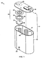
- FIG. 1 shows battery 10 of one embodiment of the invention.
- FIGs. 2A and 2B show a top view and cross-sectional view of battery 10, respectively.
- battery 10 includes first electrode 12 and second electrode 14.
- First electrode 12 is electrically connected to feed-through device 16, which includes first component 18, which is proximal to first electrode 12, and second component 20, which is distal to first electrode 12.
- the electrodes 12, 14 are placed inside battery can 21 that includes cell casing 22 and lid 24, i.e., internal space 27 defined by cell casing 22 and lid 24.
- Cell casing 22 and lid 24 of battery 10 are in electrical communication with each other.
- feed-through includes any material or device that connects electrode 12 of battery 10, within internal space 27 defined by cell casing 22 and lid 24, with a component of the battery external to that defined internal space.
- feed-through device 16 extends through a pass-through hole defined by lid 24.
- Feed-through device 16 also can pass through lid 24 without deformation, such as bending, twisting and/or folding, and can increase cell capacity.
- One benefit of using such a feed-through device includes a potential increase (e.g., 5-15%) in cell capacity due to increased volume utilization, as compared to that of a conventional lithium battery in which current-carrying tabs are folded or bent into a cell casing and are welded with internal electrodes.
- Any other suitable means known in the art can be used in the invention to connect electrode 12 with a component of the battery external to battery can 21, e.g., a terminal of the battery.
- Cell casing 22 and lid 24 can be made of any suitable conductive material which is essentially stable electrically and chemically at a given voltage of batteries, such as the lithium-ion batteries of the invention.
- suitable materials of cell casing 22 include aluminum, nickel, copper, steel, nickel-plated iron, stainless steel and combinations thereof.
- cell casing 22 is of, or includes, aluminum.
- suitable materials of lid 24 are the same as those listed for cell casing 22.
- lid 24 is made of the same material as cell casing 22.
- both cell casing 22 and lid 24 are formed of, or include, aluminum.
- Lid 24 can hermetically seal cell casing 22 by any suitable method known in the art.
- lid 24 and cell casing 22 are welded to each other.
- other forms of electrical connection of lid 24 to cell casing 22 known in the art, such as crimping can be employed in the invention.
- Battery can 21, for example, lid 24, is electrically insulated from feed-through device 16, for example, by an insulating gasket (not shown).
- the insulating gasket is formed of a suitable insulating material, such as polypropylene, polyvinylfluoride (PVF), etc.
- At least one of cell casing 22 and lid 24 of battery can 21 are in electrical communication with second electrode 14 of battery 10 through CID 28.
- Battery can 21, i.e., cell casing 22 and lid 24, is electrically insulated from a first terminal of battery 10, and at least a portion of battery can 21 is at least a component of a second terminal of battery 10, or is electrically connected to the second terminal.
- at least a portion of lid 24 or the bottom of cell casing 22 serves as a second terminal of battery 10
- feed-through device 16 includes top conductive layer 26, which can serve as a first terminal of battery 10 in electrical communication with first electrode 12.
- First component 18, second component 20 and top conductive layer 26 each and independently can be made of any suitable conductive material known in the art, for example, nickel.
- Battery 10 of the invention includes CID 28. Although one CID 28 is employed in battery 10, more than one CID 28 can be employed in the invention.
- CID 28 includes first conductive plate 30 and second conductive plate 32 in electrical communication with each other (e.g., by welding, crimping, riveting, etc.). First conductive plate 30 is in electrical communication with second electrode 14, and second conductive plate 32 is in electrical contact with battery can 21, for example, lid 24.
- second conductive plate 32 separates from ( e.g ., deforms away or is detached from) first conductive plate 30 when gauge pressure inside the battery is greater than a predetermined value, for example, between about 5 kg/cm 2 and about 10 kg/cm 2 , whereby a current flow between second electrode 14 and battery can 21, at least a portion of which is at least a component of a second terminal, or is electrically connected to the second terminal, is interrupted.
- a predetermined value for example, between about 5 kg/cm 2 and about 10 kg/cm 2
- venting means 56 e.g, at cell wall or the bottom part of cell casing 22, or second conductive plate 32
- the predetermined gauge pressure value for activation of venting means 56 is higher than that for activation of CID 28, for example, between about 5 kg/cm 2 and about 10 kg/cm 2 .
- gauge pressure values or sub-ranges suitable for the activation of CID 28 and those for activation of venting means 56 are selected from among the predetermined gauge pressure ranges such that there is no overlap between the selected pressure values or sub-ranges.
- the values or ranges of gauge pressure for the activation of CID 28 and those for the activation of venting means 56 differ by at least about 2 kg/cm 2 pressure difference, more preferably by at least about 4 kg/cm 2 , even more preferably by at least about 6 kg/cm 2 , such as by about 7 kg/cm 2 .
- CID 28 further includes insulator 34 (e.g., insulating layer or insulating gasket) between a portion of first conductive plate 30 and second conductive plate 32.
- CID 28 is in electrical communication with cell casing 22 of the battery.
- the second conductive plate separates from ( e.g ., deforms away or is detached from) the first conductive plate when pressure inside the battery is greater than a predetermined value, for example, an internal gauge pressure in a range of between about 5 kg/cm 2 and about 10 kg/cm 2 , whereby a current flow between the second electrode and the second terminal is interrupted.
- At least one of first conductive plate 30 and insulator 34 of CID 28 includes at least one hole (e.g., holes 36 or 38 in FIG. 1 ) through which gas within battery 10 is in fluid communication with second conductive plate 32.
- CID 28 further includes end plate 40 disposed over second conductive plate 32, and defining at least one hole 42 through which second conductive plate 32 is in fluid communication with the atmosphere outside the battery.
- end plate 40 is a part of battery can 21, as shown in FIX. 1 where end plate 40 is a part of lid 24 of battery can 21.
- end plate 40 is at battery can 21 of battery 14, for example, over, under or at lid 24 of battery can 21, and in electrical communication with battery can 21.
- CID 28 in the invention is placed within battery can 21, or alternatively, a portion of CID 28 is within battery can 21 and another portion of CID. 28 is at or above battery can 21.
- CID 28 can be electrically connected to lid 24 by any suitable means, such as welding, crimping, etc.
- at least one component of CID 28, first and second conductive plates, 30, 32, insulator 34 and end pate 40 are positioned within battery can 21.
- at least one component of CID 28, e.g., first and second conductive plates, 30, 32, insulator 34, and end plate 40 is seated within at recess at battery can 21, e.g., lid 24.
- At least one of first and second conductive prates. 30, 32, and end plate 40 is a component of battery can 21, e.g., lid 24, or side or bottom of cell casing 22.
- at least one of first and second conductive plates, 30, 32, and end plate 40 is a portion of battery can 21, e,g., lid 24, or side or bottom of cell casing 22.
- at least one of first and second conductive plates, 30, 32, and end plate 40 is coined or stamped at lid 24, or the side or the bottom of cell casing 22, preferably, at lid 24.
- end plate 40 is a part of lid 24 (e.g., coined or stamped), and first and second conductive plates, 30, 32, are placed within cell casing 22, as shown in FIG. 1 .
- First conductive plate 30 and second conductive plate 32 are made of aluminium.
- battery can 21 e.g., cell casing 22 and lid 24
- first conductive plate 30 and second conductive plate 32 are all made of aluminium.
- Cell casing 22 (e.g., the cell wall or the bottom part) includes at least one venting means 56 as a means for venting interior space 27 when necessary, such as when gauge pressure within lithium ion battery 10 is greater than a value of between about 10 kg/cm 2 and about 20 kg/cm 2 .
- second conductive plate 32 includes at least one venting means 56 (not shown). It is to be understood that any suitable type of venting means can be employed as long as the means provide hermetic sealing in normal battery operation conditions. Various suitable examples of venting meons are described. In U.S. Provisional Application No. 60/717,898, filed on September 16, 2005 .
- venting means 56 include vent scores.
- the term "score” means partial incision of section(s) of a cell casing, such as cell casing 22, that is designed to allow the cell pressure and any internal cell components to be released at a defined internal gauge pressure, (e.g., between about 10 and about 20 kg/cm 2 ).
- the vent score is directionally positioned away from a user/or neighboring cells.
- more than one vent score can be employed.
- pattern vent scores can be employed.
- the vent score can be parallel, perpendicular, diagonal to a major stretching (or drawing) direction of the cell casing material during creation of the shape of cell casing 22. Consideration is also given to vent score properties, such as depth, shape and length (size).
- the batteries of the invention can further include a positive thermal coefficient layer (PTC) in electrical communication with either the first terminal or the second terminal, preferably in electrical communication with the first terminal.
- PTC positive thermal coefficient layer
- Suitable PTC materials are those known in the art. Generally, suitable PTC materials are those that, when exposed to an electrical current in excess of a design threshold, its electrical conductivity decreases with increasing temperature by several orders of magnitude (e.g., 10 4 to 10 6 or more). Once the electrical current is reduced below a suitable threshold, in general, the PTC material substantially returns to the initial electrical resistivity.
- the PTC material includes small quantities of semiconductor material in a polycrystalline ceramic, or a slice of plastic or polymer with carbon grains embedded in it.
- the semiconductor material or the plastic or polymer with embedded carbon grains forms a barrier to the flow of electricity and causes electrical resistance to increase precipitously.
- the temperature at which electrical resistivity precipitously increases can be varied by adjusting the composition of the PTC material, as is known in the art.
- An "operating temperature" of the PTC material is a temperature at which the PTC exhibits an electrical resistivity about half way between its highest and lowest electrical resistance.
- the operating temperature of the PTC layer employed in the invention is between about 70° Celsius and about 150° Celsius.
- Examples of specific PTC materials include polycrystalline ceramics containing small quantities of barium titanate (BaTiO 3 ), and polyolefins including carbon grains embedded therein.
- Examples of commercially available PTC laminates that include a PTC layer sandwiched between two conducting metal layers include LTP and LR4 series manufactured by Raychem Co. Generally, the PTC layer has a thickness in a range of about 50 ⁇ m and about 300 ⁇ m.
- the PTC layer includes electrically conductive surface, the total area of which is at least about 25% or at least about 50% (e.g., about 48% or about 56%) of the total surface area of lid 24 or the bottom of battery 10.
- the total surface area of the electrically conductive surface of the PTC layer can be at least about 56% of the total surface area of lid 24 or the bottom of battery 10. Up to 100% of the total surface area of lid 24 of battery 10 can occupied by the electrically conductive surface of the PTC layer. Alternatively, the whole, or part, of the bottom of battery 10 can be occupied by the electrically conductive surface of the PTC layer.
- the PTC layer can be positioned internally or externally to the cell can (e.g., lid 24 or the bottom part of cell casing 22), preferably externally to the cell can, for example, over lid 24 of the cell can.
- the PTC layer is between a first conductive layer and a second conductive layer and at least a portion of the second conductive layer is at least a component of the first terminal, or is electrically connected to the first terminal.
- the first conductive layer is connected to the feed-through device. Suitable examples of such a PTC layer sandwiched between the first and second conductive layers are described in U.S. Patent Application No. 11/474,081, filed on June 23, 2006 .
- the cells of batteries of the invention are rechargeable, such as rechargeable lithium-ion cells or batteries.
- the cells or batteries of the invention can be in any suitable shape, e.g., cylindrical or prismatic.
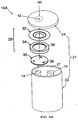
- the cells of batteries of the invention are cylindrical (e.g., 26650, 18650, or 14500 configuration), as shown in FIGs. 4A and 4B.
- FIG. 4B shows the bottom part of cell casing 22 of battery 10A of FIG. 4A .
- conductive layer 26 at feed-through device 16 which is in electrical communication with first electrode 12, is placed at the bottom part of cell casing 22, as shown in FIG. 4B .
- Conductive layer 26 can serve as a first terminal of battery 10A.
- at least one venting means 56 is placed at the bottom part of cell casing 22 (see FIG. 4B ).
- venting means 56 can be placed at second conductive plate 32 (not shown).
- the cells or batteries of the invention are prismatic, as shown in FIG. 1 (stacked or wound, e.g., 183665 or 103450 configuration).
- the cells or batteries of the invention are of a prismatic shape that is oblong.
- the present invention can use all types of prismatic cell casings, an oblong cell casing is preferred partly due to the two features described below.
- an oblong shape such as the 183665 form factor
- the available internal volume of an oblong shape is larger than the volume of two 18650 cells, when comparing stacks of the same external volume.
- the oblong cell When assembled into a battery pack, the oblong cell fully utilizes more of the space that is occupied by the battery pack.
- This enables novel design changes to the internal cell components that can increase key performance features without sacrificing cell capacity relative to that found in the industry today.
- Due to the larger available volume one can elect to use thinner electrodes, which have relatively higher cycle life and a higher rate capability.
- an oblong can has larger flexibility. For instance, an oblong shape can flex more at the waist point compared to a cylindrically shaped can, which allows less flexibility as stack pressure is increasing upon charging. The increased flexibility decreases mechanical fatigue on the electrodes, which, in turn, causes higher cycle life. Also, clogging of pores of a separator in batteries can be improved by the relatively lower stack pressure.
- the oblong shape provides a snug fit to the jelly roll, which minimizes the amount of electrolyte necessary for the battery.
- the relatively lower amount of electrolyte results in less available reactive material during a misuse scenario and hence higher safety.
- cost is lower due to a lower amount of electrolyte.
- a prismatic can with a stacked electrode structure, whose cross-section is in a rectangular shape full volume utilization is possible without unnecessary electrolyte, but this type of can design is more difficult and hence more costly from a manufacturing point-of-view.
- a plurality of lithium-ion batteries of the invention can be connected in a battery pack, wherein each of the batteries (cells) is connected with each other in series, parallel, or in series and parallel. In some battery packs of the invention, there are no parallel connections between the batteries.
- At least one cell has a prismatic shaped cell casing, and more preferably, an oblong shaped cell casing, as shown in FIG. 1 . More preferably, at least one cell has an 183665 configuration.
- the capacity of the cells in the battery pack is typically equal to or greater than about 3.0 Ah, more preferably equal to or greater than about 4.0 Ah.
- the internal impedance of the cells is preferably less than about 50 milliohms, and more preferably less than 30 milliohms.
- the lithium-ion batteries and battery packs of the invention can be used for portable power devices, such as portable computers, power tools, toys, portable phones, camcorders, PDAs and the like.
- portable electronic devices such as portable computers, power tools, toys, portable phones, camcorders, PDAs and the like.
- their charges are, in general, designed for a 4.20 V charging voltage.
- the lithium-ion batteries and battery packs of the invention are particularly useful for these portable electronic devices.
- the present invention also includes methods of producing a battery, such as a lithium-ion battery, as described above.
- the methods include forming a cell casing as described above, and disposing a first electrode and a second electrode within the cell casing.
- a current interrupt device, as described above e.g., current interrupt device 28
- Positive and negative electrodes and electrolytes for the lithium-ion batteries of the invention can be formed by suitable methods known in the art.
- suitable negative-active materials for the negative electrodes include any material allowing lithium to be doped or undoped in or from the material.
- suitable negative-active materials include carbonaceous materials, for example, non-graphitic carbon, artificial carbon, artificial graphite, natural graphite, pyrolytic carbons, cokes such as pitch coke, needle coke, petroleum coke, graphite, vitreous carbons, or a heat-treated organic polymer compounds obtained by carbonizing phenol resins, furan resins, or similar, carbon fibers, and activated carbon.
- metallic lithium, lithium alloys, and an alloy or compound thereof are usable as the negative active materials.
- the metal element or semiconductor element allowed to form an alloy or compound with lithium may be a group IV metal element or semiconductor element, such as but not limited to, silicon or tin.
- amorphous tin that is doped with a transition metal such as cobalt or iron/nickel, is a metal that is suitable as an anode material in these types of batteries.
- Oxides allowing lithium to be doped or undoped in or out from the oxide at a relatively basic potential, such as iron oxide, ruthenium oxide, molybdenum oxide, tungsten oxide, titanium oxide, and tin oxide, and nitrides, similarly, are usable as the negative-active materials.
- Suitable positive-active materials for the positive electrodes include any material known in the art, for example, lithium nickelate (e.g ., Li 1+x NiM'O 2 ), lithium cobaltate (e.g ., Li i+x CoO 2 ), olivine-type compounds (e.g ., Li 1+x FePO 4 ), manganate spinel (e.g ., Li 1+x9 Mn 2-y9 O 4 (x9 and y9 are each independently equal to or greater than zero and equal to or less than 0.3) or Li 1+x1 (Mn 1-y1 A' y2 ) 2-x2 O z1 ) (x1 and x2 are each independently equal to or greater than 0.01 and equal to or less than 0.3; y1 and y2 are each independently equal to or greater than 0.0 and equal to or less than 0.3; z1 is equal to or greater than 3.9 and equal to or less than 4.1), and mixtures thereof.
- lithium nickelate e.g ., Li 1
- the positive-active materials for the positive electrodes of the invention include a lithium cobaltate, such as Li (1+x8) CoO z8 . More specifically, a mixture of about 60-90 wt% (e.g. about 80 wt%) of a lithium cobaltate, such as Li (1+x8) CoO z8 , and about 40-10 wt% (e.g., about 20 wt%) of a manganate spinel (e.g., having about 100-115 mAh/g), such as Li (1+x1) Mn 2 O z1 , preferably Li (1+x1) Mn 2 O 4, is employed for the invention.
- a lithium cobaltate such as Li (1+x8) CoO z8
- the value x I is equal to or greater than zero and equal to or less than 0.3 (e.g., 0.05 ⁇ x1 ⁇ 0.15).
- the value z1 is equal to or greater than 3.9 and equal to or greater than 4.2.
- the value x8 is equal to or greater than zero and equal to or less than 0.2.
- the value z8 is equal to or greater than 1.9 and equal to or greater than 2.1.
- the positive-active materials for the invention include a mixture that includes a lithium cobaltate, such as Li (1+x8) CoO z8 , and a manganate spinel represented by an empirical formula of Li (1+x1) (Mn 1-y1 A' y2 ) 2 . x2 O z1 .
- the values x1 and x2 are each independently equal to or greater than 0.01 and equal to or less than 0.3.
- the values y1 and y2 are each independently equal to or greater than 0.0 and equal to or less than 0.3.
- the value z1 is equal to or greater than 3.9 and equal to or less than 4.2.
- A' is at least one member of the group consisting of magnesium, aluminum, cobalt, nickel and chromium. More specifically, the lithium cobaltate and the manganate spinel are in a weight ratio of lithium cobaltate: manganate spinel between about 0.95:0.05 and about 0.9:0.1 to about 0.6:0.4.
- the positive-active materials for the invention include a mixture that includes 100% of a lithium cobaltate, such as Li (1+x8) CoO z8 .
- the positive-active materials for the invention include at least one lithium oxide selected from the group consisting of: a) a lithium cobaltate; b) a lithium nickelate; c) a manganate spinel represented by an empirical formula of Li (1+x1) (Mn 1-y1 A' y2 ) 2-x2 O z1 ; d) a manganate spinel represented by an empirical formula of Li( 1+x1 )Mn 2 O z1 or Li 1+x9 M n2-y9 O 4 ; and e) an olivine compound represented by an empirical formula of Li( 1-x10 )A" x10 MPO 4 .
- the values of x1, z1, x9 and y9 are as described above.
- the value, x2 is equal to or greater than 0.01 and equal to or less than 0.3.
- the values of y1 and y2 are each independently equal to or greater than 0.0 and equal to or less than 0.3.
- A' is at least one member of the group consisting of magnesium, aluminum, cobalt, nickel and chromium.
- the value, x10 is equal to or greater than 0.05 and equal to or less than 0.2, or the value, x 10, is equal to or greater than 0.0 and equal to or less than 0.1.
- M is at least one member of the group consisting of iron, manganese, cobalt and magnesium.
- A" is at least one member of the group consisting of sodium, magnesium, calcium, potassium, nickel and niobium.
- a lithium nickelate that can be used in the invention includes at least one modifier of either the Li atom or Ni atom, or both.
- a "modifier” means a substituent atom that occupies a site of the Li atom or Ni atom, or both, in a crystal structure of LiNiO 2 .
- the lithium nickelate includes only a modifier of, or substituent for, Li atoms ("Li modifier”).
- the lithium nickelate includes only a modifier of, or substituent for, Ni atoms ("Ni modifier”).
- the lithium nickelate includes both the Li and Ni modifiers. Examples of Li modifiers include barium (Ba), magnesium (Mg), calcium (Ca) and strontium (Sr).
- Ni modifiers include those modifiers for Li and, in addition, aluminium (Al), manganese (Mn) and boron (B).
- Other examples of Ni modifiers include cobalt (Co) and titanium (Ti).
- the lithium nickelate is coated with LiCoO 2 .
- the coating can be, for example, a gradient coating or a spot-wise coating.
- Li x3 Ni 1-z3 M' z3 O 2 where 0.05 ⁇ x3 ⁇ 1.2 and 0 ⁇ z3 ⁇ 0.5
- M' is one or more elements selected from a group consisting of Co, Mn, Al, B, Ti, Mg, Ca and Sr.
- M' is one or more elements selected from a group consisting of Mn, Al, B, Ti, Mg, Ca and Sr.
- Li x4 A' x5 Ni (1-y4-z4) Co y4 Q z4 O 2 is represented by an empirical formula of Li x4 A' x5 Ni (1-y4-z4) Co y4 Q z4 O 2 where x4 is equal to or greater than about 0.1 and equal to or less than about 1.3; x5 is equal to or greater than 0.0 and equal to or less than about 0.2; y4 is equal to or greater than 0.0 and equal to or less than about 0.2; z4 is equal to or greater than 0.0 and equal to or less than about 0.2; a is greater than about 1.5 and less than about 2.1; A* is at least one member of the group consisting of barium (Ba), magnesium (Mg) and calcium (Ca); and Q is at least one member of the group consisting of aluminum (Al), manganese (Mn) and boron (B).
- y4 is greater than zero.
- x5 is equal to zero, and z4 is greater than 0.0 and equal to or less than about 0.2.
- z4 is equal to zero, and x5 is greater than 0.0 and equal to or less than about 0.2.
- x5 and z4 are each independently greater than 0.0 and equal to or less than about 0.2.
- x5, y4 and z4 are each independently greater than 0.0 and equal to or less than about 0.2.
- Various examples of lithium nickelates where x5, y4 and z4 are each independently greater than 0.0 and equal to or less than about 0.2 can be found in U.S. Patent Nos. 6,855,461 and 6,921,609 .
- a specific example of the lithium nickelate is LiNi 0.8 Co 0.15 Al 0.05 O 2 .
- a preferred specific example is LiCoO 2 -coated LiNi 0.8 Co 0.15 Al 0.05 O 2 .
- LiCoO 2 doe not fully coat the nickelate core particle.
- the composition of LiNi 0.8 Co 0.15 Al 0.05 O 2 coated with LiCoO 2 can naturally deviate slightly in composition from the 0.8:0.15:0.05 weight ratio between Ni:Co:Al. The deviation can range about 10-15% for the Ni, 5-10% for Co and 2-4% for Al.
- Another specific example of the lithium nickelate is Li 0.97 Mg 0.03 Ni 0.9 Co 0.1 O 2 .
- a preferred specific example is LiCoO 2 -coatted Li 0.97 Mg 0.03 Ni 0.9 Co 0.1 O 2 .
- the composition of Li 0.97 Mg 0.03 Ni 0.9 Co 0.1 O 2 coated with LiCoO 2 can deviate slightly in composition from the 0.03:0.9:0.1 weight ratio between Mg:Ni:Co. The deviation can range about 2-4% for Mg, 10-15% for Ni and 5-10% for Co.
- Another preferred nickelate that can be used in the present invention is Li(Ni 1/3 Co 1/3 M 1/3 )O 2 , also called "333-type nickelate.” This 333-type nickelate optionally can be coated with LiCoO 2. as described above.
- lithium cobaltates that can be used in the invention include Li 1+x8 CoO 2 that is modified by at least one of Li or Co atoms.
- Li modifiers are as described above for Li of lithium nickelates.
- Co modifiers include the modifiers for Li and aluminum (Al), manganese (Mn) and boron (B).
- Ni nickel
- Ti titanium
- lithium cobaltates represented by an empirical formula of Li x6 M' (1-y6) Co (1-z6) M" z6 O 2 , where x6 is greater than 0.05 and less than 1.2; y6 is equal to or greater than 0 and less than 0.1, z6 is equal to or greater than 0 and less than 0.5; M' is at least one member of magnesium (Mg) and sodium (Na) and M" is at least one member of the group consisting of manganese (Mn), aluminum (Al), boron (B), titanium (Ti), magnesium (Mg), calcium (Ca) and strontium (Sr), can be used in the invention.
- Mn manganese
- Al aluminum
- B boron
- Ti titanium
- Mg magnesium
- Ca calcium
- lithium cobaltate that can be used in the invention is unmodified Li 1+x8 CoO 2 , such as LiCoO 2 .
- the lithium cobaltate e.g., LiCoO 2
- the lithium cobaltate doped with Mg and/or coated with a refractive oxide or phosphate, such as ZrO 2 or Al(PO 4 ).
- lithium oxide compounds employed have a spherical-like morphology, since it is believed that this improves packing and other production-related characteristics.
- a crystal structure of each of the lithium cobaltate and lithium nickelate is independently a R-3m type space group (rhombohedral, including distorted rhombohedral).
- a crystal structure of the lithium nickelate can be in a monoclinic space group (e.g., P2/m or C2/m).
- olivine compounds that are suitable for use in the invention are generally represented by a general formula Li 1-x2 A" x2 MPO 4 , where x2 is equal to or greater than 0.05, or x2 is equal to or greater than 0.0 and equal to or greater than 0.1; M is one or more elements selected from a group consisting of Fe, Mn, Co, or Mg; and A" is selected from a group consisting of Na, Mg, Ca, K, Ni, Nb.
- M is Fe or Mn. More preferably, LiFePO 4 or LiMnPO 4. or both are used in the invention.
- the olivine compounds are coated with a material having relatively high electrical conductivity, such as carbon.
- carbon-coated LiFePO 4 or carbon-coated LiMnPO 4 is employed in the invention.
- olivine compounds where M is Fe or Mn can be found in U.S. Patent No. 5,910,382 .
- the olivine compounds typically have a small change in crystal structure upon charging/discharging, which generally makes the olivine compounds superior in terms of cycle characteristics. Also, safety is generally high, even when a battery is exposed to a high temperature environment.
- Another advantage of olivine compounds e.g., LiFePO 4 and LiMnPO 4 ) is their relatively low cost.
- Manganate spinel compounds have a manganese base, such as LiMn 2 O 4 . While the manganate spinel compounds typically have relatively low specific capacity (e.g., in a range of about 110 to 115 mAh/g), they have relatively high power delivery when formulated into electrodes and typically are safe in terms of chemical reactivity at higher temperatures. Another advantage of the manganate spinel compounds is their relatively low cost.
- One type of manganate spinel compounds that can be used in the invention is represented by an empirical formula of Li( 1+x1) (Mn 1-y1 A' y2 ) 2-x2 O z1 , where A' is one or more of Mg, Al, Co, Ni and Cr; x1 and x2 are each independently equal to or greater than 0.01 and equal to or less than 0.3; y1 and y2 are each independently equal to or greater than 0.0 and equal to or less than 0.3; z1 is equal to or greater than 3.9 and equal to or less than 4.1.
- A' includes a M 3+ ion, such as Al 3+ , Co 3+ , Ni 3+ and Cr 3+ , more preferably Al 3+ .
- the manganate spinel compounds of Li (1+x1) (Mn 1-y1 A' y2 ) 2-x2 O z1 can have enhanced cyclability and power compared to those of LiMn 2 O 4 .
- Another type of manganate spinel compounds that can be used in the invention is represented by an empirical formula of Li (1+x1) Mn 2 O z1 , where x1 and z1 are each independently the same as described above.
- the manganate spinel for the invention includes a compound represented by an empirical formula of Li 1+x9 Mn 2-y9 O z9 where x9 and y9 are each independently equal to or greater than 0.0 and equal to or less than 0.3 (e.g., 0.05 ⁇ x9, y9 ⁇ 0.15); and z9 is equal to or greater than 3.9 and equal to or less than 4.2.
- Specific examples of the manganate spinel that can be used in the invention include LiMn 1.9 Al 0 . 1 O 4 , Li 1+x1 Mn 2 O 4 , Li 1+x7 Mn 2-y7 O 4 , and their variations with Al and Mg modifiers.
- cathode materials described herein are characterized by empirical formulas that exist upon manufacture of lithium-ion batteries in which they are incorporated. It is understood that their specific compositions thereafter are subject to variation pursuant to their electrochemical reactions that occur during use (e.g., charging and discharging).
- non-aqueous electrolytes examples include a non-aqueous electrolytic solution prepared by dissolving an electrolyte salt in a non-aqueous solvent, a solid electrolyte (inorganic electrolyte or polymer electrolyte containing an electrolyte salt), and a solid or gel-like electrolyte prepared by mixing or dissolving an electrolyte in a polymer compound or the like.
- the non-aqueous electrolytic solution is typically prepared by dissolving a salt in an organic solvent.
- the organic solvent can include any suitable type that has been generally used for batteries of this type. Examples of such organic solvents include propylene carbonate (PC), ethylene carbonate (EC), diethyl carbonate (DEC), dimethyl carbonate (DMC), 1,2-dimethoxyethane, 1,2-diethoxyethane, ⁇ -butyrolactone, tetrahydrofuran, 2-methyl tetrahydrofuran, 1,3-dioxolane, 4-methyl-1,3-dioxolane, diethyl ether, sulfolane, methylsulfolane, acetonitrile, propionitrile, anisole, acetate, butyrate, propionate and the like. It is preferred to use cyclic carbonates such as propylene carbonate, or chain carbonates such as dimethyl carbonate and diethyl carbonate. These organic solvents can be used singly or
- Additives or stabilizers may also be present in the electrolyte, such as VC (vinyl carbonate), VEC (vinyl ethylene carbonate), EA (ethylene acetate), TPP (triphenylphosphate), phosphazenes, biphenyl (BP), cyclohexylbenzene (CHB), 2,2-diphenylpropane (DP), lithium bis(oxalato)borate (LiBoB), ethylene sulfate (ES) and propylene sulfate.
- VC vinyl carbonate
- VEC vinyl ethylene carbonate
- EA ethylene acetate
- TPP triphenylphosphate
- DP cyclohexylbenzene
- DP 2,2-diphenylpropane
- LiBoB lithium bis(oxalato)borate
- ES ethylene sulfate
- propylene sulfate propylene sulfate
- the solid electrolyte can include an inorganic electrolyte, a polymer electrolyte and the like insofar as the material has lithium-ion conductivity.
- the inorganic electrolyte can include, for example, lithium nitride, lithium iodide and the like.
- the polymer electrolyte is composed of an electrolyte salt and a polymer compound in which the electrolyte salt is dissolved.
- the polymer compounds used for the polymer electrolyte include ether-based polymers such as polyethylene oxide and cross-linked polyethylene oxide, polymethacrylate ester-based polymers, acrylate-based polymers and the like. These polymers may be used singly, or in the form of a mixture or a copolymer of two kinds or more.
- a matrix of the gel electrolyte may be any polymer insofar as the polymer is gelated by absorbing the above-described non-aqueous electrolytic solution.
- the polymers used for the gel electrolyte include fluorocarbon polymers such as polyvinylidene fluoride (PVDF), polyvinylidene-co-hexafluoropropylene (PVDF-HFP) and the like.
- Examples of the polymers used for the gel electrolyte also include polyacrylonitrile and a copolymer of polyacrylonitrile.
- Examples of monomers (vinyl based monomers) used for copolymerization include vinyl acetate, methyl methacrylate, butyl methacylate, methyl acrylate, butyl acrylate, itaconic acid, hydrogenated methyl acrylate, hydrogenated ethyl acrylate, acrlyamide, vinyl chloride, vinylidene fluoride, and vinylidene chloride.
- polymers used for the gel electrolyte further include acrylonitrile-butadiene copolymer rubber, acrylonitrile-butadiene- -styrene copolymer resin, acrylonitrile-chlorinated polyethylene-propylenediene-styrene copolymer resin, acrylonitrile-vinyl chloride copolymer resin, acrylonitrile-methacylate resin, and acrlylonitrile-acrylate copolymer resin.
- acrylonitrile-butadiene copolymer rubber acrylonitrile-butadiene- -styrene copolymer resin
- acrylonitrile-chlorinated polyethylene-propylenediene-styrene copolymer resin acrylonitrile-vinyl chloride copolymer resin
- acrylonitrile-methacylate resin acrylonitrile-methacylate resin
- polymers used for the gel electrolyte include ether based polymers such as polyethylene oxide, copolymer of polyethylene oxide, and cross-linked polyethylene oxide.
- monomers used for copolymerization include polypropylene oxide, methyl methacrylate, butyl methacylate, methyl acrylate, butyl acrylate.
- a fluorocarbon polymer is preferably used for the matrix of the gel electrolyte.
- the electrolyte salt used in the electrolyte may be any electrolyte salt suitable for batteries of this type.
- the electrolyte salts include LiClO 4 , LiAsF 6 , LiPF 6 , LiBF 4 , LiB(C 6 H 5 ) 4 , LiB(C 2 O 4 ) 2 , CH 3 SO 3 Li, CF 3 SO 3 Li, LiCl, LiBr and the like.
- a separator separates the positive electrode from the negative electrode of the batteries.
- the separator can include any film-like material having been generally used for forming separators of non-aqueous electrolyte secondary batteries of this type, for example, a microporous polymer film made from polypropylene, polyethylene, or a layered combination of the two.
- a microporous separator made of glass fiber or cellulose material can in certain cases also be used. Separator thickness is typically between 9 and 25 ⁇ m.
- a positive electrode can be produced by mixing the cathode powders at a specific ratio. 90 wt % of this blend is then mixed together with 5 wt % of acetylene black as a conductive agent, and 5 wt % of PVDF as a binder. The mix is dispersed in N-methyl-2-pyrrolidone (NMP) as a solvent, in order to prepare slurry. This slurry is then applied to both surfaces of an aluminum current collector foil, having a typical thickness of about 20um, and dried at about 100-150° C. The dried electrode is then calendared by a roll press, to obtain a compressed positive electrode.
- NMP N-methyl-2-pyrrolidone
- a negative electrode can be prepared by mixing 93 Wt% of graphite as a negative active material, 3 wt% acetylene black, and 4 wt% of PVDF as a binder. The negative mix was also dispersed in N-methyl-2-pyrrolidone as a solvent, in order to prepare the slurry. The negative mix slurry was uniformly applied on both surfaces of a strip-like copper negative current collector foil, having a typical thickness of about 10 um. The dried electrode is then calendared by a roll press to obtain a dense negative electrode.
- the negative and positive electrodes and a separator formed of a polyethylene film with micro pores, of thickness 25 um, are generally laminated and spirally wound to produce a spiral type electrode element.
- one or more positive lead strips are attached to the positive current electrode, and then electrically connected to the positive terminal of the batteries of the invention.
- a negative lead made of, e.g., nickel metal, connects the negative electrode, and then attached to a feed-through device, such as feed-through device 16.
- An electrolyte of for instance EC:DMC:DEC with 1M LiPF 6 is vacuum filled in the cell casing of a lithium-ion battery of the invention, where the cell casing has the spirally wound "jelly roll.”
Claims (22)
- Pile (10), comprenant :a) une première borne (26) en communication électrique avec une première électrode (12) de la pile ;b) une seconde borne (40) en communication électrique avec une seconde électrode (14) de la pile ;c) un boîtier de pile (21) qui contient de l'aluminium et qui est isolé électriquement de la première borne, au moins une partie du boîtier de pile pouvant constituer au moins un composant de la seconde borne, ou étant reliée électriquement à la seconde borne, la pile pouvant inclure un bac d'élément (22) et un couvercle (24) communiquant électriquement l'un avec l'autre ; etd) au moins un dispositif d'interruption de courant (28) en communication électrique avec le boîtier de pile, le dispositif d'interruption de courant incluant,caractérisée en ce que la première borne est une borne négative, en ce que la seconde borne est une borne positive et en ce que chacune des première et seconde plaques conductrices du dispositif d'interruption de courant contient de l'aluminium.i) une première plaque conductrice (30) en communication électrique avec la seconde électrode ; etii) une seconde plaque conductrice (32) en communication électrique avec la première plaque conductrice, la seconde plaque conductrice se séparant de la première plaque conductrice quand la pression à l'intérieur de la pile est supérieure à une valeur prédéterminée, interrompant ainsi le passage de courant entre la seconde électrode et la seconde borne,
- Pile selon la revendication 1, dans laquelle la seconde plaque conductrice est en communication fluide avec l'atmosphère extérieure à la pile.
- Pile selon la revendication 1, dans laquelle au moins une partie du dispositif d'interruption de courant est constituée par un composant du boîtier de pile.
- Pile selon la revendication 1, dans laquelle au moins une partie du dispositif d'interruption de courant est une partie du boîtier de pile.
- Pile selon la revendication 1, dans laquelle au moins une partie du dispositif d'interruption de courant est matricé ou forgé sur le boîtier de pile.
- Pile selon la revendication 1, dans laquelle la première borne est située au niveau du couvercle du boîtier de pile ou au fond du bac d'élément.
- Pile selon la revendication 1, dans laquelle la première et/ou la seconde plaque conductrice présente(nt) au moins un élément en saillie au niveau duquel la première et la seconde plaque conductrice sont en communication électrique l'une avec l'autre.
- Pile selon la revendication 1, dans laquelle le dispositif d'interruption de courant inclut en outre un isolant entre une partie de la première plaque conductrice et une partie de la seconde plaque conductrice.
- Pile selon la revendication 1, dans laquelle la première plaque conductrice et/ou l'isolant inclut(ent) au moins un trou par le biais duquel le gaz contenu dans la pile est en communication fluide avec la seconde plaque conductrice.
- Pile selon la revendication 1, dans laquelle la première et la seconde plaque conductrice sont reliées entre elles par au moins une connexion établie par soudage ou refoulement.
- Pile selon la revendication 1, dans laquelle le bac d'élément inclut au moins un évent (56) à travers lequel le gaz contenu dans l'élément peut être évacué lorsque la pression à l'intérieur de la pile est supérieure à une valeur prédéterminée.
- Pile selon la revendication 1, dans laquelle le bac d'élément du boîtier de pile peut avoir une section transversale de forme prismatique.
- Pile selon la revendication 1, incluant en outre une couche de coefficient thermique positif en communication électrique avec la première borne ou la seconde borne.
- Bloc d'éléments comprenant une pluralité d'éléments, chacun desdits éléments étant une pile selon la revendication 1 ou 12.
- Bloc d'éléments selon la revendication 14, dans lequel les éléments sont montés en série, aucun élément n'étant connecté en parallèle.
- Procédé de production d'une pile, comprenant les étapes consistant à :a) disposer une première électrode et une seconde électrode à l'intérieur d'un boîtier de pile comprenant un bac d'élément et un couvercle qui sont en communication électrique l'un avec l'autre, le boîtier de pile contenant de l'aluminium et étant en communication électrique avec la seconde électrode ;b) former une première borne en communication électrique avec la première électrode, et isolée électriquement du boîtier de pile ;c) former une seconde borne, au moins une partie du boîtier de pile constituant un composant de la seconde borne, ou étant reliée électriquement à la seconde borne; etd) former un dispositif d'interruption de courant en communication électrique avec le boîtier de pile, le dispositif d'interruption de courant incluant :caractérisé en ce que la première borne est une borne négative, en ce que la seconde borne est une borne positive et en ce que chacune des première et seconde plaques conductrices du dispositif d'interruption de courant contient de l'aluminium.i) une première plaque conductrice en communication électrique avec la seconde électrode ; etii) une seconde plaque conductrice en communication électrique avec la première plaque conductrice, la seconde plaque conductrice se séparant de la première plaque conductrice quand la pression à l'intérieur de la pile est supérieure à une valeur prédéterminée, interrompant ainsi le passage de courant entre la seconde électrode et la seconde borne,
- Procédé selon la revendication 16, dans lequel le dispositif d'interruption de courant inclut un isolant entre une partie de la première plaque conductrice et une partie de la seconde plaque conductrice.
- Procédé selon la revendication 16, dans lequel le dispositif d'interruption de courant inclut également une plaque terminale définissant au moins un trou, le couvercle conducteur étant en communication électrique avec la seconde plaque conductrice.
- Procédé selon la revendication 16, dans lequel la première borne est formée au niveau du couvercle du boîtier de pile ou au fond du bac d'élément du boîtier de pile.
- Procédé selon la revendication 16, dans lequel le dispositif d'interruption de courant est formé au niveau du couvercle du boîtier de pile.
- Procédé selon la revendication 16, dans lequel la seconde plaque conductrice est en communication avec l'atmosphère extérieure à la pile.
- Procédé selon la revendication 16, incluant également l'étape consistant à disposer une couche à coefficient thermique positif au-dessus de la pile, ladite couche à coefficient thermique positif étant en communication électrique avec la première borne ou la seconde borne.
Applications Claiming Priority (2)
| Application Number | Priority Date | Filing Date | Title |
|---|---|---|---|
| US81677506P | 2006-06-27 | 2006-06-27 | |
| PCT/US2007/014592 WO2008002487A2 (fr) | 2006-06-27 | 2007-06-22 | Dispositif à interrupteur de courant intégré pour éléments lithium-ion |
Publications (2)
| Publication Number | Publication Date |
|---|---|
| EP2038944A2 EP2038944A2 (fr) | 2009-03-25 |
| EP2038944B1 true EP2038944B1 (fr) | 2011-11-30 |
Family
ID=38779626
Family Applications (1)
| Application Number | Title | Priority Date | Filing Date |
|---|---|---|---|
| EP07835857A Not-in-force EP2038944B1 (fr) | 2006-06-27 | 2007-06-22 | Dispositif à interrupteur de courant intégré pour éléments lithium-ion |
Country Status (9)
| Country | Link |
|---|---|
| US (1) | US8071233B2 (fr) |
| EP (1) | EP2038944B1 (fr) |
| JP (1) | JP2009543293A (fr) |
| KR (1) | KR101295037B1 (fr) |
| CN (1) | CN101479865A (fr) |
| AT (1) | ATE535951T1 (fr) |
| ES (1) | ES2378263T3 (fr) |
| TW (1) | TW200810200A (fr) |
| WO (1) | WO2008002487A2 (fr) |
Cited By (1)
| Publication number | Priority date | Publication date | Assignee | Title |
|---|---|---|---|---|
| US8679670B2 (en) | 2007-06-22 | 2014-03-25 | Boston-Power, Inc. | CID retention device for Li-ion cell |
Families Citing this family (43)
| Publication number | Priority date | Publication date | Assignee | Title |
|---|---|---|---|---|
| WO2007011661A1 (fr) | 2005-07-14 | 2007-01-25 | Boston-Power, Inc. | Electronique de commande pour piles ion-lithium |
| KR100662752B1 (ko) | 2005-10-04 | 2007-01-02 | 엘에스산전 주식회사 | 다극 배선용 차단기 |
| US8131145B2 (en) * | 2006-02-09 | 2012-03-06 | Karl Frederick Scheucher | Lightweight cordless security camera |
| US8026698B2 (en) | 2006-02-09 | 2011-09-27 | Scheucher Karl F | Scalable intelligent power supply system and method |
| US7990102B2 (en) * | 2006-02-09 | 2011-08-02 | Karl Frederick Scheucher | Cordless power supply |
| CN101479865A (zh) | 2006-06-27 | 2009-07-08 | 波士顿电力公司 | 用于锂离子电池的整合性电流中断装置 |
| TWI426678B (zh) | 2006-06-28 | 2014-02-11 | Boston Power Inc | 具有多重充電率之電子裝置、電池組、充電於電子裝置中的鋰離子電荷儲存電源供應器之方法及可攜式電腦 |
| USD632649S1 (en) | 2006-09-29 | 2011-02-15 | Karl F. Scheucher | Cordless power supply |
| US8084154B2 (en) * | 2007-02-08 | 2011-12-27 | Karl Frederick Scheucher | Battery pack safety and thermal management apparatus and method |
| US20090291330A1 (en) * | 2008-04-24 | 2009-11-26 | Boston-Power, Inc. | Battery with enhanced safety |
| FR2933240B1 (fr) * | 2008-06-25 | 2010-10-22 | Commissariat Energie Atomique | Electrolyte non-aqueux pour accumulateur au lithium a tension elevee |
| EP2380226B1 (fr) * | 2008-12-19 | 2016-03-09 | Boston-Power, Inc. | Ensemble cid modulaire pour batterie lithium-ion |
| US8642195B2 (en) | 2008-12-19 | 2014-02-04 | Boston-Power, Inc. | Modular CID assembly for a lithium ion battery |
| CN102292843A (zh) * | 2009-01-30 | 2011-12-21 | 波士顿电力公司 | 用于锂离子电池的模块式电流中断装置组件 |
| US9711868B2 (en) * | 2009-01-30 | 2017-07-18 | Karl Frederick Scheucher | In-building-communication apparatus and method |
| US8472881B2 (en) | 2009-03-31 | 2013-06-25 | Karl Frederick Scheucher | Communication system apparatus and method |
| KR101056426B1 (ko) * | 2009-06-23 | 2011-08-11 | 에스비리모티브 주식회사 | 이차전지 및 그 모듈 |
| US8483886B2 (en) | 2009-09-01 | 2013-07-09 | Boston-Power, Inc. | Large scale battery systems and method of assembly |
| JP2012049074A (ja) * | 2010-08-30 | 2012-03-08 | Makita Corp | 電動工具のバッテリパック |
| EP2630686B1 (fr) * | 2010-10-20 | 2015-03-11 | Council of Scientific & Industrial Research | Matière de cathode et batterie au lithium-ion formée à partir de celle-ci |
| WO2013014915A2 (fr) | 2011-07-24 | 2013-01-31 | Makita Corporation | Adaptateur pour outils électriques, système d'outil électrique et procédé correspondant permettant de communiquer sans fil des informations d'entretien |
| EP2735075B1 (fr) | 2011-07-24 | 2016-06-01 | Makita Corporation | Chargeur pour outil électrique portatif, système d'outil électrique et procédé de charge d'une batterie d'outil électrique |
| US10124455B2 (en) | 2011-07-24 | 2018-11-13 | Makita Corporation | Theft-deterrence system for power tool system, and adapter and method therefor |
| JP5822089B2 (ja) | 2011-10-06 | 2015-11-24 | トヨタ自動車株式会社 | 密閉型リチウム二次電池 |
| JP2013094877A (ja) * | 2011-10-31 | 2013-05-20 | Hitachi Koki Co Ltd | 電動工具 |
| KR20130085256A (ko) * | 2012-01-19 | 2013-07-29 | 삼성에스디아이 주식회사 | 리튬 이차 전지 |
| EP2862214A1 (fr) | 2012-06-15 | 2015-04-22 | Boston-Power, Inc. | Accumulateur lithium-ion à cathodes nickelées mélangées |
| KR20150027125A (ko) * | 2012-06-29 | 2015-03-11 | 미쓰비시 가가꾸 가부시키가이샤 | 비수계 전해액 및 그것을 사용한 비수계 전해액 전지 |
| KR101754611B1 (ko) * | 2012-11-05 | 2017-07-06 | 삼성에스디아이 주식회사 | 리튬 이차 전지용 양극 조성물 및 이를 이용한 리튬 이차 전지 |
| JP5725381B2 (ja) * | 2013-01-23 | 2015-05-27 | トヨタ自動車株式会社 | 非水電解液二次電池及びその製造方法 |
| JP5963010B2 (ja) * | 2014-01-08 | 2016-08-03 | トヨタ自動車株式会社 | 非水電解液二次電池 |
| US10128486B2 (en) | 2015-03-13 | 2018-11-13 | Purdue Research Foundation | Current interrupt devices, methods thereof, and battery assemblies manufactured therewith |
| WO2016160703A1 (fr) | 2015-03-27 | 2016-10-06 | Harrup Mason K | Solvants entièrement inorganiques pour électrolytes |
| US10439196B2 (en) * | 2015-12-18 | 2019-10-08 | Bourns, Inc. | Electromechanical circuit breaker |
| US10707531B1 (en) | 2016-09-27 | 2020-07-07 | New Dominion Enterprises Inc. | All-inorganic solvents for electrolytes |
| CN111029520B (zh) | 2016-12-09 | 2023-01-20 | 宁德时代新能源科技股份有限公司 | 二次电池 |
| CN108666461B (zh) | 2017-03-31 | 2020-11-20 | 比亚迪股份有限公司 | 电池盖板组件、单体电池、电池模组、动力电池包和电动汽车 |
| EP3385997A1 (fr) * | 2017-04-04 | 2018-10-10 | Lithium Energy and Power GmbH & Co. KG | Cellule secondaire et procédé de fabrication d'une cellule secondaire |
| US10461291B2 (en) | 2017-12-12 | 2019-10-29 | Ford Global Technologies, Llc | Current-interrupt device for battery cell |
| CN110061178A (zh) | 2018-01-18 | 2019-07-26 | 比亚迪股份有限公司 | 电池、电池组以及汽车 |
| KR102380951B1 (ko) | 2018-06-22 | 2022-03-31 | 보우린스, 인크. | 회로 차단기 |
| CN110233283B (zh) * | 2019-07-10 | 2021-07-23 | 深圳先进储能材料国家工程研究中心有限公司 | 高能量密度二次锂离子电池 |
| CN114600311A (zh) | 2019-08-27 | 2022-06-07 | 伯恩斯公司 | 具有用于电池组的集成热切断装置的连接器 |
Citations (1)
| Publication number | Priority date | Publication date | Assignee | Title |
|---|---|---|---|---|
| US6165637A (en) * | 1998-10-01 | 2000-12-26 | Alps Electric Co., Ltd. | Current path cut-off mechanism |
Family Cites Families (97)
| Publication number | Priority date | Publication date | Assignee | Title |
|---|---|---|---|---|
| US4028478A (en) | 1976-05-24 | 1977-06-07 | Union Carbide Corporation | Safety switch for sealed galvanic cells |
| US4025696A (en) | 1976-05-24 | 1977-05-24 | Union Carbide Corporation | Safety switch for small diameter galvanic cells |
| US4576303A (en) | 1985-02-21 | 1986-03-18 | Bs&B Safety Systems, Inc. | Rupturable pressure relieving fluid containers |
| US4838447A (en) | 1987-06-29 | 1989-06-13 | Bs&B Safety Systems, Inc. | Pressure relief device with conical reverse buckling disc |
| US4788112A (en) | 1987-08-17 | 1988-11-29 | Kung Chin Chung | Rechargeable storage battery |
| US4787180A (en) | 1988-01-29 | 1988-11-29 | Bs&B Safety Systems, Inc. | Vibration resistant rupturable pressure relief member |
| CA2000873C (fr) | 1988-10-21 | 1999-12-14 | Shigeru Oishi | Cellule a dispositif de coupure automatique de courant |
| US4978947A (en) | 1989-05-25 | 1990-12-18 | Bs&B Safety Systems, Inc. | Rupturable fluid flow indicator |
| US4951697A (en) | 1989-11-27 | 1990-08-28 | Bs&B Safety Systems, Inc. | Rupture disk failure indicating apparatus |
| US5036632A (en) | 1990-05-14 | 1991-08-06 | Bs&B Safety Systems, Inc. | Pressure relief panel assembly |
| US5082133A (en) | 1991-08-01 | 1992-01-21 | Bs&B Safety Systems, Inc. | Low pressure rupture disk and assembly |
| US5570803A (en) | 1992-01-21 | 1996-11-05 | Bs&B Safety Systems, Inc. | Rupturable pressure relieving apparatus and methods of manufacturing the same |
| JP3387118B2 (ja) | 1992-06-12 | 2003-03-17 | ソニー株式会社 | 密閉型電池 |
| CA2099657C (fr) | 1992-08-10 | 1998-04-07 | Alexander H. Rivers-Bowerman | Cellule electrochimique et methode de fabrication connexe |
| EP0969536A3 (fr) | 1994-03-03 | 2003-10-08 | Japan Storage Battery Company Limited | Batterie |
| US5707756A (en) | 1994-11-29 | 1998-01-13 | Fuji Photo Film Co., Ltd. | Non-aqueous secondary battery |
| JPH08171898A (ja) * | 1994-12-16 | 1996-07-02 | Fuji Elelctrochem Co Ltd | 防爆安全装置を備えた角形電気化学素子とその製造方法 |
| US5720277A (en) * | 1995-02-27 | 1998-02-24 | Siemens Elema Ab | Ventilator/Anaesthetic system with juxtaposed CO2 meter and expired gas flow meter |
| JP3555240B2 (ja) | 1995-05-12 | 2004-08-18 | ソニー株式会社 | 密閉型電池 |
| US5741606A (en) | 1995-07-31 | 1998-04-21 | Polystor Corporation | Overcharge protection battery vent |
| DE69632687T2 (de) | 1995-08-07 | 2005-06-09 | Tyco Electronics Raychem K.K., Kawasaki | Ptc-vorrichtung und batteriesatz, der diese verwendet |
| JP3306257B2 (ja) | 1995-08-11 | 2002-07-24 | アルプス電気株式会社 | 2次電池の安全装置 |
| CA2156800C (fr) | 1995-08-23 | 2003-04-29 | Huanyu Mao | Additifs aromatiques polymerisables pour proteger les batteries rechargeables non aqueuses au lithium contre les surcharges |
| CA2163187C (fr) | 1995-11-17 | 2003-04-15 | Huanyu Mao | Monomeres aromatiques gazeux protegeant les piles au lithium non aqueuses contre les surcharges |
| JP3254995B2 (ja) * | 1995-12-19 | 2002-02-12 | 松下電器産業株式会社 | 薄型電池用防爆封口板 |
| KR100386394B1 (ko) | 1996-02-16 | 2003-08-14 | 후지 덴키 가가쿠 가부시키가이샤 | 방폭기능을갖는전지 |
| JPH09245836A (ja) | 1996-03-08 | 1997-09-19 | Fuji Photo Film Co Ltd | 非水電解質二次電池 |
| US5879832A (en) | 1996-10-02 | 1999-03-09 | Duracell Inc. | Current interrupter for electrochemical cells |
| US6037071A (en) | 1996-04-10 | 2000-03-14 | Duracell Inc | Current interrupter for electrochemical cells |
| US5691073A (en) | 1996-04-10 | 1997-11-25 | Duracell Inc. | Current interrupter for electrochemical cells |
| US5750277A (en) | 1996-04-10 | 1998-05-12 | Texas Instruments Incorporated | Current interrupter for electrochemical cells |
| US5853912A (en) | 1996-07-10 | 1998-12-29 | Saft America, Inc. | Lithium ion electrochemical cell with safety valve electrical disconnect |
| TW400661B (en) | 1996-09-24 | 2000-08-01 | Shin Kobe Electric Machinery | Non-aqueous liquid electrolyte battery |
| FR2756421B1 (fr) | 1996-11-28 | 1998-12-24 | Accumulateurs Fixes | Generateur electrochimique etanche equipe d'une borne coupe circuit |
| JP3646442B2 (ja) | 1996-12-05 | 2005-05-11 | ソニー株式会社 | 非水電解液電池 |
| US5958617A (en) * | 1996-12-11 | 1999-09-28 | Matsushita Electric Industrial Co., Ltd. | Thin type battery |
| JP3210593B2 (ja) | 1997-02-17 | 2001-09-17 | 日本碍子株式会社 | リチウム二次電池 |
| EP0863559A1 (fr) | 1997-02-18 | 1998-09-09 | Koninklijke Philips Electronics N.V. | "Dispositif du type accumulateur plat comprenant une cellule electrochimique et des moyens de contact electrique" |
| US6065485A (en) | 1997-04-14 | 2000-05-23 | Bs&B Safety Systems, Inc. | Two-way pressure relief assembly and method |
| JPH113698A (ja) | 1997-06-11 | 1999-01-06 | Japan Storage Battery Co Ltd | リチウムイオン二次電池 |
| US6087036A (en) | 1997-07-25 | 2000-07-11 | 3M Innovative Properties Company | Thermal management system and method for a solid-state energy storing device |
| JP3260675B2 (ja) * | 1997-10-14 | 2002-02-25 | 日本碍子株式会社 | リチウム二次電池 |
| US6210824B1 (en) | 1998-01-15 | 2001-04-03 | Texas Instruments Incorporated | Current interrupt apparatus for electrochemical cells |
| JPH11307080A (ja) | 1998-04-23 | 1999-11-05 | Alps Electric Co Ltd | 電池の電路遮断部品 |
| JPH11329405A (ja) * | 1998-05-21 | 1999-11-30 | At Battery:Kk | 非水電解液二次電池 |
| US6204635B1 (en) | 1998-05-22 | 2001-03-20 | Texas Instruments Incorporated | Current interrupt apparatus particularly adapted for use with prismatic electrochemical cells |
| JP2000003702A (ja) | 1998-06-15 | 2000-01-07 | Alps Electric Co Ltd | 電池の電路遮断機構 |
| KR20000009698A (ko) | 1998-07-28 | 2000-02-15 | 손욱 | 이차전지의 전류 차단기 |
| JP2000077058A (ja) * | 1998-08-31 | 2000-03-14 | Alps Electric Co Ltd | 電池の電路遮断機構 |
| JP2000090911A (ja) * | 1998-09-10 | 2000-03-31 | Alps Electric Co Ltd | 電池の電路遮断機構 |
| JP2000113912A (ja) * | 1998-10-01 | 2000-04-21 | Alps Electric Co Ltd | 電池の電路遮断機構 |
| JP3693844B2 (ja) | 1999-03-01 | 2005-09-14 | アルプス電気株式会社 | 電池の感圧電路遮断機構 |
| WO2000062357A1 (fr) * | 1999-04-12 | 2000-10-19 | Toyo Kohan Co., Ltd. | Dispositif de securite pour pile fermee et pile fermee le contenant |
| JP3113652B1 (ja) | 1999-06-30 | 2000-12-04 | 三洋電機株式会社 | リチウム二次電池 |
| FR2796205B1 (fr) * | 1999-07-08 | 2001-10-05 | Cit Alcatel | Accumulateur electrochimique etanche comportant un dispositif de reprise de courant en aluminium |
| TWI224881B (en) | 2000-01-14 | 2004-12-01 | Sony Corp | Nonaqueous electrolyte solution secondary battery |
| US6296970B1 (en) | 2000-01-21 | 2001-10-02 | Moltech Power Systems, Inc. | Connector assembly for connecting battery cells |
| JP3959929B2 (ja) | 2000-04-25 | 2007-08-15 | ソニー株式会社 | 正極及び非水電解質電池 |
| JP2002025526A (ja) | 2000-07-07 | 2002-01-25 | Sony Corp | 非水電解液電池 |
| WO2002035618A1 (fr) | 2000-10-20 | 2002-05-02 | Rayovac Corporation | Procede et appareil de regulation de charge de piles electrochimiques |
| EP1429402A3 (fr) | 2000-10-20 | 2004-08-04 | Rayovac Corporation | Procédé et appareil pour la régultion de charge de piles élecrochimiques |
| US20040115523A1 (en) | 2001-02-14 | 2004-06-17 | Hayato Hommura | Non-aqueous electrolyte battery |
| JP4878687B2 (ja) | 2001-02-23 | 2012-02-15 | 三洋電機株式会社 | リチウム二次電池 |
| US6730430B2 (en) | 2001-07-09 | 2004-05-04 | Nan Ya Plastics Corporation | Explosion-proof safety structure for column shape lithium battery |
| US7175935B2 (en) | 2001-10-12 | 2007-02-13 | John Welsh | Lithium manganese dioxide cell |
| KR101027764B1 (ko) | 2002-01-08 | 2011-04-07 | 소니 주식회사 | 캐소드활성물질과 그것을 이용한 비수전해질 이차전지 |
| US7049031B2 (en) | 2002-01-29 | 2006-05-23 | The University Of Chicago | Protective coating on positive lithium-metal-oxide electrodes for lithium batteries |
| JP2003229125A (ja) | 2002-01-31 | 2003-08-15 | Sanyo Electric Co Ltd | 非水電解質電池 |
| JP4629952B2 (ja) * | 2002-02-13 | 2011-02-09 | パナソニック株式会社 | 二次電池の製造方法 |
| JP2004022477A (ja) * | 2002-06-20 | 2004-01-22 | Matsushita Electric Ind Co Ltd | 電池 |
| CN100499220C (zh) | 2002-11-01 | 2009-06-10 | 三洋电机株式会社 | 非水电解质二次电池 |
| KR100477752B1 (ko) | 2002-12-26 | 2005-03-21 | 삼성에스디아이 주식회사 | 보호소자 및 이를 구비한 리튬 이차 전지 |
| JP4259890B2 (ja) | 2003-03-07 | 2009-04-30 | 三洋電機株式会社 | 密閉形蓄電池 |
| US6900616B2 (en) | 2003-05-21 | 2005-05-31 | Motorola, Inc. | Current interrupt device for rechargeable cells |
| KR100578804B1 (ko) | 2004-03-29 | 2006-05-11 | 삼성에스디아이 주식회사 | 캡 조립체 및 이를 구비한 이차 전지 |
| FR2873495B1 (fr) | 2004-07-23 | 2006-10-20 | Accumulateurs Fixes | Dispositif de securite pour accumulateur etanche |
| KR100614381B1 (ko) | 2004-07-29 | 2006-08-21 | 삼성에스디아이 주식회사 | 리튬 이온 이차 전지 |
| KR100624950B1 (ko) * | 2004-10-18 | 2006-09-15 | 삼성에스디아이 주식회사 | 방열층이 형성된 전지 외장재 및 이를 이용한 리튬 폴리머전지 |
| US7943251B2 (en) | 2004-10-28 | 2011-05-17 | Samsung Sdi Co., Ltd. | Rechargeable battery having safety vent |
| KR100614377B1 (ko) | 2004-11-15 | 2006-08-21 | 삼성에스디아이 주식회사 | 리튬 이차전지 |
| EP2178137B1 (fr) | 2004-12-28 | 2012-04-04 | Boston-Power, Inc. | Batterie secondaire aux ions lithium |
| US7811707B2 (en) | 2004-12-28 | 2010-10-12 | Boston-Power, Inc. | Lithium-ion secondary battery |
| KR20060091486A (ko) | 2005-02-15 | 2006-08-21 | 삼성에스디아이 주식회사 | 양극 활물질, 그 제조 방법 및 이를 채용한 양극과 리튬 전지 |
| KR100670526B1 (ko) * | 2005-03-09 | 2007-01-16 | 삼성에스디아이 주식회사 | 원통형 이차 전지 및 그 형성 방법 |
| JP2006351512A (ja) | 2005-05-16 | 2006-12-28 | Matsushita Electric Ind Co Ltd | 密閉型二次電池およびその製造方法 |
| US20090233176A1 (en) | 2005-12-20 | 2009-09-17 | Yosuke Kita | Non-aqueous electrolyte secondary battery |
| US7763375B2 (en) | 2006-05-24 | 2010-07-27 | Eveready Battery Company, Inc. | Current interrupt device for batteries |
| US8003241B2 (en) | 2006-06-23 | 2011-08-23 | Boston-Power, Inc. | Lithium battery with external positive thermal coefficient layer |
| EP2036143B1 (fr) | 2006-06-23 | 2010-11-03 | Boston-Power, Inc. | Batterie au lithium à couche à coefficient thermique externe positif |
| CN101479865A (zh) | 2006-06-27 | 2009-07-08 | 波士顿电力公司 | 用于锂离子电池的整合性电流中断装置 |
| WO2008069476A1 (fr) | 2006-12-05 | 2008-06-12 | Moon, Seung-Ja | Batterie secondaire cylindrique et procédé de fabrication de celle-ci |
| JP5939735B2 (ja) | 2007-05-08 | 2016-06-22 | ビーエス アンド ビー イノベーションズ リミテッド | 圧力応答膜 |
| KR101521158B1 (ko) | 2007-06-22 | 2015-05-18 | 보스톤-파워, 인크. | 리튬-이온 전지에 대한 cid 보유 장치 |
| KR100934259B1 (ko) | 2007-11-01 | 2009-12-28 | 삼성에스디아이 주식회사 | 캡 조립체 및 이를 구비하는 이차 전지 |
| US20090291330A1 (en) | 2008-04-24 | 2009-11-26 | Boston-Power, Inc. | Battery with enhanced safety |
| EP2380226B1 (fr) | 2008-12-19 | 2016-03-09 | Boston-Power, Inc. | Ensemble cid modulaire pour batterie lithium-ion |
| CN102292843A (zh) | 2009-01-30 | 2011-12-21 | 波士顿电力公司 | 用于锂离子电池的模块式电流中断装置组件 |
-
2007
- 2007-06-22 CN CNA2007800241449A patent/CN101479865A/zh active Pending
- 2007-06-22 AT AT07835857T patent/ATE535951T1/de active
- 2007-06-22 TW TW096122455A patent/TW200810200A/zh unknown
- 2007-06-22 JP JP2009518176A patent/JP2009543293A/ja active Pending
- 2007-06-22 ES ES07835857T patent/ES2378263T3/es active Active
- 2007-06-22 KR KR1020097001798A patent/KR101295037B1/ko not_active IP Right Cessation
- 2007-06-22 US US11/821,585 patent/US8071233B2/en not_active Expired - Fee Related
- 2007-06-22 EP EP07835857A patent/EP2038944B1/fr not_active Not-in-force
- 2007-06-22 WO PCT/US2007/014592 patent/WO2008002487A2/fr active Application Filing
Patent Citations (1)
| Publication number | Priority date | Publication date | Assignee | Title |
|---|---|---|---|---|
| US6165637A (en) * | 1998-10-01 | 2000-12-26 | Alps Electric Co., Ltd. | Current path cut-off mechanism |
Cited By (1)
| Publication number | Priority date | Publication date | Assignee | Title |
|---|---|---|---|---|
| US8679670B2 (en) | 2007-06-22 | 2014-03-25 | Boston-Power, Inc. | CID retention device for Li-ion cell |
Also Published As
| Publication number | Publication date |
|---|---|
| KR20090034923A (ko) | 2009-04-08 |
| WO2008002487A8 (fr) | 2008-03-13 |
| KR101295037B1 (ko) | 2013-08-09 |
| ES2378263T3 (es) | 2012-04-10 |
| US20080008928A1 (en) | 2008-01-10 |
| JP2009543293A (ja) | 2009-12-03 |
| US8071233B2 (en) | 2011-12-06 |
| EP2038944A2 (fr) | 2009-03-25 |
| TW200810200A (en) | 2008-02-16 |
| WO2008002487A3 (fr) | 2008-06-26 |
| CN101479865A (zh) | 2009-07-08 |
| ATE535951T1 (de) | 2011-12-15 |
| WO2008002487A2 (fr) | 2008-01-03 |
Similar Documents
| Publication | Publication Date | Title |
|---|---|---|
| EP2038944B1 (fr) | Dispositif à interrupteur de courant intégré pour éléments lithium-ion | |
| US9166206B2 (en) | Prismatic storage battery or cell with flexible recessed portion | |
| US8679670B2 (en) | CID retention device for Li-ion cell | |
| EP2178137B1 (fr) | Batterie secondaire aux ions lithium | |
| US8828605B2 (en) | Lithium-ion secondary battery | |
| US20090291330A1 (en) | Battery with enhanced safety | |
| TWI445236B (zh) | 鋰離子二次電池 | |
| US8003241B2 (en) | Lithium battery with external positive thermal coefficient layer | |
| US9252399B2 (en) | Prismatic storage battery or cell with flexible recessed portion | |
| EP2036143B1 (fr) | Batterie au lithium à couche à coefficient thermique externe positif |
Legal Events
| Date | Code | Title | Description |
|---|---|---|---|
| PUAI | Public reference made under article 153(3) epc to a published international application that has entered the european phase |
Free format text: ORIGINAL CODE: 0009012 |
|
| 17P | Request for examination filed |
Effective date: 20090105 |
|
| AK | Designated contracting states |
Kind code of ref document: A2 Designated state(s): AT BE BG CH CY CZ DE DK EE ES FI FR GB GR HU IE IS IT LI LT LU LV MC MT NL PL PT RO SE SI SK TR |
|
| AX | Request for extension of the european patent |
Extension state: AL BA HR MK RS |
|
| 17Q | First examination report despatched |
Effective date: 20090429 |
|
| DAX | Request for extension of the european patent (deleted) | ||
| GRAP | Despatch of communication of intention to grant a patent |
Free format text: ORIGINAL CODE: EPIDOSNIGR1 |
|
| RIC1 | Information provided on ipc code assigned before grant |
Ipc: H01M 6/42 20060101ALN20110509BHEP Ipc: H01M 6/50 20060101ALN20110509BHEP Ipc: H01M 10/0525 20100101ALI20110509BHEP Ipc: H01M 2/02 20060101ALN20110509BHEP Ipc: H01M 2/34 20060101AFI20110509BHEP Ipc: H01M 10/04 20060101ALI20110509BHEP |
|
| GRAS | Grant fee paid |
Free format text: ORIGINAL CODE: EPIDOSNIGR3 |
|
| GRAA | (expected) grant |
Free format text: ORIGINAL CODE: 0009210 |
|
| AK | Designated contracting states |
Kind code of ref document: B1 Designated state(s): AT BE BG CH CY CZ DE DK EE ES FI FR GB GR HU IE IS IT LI LT LU LV MC MT NL PL PT RO SE SI SK TR |
|
| REG | Reference to a national code |
Ref country code: GB Ref legal event code: FG4D Ref country code: CH Ref legal event code: EP |
|
| REG | Reference to a national code |
Ref country code: IE Ref legal event code: FG4D |
|
| REG | Reference to a national code |
Ref country code: DE Ref legal event code: R096 Ref document number: 602007019151 Country of ref document: DE Effective date: 20120301 |
|
| REG | Reference to a national code |
Ref country code: NL Ref legal event code: VDEP Effective date: 20111130 |
|
| REG | Reference to a national code |
Ref country code: ES Ref legal event code: FG2A Ref document number: 2378263 Country of ref document: ES Kind code of ref document: T3 Effective date: 20120410 |
|
| LTIE | Lt: invalidation of european patent or patent extension |
Effective date: 20111130 |
|
| PG25 | Lapsed in a contracting state [announced via postgrant information from national office to epo] |
Ref country code: LT Free format text: LAPSE BECAUSE OF FAILURE TO SUBMIT A TRANSLATION OF THE DESCRIPTION OR TO PAY THE FEE WITHIN THE PRESCRIBED TIME-LIMIT Effective date: 20111130 Ref country code: IS Free format text: LAPSE BECAUSE OF FAILURE TO SUBMIT A TRANSLATION OF THE DESCRIPTION OR TO PAY THE FEE WITHIN THE PRESCRIBED TIME-LIMIT Effective date: 20120330 |
|
| PG25 | Lapsed in a contracting state [announced via postgrant information from national office to epo] |
Ref country code: SE Free format text: LAPSE BECAUSE OF FAILURE TO SUBMIT A TRANSLATION OF THE DESCRIPTION OR TO PAY THE FEE WITHIN THE PRESCRIBED TIME-LIMIT Effective date: 20111130 Ref country code: BE Free format text: LAPSE BECAUSE OF FAILURE TO SUBMIT A TRANSLATION OF THE DESCRIPTION OR TO PAY THE FEE WITHIN THE PRESCRIBED TIME-LIMIT Effective date: 20111130 Ref country code: NL Free format text: LAPSE BECAUSE OF FAILURE TO SUBMIT A TRANSLATION OF THE DESCRIPTION OR TO PAY THE FEE WITHIN THE PRESCRIBED TIME-LIMIT Effective date: 20111130 Ref country code: PT Free format text: LAPSE BECAUSE OF FAILURE TO SUBMIT A TRANSLATION OF THE DESCRIPTION OR TO PAY THE FEE WITHIN THE PRESCRIBED TIME-LIMIT Effective date: 20120330 Ref country code: GR Free format text: LAPSE BECAUSE OF FAILURE TO SUBMIT A TRANSLATION OF THE DESCRIPTION OR TO PAY THE FEE WITHIN THE PRESCRIBED TIME-LIMIT Effective date: 20120301 Ref country code: SI Free format text: LAPSE BECAUSE OF FAILURE TO SUBMIT A TRANSLATION OF THE DESCRIPTION OR TO PAY THE FEE WITHIN THE PRESCRIBED TIME-LIMIT Effective date: 20111130 Ref country code: LV Free format text: LAPSE BECAUSE OF FAILURE TO SUBMIT A TRANSLATION OF THE DESCRIPTION OR TO PAY THE FEE WITHIN THE PRESCRIBED TIME-LIMIT Effective date: 20111130 |
|
| PG25 | Lapsed in a contracting state [announced via postgrant information from national office to epo] |
Ref country code: CY Free format text: LAPSE BECAUSE OF FAILURE TO SUBMIT A TRANSLATION OF THE DESCRIPTION OR TO PAY THE FEE WITHIN THE PRESCRIBED TIME-LIMIT Effective date: 20111130 |
|
| PG25 | Lapsed in a contracting state [announced via postgrant information from national office to epo] |
Ref country code: CZ Free format text: LAPSE BECAUSE OF FAILURE TO SUBMIT A TRANSLATION OF THE DESCRIPTION OR TO PAY THE FEE WITHIN THE PRESCRIBED TIME-LIMIT Effective date: 20111130 Ref country code: BG Free format text: LAPSE BECAUSE OF FAILURE TO SUBMIT A TRANSLATION OF THE DESCRIPTION OR TO PAY THE FEE WITHIN THE PRESCRIBED TIME-LIMIT Effective date: 20120229 Ref country code: EE Free format text: LAPSE BECAUSE OF FAILURE TO SUBMIT A TRANSLATION OF THE DESCRIPTION OR TO PAY THE FEE WITHIN THE PRESCRIBED TIME-LIMIT Effective date: 20111130 Ref country code: DK Free format text: LAPSE BECAUSE OF FAILURE TO SUBMIT A TRANSLATION OF THE DESCRIPTION OR TO PAY THE FEE WITHIN THE PRESCRIBED TIME-LIMIT Effective date: 20111130 Ref country code: SK Free format text: LAPSE BECAUSE OF FAILURE TO SUBMIT A TRANSLATION OF THE DESCRIPTION OR TO PAY THE FEE WITHIN THE PRESCRIBED TIME-LIMIT Effective date: 20111130 |
|
| PG25 | Lapsed in a contracting state [announced via postgrant information from national office to epo] |
Ref country code: RO Free format text: LAPSE BECAUSE OF FAILURE TO SUBMIT A TRANSLATION OF THE DESCRIPTION OR TO PAY THE FEE WITHIN THE PRESCRIBED TIME-LIMIT Effective date: 20111130 Ref country code: PL Free format text: LAPSE BECAUSE OF FAILURE TO SUBMIT A TRANSLATION OF THE DESCRIPTION OR TO PAY THE FEE WITHIN THE PRESCRIBED TIME-LIMIT Effective date: 20111130 |
|
| REG | Reference to a national code |
Ref country code: AT Ref legal event code: MK05 Ref document number: 535951 Country of ref document: AT Kind code of ref document: T Effective date: 20111130 |
|
| PLBE | No opposition filed within time limit |
Free format text: ORIGINAL CODE: 0009261 |
|
| STAA | Information on the status of an ep patent application or granted ep patent |
Free format text: STATUS: NO OPPOSITION FILED WITHIN TIME LIMIT |
|
| 26N | No opposition filed |
Effective date: 20120831 |
|
| REG | Reference to a national code |
Ref country code: DE Ref legal event code: R097 Ref document number: 602007019151 Country of ref document: DE Effective date: 20120831 |
|
| PG25 | Lapsed in a contracting state [announced via postgrant information from national office to epo] |
Ref country code: AT Free format text: LAPSE BECAUSE OF FAILURE TO SUBMIT A TRANSLATION OF THE DESCRIPTION OR TO PAY THE FEE WITHIN THE PRESCRIBED TIME-LIMIT Effective date: 20111130 Ref country code: MC Free format text: LAPSE BECAUSE OF NON-PAYMENT OF DUE FEES Effective date: 20120630 |
|
| REG | Reference to a national code |
Ref country code: CH Ref legal event code: PL |
|
| REG | Reference to a national code |
Ref country code: CH Ref legal event code: PL |
|
| REG | Reference to a national code |
Ref country code: IE Ref legal event code: MM4A |
|
| PG25 | Lapsed in a contracting state [announced via postgrant information from national office to epo] |
Ref country code: CH Free format text: LAPSE BECAUSE OF NON-PAYMENT OF DUE FEES Effective date: 20120630 Ref country code: LI Free format text: LAPSE BECAUSE OF NON-PAYMENT OF DUE FEES Effective date: 20120630 Ref country code: IE Free format text: LAPSE BECAUSE OF NON-PAYMENT OF DUE FEES Effective date: 20120622 |
|
| PG25 | Lapsed in a contracting state [announced via postgrant information from national office to epo] |
Ref country code: FI Free format text: LAPSE BECAUSE OF FAILURE TO SUBMIT A TRANSLATION OF THE DESCRIPTION OR TO PAY THE FEE WITHIN THE PRESCRIBED TIME-LIMIT Effective date: 20111130 |
|
| PG25 | Lapsed in a contracting state [announced via postgrant information from national office to epo] |
Ref country code: MT Free format text: LAPSE BECAUSE OF FAILURE TO SUBMIT A TRANSLATION OF THE DESCRIPTION OR TO PAY THE FEE WITHIN THE PRESCRIBED TIME-LIMIT Effective date: 20111130 |
|
| PG25 | Lapsed in a contracting state [announced via postgrant information from national office to epo] |
Ref country code: TR Free format text: LAPSE BECAUSE OF FAILURE TO SUBMIT A TRANSLATION OF THE DESCRIPTION OR TO PAY THE FEE WITHIN THE PRESCRIBED TIME-LIMIT Effective date: 20111130 |
|
| PG25 | Lapsed in a contracting state [announced via postgrant information from national office to epo] |
Ref country code: LU Free format text: LAPSE BECAUSE OF NON-PAYMENT OF DUE FEES Effective date: 20120622 |
|
| PG25 | Lapsed in a contracting state [announced via postgrant information from national office to epo] |
Ref country code: HU Free format text: LAPSE BECAUSE OF FAILURE TO SUBMIT A TRANSLATION OF THE DESCRIPTION OR TO PAY THE FEE WITHIN THE PRESCRIBED TIME-LIMIT Effective date: 20070622 |
|
| REG | Reference to a national code |
Ref country code: FR Ref legal event code: PLFP Year of fee payment: 9 |
|
| REG | Reference to a national code |
Ref country code: FR Ref legal event code: PLFP Year of fee payment: 10 |
|
| PGFP | Annual fee paid to national office [announced via postgrant information from national office to epo] |
Ref country code: GB Payment date: 20161201 Year of fee payment: 10 |
|
| PGFP | Annual fee paid to national office [announced via postgrant information from national office to epo] |
Ref country code: FR Payment date: 20161202 Year of fee payment: 10 Ref country code: IT Payment date: 20161220 Year of fee payment: 10 Ref country code: ES Payment date: 20161220 Year of fee payment: 10 |
|
| PGFP | Annual fee paid to national office [announced via postgrant information from national office to epo] |
Ref country code: DE Payment date: 20170102 Year of fee payment: 10 |
|
| REG | Reference to a national code |
Ref country code: DE Ref legal event code: R119 Ref document number: 602007019151 Country of ref document: DE |
|
| GBPC | Gb: european patent ceased through non-payment of renewal fee |
Effective date: 20170622 |
|
| REG | Reference to a national code |
Ref country code: FR Ref legal event code: ST Effective date: 20180228 |
|
| PG25 | Lapsed in a contracting state [announced via postgrant information from national office to epo] |
Ref country code: GB Free format text: LAPSE BECAUSE OF NON-PAYMENT OF DUE FEES Effective date: 20170622 Ref country code: DE Free format text: LAPSE BECAUSE OF NON-PAYMENT OF DUE FEES Effective date: 20180103 |
|
| PG25 | Lapsed in a contracting state [announced via postgrant information from national office to epo] |
Ref country code: FR Free format text: LAPSE BECAUSE OF NON-PAYMENT OF DUE FEES Effective date: 20170630 Ref country code: IT Free format text: LAPSE BECAUSE OF NON-PAYMENT OF DUE FEES Effective date: 20170622 |
|
| REG | Reference to a national code |
Ref country code: ES Ref legal event code: FD2A Effective date: 20181114 |
|
| PG25 | Lapsed in a contracting state [announced via postgrant information from national office to epo] |
Ref country code: ES Free format text: LAPSE BECAUSE OF NON-PAYMENT OF DUE FEES Effective date: 20170623 |